Embed Size (px)
Citation preview

NASA/TM—2009-215593
A Kalman Approach to Lunar Surface NavigationUsing Radiometric and Inertial Measurements
David T. Chelmins, Bryan W. Welch, O. Scott Sands, and Binh V. NguyenGlenn Research Center, Cleveland, Ohio
June 2009
https://ntrs.nasa.gov/search.jsp?R=20090027870 2018-07-12T22:20:48+00:00Z

NASA STI Program . . . in Profile
Since its founding, NASA has been dedicated to theadvancement of aeronautics and space science. TheNASA Scientific and Technical Information (STI)program plays a key part in helping NASA maintainthis important role.
The NASA STI Program operates under the auspicesof the Agency Chief Information Officer. It collects,organizes, provides for archiving, and disseminatesNASA’s STI. The NASA STI program provides accessto the NASA Aeronautics and Space Database andits public interface, the NASA Technical ReportsServer, thus providing one of the largest collectionsof aeronautical and space science STI in the world.Results are published in both non-NASA channelsand by NASA in the NASA STI Report Series, whichincludes the following report types:
TECHNICAL PUBLICATION. Reports ofcompleted research or a major significant phaseof research that present the results of NASAprograms and include extensive data or theoreticalanalysis. Includes compilations of significantscientific and technical data and informationdeemed to be of continuing reference value.NASA counterpart of peer-reviewed formalprofessional papers but has less stringentlimitations on manuscript length and extent ofgraphic presentations.
• TECHNICAL MEMORANDUM. Scientificand technical findings that are preliminary orof specialized interest, e.g., quick releasereports, working papers, and bibliographies thatcontain minimal annotation. Does not containextensive analysis.
• CONTRACTOR REPORT. Scientific andtechnical findings by NASA-sponsoredcontractors and grantees.
• CONFERENCE PUBLICATION. Collectedpapers from scientific and technicalconferences, symposia, seminars, or othermeetings sponsored or cosponsored by NASA.
• SPECIAL PUBLICATION. Scientific,technical, or historical information fromNASA programs, projects, and missions, oftenconcerned with subjects having substantialpublic interest.
• TECHNICAL TRANSLATION. English-language translations of foreign scientific andtechnical material pertinent to NASA’s mission.
Specialized services also include creating customthesauri, building customized databases, organizingand publishing research results.
For more information about the NASA STIprogram, see the following:
• Access the NASA STI program home page athttp://www.sti.nasa.gov
• E-mail your question via the Internet to help@
sti.nasa.gov
• Fax your question to the NASA STI Help Deskat 301–621–0134
• Telephone the NASA STI Help Desk at301–621–0390
• Write to:NASA Center for AeroSpace Information (CASI)
7115 Standard DriveHanover, MD 21076–1320

NASA/TM—2009-215593
A Kalman Approach to Lunar Surface NavigationUsing Radiometric and Inertial Measurements
David T. Chelmins, Bryan W. Welch, O. Scott Sands, and Binh V. NguyenGlenn Research Center, Cleveland, Ohio
National Aeronautics andSpace Administration
Glenn Research CenterCleveland, Ohio 44135
June 2009

This report is a formal draft or workingpaper, intended to solicit comments and
ideas from a technical peer group.
This report contains preliminary Þ ndings,subject to revision as analysis proceeds.
Level of Review: This material has been technically reviewed by technical management.
Available from
NASA Center for Aerospace Information National Technical Information Service7115 Standard Drive
5285 Port Royal RoadHanover, MD 21076–1320
SpringÞ eld, VA 22161
Available electronically at http://gltrs.grc.nasa.gov

A Kalman Approach to Lunar Surface Navigation UsingRadiometric and Inertial Measurements
David T. Chelmins, Bryan W. Welch, O. Scott Sands, and Binh V. NguyenNational Aeronautics and Space Administration
Glenn Research CenterCleveland, Ohio 44135
Summary
Future lunar missions supporting the NASA Vision for Space Exploration will rely on a surfacenavigation system to determine astronaut position, guide exploration, and return safely to the lunarhabitat. In this report, we investigate one potential architecture for surface navigation, using an extendedKalman filter to integrate radiometric and inertial measurements. We present a possible infrastructure tosupport this technique, and we examine an approach to simulating navigational accuracy based on severaldifferent system configurations. The results show that position error can be reduced to 1 m after 5 min ofprocessing, given two satellites, one surface communication terminal, and knowledge of the startingposition to within 100 m.
Introduction
The NASA Vision for Space Exploration, announced by President Bush in 2004, calls for the safereturn of astronauts to the Moon by 2020. NASA is investigating new methods of positioning andnavigation that will facilitate exploration of the lunar surface. On Earth, the Global Positioning System(GPS) allows its users to quickly determine their locations and to plot courses of travel (Ref. 1). However,the Moon does not have the extensive satellite network required to duplicate terrestrial GPS. Even simple,compass-based methods are ineffective on the lunar surface because of the lack of a strong, centralmagnetic field. Therefore, new techniques for navigation, different from those used in terrestrial practice,must be developed for lunar surface missions.
The advancement of technology since the Apollo era allows electronics with reduced size, weight,and power (SWaP) to be integrated into the extravehicular activity (EVA) spacesuit. Previously,astronauts performing EVA relied on the Lunar Roving Vehicle for navigation because of the large SWaPrequirements of the gyroscopes and computers used to make position determinations (Ref. 2). Now, it isfeasible to install lightweight radio receivers, inertial measurement units (IMUs), and embeddedprocessors to perform navigation calculations directly in the astronaut’s suit. Besides adding convenience,suit-based navigation provides an extra measure of safety by allowing astronauts to return to the lunarlander in the event of Lunar Roving Vehicle failure. This capability is necessary under preliminaryConstellation Program requirements, which define a navigational range of 10 km to walk back to thelunar habitat (Ref. 3).
The purpose of this study was to evaluate the performance of a lunar surface navigation system thatuses radiometric and inertial techniques (Fig. 1). In the simulation, radiometric measurement capability isprovided by two Lunar Relay Satellites (LRSs) and a surface Lunar Communication Terminal (LCT).Inertial measurements, used to determine three-dimensional acceleration, are delivered through an on-suitIMU. An extended Kalman filter (EKF) processes the data collected by both the radiometric and inertialmethods and generates a dynamic position fix that provides navigation capability (Ref. 4). We expect thatthis approach, integrating radiometric and inertial measurements, will help overcome problems associatedwith each individual system, such as a slow update rate for radiometrics and long-term acceleration biasdrift for IMUs (Ref. 5).
NASA/TM—2009-215593

The EKF-based navigation method that we are applying has been used in similar terrestrial situations.GPS receivers are subject to periodic outages when satellite signals are obstructed by terrain features,such as tunnels or tall buildings. An approach taken in Reference 6 utilizes a Kalman filter to integrate anIMU with a GPS receiver. The IMU is calibrated continuously by radiometrics when available, and then itis used as a “flywheel” when a GPS outage occurs. Provided the outage is corrected quickly, IMU drift isminimized and the navigation system operates with relative accuracy. A similar product for vehicle landnavigation is presented in Reference 7, where a 15-state Kalman filter processes GPS, IMU, and odometerdata. A bank of Kalman filters is used in Reference 8 to detect and isolate GPS satellite failures whilepreserving prior measurements and position error estimates. The system integrates radiometrics, pressurealtitude readings, and inertial data to allow aircraft to maintain a high level of confidence in airspaceposition.
This report presents one approach to a potential architecture for a lunar surface navigation system thatcouples radiometrics and inertial measurements. While reviewing the theoretical basis for the code, wediscuss a MATLAB program used to simulate the accuracy of the architecture. Simulation results areprovided for several potential system configurations and situations, and conclusions are drawn based onthe position accuracy. Symbols are defined in the appendix to aid the reader.
Lunar Navigation Architecture
The space communication architecture for lunar surface operations has not yet been defined (Ref. 9).However, it is likely that one or two satellites will be present to relay voice and data from the lunarsurface to an Earth-orbiting satellite. It is also likely that the initial lunar exploration missions will occurin the southern polar region because of interest in the South Pole-Aitken basin (Ref. 10). One potentialmethod of providing high-availability communication to the polar area is to place satellites in highlyelliptical orbits (Ref. 11). The elliptical orbital dynamics cause the satellite to remain at apogee for anextended period of time, which provides better visibility than a traditional circular orbit (Fig. 2). In thisreport, we consider two satellites in a highly elliptical orbital plane over the lunar south pole (Table I).
NASA/TM—2009-215593

TABLE I.—HIGHLY ELLIPTICAL LUNARORBIT PARAMETERS
Constellation .............................. Hybrid ellipticalSatellites ............................................................. 2Orbital planes ..................................................... 1Semi-major axis, km ................................. 6541.4Inclination, deg .............................................. 62.9Eccentricity ..................................................... 0.6Radio spectrum .......................................... S-band
Similarly, the surface communication architecture remains undefined at this time. Prior publicationsindicate that it is likely that a communication terminal would be among the first surface architectureelements built on the Moon because of its small cost relative to a satellite (Ref. 9). In addition, it seemsreasonable to assume that exploration missions would need a centralized intrasurface architecture. Thisreport considers the case of a 10-m-tall LCT constructed near the lunar habitat.
For this simulation, the radiometric elements (i.e., the LRSs and LCT) each contain a transponder thatcommunicates navigational information using an atomic time and frequency standard. It is necessary thatclocks for all of the elements be synchronized to determine a signal propagation delay for calculatingpseudorange. One method of accomplishing this is to link all the clocks with an Earth-based operationscenter through the Tracking and Data Relay Satellite System (TDRSS). This situation could provide aconstant mission clock in addition to a navigation time reference.
Another important consideration for the navigation architecture is the communication and processingcapability of the radiometric elements. Pseudorange and one-way Doppler measurements can be passivelydetermined from a radio signal. As such, both of these methods are less accurate because of imprecision inthe receiver’s local oscillator. Range and two-way Doppler measurements require active communication
NASA/TM—2009-215593

to provide a more accurate distance from the receiver to the radiofrequency source. However, the cost ofthis accuracy is increased power consumption, since the EVA suit transmitter must be used each timethat new position data are requested. In addition, the processing requirements of the LRS and LCT willincrease. In this study, we assume that all radiometric elements are capable of two-way operation, but weexamine the effect of various one- and two-way combinations on navigational accuracy.
The final component of the proposed lunar navigation architecture is an on-suit microelectro-mechanical systems (MEMS) inertial unit (Fig. 3). Our simulation considers only one source of IMUdata, although that data could be generated from a number of sensors across the EVA suit. The IMU mustbe capable of providing three-dimensional acceleration measurements that can be double-integrated toarrive at a position change. This technique suffers from inaccuracy because of bias drift; over time, theIMU loses its ability to correctly detect acceleration, such that a randomly varying amount of accelerationis reported even when the actual velocity remains constant. In our approach, we use an EKF to combineradiometrics with inertial measurements, which reduces the impact of this type of error.
Simulation Walking Path
Our simulation defines a surface exploration path beginning near the lunar south pole. Figure 4 showsthe starting position of the EVA astronaut and LCT on a two-dimensional projection. The astronaut’s trekbegins at the lunar habitat and continues northward for 2 hr, for a total walk of 10 km. We chose thisdistance for consistency with the preliminary Constellation walk-back requirement, and the duration waschosen to yield a realistic travel speed.
Simulated Support Infrastructure
The LCT is placed 250 m east of the habitat to reduce electromagnetic interference. The two LRSsare in a highly elliptical orbit, and both are visible for the entire EVA. The distances between theastronaut and the LRS and LCT are graphed in Figure 5. The sharp dropoff in the LCT range around4200 sec represents the distance at which the LCT signal is lost.
NASA/TM—2009-215593 4

EKF Setup and Input Data
The MATLAB simulation uses an EKF to integrate the radiometric and inertial measurementsprovided by the navigation architecture. Kalman filters in general tend to apply to situations where thereis inherent process and measurement noise (Ref. 4). In our case, the radiometric pseudorange and rangedata are imprecise because of factors such as clock bias and a variable signal-propagation rate. Theinertial data similarly suffer from a dynamic acceleration bias that yields a quadratic position error. Thegoal of the Kalman filter is to provide the best possible system output (here, a specific position on thelunar surface) given a variety of inputs with noncorrelated error. The EKF used in this simulationaccomplishes the same purpose for nonlinear systems by calculating new partial derivatives at eachiteration of the filter.
NASA/TM—2009-215593

State Variable Definition Units
1 xˆ k (1) Latitude rad
2 xˆ k (2) Longitude rad
3 xˆ k (3) Velocity north m/sec
4 xˆ k (4) Velocity east m/sec
5 xˆ k (5) Acceleration north m/sec2
6 xˆ k (6) Acceleration east m/sec2
7 xˆ k (7) Clock bias m
8 xˆ k (8) Frequency bias m/sec
9 xˆ k (9) Acceleration bias north m/sec2
10 xˆ k (10) Acceleration bias east m/sec2
The simulation program tracks 10 filter states for each time step of the EVA (Table II). The first sixstates for position, velocity, and acceleration have a straightforward relationship. The position states aretracked in terms of latitude and longitude, which reduces computational complexity and helps the filterconverge to a position fix by restricting travel to points on a spherical lunar model. The program assumesan average lunar radius of 1737.4 km. The seventh state, clock bias, tracks the time drift inaccuracy of thereceiver’s clock while processing radiometric navigation signals. In essence, this state is represented byEquation (1), where tbias represents the delta between the current time as seen by the transmitter andreceiver clocks and c represents the speed of light, used as the signal propagation rate.
The eighth state, frequency bias, is the result of frequency differences between the transmitter andreceiver oscillators that lead to inaccuracy when calculating one-way Doppler shift. Finally, the ninth andtenth states track error due to the acceleration bias embedded in the inertial measurements.
x̂k (7) ≅ (tbias )k c (1)
To determine the accuracy of the simulated system, the program generates a baseline state table foreach of the 10 states. The information in this table represents the true navigation path to which the EKFshould converge over time despite noisy measurements. These states are propagated according toEquation (2), where Rm is the average constant radius of the Moon, rand is an unbounded random numberaccording to the MATLAB randn function, and f is the radiometric communication frequency. After theEKF processing is completed, this table is used to determine the filter navigational accuracy.
4+1 = I⎢
1 01
Rm0 0 0 0 0 0 0 ⎤
⎥ ⎢⎡ 0 ⎤
0 ⎥1 ⎥
0 1 0Rm cos( zk (1))
0 0 0 0 0 0 ⎥ ⎢⎥⎢
0⎥
0 0 1 0 0 0 0 0 0 0 ⎥ ⎢ 0 ⎥0 0 0 1 0 0 0 0 0 0
⎥ ⎢⎥⎢
0⎥
0 0 0 0 1 0 0 0 0 0 ⎥ 4 + ⎢ 0 ⎥
0 0 0 0 0 1 0 0 0 0⎥ ⎢⎥⎢
10 rand⎥
0 0 0 0 0 0 1 0 0 0 ⎥⎥ ⎢
c0.01 rand ⎥
⎥0 0 0 0 0 0 0 1 0 0
⎢⎥ ⎢ fc ⎥
0 0 0 0 0 0 0 0 1 0 ⎥ ⎢⎥ ⎢
0⎥
0 0 0 0 0 0 0 0 0 1 ⎥⎦ ⎣ 0 ⎦
(2)
NASA/TM—2009-215593 6

TABLE III.—NOISE COVARIANCE MULTIPLIERSTwo-way Doppler noise covariance, m2/sec2 .......... 10–8
One-way Doppler noise covariance, m2/sec2 ........... 10–6
Range noise covariance, m2/sec2 ................................. 1Pseudorange noise covariance, m2/sec2 ................... 100Clock noise covariance, m2/sec2 .............................. 101Frequency noise covariance, m2/sec2 .............. 101×10–8
Accelerometer noise covariance, deg2/sec4 ... 105×10–12
The satellite orbital position is well-known because the LRS regularly transmits ephemeris data. Aradiometric receiver uses this information to produce a pseudorange measurement from the satellite to thecurrent position. The program simulates this process by loading a file containing satellite positions andvelocities for the extent of the EVA. By combining this information with the filter’s current position esti-mate (i.e., .ˆ k (1) and .ˆ k (2)), one can calculate pseudorange, range, and one-way and two-way Doppler.
Two versions of the measurement data need to be produced to satisfy the EKF equations. In the firstcase, the system dynamics are used to predict measurement values. This is simulated by calculating theradiometric values (range, pseudorange, and one-way and two-way Doppler) without any added error.However, in a real-world system, the radiometric receiver produces output that includes the true measure-ment combined with some additional error inherent to the process. This is simulated in the second case,where a random, normally distributed standard deviation is added to each measurement (Table III).Figure 6 shows an example of the noise added to a typical pseudorange measurement. On average, thesimulated values include about 15 m of error.
The IMU acceleration measurements undergo similar processing as the radiometric measurements.The IMU values are easier to simulate because the program models a constant-velocity explorationprofile. Acceleration measurements contained in .ˆ k (5) and .̂k (6) consist of the current EKF accelerationestimate added to the accelerometer bias in .ˆ k (9) and .ˆ k (10). The calculation based on systemdynamics is given in Equations (3) and (4), whereas the realistic measurement value is simulated byadding a random normal error to each calculation, where (y_accelN)k and (y_accelE)k are measurementsof acceleration for sample k in the north and east directions, respectively, where k is given in seconds:
(y _accelN)k = .̂k (5) + .̂k (9) (3)
(y _ accel E)k = .̂k (6) + .̂k (10) (4)
Once the instrument measurements are simulated, the next step is to generate a series of partialderivatives for each of the measurements in terms of the state variables. Equations (5) to (8) form thebasis for this derivation, representing pseudorange pr, range r, one-way Doppler D1, and two-wayDoppler D2, respectively. In this set of equations, xe, ye, and ze refer to the position of the radiometric
NASA/TM—2009-215593

element, and xr, yr, and zr refer to the position of the receiver. Since the calculations are performed withCartesian coordinates, the receiver position must be converted using Equations (9) to (11). The partialderivatives for acceleration are trivial because the system remains at a constant velocity for the entireEVA. Therefore, the acceleration states are directly related to the accelerometer biases.
pr = (xe − xr )2 + (ye − yr )
2 + (ze − zr )
2 + .zk (7) (5)
r = (xe − xr )2 + (ye − yr )
2 + (ze − zr )
2 (6)
D1 = ((xe − xr )(xe − xr ) + (ye −
(( -^y•^ r V e − yr ) + (ze − zr )(ie − zr )) + xk (8) (7)
(xe − xr )2 + (Ye − yr )
2 + (ze − zr )2
D2 = ((xe − xr )(xe
(− xr ) + 1(.Ye −
y^
r V e − yr )+ (ze − zr )(ze − zr )) (8)\xe − xr 1 2
+ (Ye − yr )2 + (ze − zr )2
xr = Rm cos (x̂k (1)) cos (x̂k (2)) (9)
yr = Rm cos (x̂k (1))sin (x̂k (2)) (10)
zr = Rm sin (x̂k (1)) (11)
It is important to note that all prior calculations were done in a purely mathematical sense, withoutregard for the physical limitations of the system. Although it is possible to calculate a range to a satelliteon the other side of the Moon, this number has little meaning in the real system because a radiometricsignal cannot propagate through the lunar surface. The decision about which data to preserve is madebased on the visibility of the navigation element and the system configuration.
Navigational Element Visibility
An angle is computed to determine visibility of the LRS. The modified dot product in Equation (12)is used to calculate the angle to the satellite from the lunar surface, where ele_moon is the angle to thelunar satellite as taken from the lunar surface at the receiver, Recv is the current EKF position estimate ofthe receiver in Cartesian coordinates, SatRecv is a three-dimensional vector pointing from the astronaut’sreceiver to the satellite, and x, y, and z indicate coordinates. We arbitrarily fixed the minimum elevation at10°; below this point, it becomes difficult to communicate because of interference from the lunar surface.Also, since the surface is not perfectly flat, this factor allows the simulation to account for diminishedvisibility while exploring craters, without explicitly defining crater locations. If the calculation revealsthat an LRS is not visible from the current receiver location, its measurement data and partial derivativesare discarded and are not passed to the EKF.
⎛ ⎞^Recv) • ^SatRecv) 1 80 ⎞
ele _ moon = 90 − cos−1
( )J (12)
Rm SatRecv 2 + SatRecv 2 + SatRecvZ π⎠
NASA/TM—2009-215593

A similar equation is used to determine the point at which radiofrequency visibility is lost for theLCT. We assume that the transmission power is adequate to span the entire EVA and that LCT visibilityis lost near the horizon. This distance is computed according to Equation (13), where “height” refers tothe altitude of the transmitter above the lunar surface. An LCT height of 10 m was selected in thissimulation; this implies coverage of approximately 5900 m around the beacon. As with the LRS, the LCTmeasurements and partial derivatives are discarded once the LCT is no longer visible.
horizon = V(2Rm height) + height 2 (13)
EKF Processing
Once the visibility of each navigational element has been assessed, the EKF matrices are assembledusing measurement, noise covariance, and partial derivative data for the visible radiometric elements andIMU. Whereas the radiometric elements may drop in and out of view, data from the IMU are alwaysavailable and incorporated in the filter calculations. For the radiometric elements, the system configura-tion parameters determine whether one-way or two-way communication is permitted, which determinesthe correct type of information passed to the EKF. For example, if a particular LRS uses two-way com-munication, then range, Doppler, clock bias, and frequency bias are known definitively. However, theone-way elements are restricted to providing only pseudorange and one-way Doppler information to theEKF, even though the other types of data were calculated earlier. This is done to better reflect the opera-tional environment; we can determine items such as range mathematically, but this is not possible for areal system that uses one-way communication.
The propagation of covariances and states between time steps are handled according to the standardEKF equations (Eqs. (14) to (20)) as discussed in Reference 12. The governing state equation of theproblem is defined as
xk− = fk−1 (xk−1 , uk−1 ,0
(14)
where zk is the state table for time step k before filtering is performed, fk– 1 is a discrete function linkingtime step k to the previous time step, and uk– 1 is the control variable.
The equation that defines the radiometric and inertial measurements is
yk = hk (x̂k ,0)
(15)
where yk represents the measurements for the current time step (e.g., range and acceleration) and hk is adiscrete function linking the measurements to state x̂k . It follows that the EKF covariance can bepropagated from state to state according to
∂Pk = Fk−1Pk−1Fk−1 + Qk−1 Fk−1 =
fk-1
∂x ˆ+xk−1
where Pk is the covariance matrix for each state in time step k, Fk– 1 is the partial derivative matrix of f interms of the state table x for the previous time step, and Qk– 1 is the covariance values for the normallydistributed process noise associated with the states. The Kalman gain, which determines the influence thatthe measurement values have on the change in state values, is calculated as
T( T r1 ∂hk
Kk = Pk Hk HkPk- Hk + Rk / Hk = ∂
x ˆ −
(16)
(17)xk
NASA/TM—2009-215593

where Kk is the Kalman gain, Hk is the partial derivative matrix of the measurements in terms of the statetable, and Rk is the covariance matrix for the normally distributed measurement noise. It then follows thatthe state table is propagated according to
x̂k+ = x̂k
− + Kk (yk − hk (x̂k− ,0)
(18)
and the covariance matrix is propagated by
Pk = (I − KkHk )Pk (I − KkHk )T + KkRkKk (19)
to complete the EKF iteration, where I is the identity matrix. At the beginning of the next time step for thesame 2-hr EVA period, the filter states are propagated forward according to
xk+1 = ⎢
101 0 000000 ⎥Rm ⎥
0 1 01 0 0 0 0 0 0 ⎥
Rm cos(zk (1))0 0 1 0 0 0 0 0 0 0 ⎥
⎥0 0 0 1 0 0 0 0 0 0 ⎥
+0 0 0 0 1 0 0 0 0 0 ⎥ x̂k
⎥0 0 0 0 0 1 0 0 0 0 ⎥
0 0 0 0 0 0 1 0 0 0 ⎥⎥
0 0 0 0 0 0 0 1 0 0 ⎥⎥
0 0 0 0 0 0 0 0 1 0 ⎥0 0 0 0 0 0 0 0 0 1 ⎥⎦
(20)
The step in Equation (20) is performed a priori, or without influence from measurements, since theEKF attempts to develop an internal prediction of the next state based on the governing equations.After propagating the state table, the program computes new random noise values and loops to the pointwhere measurement values (e.g., pseudorange, Doppler, and acceleration) are generated.
Once a 2-hr period is complete, several noise runs are performed for the same period. This allowsdifferent random walk characteristics to be observed and helps to provide bounds on the possible naviga-tion error. After computing several solutions for the same EVA period, the program loads new satelliteposition and velocity data for the next period, and all measurements are repeated.
Position Error Results
We determine the performance of the lunar navigational system by comparing the root sum squares ofthe EKF and baseline position data for the extent of the EVA. After converting the latitude and longitudeposition states to Cartesian coordinates, an error is generated for each time step according to
errk = V (Xbase − XEKF )k + (Ybase − YEKF )k + (Zbase − ZEKF )k (21)
where errk is the overall position error in meters, Xbase, Ybase, and Zbase are the baseline position coordinatesfor time step k, and XEKF, YEKF, and ZEKF are the coordinates determined by the EKF for the same timestep. This error determination is repeated for each time step in the EVA, and then repeated again for eachrandom walk of the EVA for the same time period.
NASA/TM—2009-215593 10

Figures 7 to 14 show the results for several system configurations. The simulations included 30random walks over the same 2-hr EVA period, with an initial 100-m uncertainty in the starting position.The source of two-way range and Doppler measurements was varied between figures to demonstrate howdifferent system configurations affect the navigational accuracy and convergence time. The experimentalconfigurations are given in Table IV.
NASA/TM—2009-215593 11

NASA/TM—2009-215593 12

NASA/TM—2009-215593 13

NASA/TM—2009-215593 14

TABLE IV.—EXPERIMENTAL CONFIGURATIONS a
Figure LRS-1a LRS-1b LCT IMU7 Two-way One-way One-way Present8 One-way Two-way One-way Present9 One-way One-way Two-way Present
10 Two-way Two-way One-way Present11 One-way Two-way Two-way Present12 Two-way One-way Two-way Present13 Two-way Two-way Two-way Present14 One-way One-way One-way Present
aLRS, Lunar Relay Satellite; LCT, Lunar CommunicationTerminal; IMU, inertial measurement unit.
Figures 15 to 18 show the effect of changing the initial position state and covariance data for theEKF. Each graph displays the navigational position error for the corresponding initial position error. Forthese figures, the system uses two-way communication with LRS-1a and one-way communication withLRS-1b and the LCT. The starting position is offset by 10, 50, 200, and 500 m in Figures 15, 16, 17,and 18, respectively. This represents uncertainty in the initial position, which tends to delay filterconvergence.
NASA/TM—2009-215593 15

NASA/TM—2009-215593 16

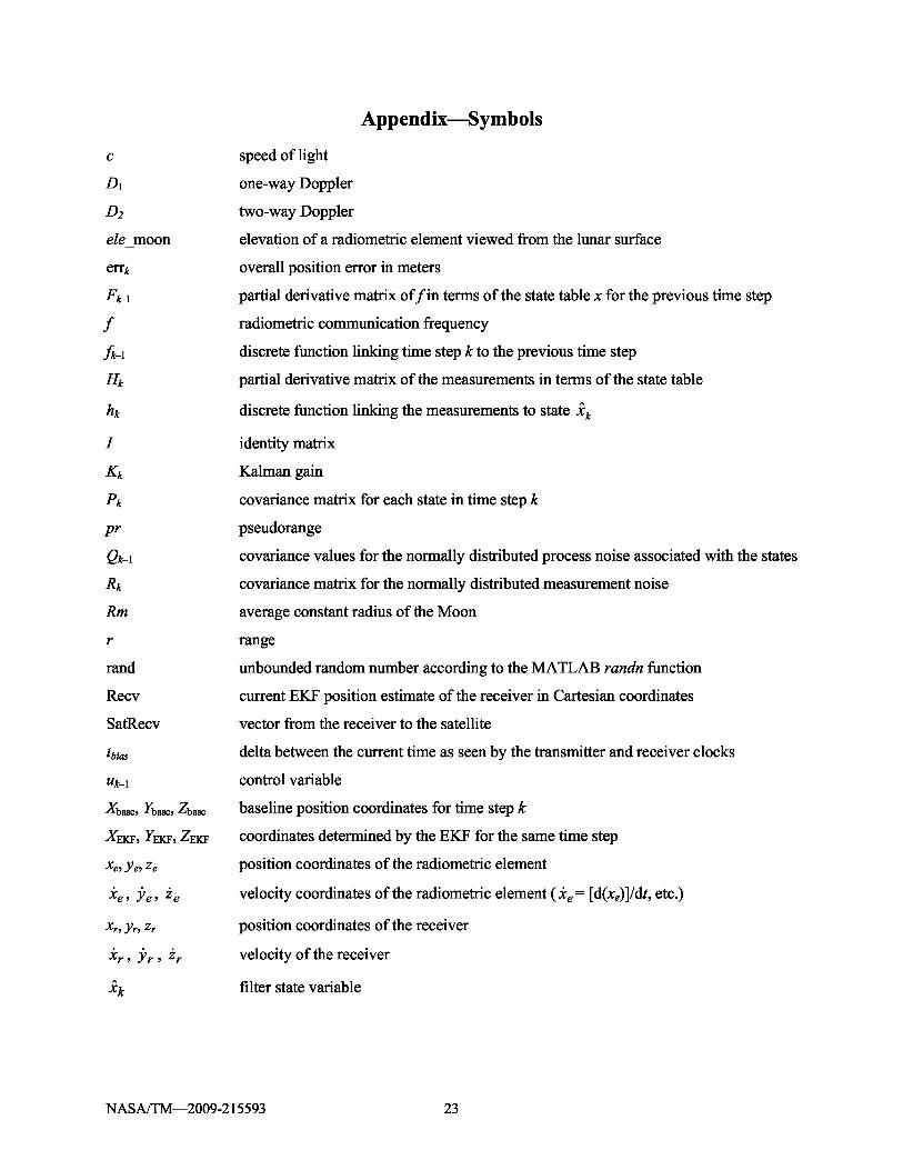
Figures 19 to 22 show the effect of reducing the number of radiometric elements available. Sincethe lunar navigation architecture remains uncertain, these charts demonstrate the type of accuracypossible given fewer elements than expected. With the assumption that LRS-1b is not present,Figure 19 shows the navigation accuracy when LRS-1a is used for two-way communication and theLCT is used for one-way communication. Figure 20 displays one-way communication for LRS-1aand the LCT. In Figures 21 and 22, no LRS is present and the LCT performs two-way and one-waycommunication, respectively.
Figure 23 presents an IMU-only configuration. In this case, no radiometric elements areconsidered in the EKF, and only the inertial data are processed.
NASA/TM—2009-215593 17

NASA/TM—2009-215593 18
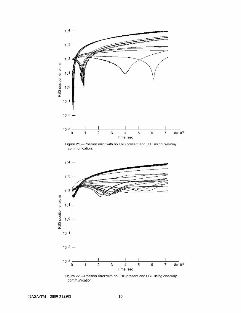
NASA/TM—2009-215593 19

Discussion
The system configuration tests in Figures 7 to 14 illustrate the importance of finding a balancebetween the number of one-way and two-way radiometric elements. The best and most consistent resultwas obtained in Figure 13, where navigational accuracy converged to less than 1 m within 5 min. In thiscase, all radiometric elements operated in two-way mode. However, the results obtained in Figures 8and 10 are similar, with the exception that the navigation path tends to be subject to greater influencefrom the random walk effect. The Figure 8 test assumed that LRS-1b was the only radiometric elementperforming two-way communication, so this setup would deliver the greatest mix of performance and energysavings. However, it is notable that the same level of accuracy is not obtainable when LRS-1a is in the samesituation (Fig. 7), so there is likely a correlation between satellite position and accuracy. Taking this intoaccount, a more consistent result is obtained when both LRSs use two-way communication (Fig. 10).
As one would expect, the initial position tests reveal that performance is somewhat dependent on theaccuracy of the starting position. When comparing Figures 15 and 16, it is not clear that initial accuracybetween 10 and 50 m has a significant performance impact. Even when the error increased 100 m, as inFigure 7, the filter output was accurate to within 3 m for the entire EVA. As the initial positionuncertainty increased to 200 and 500 m in Figures 17 and 18, accuracy decreased to approximately 20 and100 m in 5 min, respectively.
The effect of eliminating one or more radiometric elements was a pronounced decrease in the systemaccuracy. A comparison of Figures 7 and 19 shows that the system accuracy is reduced from 1 m in5 min to 10 m in 5 min when LRS-1b is eliminated. Accuracy decreases significantly by a factor of 10between Figures 19 and 20 when the remaining LRS-1a is changed to one-way communication. When noLRS was used, the EKF appeared to fail to converge, generating a position error greater than 1 km.
NASA/TM—2009-215593 20

When all radiometric elements were eliminated and the IMU was the sole source of navigation data,performance suffered drastically. The filter did not converge, yielding a position error greater than1 km over the EVA. The simulated navigation profile remained at a constant velocity, so ideally theIMU had no acceleration to report for the EVA. However, this was not the case because of drift in theacceleration bias. As the EVA duration increased, errors contributed by the IMU also increased.
Conclusions
This report presented one possible system architecture for lunar surface navigation and analyzedvarious configuration options in terms of their navigational error. It appears that the navigation systemwill yield its best performance when two-way satellite communication is available between the radio-metric receiver and the Lunar Relay Satellite. In this case, an accuracy of less than 1-m error within 5 minis attainable. The system is responsive to uncertainty in the initial starting position of the radiometricreceiver, although significant performance loss was observed only for initial errors greater than 100 m.The navigational accuracy experienced a 100 times degradation by the loss of one satellite; however, thisimpact was mitigated by a factor of 10 if the remaining satellite could perform two-way communication.The extended Kalman filter (EKF) responded poorly to the situation where a Lunar CommunicationTerminal was the only radiometric element and even worse when the IMU was used alone, withoutradiometric support.
The combination of radiometrics and inertial measurements using an EKF is viable for applications tolunar surface navigation. The presented results demonstrate the feasibility of determining a position towithin 1-m accuracy in 5 min.
Future Work
The program has some limitations that may affect its accuracy. Most notably, the use of latitude andlongitude for position data implies a constant lunar radius. The significance of this factor must be ana-lyzed further to determine the impact of exploring lunar craters or hills. One possible approach is toconvert the program to a Cartesian coordinate system, though this may reduce filter convergence.
The exploration profile discussed in this report only considers a constant velocity walk-back profile.To better understand the impact of the inertial measurement unit on the navigational system accuracy, asituation involving a changing velocity needs to be considered. Although the IMU only contributed errorin this simulation, it may prove more valuable in situations where a fine measurement granularity isneeded between radiometric data.
NASA/TM—2009-215593 21

Appendix—Symbols
c speed of light
D 1 one-way Doppler
D2 two-way Doppler
ele_moon elevation of a radiometric element viewed from the lunar surface
errkoverall position error in meters
Fk– 1 partial derivative matrix of f in terms of the state table x for the previous time step
f radiometric communication frequency
fk– 1 discrete function linking time step k to the previous time step
Hk partial derivative matrix of the measurements in terms of the state table
hk discrete function linking the measurements to state xˆk
I identity matrix
Kk Kalman gain
Pk covariance matrix for each state in time step k
pr pseudorange
Qk– 1 covariance values for the normally distributed process noise associated with the states
Rk covariance matrix for the normally distributed measurement noise
Rm average constant radius of the Moon
r range
rand unbounded random number according to the MATLAB randn function
Recv current EKF position estimate of the receiver in Cartesian coordinates
SatRecv vector from the receiver to the satellite
tbias delta between the current time as seen by the transmitter and receiver clocks
uk– 1 control variable
Xbase, Ybase, Zbase baseline position coordinates for time step k
XEKF, YEKF, ZEKF coordinates determined by the EKF for the same time step
xe, ye, ze position coordinates of the radiometric element
x& e , y& e , z& e velocity coordinates of the radiometric element ( x& e = [d(xe)]/dt, etc.)
xr, yr, zr position coordinates of the receiver
x& r , y& r, z& r velocity of the receiver
xˆ k filter state variable
NASA/TM—2009-215593 23

xˆk state table for time step k before filtering is performed
yk measurements for the current time step (e.g., range and acceleration)
(y_accelN)kmeasurement of northward acceleration
(y_accelE)k measurement of eastward acceleration
NASA/TM—2009-215593 24

References
1. Daly, P.: Navstar GPS and GLONASS: Global Satellite Navigation Systems. Electron. Commun.Engrg. J., vol. 5, issue 6, Dec. 1993, pp. 349–357.
2. Bar-Itzhack, I.Y.; and Carothers, M.L.: LRV Navigation Support at Bellcomm During the Apollo 15Mission—Case 320. Bellcomm Memorandum B71 08026, Aug. 19, 1971.http://hdl.handle.net/2060/19790072562
3. Constellation Architecture Requirements Document (CARD). CxP 70000, Rev. B, Feb. 13, 2008.http://www.everyspec.com/NASA/NASA+-+CxP+PUBS/download.php?spec=CxP_70000_CARD_RevB.005804.pdf
4. Simon, Dan: Optimal State Estimation: Kalman, H Infinity, and Nonlinear Approaches. Wiley &Sons, 2006.
5. Honghui, Qi; and Moore, J.B.: Direct Kalman Filtering Approach for GPS/INS Integration.Aerospace and Electronic Systems, IEEE Trans., vol. 38, issue 2, 2002, pp. 687–693.
6. Scherzinger, Bruno M.; and Woolven, Steven: POS/MV—Handling GPS Outages With TightlyCoupled Inertial/GPS Integration. OCEANS ’96, MTS/IEEE, Prospects for the 21st Century,Conference Proceedings, vol. 1, 1996, pp. 422–428.
7. Lipp, Wolfgang; Sagrestani, Vicenzo; and Sarrica, Rosario: Integrated GPS/Fibre Optic Gyro LandNavigation System. Position Location and Navigation Symposium, 1994, IEEE, 1994, pp. 447–452.
8. Call, Curt, et al.: Performance of Honeywell’s Inertial/GPS Hybrid (HIGH) for RNP Operations.Position, Location, and Navigation Symposium, 2006 IEEE/ION, 2006.
9. Bhasin, Kul B.; Warner, Joseph D.; and Anderson, Lynn M.: Lunar Communication Terminals forNASA Exploration Missions: Needs, Operations Concepts, and Architectures. InternationalCommunications Satellite Systems Conference, 2008.
10. David, Leonard: Lunar South Pole Landing Sites Studied. Space.Com , Imaginova Corp., 2003.http://www.space.com/missionlaunches/moon_southpole_030604.html
11. Ely, Todd: Stable Constellations of Frozen Elliptical Lunar Orbits. J. Astronautical Sci., vol. 53,no. 3, 2005, pp. 301–316.
12. Lemon, Kimber; and Welch, Bryan W.: Comparison of Nonlinear Filtering Techniques for LunarSurface Roving Navigation. NASA/TM—2008-215152, 2008. http://gltrs.grc.nasa.gov
NASA/TM—2009-215593 25

REPORT DOCUMENTATION PAGE Form ApprovedOMB No. 0704-0188
The public reporting burden for this collection of information is estimated to average 1 hour per response, including the time for reviewing instructions, searching existing data sources, gathering and maintaining thedata needed, and completing and reviewing the collection of information. Send comments regarding this burden estimate or any other aspect of this collection of information, including suggestions for reducing thisburden, to Department of Defense, Washington Headquarters Services, Directorate for Information Operations and Reports (0704-0188), 1215 Jefferson Davis Highway, Suite 1204, Arlington, VA 22202-4302.Respondents should be aware that notwithstanding any other provision of law, no person shall be subject to any penalty for failing to comply with a collection of information if it does not display a currently valid OMBcontrol number.PLEASE DO NOT RETURN YOUR FORM TO THE ABOVE ADDRESS.1. REPORT DATE (DD-MM-YYYY) 2. REPORT TYPE 3. DATES COVERED (From - To)01-06-2009 Technical Memorandum4. TITLE AND SUBTITLE 5a. CONTRACT NUMBERA Kalman Approach to Lunar Surface Navigation Using Radiometric and InertialMeasurements
5b. GRANT NUMBER
5c. PROGRAM ELEMENT NUMBER
6. AUTHOR(S) 5d. PROJECT NUMBERChelmins, David, T.; Welch, Bryan, W.; Sands, O., Scott; Nguyen, Binh, V.
5e. TASK NUMBER
5f. WORK UNIT NUMBERWBS 903184.04.03.02.02
7. PERFORMING ORGANIZATION NAME(S) AND ADDRESS(ES) 8. PERFORMING ORGANIZATIONNational Aeronautics and Space Administration REPORT NUMBER
John H. Glenn Research Center at Lewis Field E-16883Cleveland, Ohio 44135-3191
9. SPONSORING/MONITORING AGENCY NAME(S) AND ADDRESS(ES) 10. SPONSORING/MONITOR'SNational Aeronautics and Space Administration ACRONYM(S)
Washington, DC 20546-0001 NASA
11. SPONSORING/MONITORINGREPORT NUMBER
NASA/TM-2009-215593
12. DISTRIBUTION/AVAILABILITY STATEMENTUnclassified-UnlimitedSubject Category: 17Available electronically at http://gltrs.grc.nasa.govThis publication is available from the NASA Center for AeroSpace Information, 301-621-0390
13. SUPPLEMENTARY NOTES
14. ABSTRACTFuture lunar missions supporting the NASA Vision for Space Exploration will rely on a surface navigation system to determine astronautposition, guide exploration, and return safely to the lunar habitat. In this report, we investigate one potential architecture for surfacenavigation, using an extended Kalman filter to integrate radiometric and inertial measurements. We present a possible infrastructure tosupport this technique, and we examine an approach to simulating navigational accuracy based on several different system configurations.The results show that position error can be reduced to 1 m after 5 min of processing, given two satellites, one surface communicationterminal, and knowledge of the starting position to within 100 m.15. SUBJECT TERMSMoon; Navigation; Lunar surface; Surface navigation; Radio navigation; Satellite navigation; Systems; Positioning
16. SECURITY CLASSIFICATION OF: 17. LIMITATION OF 18. NUMBER 19a. NAME OF RESPONSIBLE PERSONABSTRACT OF
PAGESSTI Help Desk (email:[email protected])
a. REPORT b. ABSTRACT c. THIS 19b. TELEPHONE NUMBER (include area code)U U PAGE UU 30 301-621-0390
UStandard Form 298 (Rev. 8-98)
Prescribed by ANSI Std. Z39-18


![Visual Inertial Navigation Short Tutorialmars.cs.umn.edu › tr › Stergios_VINS_Tutorial_IROS19.pdf · Frontend: Multi-state Constraint Kalman Filter (MSCKF) [1] •State Vector](https://img.dokumen.tips/doc/110x75/5f13575e4ce0fc1cf1026121/visual-inertial-navigation-short-a-tr-a-stergiosvinstutorialiros19pdf.jpg)