Embed Size (px)
Citation preview
A Java API and Web ServiceGateway for wireless M-Bus
Bakkalaureatsarbeit
zur Erlangung des akademischen Grades
Bakk. techn.
im Rahmen des Studiums
Software & Information Engineering
eingereicht von
Ralph HochMatrikelnummer 0405156
an derFakultät für Informatik der Technischen Universität Wien
Betreuung: Ao.Univ.Prof.Dr. Wolfgang KastnerMitwirkung: Dipl.-Ing. Markus Jung
Wien, 24. Oktober 2013(Unterschrift Verfasser/in) (Unterschrift Betreuung)
Technische Universität WienA-1040 Wien � Karlsplatz 13 � Tel. +43-1-58801-0 � www.tuwien.ac.at


A Java API and Web ServiceGateway for wireless M-Bus
Bachelor Thesis
submitted in partial fulfillment of the requirements for the degree of
Bachelor of Science
in
Software & Information Engineering
by
Ralph HochRegistration Number 0405156
to the Faculty of Informaticsat the Vienna University of Technology
Advisor: Ao.Univ.Prof.Dr. Wolfgang KastnerAssistance: Dipl.-Ing. Markus Jung
Vienna, 24. Oktober 2013(Signature of Author) (Signature of Advisor)
Technische Universität WienA-1040 Wien � Karlsplatz 13 � Tel. +43-1-58801-0 � www.tuwien.ac.at

Erklärung zur Verfassung der Arbeit
Ralph HochNeulerchenfelder Strasse 87/33, 1160 Wien
Hiermit erkläre ich, dass ich diese Arbeit selbständig verfasst habe, dass ich die verwende-ten Quellen und Hilfsmittel vollständig angegeben habe und dass ich die Stellen der Arbeit -einschließlich Tabellen, Karten und Abbildungen -, die anderen Werken oder dem Internet imWortlaut oder dem Sinn nach entnommen sind, auf jeden Fall unter Angabe der Quelle als Ent-lehnung kenntlich gemacht habe.
(Ort, Datum) (Unterschrift Verfasser/in)
i


Abstract
M-Bus Systems are used to support the remote data exchange with meter units through a net-work. They provide an easy extend able and cost effective method to connect many meterdevices to one coherent network. Master applications operate as concentrated data collectorsand are used to process measured values further. As modern approaches facilitate the possibilityof a Smart Grid, M-Bus can be seen as the foundation of this technology. With the current focuson a more effective power grid, Smart Meters and Smart Grids are an important research topic.
This bachelor thesis first gives an overview of the M-Bus standard and then presents a Javalibrary and API to access M-Bus devices remotely in a standardized way through Web Services.Integration into common IT applications requires interoperable interfaces which also facilitateautomated machine-to-machine communication. The oBIX (Open Building Information Ex-change) standard provides such standardized objects and thus is used to create a Web Servicegateway for the Java API.
iii


Contents
1 Introduction 1
2 M-Bus Standard 32.1 Introduction . . . . . . . . . . . . . . . . . . . . . . . . . . . . . . . . . . . . 32.2 History . . . . . . . . . . . . . . . . . . . . . . . . . . . . . . . . . . . . . . 32.3 Purpose . . . . . . . . . . . . . . . . . . . . . . . . . . . . . . . . . . . . . . 52.4 Related Standards . . . . . . . . . . . . . . . . . . . . . . . . . . . . . . . . . 142.5 Conclusion . . . . . . . . . . . . . . . . . . . . . . . . . . . . . . . . . . . . 15
3 oBIX Standard 173.1 Introduction . . . . . . . . . . . . . . . . . . . . . . . . . . . . . . . . . . . . 173.2 oBIX functions . . . . . . . . . . . . . . . . . . . . . . . . . . . . . . . . . . 183.3 oBIX examples . . . . . . . . . . . . . . . . . . . . . . . . . . . . . . . . . . 19
4 Wireless M-Bus Java Library and API 214.1 Java Library Architecture . . . . . . . . . . . . . . . . . . . . . . . . . . . . . 224.2 Telegram structure . . . . . . . . . . . . . . . . . . . . . . . . . . . . . . . . 264.3 Java Library Usage . . . . . . . . . . . . . . . . . . . . . . . . . . . . . . . . 284.4 Integration into oBIX based IoTSyS framework . . . . . . . . . . . . . . . . . 32
5 Conclusion 37
List of Figures 38
List of Tables 38
Listings 38
Bibliography 41
v

CHAPTER 1Introduction
Current power supply systems do not allow a fast and flexible adaptation and are thereforenot able to cope with modern approaches for energy conservation. Smart meter devices are thefoundation of a newer, smarter energy grid and facilitate the power authorities to deal with on-demand, real-time power consumption values. In Austria, a legal ordinance has been publishedwere general conditions are specified. These conditions include that 70% of all domestic homeshave to be equipped with smart meters by the year 2017 and that power suppliers have a mon-itoring and reporting obligation (Intelligente Messgeräte - Einführungsverordnung (IME-VO)and Intelligente Messgeräte - Anforderungs VO (IMA-VO)) [6–8].
Data exchange between house holds (smart meter) and transaction server components (energysupplier) is realised via power line communication (PLC) using a standard on advanced meteringinfrastructure [31].
However, PLC only allows a very static data handling approach and it is difficult to applysecurity arrangements that satisfy modern technology standards. Considering that there are alsoother issues, like interference with PLC frequency bands, another approach would be desirable.
Additional modules for smart meter devices allow communication via the M-Bus wirelessstandard [20]. This enables the utilization of TCP/IP technology standards and furthermoreallows a near real-time data processing [29]. This is, especially for end consumers, a majoradvantage, because it provides the opportunity to see effects and results of electronic devicesalmost immediately. For the energy supplier, a reduction of communication complexity as wellas reusing or adapting already existing security mechanism would allow a simpler and moreefficient integration with other parts of the energy system. As a bonus it would enable the nearreal-time tracking of energy consumption data.
To achieve this task, a framework is needed that establishes secure data exchange betweensmart meter devices and high-end systems utilizing the advanced metering infrastructure.
This bachelor thesis presents a JAVA library and API that enables remote interaction withwireless M-Bus devices. Various functions, such as retrieving and storing values from data
1

endpoints or support of different telegram types, are supported by the API. In addition, encryptedas well as plain data telegrams are supported. Furthermore, a Restful Web Service has beenimplemented. It makes use of oBIX (Open Building Information Exchange) [28] to representthe wireless M-Bus meters and serves as a gateway between applications and the meter itself.
The remaining parts of this bachelor thesis are organized in the following manner. Section 2gives an overview on the current M-Bus standard and especially puts focus on how communi-cation between devices is realized. In addition, a short introduction to the lower level parts ofthe standard is given. Section 3 shows the oBIX standard and describes how communicationcan be realized following this approach. In Section 4, the final prototype and its functionality isspecified, including examples on how it can be used to interact with meter devices. Additionally,a description of how telegrams are transferred in a specific set up is given. Finally, Section 5provides a conclusion for this thesis.
2
CHAPTER 2M-Bus Standard
2.1 Introduction
M-Bus or Meter-Bus is a standardized system which was developed to support the remote,through a network, read-out of various utility meter systems. These meter systems include heat,electricity and various other units. Remote access allows an M-Bus master to access and retrievethe measured values of the meters. End devices such as laptops or tablets are then used to furtherprocess the retrieved data.
2.2 History
In the early 1990s, since there was no system available that enabled remote access of meterdevice read-outs, a new approach had to be specified. Professor Dr. Horst Ziegler of the Univer-sity of Paderborn developed an idea for a distributed metering bus system. In cooperation withcompanies such as Texas Instruments Germany GmbH and Techem GmbH a first prototype wasdeveloped. Initially, the idea was to provide a specific physical definition on how the meters canbe accessed as well as a protocol specification on how the data should be interpreted.
This effort was later standardized and became a European Standard. The standard can befound under EN 13757: Communication systems for meters and remote reading of metersand consists of several parts. The following list gives a short introduction:
• EN 13757-1: Data exchange [14]The first part of the standard describes the data exchange and communication of meters aswell as the remote read-out of meter data. It provides application specific information andgives an overview of the used communication model.
3

Figure 2.1: M-Bus Standard Setup
• EN 13757-2: Physical and Link Layer [15]In this part the physical and link layer are covered. It describes how baseband communi-cation in meter systems is realized over twisted pair media.
• EN 13757-3: Dedicated application layer [16]An application protocol on how meter read-outs have to be interpreted is defined. Thisprotocol makes meters from different vendors interoperable. The application layer utilizesthe physical and link layer described by EN 13757-2.
• EN 13757-4: Wireless meter readout (Radio meter reading for operation in the 868 MHzto 870 MHz SRD band) [13]As modern approaches often use wireless communication, a standard has been defined tosupport this approach. It defines the physical and link layer for wireless devices and refersto EN 13757-2.
• EN 13757-5: Wireless Relaying [12]This part can be seen as an extension to EN 13757-4 and describes how routed wirelessnetworks for meter read-outs can be established. As meter and bus master devices can bephysically located far apart from each other, a relaying can be necessary.
4
• EN 13757-6: Local Bus [11]This standard describes parameters of the electronic link layer of a local bus system forthe communication with meters within the bus system.
The M-Bus standard is closely related and based on the ISO-OSI reference model. Anadvantage to base this new system on an already existing, standardized open system is that itallows an incorporation with various already established network protocols. For further details,please refer to Section 2.3.
2.3 Purpose
The key goal of meter bus systems is to provide an easy extendable, stable and cost effectiveway to interconnect many devices (slaves) over a long distance with a master application like adata center. [31]
From the existing network topologies (star, ring, bus) only a bus system is suitable for thistask as it allows serial transmission of data over a common used transmission medium as wellas easy addable new devices. Meter systems are used to measure the consumption of variousresources like heat or electricity. Furthermore, they deal with end user data which is oftenused to provide billing and therefore the receiving of accurate data is indispensable. Thus,transmission integrity is very important and the bus system needs to be insusceptible againstexternal interference such as inductive interference. [21]
As there are probably many end devices used in such a bus system it is imperative to keepthe operating costs as well as the installation costs as small as possible. In calculating the costs,it is necessary to keep in mind that the transmission distance may be very long and thus thetransmission medium needs to be cost effective (e.g. standard medium, no additional shielding).Complexity of installation of new end devices should be kept simple, as it might be necessary toadd devices or facilities during bus system operation. Remote powering enables meter slaves tobe independent.
Inaccuracies in the existing standard enabled manufactures to develop slightly different me-ter device specifications and as a result incompatible units were produced. Installation of newdevices had to be approved and tested for compatibility with the existing system and devices.
During the smart-metering initiative of the European Union these inaccuracies led to the or-ganization of an Open Metering System. An Open Metering Specification (OMS) was definedwhere the standard interpretation from different manufactures had been specified to make theminteroperable. Additionally, a 128-Bit AES encryption was introduced for the powerline com-munication as well as the wireless transmission. As of 2009, OMS has been proposed to theEuropean Committee for Standardization as a supplement to the existing standard.
The ability of the M-Bus system to deal with many meter devices makes it the foundation ofmodern energy grids. The bi-directional communication method enables remote control of themeter slaves that are in place. The near-field communication of modern meters is often realizedutilizing the M-Bus system.
5
In combination with Smart Meters a near real-time transmission of power consumption datato power supply companies can be established. The term “Smart Meter” usually refers to elec-tricity meters, but can be used for other energy sources like water or gas as well. Using SmartMeter devices has multiple benefits for both the consumer and the power supply industry (powersupplier, grid company, service providers).
On consumer side, it gives more transparency on actual costs and it can provide near real-time consumption data for single household appliances like TVs or computers. This up-to-datemeasurement data supports the consumer in a more efficient usage and control of his energyuse. Furthermore, it can be used to identify high energy consumption devices and help to reducethe overall energy wastage. Another advantage is that the consumer doesn’t have to rely onstatistically calculated billing information. The always up-to-date power usage data allows anexact billing information on the actual energy consumption and thus gives the consumer moretransparency on costs.
The power supply industry shares some benefits with the consumer as they can act on theeffective power consumption of each consumer individually. Monitoring energy consumptionprovides them with a better understanding of the actual total power consumption in their region.Considering systems that monitor and compare data with statistically evaluated data, it is pos-sible to develop a remote fraud detection system and help to increase the safety of consumers.Especially useful for power suppliers is the combination of smart meters with an advanced me-tering infrastructure (AMI) as it allows two-way communication [30].
This type of communication supports the remote activation or deactivation of devices asmeters can receive commands through a network. Remote access allows a variable, adaptablethrough-put of meters to react to specific energy demands. The remote activation of meters alsomakes it more cost effective as no physical installer is necessary and electricity contracts caneasily be switched between customers.
Custom pay rates, similar to telecommunication networks, and dynamic pricing based ontime or supply constraints and introduction of new value added services are possible.
Utilizing the advanced metering infrastructure, an accumulation of energy grid participants,including power suppliers, grid companies, service providers and consumers, can build a SmartGrid. Through the behaviour and the resulting information of all involved parties an intelligentenergy grid can be developed that is able to react according to energy demands or availability.In the process, a more stable, reliable, effective and efficient energy network is formed. [18]
Protocol Overview
The M-Bus protocol stack is based on the OSI-Model (Open Systems Interconnection) of theInternational Organization of Standardization (ISO). This model standardizes a communicationsystem by using several abstraction layers where each layer adds information to the previouslayer. The OSI-Model consists out of seven layers that form a protocol stack where each layerutilizes the layer underneath it. Since M-Bus does not provide all features of an ISO-OSI com-puter network, only a subset of this protocol stack needs to be used [4]. The M-Bus protocol
6

stack, thus, only uses three layers and builds upon the standard defined by IEC EN 61334-4-1.Table 2.1 gives an overview of the stack.
Number Layer Function Standard7 Application 5 EN 13757-32 Data Link 8 EN 13757-2 or EN 13757-41 Physical 4 EN 13757-2 or EN 13757-4
Table 2.1: M-Bus Protocol Stack
An advantage of utilizing this protocol stack is that higher protocol layers are independent fromtheir low level counterparts as communication is only realized between layers of the same level.This means that the implementation of the lower level layers can be changed and the functional-ity of the system is not compromised. Applying this configuration allows for example the usageof wired (EN 13757-2) as well as wireless (EN 13757-4) communication media without anychanges to the actual application. Defining a protocol for these layers allows interchangeabilityof meters. Special gateways/bridges are in place to connect network parts with different protocolimplementations.
Communication
Communication is always established between two types of devices. In case of M-Bus this isthe master and the slave (meter device). Usually, the master (caller) calls the slave (called) toretrieve the measured data and during communication each side keeps their function, hence iscaller or called. Using this kind of denotation is analogue to the common client/server architec-ture that is commonly used in network systems. In most cases the caller can be seen as the clientthat requests a functionality from the server (called). However, it does not necessarily need to bethis way. The bi-directional communication enables the meter device (server) to call the masterbus (client). In case of a malfunction, an error or an alert the meter can therefore inform themaster on this unexpected behaviour.
As communication can last over a longer period of time the partition into transactions isreasonable. Each transaction can be viewed as a request from the caller to the called. Duringtransactions caller and called alternately receive and transmit data. The following example willdemonstrate this behaviour schematically:
• Client (caller) sends (transmits) a request command to the server (called)
• Server listens for incoming commands and receives them as soon as something is trans-mitted
• Server responds (transmits) the result of the executed command
• Client listens for response (receive)
7

Physical Layer
The physical layer specifies the lowest protocol level and deals with how data is actually trans-mitted over the transfer medium. It is possible to have different kind of transports at this leveland thus it is necessary to define how bits are represented and interpreted by the communicationparticipants. The preferred method that is proposed by the EN 13757-2 standard [15] is base-band communication over twisted pair (M-Bus). Figure 2.2 shows the physical layer definitionof [15].
Figure 2.2: Physical Layer - Bit representation
As shown in Figure 2.2, transfer of bits is accomplished by voltage level changes on the masterside. Transferring a logical 1 from the master to the slave is realized by using a nominal voltagelevel of +36 volts, a logical 0 is represented by +24 volts. Slaves or meters are powered remotelyand take the required current from the bus system. The defined protocol allows a two-waycommunication, however, at the same time transmission is only possible in one direction. Ifthe slave initiates a transfer it is accomplished by modulating the consumption (current) of theslave device. Current up to 1.5 mA represent a logical “1” (Mark) in this case and a logical “0”(Space) is represented by an additional current consumption of 11-20 mA. For a full in depthdescription of the bit representation and transportation in the physical layer, please refer to [9]and [15, p. 8].
8

The implementation of the physical layer can change and therefore it is possible to exchangethe underlying transfer medium with another medium. As the data link layer is closely relatedto the physical layer, both of them are described in the same standard.
As a matter of principle, it is possible to use a different implementation of the layers definedin [15]. For further details please refer to alternatives discussed in EN 13757-1 [14].
Data Link Layer
Communication is realized by using several transactions. As mentioned before transfer is onlypossible into one direction at a time, thus a method to synchronize communication is essential.Furthermore, as an M-Bus system can contain several slaves, it is necessary to somehow identify(address) the participating meters.
This layer specifies a controlled connection between a master and a slave and is closelyrelated to the physical layer. Transmission of data is carried out by serial, asynchronous bittransfer. Synchronization can be achieved by defining how characters are transferred. Charactersare transmitted one at a time and always consist out of eleven bits. Each character begins witha start bit (space) and is followed by eight data bits, a parity bit (check for equality) and a stopbit (mark). The start and stop bits mark the beginning and the end of a character and supportsynchronization. [15]
To send meaningful data, characters are organized in defined telegrams which are shown inTable 2.2.
Single Character Short Frame Control Frame Long FrameE5h Start 10h Start 68h Start 68h
C Field L Field = 3 L FieldA Field L Field = 3 L FieldCheck Sum Start 68h Start 68 hStop 16h C Field C Field
A Field A FieldCI Field CI FieldCheck Sum User Data (0-252 Byte)Stop 16h Check Sum
Stop 16h
Table 2.2: Data Link Layer - telegram formats M-Bus
Each row of Table 2.2 represents one byte (plus the bits for start, parity and stop). Some ofthese bytes can have special meanings and are used to control transfer or address participants:
• C (Control) Fieldsupports determination of communication direction. Additionally, it encodes the function
9

of the telegram. For a complete list of functions please refer to [4] as this field is quitecomprehensive. An example for a control value is:SNDNKE: 40h short frame - initializes slave
• A Field (primary address)has the purpose to identify (address) the communication endpoint and is used by both thesender and the receiver. As this field is only one byte long it is theoretical possible toaddress 256 communication participants at max. However some addresses have a specialpurpose and can’t be used for devices [16, p. 67]. This limits the directly addressabledevices to 250.
• CI Field (Control Information Field)is from high importance for the application layer and is used to distinguish between longand short frame telegrams.
• L (Length) Fielddefines number of bytes of the meter data (including C, A and CI Fields).
• Check Sumchecks if the transmission has been correct. It is configured by specific parts of each tele-gram and serves as an additional protection for synchronization or transmission failures.The standard defines CRC (cyclic redundancy check) as the used method.
In addition, a short explanation of the different telegram formats is given:
• Single Charactera single chracter is used to acknowledge that the telegram has been received (ACK: E5h).
• Short Framea short frame has a fixed size of five bytes and has a specific format. The function iscontrolled via the C field and participant is resolved by the A field. For example, it is usedby the master to initialize transmission of measured values from a participating meter.
• Control Frameconforms to long frames. However, no user data is transferred.
• Long Framecompared to the short frame a long frame can also contain user data of variable length.Control and address fields are used synonymously as in the short frame and also a checksum is calculated based on the contained fields.
Application Layer
The application layer serves as the final tier for the user. Custom applications need to un-derstand the protocol at this level to be able to extract meaningful data from consumer utilitymeters.
10

Usually applications work similar to client/server applications where the master device, thiscould for example be a computer, tablet or laptop, acts as a client and the utility meter acts asa server. This means that applications send requests to the server and then await the response.Although it is possible to have communication initialized by the utility meter, the other wayaround is the standard communication pattern.
As mentioned in Section 2.3 telegrams consist out of several fields - depending on the tele-gram. For this layer, the CI-Field is particular interesting as it encodes the type and sequence ofthe data that is transferred in the telegram. There are two modes in operation and depending onhow the mode bit is set, the data gets interpreted (if the mode bit is set the most significant bytegets transferred first, otherwise the least significant bit is transferred first).
Additionally the CI-Field defines what is currently transmitted. As all telegrams in the appli-cation (and higher level) layers are based upon variable user data the length has to be specifiedin the frame of the transmission (data link) layer. Data is transferred as a telegram inside theframe from the lower protocol level and consists out of a telegram header and the actual data.The telegram header can be set in different formats depending on the purpose of the transmis-sion [16]. Depending on the header several control values can be set and used to address differentkinds of operations. For example, it is possible to specify secondary addresses to identify theslave entity (in this case the meter device) or mark a synchronization package. As only 250devices are directly accessible, the secondary address allows to expand the address space. Incase a secondary address is used, the device with this “unkown” primary address gets bound tothe primary address 250 which is specifically for this purpose. This allows basically to addressan arbitrary amount of devices [16, p. 47]. Furthermore, single fields can set the encryptionmethod (signature field) of the telegram or report an alarm notification. Part of the header is alsoan identification, manufacturer and other numbers for additional information. For a complete listof possible operations see the official specification [16]. Another important task of the header isto denote if the telegram is a request or response.
Lately, there has been a lot of effort to move M-Bus systems towards a wireless based com-munication topology. As the current official norm only has rudimentary support of wirelesscommunication systems a new draft of the norm had to be formulated. As of 2012, this draftis currently under review and waiting for approval. Several changes in the specification layerhave been introduced and some of them are targeting specifically the Wireless-M-Bus systems.A specific header configuration is necessary for wireless communication and this header mustcontain at least:
• status byte
• configuration word
• access number
Other changes include (among others):
• additional encryption formats
• telegram headers for wireless communication systems
11
• more data points for electrical measurement units
Applications for end users (consumers) should build upon this level and provide a simpleinterface to query data and display it accordingly. This layer is the final layer of the protocolstack but it has to be kept in mind that only the protocol is defined and applications for endconsumers have to implement this protocol.
As the application layer protocol is quite complex there is not enough space to discuss ithere. For a complete evaluation please refer to [16] and [4].
Wireless M-Bus
Using the OSI-Model as an reference model has the advantage that implementations of layerscan be changed and the overall system still is operational. This allows new technologies to beput into place to replace existing ones. Furthermore, it is possible to interconnect different kindsof implementations by providing a bridge for each network part so that communication can beestablished throughout the network.
Modern approaches often rely on wireless connection of devices as it is very cost effective.The same applies also for M-Bus systems and thus a specification for a Wireless-M-Bus systemhas been formed and its result has been accepted as an European norm. The norm specifies howthe physical and data link layer for wireless communications operate and is specifically targetingshort range devices in unused frequency bands [13].
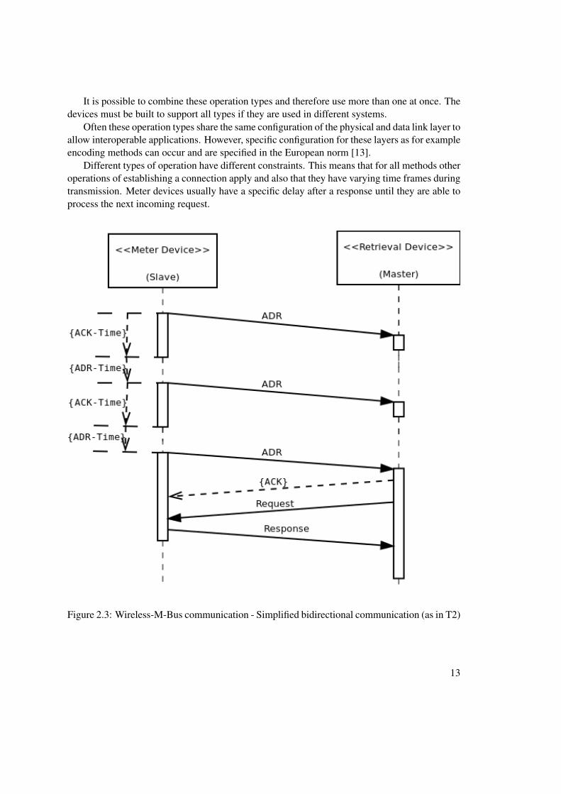
Wireless-M-Bus systems allow communication between measurement entities and non sta-tionary units (for example, master devices such as a laptop as a data collector). To achievethe communication, several operation types are specified (all operation types are identified by aname and a number):
• stationary operation method (S):This method is used for the unidirectional or bidirectional data transmission between mea-surement units and flexible master devices. Sub-methods of this type include optimizedmethods for long message headers (S1) and mobile devices (S1-m).
• frequent send operation method (T):Here small telegrams are used to transfer data in very short time frames (seconds). Thisallows to track measurement data in a very short time and is utilized by mobile devicesthat are not constantly in range of the meter itself. Furthermore, this method allows tocreate a measurement graph on almost real-time data.Sub-methods include operations for only sending data in periodic time frames or at ran-dom (T1) and a bidirectional method that uses a short initialization telegram to create atransmission channel (T2).
• time frequent receive operation method (R):A measurement unit listens for incoming messages (in a frequent interval). If it receivesone it issues a transmission channel with the sender. This method allows the master deviceto query several meter units at the same time as all of them use a separate frequencychannel.
12
It is possible to combine these operation types and therefore use more than one at once. Thedevices must be built to support all types if they are used in different systems.
Often these operation types share the same configuration of the physical and data link layer toallow interoperable applications. However, specific configuration for these layers as for exampleencoding methods can occur and are specified in the European norm [13].
Different types of operation have different constraints. This means that for all methods otheroperations of establishing a connection apply and also that they have varying time frames duringtransmission. Meter devices usually have a specific delay after a response until they are able toprocess the next incoming request.
Figure 2.3: Wireless-M-Bus communication - Simplified bidirectional communication (as in T2)
13

Figure 2.3 shows an example for a data exchange between a master and a slave unit. The com-munication mode used is a bidirectional method that is based on a short initialization frame(ADR - Access Demand Request) that is sent in periodical intervals (T2). This frame is sentout by the meter (slave) to be detectable for retrieval devices (master). After the slave devicesends such an ADR it waits for a specific time frame to receive an acknowledgement packet(ACK-Time). If such an acknowledgement is received a bidirectional communication channelis opened, otherwise the slave issues a time-out until the next ADR is sent. In case an acknowl-edgement packet is received at a master device the slave is ready to receive requests from theuser side (master). After receiving a request the slave answers with the corresponding responseand continues with its normal operation. This example simplifies the process as there are sev-eral additional constraints that apply for the communication like considering response time ortime-outs for not receiving requests after an acknowledgement [32] [13].
The current standard only covers the basic operation methods described above and is not suf-ficient for modern purposes any more. Thus, a new standard has been described and is currentlyunder review and will replace the existing European norm.
The new norm introduces several additional operation types that allow new implementationfields (meter devices which operate mainly as receivers of commands for example). Further-more, a more detailed definition of how the physical layer operates is given. Additionally, thedata link layer, and especially how the frames including their control headers are built, is de-scribed in more detail.
2.4 Related Standards
The protocol specification described in DIN EN 13757 is not the only approach to standardizeinteraction between meter and master devices. Another approach is laid down in IEC 62056where several standards for Electricity metering – Data exchange for meter reading, tariff andload control are combined. The IEC 62056 standard is the international standard version of theopen DLMS/COSEM (Device Language Message Specification/Companion Specification forEnergy Metering) specification and is issued by IEC (International Electrotechnical Commis-sion). It is maintained by the DLMS User Association and is split into several specificationswhich are published as books. The COSEM provides specifications for the Transport and Appli-cation Layer based upon the DLMS protocol [5]. This standard is also available as an EuropeanStandard under DIN EN 62056-21 [22].
SML (Smart Message Language) provides a communication protocol for meter devices andallows data exchange in between them and retrieval devices [33]. Several meter devices supportthis communication protocol such as SyM2 (synchronous actual usage meter), eHZ (electricalhousehold meter) where SyM2 is based on an Ethernet connection and eHZ uses an infraredinterface according to the standard described above, DIN EN 62056-21. Communication isrealized based on small messages which are called files. All messages consist of a start and endsequence. The messages themselves have data stored (e.g. data values or commands). Messagescan be sent in a standard text format or in a compressed binary format [25] [24].
A comparison between DLMS/COSEM and SML can be found in [17].
14

In the North American market often a standard published by the American National StandardsInstitute (ANSI) is used. ANSI C12.18 describes a communication protocol that is used in a two-way communication with meter devices. This particular standard describes the lower protocollevels and how communication via an ANSI Type 2 Optical Port can be realized. Subsequently,other standards or extensions have been published which extend the original standard by othertechnologies like for example modems (ANSI C12.21) which are better suited for automaticmeter reading. The ANSI C12.22 standard describes a protocol for transporting data specified inANSI C12.19 (table data) over networks. The purpose is to enable interoperability in betweenmaster and meter devices. ANSI C12.22 also supports data transport via TCP or UDP. Fordetailed information please refer to [2, 3].
2.5 Conclusion
Modern approaches that enable a more economic use of resources are a vibrant alternative tocurrently established inflexible systems. Smart Grids make a dynamic use of resources possibleas they allow to use them on an “as needed” basis. This helps to cut costs which not only theelectrical network supplier but also the customers benefit from. A more transparent view on theactual usage of energy provides the customers with the possibility to have more control overtheir energy consumption and to reduce or eliminate unnecessary units from their daily use.
This is a big advantage and makes home automation possible. Single devices can be ad-dressed individually and even controlled by the consumers themselves. To enable such an au-tomation a technology is necessary that creates the opportunity to communicate with devicesthrough a network. Manual steps, such as reading meter values, are not necessary any more.
M-Bus systems provide such an infrastructure and are an integral part of home automationand thus also a modern Smart Grid. Smart Meter devices are very flexible as they are able toreceive commands over a network and operate accordingly. Not only is it possible to receivenear real-time energy measurement data but also to control single devices. Applications canbe built for various purposes and in doing so allow consumers access to devices that they cancontrol through a simplified user interface.
The idea of such an easy extendible, flexible and cost effective infrastructure has beenformed, refined and reached the status of an European norm which now enables interoperabilitybetween different vendors. Wireless communication methods are included as well for seminalapplication scenarios with mobile devices. Refined versions of the EN 13757 norm are alreadyunder review and will expand the possible scenarios even more.
However, since this is a relatively new infrastructure, several points remain that need to beclarified. Security mechanisms have to be put into place to help to prevent fraud and ensure theconsumer security. Newer versions of the EN 13757 norm already include modern encryptionmethods that help to secure the data that is transmitted through the infrastructure. How larger-scale applications deal with other security issues related to Smart Grid technologies remains tobe seen.
Another point is that currently the infrastructure, from a hardware perspective at the con-sumer side, is not available. The next step is to bring this infrastructure to the consumer. Thiswill be an ongoing process over a longer period of time.
15

In conclusion, it may be said that the M-Bus infrastructure can be seen as the foundation ofhome metering environment and later on of a modern Smart Grid. Smart Meter devices facilitatethe possibility of a more economic energy consumption in a modern Smart Grid environment.
16

CHAPTER 3oBIX Standard
3.1 Introduction
With the development of modern Internet technologies, the term ubiquitous computing is be-coming more and more common. Consumers want to be able to access and control variousdevices, for example, a home heating system, through gadgets like mobile phones. This meansthat devices or systems must be remotely accessible through a common infrastructure that sup-port controlling these devices. All these requirements are often subsumed under the term Internetof Things [10, 19].
Only a small amount of systems provide built in remote access and if they do they oftenrely on custom and proprietary communication infrastructures. Furthermore, low level commu-nication protocols, for example, the M-Bus standard, are very common and prevent an easy touse data exchange between various devices. However, these low level communication protocols,such as the M-Bus standard, provide the foundation for and are used to build applications uponthem. Systems such as smart grids are an example for this [34].
To facilitate an easy to use communication between devices a common communication in-frastructure is necessary. Web Services are widely accepted and can be used to accomplish thistask. In addition, devices that communicate with each other need to “speak” the same language,which means that they have to communicate using a standardized protocol. The oBIX (OpenBuilding Information Exchange) standard tries to fill in this gap with a proposal for a stan-dardized communication protocol for devices. The standard is implemented as a RESTful WebService infrastructure and uses technologies like XML, HTTP and URIs [28].
Devices that participate in oBIX-based communication can be called oBIX entities and canexchange information with each other through Web Service calls. This means that also automaticmachine-to-machine communication can be accomplished which helps the task of home automa-tion in general and smart grids in particular [23]. Since communication is realized through WebService calls, interaction can be realized with various devices. As an example we can imag-ine a Web Service that allows the administration of a home heating system throughout modern
17
smartphones. New devices can be made public by registration in an oBIX based system and thenprovide additional functionality [27].
3.2 oBIX functions
The main focus of oBIX is to provide a way to communicate with devices. oBIX supportsthree different types of interaction through a REST based infrastructure: read an object, write anobject and invoke an operation. The payload transferred is an XML representation of the oBIXstandard. To identify entities or objects URIs (Uniform Resource Identifier) are used that canalso be used to mark the location of a device which means that they can also be seen as URLs(Uniform Resource Locator). For an example, please see Section 3.3.
Basically, the oBIX specification provides a small fixed set of object types which can bemapped to XML structures. An oBIX object of type obj (which serves as the root element of alloBIX objects), for example, defines several properties like name or href, to identify the object,among others. All other types are derived from this basic type.
Another key concept of oBIX are the Contracts. Contracts can be seen as a template ob-ject that other objects reference to through an is attribute. Properties that reference to such acontract can be accessed according to the contract specification and thus provide methods ac-cordingly. Furthermore contracts can be used to define new types and also allow abstractionthrough inheritance. This allows you to introduce new types which enrich base types with ad-ditional functionality. An object can reference more than one template and templates can havemultiple inheritance. This mechanism makes oBIX easy to use as well as easy extendible.
As already mentioned objects can reference each other through URIs. Beside that it is alsopossible to have nested objects. As an example, we will refer to a home heating system againwhere the heating system could be presented by an oBIX object which has several heaters ascontainment properties. These heaters are themselves oBIX objects. In this case, also all objectswould follow a contract specification.
In home automation usually certain aspects of the systems are of interest. In our homeheating example we could have several heaters and of each of them their current temperaturesetting could be from interest. These values of sensors or similar devices are often referred to asendpoints. In case of oBIX they are identified as points and are represented as a contract namedobix:Point. Each point has a specific type (bool, real. . . ), a value and a unit. An example can beseen in Section 3.3.
Besides the features mentioned above oBIX provides more complex tasks as well. For exam-ple, a concept named watches is used to provide real-time information on objects. It is possibleto register a service at a watchService and receive data updates in near real-time. Another exam-ple is the history concept which supports querying objects for values from a specific time frame.In case a query is made an XML presentation of a query is send to the service containing thetimeslot. The service then answers accordingly (please see 3.3).
Since the main focus of this thesis is not on the oBIX standard only a short overview isprovided. oBIX provides more features cannot be covered here. For further details please referto [28]
18
3.3 oBIX examples
To give a better understanding of the oBIX communication protocol a few short examples aregiven here. These examples are chosen to show certain aspects of the oBIX standard and do notintend to cover the whole communication process.
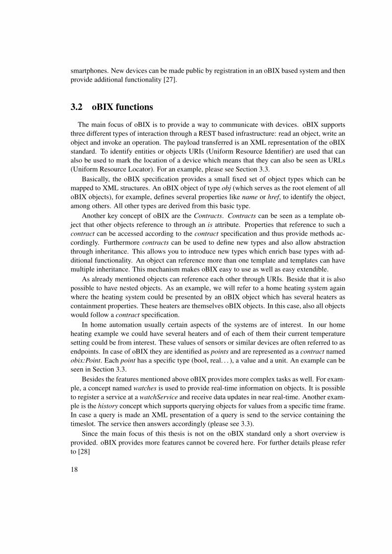
1 <obj href="/smartMeter" is="iot:SmartMeter">2 <real name="energy" href="energy" val="0.458041666666664" unit="obix:units/←↩
kilowatthours"/>3 </obj>
Listing 3.1: oBIX object SmartMeter which holds an endpoint
Listing 3.1 shows an example of a simple oBIX object. All oBIX objects can be accessedby a unique URI which means that a call of http://localhost:8080/smartMeter(assuming that the Web Service is running on localhost with port 8080) would give the resultshown in Listing 3.1. In this example it is shown how a certain object, in this case a smart meterobject, can be accessed. The object references a contract iot:SmartMeter through the is attributeand holds itself a value with the name energy which is represented as a floating point with value0.46 and the unit obix:units/kilowatthours.
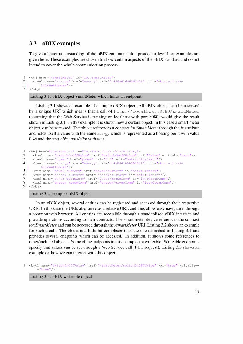
1 <obj href="/smartMeter" is="iot:SmartMeter obix:History">2 <bool name="switchOnOffValue" href="switchOnOffValue" val="false" writable="true"/>3 <real name="power" href="power" val="0.0" unit="obix:units/watt"/>4 <real name="energy" href="energy" val="0.458041666666664" unit="obix:units/←↩
kilowatthours"/>5 <ref name="power history" href="power/history" is="obix:History"/>6 <ref name="energy history" href="energy/history" is="obix:History"/>7 <ref name="power groupComm" href="power/groupComm" is="iot:GroupComm"/>8 <ref name="energy groupComm" href="energy/groupComm" is="iot:GroupComm"/>9 </obj>
Listing 3.2: complex oBIX object
In an oBIX object, several entities can be registered and accessed through their respectiveURIs. In this case the URIs also serve as a relative URL and thus allow easy navigation througha common web browser. All entities are accessible through a standardized oBIX interface andprovide operations according to their contracts. The smart meter device references the contractiot:SmartMeter and can be accessed through the /smartMeter URI. Listing 3.2 shows an examplefor such a call. The object is a little bit complexer than the one described in Listing 3.1 andprovides several endpoints which can be accessed. In addition, it shows some references toother/included objects. Some of the endpoints in this example are writeable. Writeable endpointsspecify that values can be set through a Web Service call (PUT request). Listing 3.3 shows anexample on how we can interact with this object.
1 <bool name="switchOnOffValue" href="/smartMeter/switchOnOffValue" val="true" writable←↩="true"/>
Listing 3.3: oBIX writeable object
19

After sending the code snippet shown in Listing 3.3 via a PUT request the value of switchOnOffValueis set to true.
1 <obj name="history" href="/smartMeter/energy/history">2 <int name="count" href="count" val="100"/>3 <abstime name="start" href="start" val="2013-05-22T21:43:30.298+02:00" tz="Europe/←↩
Vienna"/>4 <abstime name="end" href="end" val="2013-05-22T21:48:27.355+02:00" tz="Europe/←↩
Vienna"/>5 <op name="query" in="obix:HistoryFilter" out="obix:HistoryQueryOut"/>6 <op name="rollup" in="obix:HistoryRollupIn" out="obix:HistoryRollupOut"/>7 </obj>
Listing 3.4: oBIX history object
In Listing 3.2, it is shown that an object in oBIX can also hold a reference to a historyobject. An example for an oBIX history object can be seen in Listing 3.4. The object specifieshow many entries are currently stored in the history (count attribute, in this case 100) and fromwhich timeslot (attribute start and end). In addition, this example also shows how an oBIX objectcan provide an operation through which specific data can be requested (operation query).
oBIX objects can be quite complex and also provide mechanism for nested objects. Thisthesis only aims at giving an overview, for an exhausting description of the oBIX specificationplease see [28].
20
CHAPTER 4Wireless M-Bus Java Library and API
The main goal of the implemented prototype was to provide a higher level of abstractionand in doing so providing an API (Application Programming Interface) that is easy to use andallows interacting with a meter device. Thus, the API should provide methods to receive andwrite telegrams as well as automatically process them. The API allows applications to inter-act with wireless M-Bus meter devices and process their telegrams in an automatic way. Dataextraction functions have been put into place to provide telegram parts in a more meaningfulway. In addition, support for encryption and decryption of the communication via the AES(Advanced Encryption Standard) standard has been added. Telegram headers can be parsed andtheir payload can be processed accordingly. Using this functionality it is also possible to processtelegrams with various header formats. Since the idea was only to interact with meter devicesonly a subset of the entire M-Bus standard has been implemented.
Figure 4.1 gives a schematic overview of the API. It shows the main packages or components ofthe API and how they are related to each other. The main components are:
• Manager-ComponentThis component is used to set up and initialize the overall API. Its basic functionality is toinitialize the connector and the telegram manager itself. Although all other componentscan be used standalone, this component provides an easy way to initialize the API.
• Connector-ComponentTo establish communication with a meter device a connector is necessary. This componentestablishes a connection via a COM-Port and listens in a periodic interval for incomingmessages. The messages are then handed to the telegram manager and processed fromthere.
21
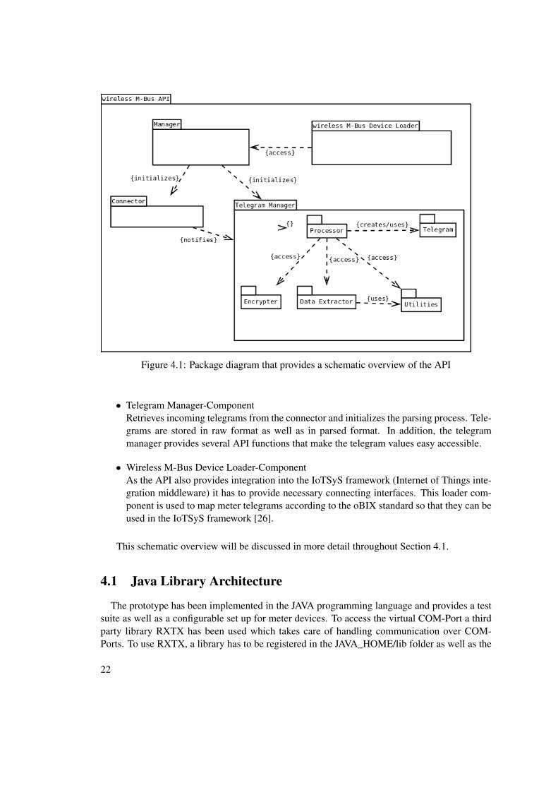
Figure 4.1: Package diagram that provides a schematic overview of the API
• Telegram Manager-ComponentRetrieves incoming telegrams from the connector and initializes the parsing process. Tele-grams are stored in raw format as well as in parsed format. In addition, the telegrammanager provides several API functions that make the telegram values easy accessible.
• Wireless M-Bus Device Loader-ComponentAs the API also provides integration into the IoTSyS framework (Internet of Things inte-gration middleware) it has to provide necessary connecting interfaces. This loader com-ponent is used to map meter telegrams according to the oBIX standard so that they can beused in the IoTSyS framework [26].
This schematic overview will be discussed in more detail throughout Section 4.1.
4.1 Java Library Architecture
The prototype has been implemented in the JAVA programming language and provides a testsuite as well as a configurable set up for meter devices. To access the virtual COM-Port a thirdparty library RXTX has been used which takes care of handling communication over COM-Ports. To use RXTX, a library has to be registered in the JAVA_HOME/lib folder as well as the
22

corresponding jar-File needs to be on the classpath. For further installation instructions, pleaserefer to [1].
1 Packages:2 at.ac.tuwien.auto.iotsys.gateway.connector.wmbus.reader3 at.ac.tuwien.auto.iotsys.gateway.connector.wmbus.telegrams4 at.ac.tuwien.auto.iotsys.gateway.connector.wmbus.telegrams.body5 at.ac.tuwien.auto.iotsys.gateway.connector.wmbus.telegrams.header6 at.ac.tuwien.auto.iotsys.gateway.connector.wmbus.telegrams.util7 at.ac.tuwien.auto.iotsys.gateway.connector.wmbus.test8 at.ac.tuwien.auto.iotsys.gateway.connector.wmbus.util
Listing 4.1: java prototype package structure
Listing 4.1 shows the overall package structure of the prototype and each package maycontain multiple classes. The package reader contains all classes necessary to receive and senddata to a smart meter device. In particular, this means that it listens on a configurable COM-Portfor incoming messages. It is realized as a thread based implementation so that messages canbe received asynchronously from the overall application. Through a specific listener interfacethe application is then notified upon the arrival of new information/telegrams. The telegramspackage consists out of several POJOs (Plain Old Java Objects) among other classes. Theseclasses represent the telegram structure as JAVA objects and provide meaningful methods foraccessing distinct parts of the telegram itself. Several of these objects are nested as a telegramconsists out of both a header and a body where the body itself consists out of several objects.Since a lot of the fields in the classes correspond to specific parts in the telegram a util packagehas been introduced which takes care of conversion or calculation operations. Additionally, it isused to construct an output that can be easily processed by consumers. Last but not least a testpackage is part of the prototype. Through this package several test cases can be tested withoutrelying on the actual connection to the meter device itself. These tests include conversion,calculation, output and telegram construction. Beside that there are also tests available withan actual meter device.
To give a more detailed view into the internal structure of the API several class diagrams areincluded in this thesis. Since the overall structure is quite complex the class diagram has beensplit into several diagrams where each diagram focuses on a particular part.
Figure 4.2 gives an overview of how telegrams are constructed in the API. Telegrams itself area quite complex construct since they can vary in length and field definitions depending on theheader and several other field (more on this can be found in Section 4.2). Telegrams consistsout of several distinct parts but in any case they have a header of a specific length (which canvariable) and a body. The body usually consists out of another header and the payload whichcontains the actual data values. Each field is represented through a class TelegramField. As thereare multiple fields with different functions the TelegramField class can be seen as a templateclass for several other, more specific, classes. The payload of the body usually is made up outof variable data records presented as TelegramVariableDataRecord.
23
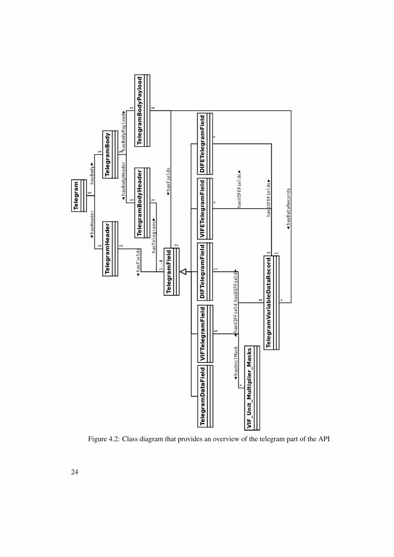
Figure 4.2: Class diagram that provides an overview of the telegram part of the API
24

In addition to the telegram structure, a manager is necessary to control and store all telegrams.This manager is used to connect to the actual meter device as well as parse telegram values. Themanager can be used to observe the connector itself and react to incoming telegrams from themeter device. Figure 4.3 gives an overview.
Figure 4.3: Telegram Manager class diagram
To instantiate a telegram manager, the interface TelegramManagerInterface has to be imple-mented. This interfaces already provides the necessary methods to process incoming telegrams.Incoming telegrams are received in the ComPortReader class and are then handed over to theclass that implements TelegramManagerInterface (in this case WMBusConnector). The interfaceenables the creation of custom telegram managers. The telegram manager is also responsible toencrypt and decrypt telegrams as well as parse them as soon as they are decrypted. Both values,raw and parsed, are stored in the telegram manager.
This concludes the overview of the API and the short introduction of its internal structure.As the API is also used and integrated into the IoTSyS framework there is also a description inSection 4.4. Please consider that not all aspects are covered in full detail here since this wouldgo beyond the scope of this paper.
25

4.2 Telegram structure
In this section, there is an example given for the telegram structure for the configuration of themeter device mentioned above. Please note that other configurations or meter devices can sendtelegrams with a different structure and although support for various telegram structures hasbeen implemented in the prototype, not all available telegrams might be interpreted erroneous.
The prototype set up was configured to send telegrams with a long header every 60 secondsas a SND_NR telegram. The structure contains first a header and then a body. The body partitself can be split into its header and its payload. The telegram structure is shown in Listing 4.2.
1 Telegram Header:2 L-Field: 1 Byte (length of telegram)3 C-Field: 1 Byte (control field)4 M-Field: 2 Byte (manufacturer field)5 A-Field: 6 Byte (address field)67 Telegram Body:8 Header:9 CI-Field: 1 Byte (control input field)
10 Acc-Field: 1 Byte (access number field)11 S-Field: 1 Byte (status field)12 Sig-Field: 2 Byte (signature field)13 Body:14 Payload: value of L-Field minus header length bytes
Listing 4.2: prototype meter device telegram structure
The fields described in Listing 4.2 encode various configuration settings in one single field-/byte (for example, the Sig-Field encodes information about the encryption as well as the typeof communication). Thus, it is necessary to have algorithms in place to extract the informationneeded and process them accordingly. There is already an overview on these fields given inSection 2 and therefore only an explanation on some fields is provided here.
Figure 4.4: An example for a wireless M-Bus telegram
Figure 4.4 shows an example for a telegram and how it is split into several parts (header, bodyheader and body payload). To give a better understanding of how such a telegram is processedthis example telegram is analysed in more detail in Listing 4.3.
26

1 Telegram Header:2 L-Field: 3E (length of the telegram 62 Byte)3 C-Field: 44 (value 44 means send with no answer)4 M-Field: 2C 4C (manufacturer converts to "SAM")5 A-Field: 74 44 00 15 1E 026 SerialNr: 74 44 00 15 (translates to 15004474)7 Version: 1E (version 30)8 Type: 02 (type 02 electricity)9
10 Telegram Body:11 Header:12 CI-Field: 7A (7A marks a 4 byte header)13 Acc-Field: 07 (current access number)14 S-Field: 00 (indicating no errors)15 Sig-Field: 30 85 (30 85 indicates an AES encrypted telegram)16 Body:17 Encryption: 87 01 (encryption verification)18 Payload: (encrypted payload)19 B1 B2 D2 97 F3 7A 9A DB 75 31 11...
Listing 4.3: prototype meter device telegram example
Since the telegram shown used in the prototype is quite long only the interesting parts areshown in Listing 4.3. Some of the fields, like for example the M-Field, require a more complexcalculation to retrieve the correct value. These calculations are omitted here and can be foundin [16]. The body payload itself is encrypted and basically consists of several blocks. Eachblock starts with a DIF field and is followed by a VIF field. Depending on the value of thesetwo fields the rest of the block is organized. There are multiple options on how such a block canbe constructed and therefore only the overall structure is shown here.
As the setup during the prototype implementation used an AES encryption the body payloadof the telegram has been encrypted. To encrypt and decrypt telegrams a 16-Byte key along witha CBC (Cipher Block Chaining) initialization vector is required. The method used for the AESencryption might differ and thus no initialization vector is necessary. However, a short exampleon how such a key is constructed is given in Listing 4.4. Please note that the telegram headeritself is not encrypted.
1 AES-Key:2 66 77 66 77 66 77 66 77 66 77 66 77 66 77 66 7734 CBC Initialisation vector:5 = M-Field + A-iFeld + 8 Byte-AccessNr6 = 2D 4C 74 44 00 15 1E 02 07 07 07 07 07 07 07 07
Listing 4.4: construction of telegram encryption key
Using the setting from Listing 4.4 the telegram can now be decoded.
1 RAW:2 3E 44 2D 4C 74 44 00 15 1E 02 7A 07 00 30 85 87 013 B1 B2 D2 97 F3 7A 9A DB 75 31 11 25 14 93 FA 8C 4A4 82 CD E1 F2 BB C9 F5 30 E9 A2 3F 1D 2B A7 5D B6 CA5 E4 4A 39 5D 4F 12 E2 12 1E 60 70 436
27

7 Decrypted:8 3E 44 2D 4C 74 44 00 15 1E 02 7A 07 00 30 85 2F 2F9 06 6D 09 87 C0 A1 01 34 04 03 2A ED 10 00 04 83 3C
10 00 00 00 00 04 2B 18 00 00 00 04 AB 3C 00 00 00 0011 2F 2F 2F 2F 2F 2F 2F 2F 2F 2F 2F 2F1213 Parsed:14 44h SAM 15004474 30 02h 7Ah Response from device,15 HL = 4, M-Bus16 4 00h 3085h 1 04h 03h 4 0 017 Instantaneous value 0 1109289 10^0 Wh Energy
Listing 4.5: Example telegram in different states
The examples given in this section only provide a basic overview on how telegrams can beprocessed. For an expletive description please see Section 2.3 or refer to [16].
4.3 Java Library Usage
To give a better understanding of the Java Library Architecture described in Section 4.1 ashort example on how the API can be accessed and used in an application is provided here.The main focus is to show how values of telegrams received by a smart meter device can beretrieved. In addition, a sample implementation for the TelegramManagerInterface is given thatdemonstrates how telegrams can be processed. The implementation of the TelegramManagercan vary depending on the application. The API provides a TelegramManager for the standarduse case of receiving and processing smart meter telegrams.
The first part of this section will focus on the TelegramManager itself and the latter part willdemonstrate how it can be used in an application. Please keep in mind that only a simple examplecan be shown here because the use cases can be quite complex and be embedded in larger scaleapplications.
1 package at.ac.tuwien.auto.iotsys.gateway.connector.wmbus;23 import java.util.List;45 import at.ac.tuwien.auto.iotsys.gateway.connector.wmbus.telegrams.Telegram;67 public interface TelegramManagerInterface {89 /**
10 * Processes the passed telegram and adds it to its internal storage11 * @param telegramString String representation of the telegram to be added12 */13 public abstract void addTelegram(String telegramString);1415 /**16 * Processes the passed telegram and adds it to its internal storage17 * @param telegram The telegram to be added18 */19 public abstract void addTelegram(Telegram telegram);2021 /**
28

22 * Registers the serialNr of the smart meter and the AES key that is used23 * to encrypt telegrams24 * @param serialNr The serialNr of the smart meter25 * @param aesKey The AES Key used for the encryption26 */27 public void registerAESKey(String serialNr, String aesKey);2829 /**30 * Returns a list of telegrams currently stored31 * @return the list of telegrams32 */33 public List<Telegram> getTelegrams();3435 }
Listing 4.6: the interface that telegram manager need to implement
Listing 4.6 shows the interface that each TelegramManager has to implement. The imple-mentation can be different depending on the use case and the API provides only a referenceimplementation. The following listings will only focus on the more interesting parts of theTelegramManager and demonstrate how such a TelegramManager could operate.
1 /**2 * Processes the passed telegram and adds it to its internal storage3 * @param telegramString String representation of the telegram to be added4 */5 @Override6 public void addTelegram(String telegramString) {7 Telegram telegram = this.createTelegram(telegramString);8 if(telegram != null) {9 this.telegrams.add(telegram);
10 }11 }1213 /**14 * Based on the passed string a telegram is created (if possible). The telegram15 * is, if necessary, decrypted and parsed. The final telegram is then returned16 * @param telegramString String representation of the telegram to be parsed17 * @return the created telegram18 */19 private Telegram createTelegram(String telegramString) {20 Telegram telegram = new Telegram();21 telegram.createTelegram(telegramString, false);22 if(telegram.decryptTelegram(aesKey) == false) {23 log.severe("Decryption of AES telegram not possible.");24 return null;25 }26 telegram.parse();2728 return telegram;29 }
Listing 4.7: the add method of a TelegramManager
Listing 4.7 shows the methods that are of interest to process a telegram. It is assumed that theTelegramManager has an internal storage for incoming telegrams represented as a java.util.List.
29

Furthermore, it is assumed that the necessary set up (including the key to decrypt telegrams) hasbeen provided.
The first method overrides the corresponding method from the TelegramManagerInterfaceand simply calls an internal method that is used to construct a telegram from the passed string.The resulting telegram is then, if not null, added to the internal storage, in this case a java.util.Listvariable, and then the method returns. The second method constructs the telegram itself from astring that represents a telegram. In this case, the construction is rather simple as it is assumedthat the variable telegramString provides a valid representation of the telegram. In addition,the telegram is then decrypted and parsed right away. The decryption and parsing methods areprovided by the Telegram class of the API and is automatically only performed if necessary. Theresulting telegram is then returned to the caller. Please keep in mind that this just provides asimple example on how such a telegram can be processed. In other use cases, more elaboratechecks or steps may be necessary.
Now that the functionality of the TelegramManager has been established, an overview on howto use the API and in particular this TelegramManager can be provided. For a better understand-ing, first a step by step description is given and in conclusion the full listing is shown. The goalis to receive smart meter telegrams and extract power and energy values out of them.
1 // first the telegram manager is initialized2 // and the corresponding serial number and AES key (if necessary) is set3 TelegramManagerInterface tManager = new TelegramManager();4 tManager.registerAESKey(SmartMeterStarter.SERIAL_NR, SmartMeterStarter.AES_KEY);
Listing 4.8: initializing the TelegramManager
The first step is to initialize the TelegramManager and use the correct serial numbers andAES key for its set up. Listing 4.8 shows how such a set up is accomplished.
1 // find the COM-Port under which the wireless M-Bus USB stick can be accessed2 CommPortIdentifier portId = ComPortReader.lookupPorts("/dev/ttyUSB0");3 // and initialize the connector with these values4 ComPortReader reader = new ComPortReader(portId, tManager);
Listing 4.9: initializing the ComPortReader
The second step is to initialize the connector ComPortReader. The ComPortReader is usedto establish a connection through a COM-Port (in this set up a wireless M-Bus USB stick hasbeen used). First, the correct port is identified by providing a device URI and a lookup andafterwards the ComPortReader itself can be initialized. While initializing the ComPortReaderreceives a reference to the previously generated TelegramManagerInterface stored in the vari-able tManager. This is necessary so that the ComPortReader can notify the TelegramManager-Interface via its addTelegram method. As soon as the ComPortReader is initialized it listens toincoming telegrams and, if it receives one, passes it to the TelegramManagerInterface.
After the ComPortReader has been initialized the set up is done and the API is already re-ceiving incoming telegrams and parsing them. Everything that is now missing is to extract some
30

values of the incoming telegrams. Since this is a simplified example it is assumed that, afterinitialization, the TelegramManager immediately receives some telegrams. Usually, the applica-tion logic would be placed between the initialization and the data extraction, or even more oftenthe TelegramManager itself would be used directly in the application logic.
1 // retrieve a list of currently stored telegrams2 List<Telegram> telegrams = tManager.getTelegrams();34 if(telegrams != null) {5 for(Telegram telegram : telegrams) {6 System.out.println("Energy Value: " + telegram.getEnergyValue());7 System.out.println("Power Value: " + telegram.getPowerValue());8 }9 }
Listing 4.10: retreiving telegrams from the TelegramManager
Listing 4.10 shows how data can be extracted from telegrams. First, a list of telegrams is re-ceived from the TelegramManager via the getTelegrams method. Afterwards, each telegram getsprocessed in a loop and the values are easily extracted by the getEnergyValue and getPowerValuemethods of the API.
1 // finally close the port which is connected to the smart meter2 reader.closePort();
Listing 4.11: closing the connection of the ComPortReader
To close the connection to the smart meter, the open connection in the ComPortReader hassimply to be closed. Listing 4.11 shows how this is accomplished.
The code fragments from the previous listings can be combined to form a simple applicationand is showing as a full code segment in Listing 4.12.
1 package at.ac.tuwien.auto.iotsys.gateway.connector.wmbus;23 import gnu.io.CommPortIdentifier;45 import java.util.List;67 import at.ac.tuwien.auto.iotsys.gateway.connector.wmbus.reader.ComPortReader;8 import at.ac.tuwien.auto.iotsys.gateway.connector.wmbus.telegrams.Telegram;9
10 public class SmartMeterStarter {11 /**12 * serial number of the smart meter13 */14 private static String SERIAL_NR = "15004474";1516 /**17 * the AES key that is used to encrypt meter telegrams18 */19 private static String AES_KEY = "66 77 66 77 66 77 66 77 66 77 66 77 66 77 66 77";20
31
21 public static void main(String[] args) {22 // first the telegram manager is initialized23 // and the corresponding serial number and AES key (if necessary) is set24 TelegramManagerInterface tManager = new TelegramManager();25 tManager.registerAESKey(SmartMeterStarter.SERIAL_NR, SmartMeterStarter.AES_KEY)←↩
;2627 // find the COM-Port under which the wireless M-Bus USB stick can be accessed28 CommPortIdentifier portId = ComPortReader.lookupPorts("/dev/ttyUSB0");29 // and initialize the connector with these values30 ComPortReader reader = new ComPortReader(portId, tManager);3132 // retrieve a list of currently stored telegrams33 List<Telegram> telegrams = tManager.getTelegrams();3435 if(telegrams != null) {36 for(Telegram telegram : telegrams) {37 System.out.println("Energy Value: " + telegram.getEnergyValue());38 System.out.println("Power Value: " + telegram.getPowerValue());39 }40 }4142 // finally close the port which is connected to the smart meter43 reader.closePort();44 }4546 }
Listing 4.12: full code example for a smart meter reader class
4.4 Integration into oBIX based IoTSyS framework
In addition to the standalone prototype described in Section 4.1, a plugin for a the IoTSySframework has been developed. IoTSyS aims at providing an integration middleware for theInternet of Things and allows interoperability between different devices. IoTSyS makes use ofOSGi (Open Services Gateway initiative) and thus an approach for modularization via standardAPIs has been implemented. This means that single connectors can be bundled and integratedinto the framework without changes on the actual source code. The communication stack in-cludes embedded devices based on IPv6, Web Services and the oBIX standard to enable simpleand efficient information exchange in a smart grid environment [26].
The basic idea was to include the prototype implementation for the smart meter reader as a plugininto the existing framework. To accomplish this task, a couple of new classes has been intro-duced to the prototype. IoTSyS provides a web server that allows to access registered entitiesthroughout a common interface - oBIX. Figure 4.5 gives an overview on how the communicationflow is realized.
The interaction with the IoTSyS framework is already built into the Java library and connec-tors and device loaders have been put into place. Figure 4.6 shows a class diagram for this mat-ter. Please note that the wMBusConnector class is only an abstract class which stands for a morecomplex build up described in Section 4.1. The SmartMeter interface provides the mapping for
32

Figure 4.5: Schematic overview of oBIX framework with wMBus plugin
oBIX objects and is specified according to the defined contract. The WMBusBundleActivatoris used as an entry point from the IotSyS framework and activates the device implementationthrough which the actual WMBusConnector is then initialized. The WMBusWatchDog interfaceallows to register a watch dog which is used to notify about new incoming data values.
Figure 4.6: Class diagram of WMBusConnector and IoTSyS framework
33
Since all registered entities operate according to the oBIX standard interoperability is achieved.A list of registered devices can be accessed by calling the start URL of the web server (in thiscase http://localhost:8080). To discuss the integration of the API into the IoTSySframework it is necessary to revisit Listing 3.4 from Section 3.3 (for convenience the listing is,slightly simplified, included here as well and can be seen in Listing 4.13).
1 <obj name="history" href="/smartMeter/energy/history">2 <int name="count" href="count" val="50"/>3 <abstime name="start" href="start" val="2013-05-22T21:43:30.298+02:00" tz="Europe/←↩
Vienna"/>4 <abstime name="end" href="end" val="2013-05-22T21:48:27.355+02:00" tz="Europe/←↩
Vienna"/>5 <op name="query" in="obix:HistoryFilter" out="obix:HistoryQueryOut"/>6 </obj>
Listing 4.13: Simplified oBIX history object
The operation specified in the history contract can be invoked via a POST request.
1 <obj name="query" is="obix:HistoryFilter">2 <int name="limit" val="5" />3 <abstime name="start" null="true" />4 <abstime name="end" null="true" />5 </obj>
Listing 4.14: query for an oBIX history object
To invoke such an operation, a POST request is necessary. The content of this requestis another oBIX object with a specific contract (for the query operation we have to use theobix:HistoryFilter contract). The history object is queried via the URL http://localhost:8080/smartMeter/energy/history. Listing 4.14 shows the content of such a queryPOST request. The attribute name specifies which operation is to be invoked and the followingpossible values (limit, start and end) are specified in the contract used (obix:HistoryFilter). Inthis case, there is no time constraint given but the number of results is limited to five.
1 <obj is="obix:HistoryQueryOut">2 <int name="count" href="count" val="5"/>3 <abstime name="start" href="start" val="2013-05-22T22:08:15.602+02:00" tz="Europe/←↩
Vienna"/>4 <abstime name="end" href="end" val="2013-05-22T22:08:27.605+02:00" tz="Europe/←↩
Vienna"/>5 <list of="obix:HistoryRecord">6 <obj>7 <abstime val="2013-05-22T22:08:15.602+02:00" tz="Europe/Vienna"/>8 <real val="1.0380416666666723"/>9 </obj>
10 <obj>11 <abstime val="2013-05-22T22:08:18.603+02:00" tz="Europe/Vienna"/>12 <real val="1.0388750000000055"/>13 </obj>14 <obj>15 <abstime val="2013-05-22T22:08:21.603+02:00" tz="Europe/Vienna"/>16 <real val="1.0397083333333388"/>
34
17 </obj>18 <obj>19 <abstime val="2013-05-22T22:08:24.604+02:00" tz="Europe/Vienna"/>20 <real val="1.040541666666672"/>21 </obj>22 <obj>23 <abstime val="2013-05-22T22:08:27.605+02:00" tz="Europe/Vienna"/>24 <real val="1.0413750000000053"/>25 </obj>26 </list>27 </obj>
Listing 4.15: result for a queried oBIX history object
Listing 4.15 shows the result for the query in Listing 4.14. The count attribute indicates thatare only five values contained in the result set (which is according to the contract obix:HistoryQueryOut).The results themselves can be found in a contract of obix:HistoryRecord which holds multiplevalues (in this case five). This listing also shows an example for nested objects in oBIX.
In addition, it is possible to register at a watchService and get value changes in near real-time. An optional history object for the smart meter implementation is provided as well. ThiswatchService allows the monitoring of meter devices and provides a near-real time reportingfunctionality on energy consumption. Utilizing this feature it is possible to meet the legal ordi-nance issued by the Austrian Government (IMA-VO and IME-VO).
For a full list of features please refer to [26].
35

Evaluation
In the overall setup there are two parts of interest. First the actual meter device which is aSiemens AMIS Smart Meter with an additional Amber wireless M-Bus module which enablescommunication via the wireless M-Bus standard. The configuration of the meter can be seenin Listing 4.16. This device operates as slave during the interaction. Second the receiver itselfwhich is an Amber AMB8425-M wireless M-Bus USB stick which simulates a virtual COM-Port that allows a transparent access similar to normal M-Bus devices. In this setup the USBstick is used as the master and is connected to a device that is used to receive or interact with themeter itself. Basically this stick can be used on each device that provides the necessary drivers.
1 Smart Meter:2 ID: 150077743 MAN: SAM4 Type: 02 (Electricity )5 Version: 30
Listing 4.16: smart meter configuration
The meter has been configured to send its values in a periodic interval (every 60 seconds) asan SND_NR telegram.
The overall set up has been tested on a Windows 7 and a Linux installation.
36
CHAPTER 5Conclusion
Modern technologies facilitate the usage of various devices to control and administrate sys-tems remotely. Consumers wish to be able to have access to data everywhere and at any time.Ubiquitous computing is a common term and describes the need of interoperability between dif-ferent kinds of devices, often also referred to the Internet of Things. These technologies provideus with the chance to build complex and easy to use home automation systems that can be partof a smart grid infrastructure. Smart meter devices are the foundation of this infrastructure andcan be used to access and supervise devices in home automation systems. However, not all ofthe questions surrounding this task have yet been solved.
This bachelor thesis therefore presents a JAVA library for the M-Bus standard that providesan easy to use and extendible API. Building upon this prototype, higher level applications canbe built that utilize the M-Bus communication protocol without the need of all the lower levelcomplexity of it. The prototype implemented provides a configurable setup and can be usedon various platforms. In addition, it allows encrypted telegrams to be processed so that dataexchange can be realized in a secure way. The approach used has shown that such an abstract APIcan be realized and that M-Bus telegrams can be processed in near real-time. This enables theconsumer to have accurate and up-to-date information about devices connected to a smart meter.Further implementations can provide control mechanisms with a UI so that the information canbe visualized in a more graphic way.
Furthermore, the prototype has been integrated into an oBIX server where the meter valuescan be accessed through a common Web Service infrastructure. This supports the interoperabil-ity of the device through a common standardized communication protocol - the oBIX standard.oBIX proposes an XML based Web Service infrastructure and allows access to devices throughsimple Web Service calls. The IoTSyS framework makes use of the oBIX standard and suppliesstandardized OSGi bundles that can be integrated. By doing so they can be accessed through aWeb Service and communicate via the oBIX standard and thus are able to accomplish machine-to-machine interaction and moreover automatically process information in between them.
37

List of Figures
2.1 M-Bus Standard Setup . . . . . . . . . . . . . . . . . . . . . . . . . . . . . . . . 42.2 Physical Layer - Bit representation: Page 6 of [15] . . . . . . . . . . . . . . . . . 82.3 Wireless-M-Bus communication - Simplified bidirectional communication (as in T2) 13
4.1 Package diagram that provides a schematic overview of the API . . . . . . . . . . 224.2 Class diagram that provides an overview of the telegram part of the API . . . . . . 244.3 Telegram Manager class diagram . . . . . . . . . . . . . . . . . . . . . . . . . . . 254.4 An example for a wireless M-Bus telegram . . . . . . . . . . . . . . . . . . . . . 264.5 Schematic overview of oBIX framework with wMBus plugin . . . . . . . . . . . . 334.6 Class diagram of WMBusConnector and IoTSyS framework . . . . . . . . . . . . 33
List of Tables
2.1 M-Bus Protocol Stack . . . . . . . . . . . . . . . . . . . . . . . . . . . . . . . . . 72.2 Data Link Layer - telegram formats M-Bus . . . . . . . . . . . . . . . . . . . . . 9
Listings
3.1 oBIX object SmartMeter which holds an endpoint . . . . . . . . . . . . . . . . 19
38
3.2 complex oBIX object . . . . . . . . . . . . . . . . . . . . . . . . . . . . . . . 193.3 oBIX writeable object . . . . . . . . . . . . . . . . . . . . . . . . . . . . . . . 193.4 oBIX history object . . . . . . . . . . . . . . . . . . . . . . . . . . . . . . . . 204.1 java prototype package structure . . . . . . . . . . . . . . . . . . . . . . . . . 234.2 prototype meter device telegram structure . . . . . . . . . . . . . . . . . . . . 264.3 prototype meter device telegram example . . . . . . . . . . . . . . . . . . . . 274.4 construction of telegram encryption key . . . . . . . . . . . . . . . . . . . . . 274.5 Example telegram in different states . . . . . . . . . . . . . . . . . . . . . . . 274.6 the interface that telegram manager need to implement . . . . . . . . . . . . . 284.7 the add method of a TelegramManager . . . . . . . . . . . . . . . . . . . . . . 294.8 initializing the TelegramManager . . . . . . . . . . . . . . . . . . . . . . . . . 304.9 initializing the ComPortReader . . . . . . . . . . . . . . . . . . . . . . . . . . 304.10 retreiving telegrams from the TelegramManager . . . . . . . . . . . . . . . . . 314.11 closing the connection of the ComPortReader . . . . . . . . . . . . . . . . . . 314.12 full code example for a smart meter reader class . . . . . . . . . . . . . . . . . 314.13 Simplified oBIX history object . . . . . . . . . . . . . . . . . . . . . . . . . . 344.14 query for an oBIX history object . . . . . . . . . . . . . . . . . . . . . . . . . 344.15 result for a queried oBIX history object . . . . . . . . . . . . . . . . . . . . . 344.16 smart meter configuration . . . . . . . . . . . . . . . . . . . . . . . . . . . . . 36
39

Bibliography
[1] RXTX - SerialPort Interface. http://rxtx.qbang.org/wiki/index.php/Main_Page. [Online; accessed 03-March-2013].
[2] ANSI - American National Standards Institute. Protocol Specification for ANSI Type 2Optical Port C12.18, 2006.
[3] ANSI - American National Standards Institute. Protocol Specification for Interfacing toData Communication Networks C12.22, 2008.
[4] Carsten Bories. Einrichtung einer intelligenten Ausleseeinheit für Verbrauchsmesszähler.Master’s thesis, Fachbereich Physik Universität - GH Paderborn, 1995.
[5] P. Bredillet, E. Lambert, and E. Schultz. Cim, 61850, COSEM Standards Used in a ModelDriven Integration Approach to Build the Smart Grid Service Oriented Architecture. In2010 First IEEE International Conference on Smart Grid Communications (SmartGrid-Comm), pages 467–471, 2010.
[6] Bundeskanzleramt Österreich. Intelligente Messgeräte - Anforderungs VO - IMA-VO2011. http://www.ris.bka.gv.at/GeltendeFassung/Bundesnormen/20007497/IMA-VO%202011%2c%20Fassung%20vom%2012.07.2013.pdf.[Online; accessed 24-June-2013].
[7] BUNDESMINISTERIUM für WIRTSCHAFT, FAMILIE und JUGEND. AktuelleRechtsvorschriften - Österreich. http://www.bmwfj.gv.at/ministerium/rechtsvorschriften/kundgemachte_rechtsvorschriften/seiten/listeaktuellerrechtsvorschriftenab112009.aspx. [Online; accessed24-June-2013].
[8] BUNDESMINISTERIUM für WIRTSCHAFT, FAMILIE und JUGEND. In-telligente Messgeräte - Einführungsverordnung IME-VO. http://www.bmwfj.gv.at/Ministerium/Rechtsvorschriften/kundgemachte_rechtsvorschriften/Documents/Intelligente%20Messger%C3%A4te.pdf. [Online; accessed 24-June-2013].
[9] Christof Hoentzsch. The M-Bus: A Documentation Rev. 4.8. http://www.m-bus.com/mbusdoc/md4.php. [Online; accessed 24-June-2013].
41

[10] L. Coetzee and J. Eksteen. The Internet of Things - promise for the future? An introduction.In Proceedings of IST-Africa Conference 2011, pages 1–9, 2011.
[11] DIN Deutsches Institut für Normung e. V. Lokales Bussystem, DIN EN 13757-6, 2003.
[12] DIN Deutsches Institut für Normung e. V. Weitervermittlung, DIN EN 13757-5, 2003.
[13] DIN Deutsches Institut für Normung e. V. Zählerauslesung über Funk (Fernablesung vonZählern im SRD-Band), DIN EN 13757-4, 2003.
[14] DIN Deutsches Institut für Normung e. V. Kommunikationssysteme für Zähler und derenFernablesung, DIN EN 13757-1, 2005.
[15] DIN Deutsches Institut für Normung e. V. Physical und Link Layer, DIN EN 13757-2,2005.
[16] DIN Deutsches Institut für Normung e. V. Spezielle Anwendungsschicht, DIN EN 13757-3, 2005.
[17] S. Feuerhahn, M. Zillgith, C. Wittwer, and C. Wietfeld. Comparison of the communicationprotocols DLMS/COSEM, SML and IEC 61850 for smart metering applications. In SmartGrid Communications (SmartGridComm), 2011 IEEE International Conference on, pages410–415, 2011.
[18] A. Flammini, S. Rinaldi, and A. Vezzoli. The sense of time in open metering system. InSmart Measurements for Future Grids (SMFG), 2011 IEEE International Conference on,pages 22–27, 2011.
[19] Bin Guo, Daqing Zhang, and Zhu Wang. Living with Internet of Things: The Emergenceof Embedded Intelligence. In Internet of Things (iThings/CPSCom), 2011 InternationalConference on and 4th International Conference on Cyber, Physical and Social Computing,pages 297–304, 2011.
[20] Wolfgang Hascher. Wireless-M-Bus – der neue Smart-Metering-Standard? http://www.elektroniknet.de/kommunikation/technik-know-how/kommunikations-module-u-systeme/article/1530/0/Wireless-M-Bus__der_neue_Smart-Metering-Standard/,2009. [Online; accessed 10-March-2013].
[21] Horst Ziegler, Carsten Bories. M-bus: Ausdehnung des Netzes bei unterschiedlichen Bau-draten. Fachbereich Physik Universität - GH Paderborn, dec 1995.
[22] International Electrotechnical Commission. Electricity metering - Data exchange for meterreading, 2002.
[23] H. Jarvinen, A. Litvinov, and P. Vuorimaa. Integration platform for home and buildingautomation systems. In Consumer Communications and Networking Conference (CCNC),2011 IEEE, pages 292–296, 2011.
42
[24] Wang Jiahui, Liu Xiaodan, Zeng Lei, and Hou Weiyan. The design and implementationof a wireless meter reading system. In 2011 10th International Conference on ElectronicMeasurement Instruments (ICEMI), volume 1, pages 115–120, 2011.
[25] I. Kunold, M. Kuller, J. Bauer, and N. Karaoglan. A system concept of an energy informa-tion system in flats using wireless technologies and smart metering devices. In IntelligentData Acquisition and Advanced Computing Systems (IDAACS), 2011 IEEE 6th Interna-tional Conference on, volume 2, pages 812–816, 2011.
[26] Markus Jung. IoTSyS - Internet of Things integration middleware. http://code.google.com/p/iotsys. [Online; accessed 22-March-2013].
[27] M. Neugschwandtner, G. Neugschwandtner, and W. Kastner. Web Services in BuildingAutomation: Mapping KNX to oBIX. In 2007 5th IEEE International Conference onIndustrial Informatics, volume 1, pages 87–92, 2007.
[28] OASIS Open Building Information Exchange TC. OBIX Version 1.1, Working Draft 06,2010.
[29] M.M. Rahman and A. Mto. Technologies required for efficient operation of a smart meternetwork. In Industrial Electronics and Applications (ICIEA), 2011 6th IEEE Conferenceon, pages 809–814, 2011.
[30] C. Selvam, K. Srinivas, G. S. Ayyappan, and M. Venkatachala Sarma. Advanced meteringinfrastructure for smart grid applications. In Recent Trends In Information Technology(ICRTIT), 2012 International Conference on, pages 145–150, 2012.
[31] Siemens AG. Smart Metering Infrastructure. http://www.energy.siemens.com/co/en/energy-topics/smart-grid/smart-consumption/smart-metering-infrastructure.htm. [Online; accessed 24-November-2011].
[32] Steinbeis Transfer Center - Embedded Design and Networking. Wireless M-Bus Docu-mentation. http://www.stzedn.de/wireless-m-bus-stack.html. [Online;accessed 24-April-2012].
[33] Hou Weiyan, Wang Jiahui, and Zhang Fangchang. A scheme for the application of smartmessage language in a wireless meter reading system. In 2011 Third International Con-ference on Measuring Technology and Mechatronics Automation (ICMTMA), volume 1,pages 254–257, 2011.
[34] Ling Zheng, Shuangbao Chen, Shuyue Xiang, and Yanxiang Hu. Research of architectureand application of Internet of Things for Smart Grid. In 2012 International Conference onComputer Science Service System (CSSS), pages 938–941, 2012.
43