Embed Size (px)
Citation preview
Chapter 8
A Home Constructed Gas Turbine Engine
Constructing any kind of gas turbine engine which resembles that which is fitted to an
aircraft or an industrial unit would be an enormous task. Gas turbine engines consist of
many component parts that are manufactured to the highest standards and closest
tolerances, also the materials that are used are expensive, difficult to obtain and awkward
to work with. The rotating components of gas turbine engines also have to be
dynamically balanced to within close limits.
It is possible to construct a gas turbine engine for the propulsion of model aircraft, these
units are simpler to build than commercial engines but still require a high level of skill
and facilities. Dynamic balancing of the rotating system is also required. Model gas
turbines require servicing of the bearing systems after only a few hours of operation. It is
however possible to construct a working gas turbine engine from an automotive turbo-
charger unit utilizing relatively modest engineering skills.
A gas turbine engine may be built from a complete automotive turbo-charger unit, in this
case the precision fabrication and balancing has already taken place, a basic gas turbine
engine may be simply created by adding a combustion chamber between the turbo-
charger compressor outlet and the exhaust turbine inlet. Automotive turbo-chargers are
robust and their heavy cast-construction helps reduce the risks associated with the high
speed rotational core. A correctly lubricated unit will have a life expectancy that is almost
indefinite when compared to a model turbo-jet engine. Turbo-based engine runs very
well, it cannot be considered a viable propulsion engine (Although many have
demonstrated moderate but viable thrust to weight ratios) or indeed a shaft drive unit. The
engine is too heavy for many propulsion applications and adding a reduction gearbox and
shaft drive would be very complicated. The turbo-charger based gas turbine does
however demonstrate all the characteristics of a running gas turbine engine and may form
the basis of a test bed or may simply provide fun and amusement.
The author’s turbo-charger based gas turbine engine first ran in a very crude form, over a
period of time, the design was improved and modified until an acceptable demonstration
unit was realized.
In addition to the turbo-charger itself the following systems are required to produce a
viable running engine-
1. Combustion System – simple home or workshop fabricated can type unit.
2. Fuel System – A simple propane gas supplied burner nozzle.
3. Lubrication – Pressurized circulating oil system driven by a pump.
4. Ignition System – A simple spark plug and coil or more complex electronic
exciter.
5. Starting System – High-pressure air impingement starting or windmill starting by
the application of a forced air blower at the compressor inlet.
6. A choice of Instrumentation may be provided depending on the intended purpose
of the engine.
Basic Turbo-charger unit
The gas turbine is built around a automotive diesel turbo-charger, the type used is a
Holset 3LD unit and was obtained scrap from a diesel truck. The turbo consists of a three
inch aluminum compressor wheel which is coupled to a radial inflow turbine wheel. The
rotor of the turbo is dynamically balanced to prevent vibration and resonances. The turbo
is of entirely conventional construction, the turbine is incased in a cast iron volute that
incorporates a nozzle. The nozzle itself differs from gas turbine practice and may almost
be considered a vane-less nozzle. It may also be considered to be two nozzles that lie side
by side along the axis of the turbine. The exhaust gas inlet to the turbine splits into two at
the connecting flange, two chambers are formed in the volute which then discharge onto
the turbine wheel around its circumference. The exhaust gases passing through the
turbine and are ducted out along the turbine axis where a connecting flange is provided to
accept an exhaust pipe.
The compressor section employs a vane-less diffuser (No stator blades), this consists of
an divergent aperture surrounding the compressor wheel circumference and a scroll type
air collector. The compressor casing forms the air scroll and also a discharge port, this
casing is made from cast aluminum.
The bearing system is placed between the compressor and turbine wheels. A plain journal
bearing is employed, it consists of an outer cast iron casing which is bored at the centre, a
phosphor bronze bush runs in the bearing bore and a steel connecting shaft for the
compressor and turbine runs in the bush. A thrust face is provided at the compressor end
of the shaft to prevent significant axial movement. The bearing is pressure lubricated by a
feed through the casing via a drilling, a cavity in the casing collects the oil once it has
passed around the bearing journal it then drains under gravity out through a pipe at the
bottom. The bearing casing forms the centre of the turbo, the exhaust volute is clamped
on to it at the turbine end, and the compressor scroll is bolted to it at the compressor end.
The clearances are such that under no oil pressure some radial movement and axial
movement of the rotor is possible. During operation the oil pressure holds the rotor in
place and a film of oil is formed on the bearing surfaces, the oil also dampens any
vibration as the rotor speed varies.

Combustion chamber
It terms of the gas turbine working cycle definition, the addition of a combustion
chamber to the turbo based engine completes it. The combustion chamber is fabricated
and then inserted between the compressor outlet and the turbine inlet.
The picture below illustrates the combustion chamber design. The outer casing is
constructed from a 3mm steel cylinder that is enclosed at each end by two plates. The
combustion chamber is oriented vertically that eases assembly. The bottom combustion
chamber end plate is bolted to the turbo exhaust volute input flange, a hole which
matches the volute inlet aperture is cut into the plate to allow the combustion products to
pass into the volute.
The cylindrical outer casing is fitted with a 2 1/4 inch air inlet pipe, a short length of
stainless tube is welded into the top of the cylinder. Two more holes are placed in the
cylinder, one provides a mounting for an igniter plug, the other allows a P2 air bleed for
instrumentation.
The combustion chamber top plate is drilled at the centre to provide access for a gas
burner ring supply tube. The tope and bottom plates are square, at the corners four
threaded bars clamp the plates together with the combustion chamber outer casing
sandwiched between them. At the bottom plate, the casing is sealed onto the plate by
using automotive exhaust paste. At the top plate, sealing is achieved by using a rubber
gasket.
Inside the combustion chamber casing a cylindrical metal liner has been placed, this acts
as a "Flame Holder" for the combustion process. The liner is made from 0.5mm steel
sheet, ideally this should be stainless steel (For corrosion and higher temperature
resistance), stainless is more difficult to drill and cut than mild steel, mild steel will
suffice if facilities to work with stainless steel are unavailable. The liner is open at the
bottom end and is placed over the turbine inlet. The top of the liner must be closed off, to
do this a domed cap is placed upon it. The cap makes use of a redundant gas cartridge,
the steel cartridge is formed in the right shape for the cold primary end of the liner. The
cap is fastened to the liner cylinder by three small M 2.5 stainless steel screws.
It was originally intended that different liners with various air distributions would be
investigated. The liner described was only the second to be used, the thermodynamic
results were found to be more than satisfactory considering the minimum of theoretical
design effort that went into its design. One orifice near the top provides a location for the
igniter plug, the plug protrudes into the combustion zone where it ignites the flammable
gas omitted by the burner ring.
The overall holes spacing (see diagram) and positions are not critical, this type of simple
engine is tolerant of differing air distribution within the combustion chamber as the
overall volume is generously dimensioned for the available air mass flow.
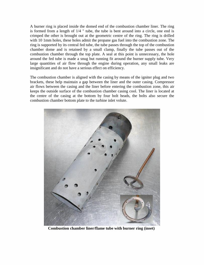
A burner ring is placed inside the domed end of the combustion chamber liner. The ring
is formed from a length of 1/4 " tube, the tube is bent around into a circle, one end is
crimped the other is brought out at the geometric centre of the ring. The ring is drilled
with 10 1mm holes, these holes admit the propane gas fuel into the combustion zone. The
ring is supported by its central fed tube, the tube passes through the top of the combustion
chamber dome and is retained by a small clamp, finally the tube passes out of the
combustion chamber through the top plate. A seal at this point is unnecessary, the hole
around the fed tube is made a snug but running fit around the burner supply tube. Very
large quantities of air flow through the engine during operation, any small leaks are
insignificant and do not have a serious effect on efficiency.
The combustion chamber is aligned with the casing by means of the igniter plug and two
brackets, these help maintain a gap between the liner and the outer casing. Compressor
air flows between the casing and the liner before entering the combustion zone, this air
keeps the outside surface of the combustion chamber casing cool. The liner is located at
the centre of the casing at the bottom by four bolt heads, the bolts also secure the
combustion chamber bottom plate to the turbine inlet volute.
Combustion chamber liner/flame tube with burner ring (inset)
Combustor liner layout
Compressor delivery tube
Air from the compressor is ducted to the combustion chamber by a tube. The compressor
outlet is connected to a 2" diameter stainless tube by means of short connecting hose. The
hose is designed to be used for turbo-charger plumbing, it is secured with two pipe clips.
The tube connects to a second right angle stainless steel tube that guides the compressor
air into the combustion chamber casing. Again the tube is secured at both ends by short
lengths of hose and pipe clips. All full speed (About 100,000 rpm) the compressor will
deliver about a 1 Bar of pressure (15 PSI), this places stress on the compressor tube and
so all fittings must be secure.
If stainless steel tube is not available for this purpose it may be possible to use a plastic
pipe to deliver air to the combustion chamber. A right angle arched bend was originally
fabricated for this purpose by gluing pipe segments together. Each segment was cut at an
angle so that a total of five pieces formed a 90 degree bend. If plastic pipe is used care
should be exercised, the pressure of the air delivery may cause it to fail, the engine may
however operate satisfactorily at low "Boost" e.g. 1/4 bar (4 PSI).
Fuel system
The fuel chosen is propane gas. Using gas greatly simplifies the design of the burner
system and also no fuel pump is required. The gas is supplied to the burner directly from
a propane gas bottle, the shut of valve on the bottle is used as the throttle control and fuel
shut off. The flow required from the bottle is very high, no regulator is used and the
bottle may require gentle heating to aid in the evaporation of the propane gas. A 3.9 Kg
capacity bottle will last for about 20 minutes, this is due to the inherent high fuel
consumption of the gas turbine.

Lubrication system
To operate satisfactorily the turbo charger requires a lubricating oil supply. When
attached to a normal reciprocating engine the turbo would have received pressurized oil
from the engine system, here, we have to reproduce a similar system.
Oil is supplied to the turbo from a modified automotive oil pump. A ford unit is used
which also incorporates an oil filter. This type originates from a ford cross flow OHV
(Overhead Valve) engine, the pump is useful as it is an externally mounted unit instead of
the more common sump mounted design. The pump body is designed to bolt onto the
engine cylinder block, the oil suction, oil delivery and the pump drive are received
through a mounting face. For the gas turbine application a connection block is fabricated
which the pump is bolted on to. The block provides galleries that duct oil to and from the
pump via hose fittings. The pump drive shaft also passes through the block where it is
fitted with an oil seal.
Belt-driven oil pump with mounting block and motor
A diagram shows how the pump mounting is constructed. The oil pump is supplied with a
drive pinion attached, the pinion should be removed by extracting a roll pin from it and
using a puller to extract the pinion gear from the shaft. The shaft will then push through
the oil seal as the pump is fitted to the body, once in place the pump shaft is fitted with a
drive pulley.
The oil pump is driven by a small electric motor. A toothed belt reduction drive reduces
the motor speed and increases the torque. The torque required to turn the pump varies
according to the temperature of the oil, when cold the pump is much harder to turn then
when hot. The pump reduction is about 5:1 yielding a speed of about 300 rpm, this
provided circulation roughly equivalent to the piston engine idle speed, lubrication of the
turbo will be adequate at this speed.
An alternative to the automotive pump is to use a purpose built motor driven oil pump or
hydraulic gear pump driven by a motor. Pressure relief valves should be fitted to maintain
moderate pressure to the turbo. Some experimentation may be required to establish the
optimum oil pressure feed setting. Values between 20-100 PSI should be satisfactory,
when cold some starting difficulties may be experienced so the ability to vary the oil
pressure and reduce it during starting will be beneficial.
An oil reservoir is placed underneath the main turbo-charger body. Oil form the reservoir
is drawn into the pump where it is filtered and pressurized, the oil then feeds the turbo
bearing assembly via a short hose. The oil returns from the turbo through a 1/2" pipe
under the force of gravity into the reservoir.
The oil reservoir is fabricated from a pre-formed aluminum box. Two holes are provided
in the lid, one for the oil drain/return the other allows for filling and inspection of the oil.
The oil temperature may be monitored by inserting a thermocouple probe into this hole.
The oil specification used for the turbo is a conventional automotive grade. Synthetic oil
is used as this type is often recommended (although not essential) for automotive turbo
charger installations. About a 2 litre quantity Mobile 1 formula is placed in the oil
reservoir. The pump was found to run fast for a few seconds until the oil was drawn into
it and then circulated into the turbo. Turbine oil should not be used for this purpose, the
turbo is designed to be lubricated with automotive oil, turbine oils are lower viscosity and
are designed for ball race type bearings and not plain bearings.

Instrumentation As with any other gas turbine engine, the two most important parameters are speed and
temperature. For experimental engine designs compressor delivery pressure (P2) is also a
useful quantity to measure.
An optical method was chosen to detect the rotation of the compressor. The rear face of
the compressor is half painted with matt black paint, the other half is polished to a mirror
finish. A small hole is drilled through the compressor casing rear face, two polymer
optical fibres are passed through the drilling and terminate close to the painted edge of
the compressor wheel. A visible red laser tube illuminates the far end of one of the fibres,
this intern illuminates the back face of the compressor. The second optical fibre picks up
reflected light from the compressor wheel and caries it to an electronic detector. As the
compressor rotates, the reflected light from it pulses on and off once every revolution,
this generates an optical signal which is processed to produce a RPM indication.
The laser ensures optimum illumination of the fibre, the fibre system was found to be
inefficient so plenty of illumination was required. Using incandescent lamps to illuminate
the fibre caused too much heat to be developed and coupled into the fibre inefficiently.
The detector consists of a photo diode unit with an integral amplifier. The detector
produces a string of pulses that are further amplified by an operational amplifier.
The detected pulses are then counted by a charge pump frequency to voltage converter
I.C. (Integrated Circuit) type LM2907. The LM 2907 will drive a 0-10V moving iron
meter that has been calibrated 0-100,000 rpm. One pulse is produced per revolution of the
compressor, when turning at 60,000 rpm the engine produces a signal of 1 KHz in
frequency.
Optical fiber receiver and amplifier

The speed sensing system is built around the back of the compressor, this allows the front
air intake area to be kept free from sensors and pickups. The uncluttered front of the
engine allows for easier coupling of the starting air blower.
When operating the engine, the signal from the tachometer system should be monitored at
different engine speeds to ensure that it is operating correctly. Failing or false indications
at speed could be dangerously misleading. It is always important with any speed
measuring system to ensue that it is calibrated and functioning correctly.
Exhaust temperature is measured using a thermocouple amplifier I.C. An AD595
amplifies the signal provided by a "K" type thermocouple, the thermocouple is placed in
the exhaust outlet of the engine. A inconel 1mm diameter "K" type probe provides a fast
response time to temperature changes and resists the high starting temperatures which are
encountered with this engine.
The AD595 is supplied from a regulated DC supply, it coverts a thermocouple signal into
a DC signal, 0-1000 degrees C produces a 0-10V signal. The exhaust gas temperature is
displayed on a standard moving coil meter.
The compressor delivery pressure P2 is displayed on a normal pressure gauge. As the
engine runs it was found that the pressure tapping was providing an unstable air supply.
The gauge pointer was found to fluctuate quickly making the reading hard to judge. A
restriction was placed in the fed pipe to the gauge, this dampens down the reading
allowing for a sensible indication of P2.
Instrumentation RPM and EGT

Ignition System
Reliable ignition of the propane gas fuel has proved to be one of the more difficult tasks
when constructing and testing the turbo based gas turbine. The igniter itself is made from
a conventional automotive spark plug. A motorcycle device is actually used, it has a
particularly long reach which is required so that it is properly inserted into the
combustion zone. A problem with many spark plugs when used in this application is that
they contain a resistor. A resistor is placed inside the plug body which helps suppress
radio interference, interference is not a major problem in this application as the igniter
will be switched off when the engine has been started. The resistor has the effect of
reducing the ferocity of the spark as it dissipates energy in the body of the plug and not at
the spark gap.
There are a number of ways of supplying sparks to the igniter plug. A electronic
switching circuit was used which operates an automotive ignition coil, this provides a
series of high voltage low energy sparks at a rate of about 50 per second. This system
worked on occasions but it was found that the combination of fuel and air required for
satisfactory ignition was quite critical.
A more reliable system made use of an aircraft igniter system, this provided a series of
high frequency sparks from a trembler coil/capacitor system. This unit provided high
voltage sparks but at higher energy than that of the automotive system. The system
produced an almost continuous arc at the spark plug gap.
The above ignition systems made use of a local 24V battery supply, if available a mains
system can be used. Neon sign transformers or industrial heating ignition transformers
may be used to provide a spark. These transformers provide a very hot continuous arc
that is ideal for ignition of the gas. The open circuit voltage of these devices may
approach 10,000 V, great care must be exercised when using them as they can provide a
lethal electric shock. Always make sure that the transformer body is earthed to the engine
metalwork and provide a warning light so that it can be seen when the ignition system is
"Live".
Warning: All ignition systems are dangerous. Exercise extreme caution when working
with high voltage ignition systems!

Starting system
One of the keys to the success of the turbo-charger based gas turbine is the provision of
an effective starting system. There are two main methods for starting this type of engine,
"air impingement starting" or "windmill starting." Air impingement starter consists of a
jet of high-pressure air that is directed onto the compressor rotating inlet guide vanes.
The impeller becomes a simple impulse turbine and is forced to rotate. A high-pressure
compressed air cylinder is required for this operation, air at up to 2000 PSI is directed
through a small nozzle which placed in the air intake region of the turbo. The system will
rotate the engine for only a limited period of time before the air supply becomes
exhausted, this may be inconvenient if the engine fails to light up quickly or is slow to
accelerate due to oil drag.
A windmill starting system may also be used with the turbo charger, this was the system
chosen and found to provide satisfactory results. A second turbo charger compressor unit
is driven by an electric motor that forms a blower, this provides a flow of air which is
coupled directly into the gas turbine air intake. The air-flow provided by the blower is
sufficient to sustain combustion and rotate the engine. The initial speed of rotation is
relatively slow (As low as 3,000 rpm) but as the combustion heats the oil, the engine
rotates faster and eventually self sustains.
The blower is coupled directly to the engine air intake, as the engine starts and becomes
self-sustaining the blower has to be removed from the air intake so that the engine can
ingest still air. The point at which the blower is pulled off has to be judged carefully and
may need some practice, too early a removal will cause the engine to stop. Late removal
is less of a problem, the blower attachment becomes restrictive to the engine air flow and
causes high exhaust temperatures.
The blower was fabricated from the compressor section of another identical Holset turbo.
A rear plate is made up which supports the motor and is bolted onto the aluminum
compressor air scroll. The motor used is a mains powered universal type that spins at
around 13,000 rpm when loaded by the blower. The blower motor is connected to a triac
operated dimmer unit so that the motor speed can be varied, the dimmer is a conventional
unit which acts as a power controller for the motor. The power control is useful, the
blower output can be varied over a wide range, the blower is turned down during engine
light up and then turned to full power for starting.
Motor driven blower unit used for starting
Starting and operating the engine
Starting a home built gas is not quite a push button affair, a number of devices require
sequenced operation and a certain amount of judgment is required. With practice an
operator can gain a feel for how the engine operates and reliable operation should be
possible. It may be advantageous to have an assistant to help with various tasks, all the
usual gas turbine safety precautions should also be adhered to.
The basic principal behind starting the engine is to light it up first at low airflows, it
should then be warmed up so that the oil becomes thinner and allows for a faster initial
rotation. Once warmed up the engine is then accelerated by increasing the fuel flow until
a point is reached where the starting air is removed and the engine self sustains. During
starting the oil supply is turned on and off to reduce the drag on the rotor, when the
engine self sustains the oil supply is turn on permanently.
To start the engine it is firstly is supplied with air from the blower, the blower is turned
down so that at this point only a breeze is present through the engine. At low settings and
with a cold engine, the air flow is insufficient to rotate the engine, but enough is present
to initiate combustion. The oil supply should also be turned on briefly and then turned off
to supply a metered amount of oil to the turbo charger bearing. The ignition should now
be switched on and the gas valve on the bottle slowly opened, a small amount of propane
is required for ignition, too much gas results in a delayed light up which may be
accompanied by a large bang. When compared to liquid fuel systems, propane seems
more difficult to light, a more precise fuel/air ratio is required. Excessive air flows may
also prevent satisfactory ignition, after a few seconds and the engine has not lit up, turn
the gas of and run the blower at full speed to purge the combustion chamber of any
residual gas.
When the gas turbine lights, a low pitched rumble will be heard coming from the
combustion chamber, the airflow and gas flow can be increased a little so that the engine
can be warmed up. A cold engine rotates only slowly due to the increased drag from the
cold oil, as the oil warms the rotor will begin to speed up. The fuel flow should be
adjusted to produce an exhaust temperature of about 300 degrees, at this point the engine
speed will be only a few thousand RPM. A period of about I minute should be allowed to
heat up the engine. During the warm up phase periodically switch on the oil supply for a
few seconds to ensure lubrication.
After it has been satisfactory warmed up the engine can be started. The air blower is
turned up to full power and the gas flow increased, at this point the RPM should begin to
rise. Gradually increase the gas flow and adjust it so that the rotor accelerates noticeably,
when wearing ear defenders the compressor whine should be heard to increase. If too
much gas is supplied, the combustion will become over rich and inefficient, flames will
appear in the exhaust and the engine may also become unnecessarily hot. The exhaust
temperature and the RPM should be watched closely, the RPM should be built up by
carefully increasing the gas flow, at about 30,000 rpm the compressor will begin to show
a significant pressure rise and the engine will self-sustain. The blower should then be
pulled off and the gas flow increased to quickly accelerate the engine to a sensible idle
speed of about 50,000 rpm. At idle speed the oil supply can be switched on and left on so
that the engine is continuously lubricated.
Failure of the engine to start may be due to a number of reasons-
If the oil is too cold the engine will not self sustain, a longer warming up period should
be allowed.
Significant gas flow is required to run the engine, if this can't be obtained, the propane
bottle should be gently heated by placing it in a bowl of warm water.
The blower described should start the engine, all the air from it should be directed
through the engine to maximize the air flow. Other blowers such as garden leaf blowers
may be suitable, small electric blowers or hair dryers are unlikely to provide enough air
for this purpose.
Once running at a steady speed the exhaust temperature should drop to about 450 degrees
C, this will depend on the efficiency of the combustion chamber, the compressor speed
and the oil temperature. At high RPMs the drag on the rotor due to the oil supply is less
significant as compared to that of the compressor load, in this case the oil temperature has
little affect.
As the engine runs the exhaust temperature, RPM and P2 may be monitored. Increasing
the propane gas fuel flow should accelerate the engine, during acceleration the exhaust
temperature will rise, degreasing the fuel flow will decelerate the engine.
During deceleration the exhaust temperature will fall until the engine settles at a slower
speed, it will then rise slightly.
The maximum permissible speed and exhaust temperature depends on the condition of
the turbo. If the unit runs very hot, the oil supply may be over heated as much heat is
dissipated by the turbine casing close to which it passes. The maximum speed and
pressure will depend on the fuel flow available; it is not advisable to operate the unit
beyond 100,000 rpm.
The engine is shut down by simply cutting the propane gas supply, it will run down very
quickly at first and then spool down at a slower rate. The oil supply should be switched
off when the speed reduces to 10,000 rpm, if left on the sealing in the turbo may not be
very effective and it will fill up with oil.
If the engine is to be restarted when hot, it will be found to be an easier operation, the hot
rotor spools up more quickly.
Conclusion The turbo-charger based gas turbine makes an ideal demonstration unit, the main
disadvantage is of course that it cannot be used to provide useful power, but it does
enable the main features of a gas turbine to be investigated. The engine may be built at
the fraction of the cost of a commercial APU, it is also cheaper and more robust than
model propulsion units.
The gas turbine could be developed further, a number of specific areas warrant
further attention-
1. The combustion chamber fabrication is crude and it is also quite large, a more compact
unit could be constructed with more efficient air distribution and better materials. Over a
period of time, the combustion chamber liner distorts due to the regular heat cycles. A
certain amount of carbon was found to build up on the burner ring, this suggested that the
air primary air distribution at this point could be improved.
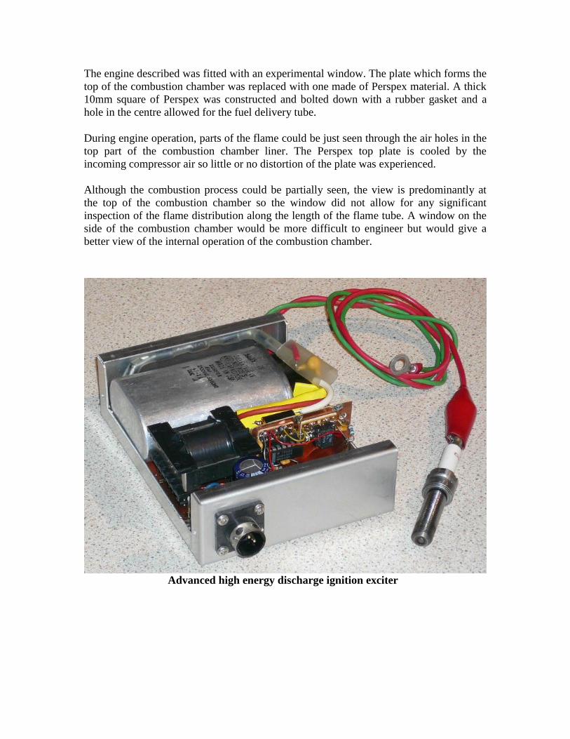
2. The ignition system could also be improved. A high-energy system was tried which
uses a special surface discharge plugs originally intended for racing IC engines. The
high-energy system yielded more reliable and predictable light up. A development to the
ignition system was the adoption of a high-energy capacitive discharge igniter system.
The combination of an electronic exciter and surface discharge plug proved to be more
effective at igniting the propane fuel. The plug used was a special automotive racing car
device that consisted of a surface gap with no protrusions. The electronic exciter
consisted of an inverter that is used to charge a 1uF capacitor up to around 2000V. The
capacitor is connected to the igniter plug and an additional trigger circuit initiates a
flashover across the plug gap. The trigger circuit provides a small high voltage spark
which breaks down the air gap and provides an ionized path which the capacitor flash
over current follows. Diodes were used to isolate the trigger voltage from the capacitor so
that they can be combined in one connection to the plug. Electronic igniter systems may
become quite complex in the areas of inverter and trigger technologies.
The position of the igniter plug within the combustion chamber could also be optimized.
3. After extended operation beyond about 10 minutes the oil temperature was found to be
high. A permanently rated engine will benefit from an oil cooler system. When cold the
oil flow could also be controlled electronically to maintain optimum lubrication without
slowing the engine.
4. The RPM measurement system makes use of an elaborate laser system and optical
fibres, this system could be replaced by a simpler magnetic pickup system or an optical
system aimed at the front of the compressor.
5. In interesting experiment is to actually view the combustion process as it occurs, it is
possible with a suitably placed window to the flames inside the combustion chamber. A
window can be placed in the outer combustion chamber casing and the positioned in such
a way so that the flame can be viewed through one or more air holes.
The engine described was fitted with an experimental window. The plate which forms the
top of the combustion chamber was replaced with one made of Perspex material. A thick
10mm square of Perspex was constructed and bolted down with a rubber gasket and a
hole in the centre allowed for the fuel delivery tube.
During engine operation, parts of the flame could be just seen through the air holes in the
top part of the combustion chamber liner. The Perspex top plate is cooled by the
incoming compressor air so little or no distortion of the plate was experienced.
Although the combustion process could be partially seen, the view is predominantly at
the top of the combustion chamber so the window did not allow for any significant
inspection of the flame distribution along the length of the flame tube. A window on the
side of the combustion chamber would be more difficult to engineer but would give a
better view of the internal operation of the combustion chamber.
Advanced high energy discharge ignition exciter