Embed Size (px)
Citation preview

A HAWAII-2RG infrared camera operated under fastreadout mode for solar polarimetryYoichiro Hanaoka ( [email protected] )
National Astronomical Observatory of Japan https://orcid.org/0000-0003-3964-1481Yukio Katsukawa
National Astronomical Observatory of JapanSatoshi Morita
National Astronomical Observatory of JapanYukiko Kamata
National Astronomical Observatory of JapanNoriyoshi Ishizuka
National Astronomical Observatory of Japan
Technical report
Keywords: solar observation, polarimetry, magnetic �eld, space weather, near-infrared, H2RG
Posted Date: November 10th, 2020
DOI: https://doi.org/10.21203/rs.3.rs-40614/v2
License: This work is licensed under a Creative Commons Attribution 4.0 International License. Read Full License
Version of Record: A version of this preprint was published on November 26th, 2020. See the publishedversion at https://doi.org/10.1186/s40623-020-01318-8.

A HAWAII-2RG infrared camera operated under fast readout1
mode for solar polarimetry2
Yoichiro Hanaoka, National Astronomical Observatory of Japan, 2-21-1 Osawa, Mitaka,
Japan, [email protected]
Yukio Katsukawa, National Astronomical Observatory of Japan, 2-21-1 Osawa, Mitaka,
Japan
Satoshi Morita, National Astronomical Observatory of Japan, 2-21-1 Osawa, Mitaka, Japan
Yukiko Kamata, National Astronomical Observatory of Japan, 2-21-1 Osawa, Mitaka, Japan
Noriyoshi Ishizuka, National Astronomical Observatory of Japan, 2-21-1 Osawa, Mitaka,
Japan & University of Tokyo, 7-3-1 Hongo, Bunkyo, Tokyo, Japan
3
Preprint submitted to Earth, Planets and Space on November 2, 20204
1
Abstract5
Polarimetry is a crucial method to investigate solar magnetic fields. From the viewpoint of space6
weather, the magnetic field in solar filaments, which occasionally erupt and develop into interplanetary7
flux ropes, is of particular interest. To measure the magnetic field in filaments, high-performance8
polarimetry in the near-infrared wavelengths employing a high-speed, large-format detector is required;9
however, so far, this has been difficult to be realized. Thus, the development of a new infrared camera10
for advanced solar polarimetry has been started, employing a HAWAII-2RG (H2RG) array by Teledyne,11
which has 2048 × 2048 pixels, focusing on the wavelengths in the range of 1.0–1.6 µm. We solved the12
problem of the difficult operation of the H2RGs under “fast readout mode” synchronizing with13
high-speed polarization modulation by introducing a “MACIE” (Markury ASIC Control and Interface14
Electronics) interface card and new assembly codes provided by Markury Scientific. This enables15
polarization measurements with high frame-rates, such as 29–117 frames per seconds, using a H2RG.16
We conducted experimental observations of the Sun and confirmed the high polarimetric performance of17
the camera.18
Keywords19
solar observation, polarimetry, magnetic field, space weather, near-infrared, H2RG20
Introduction21
Solar polarimetry is indispensable to determine solar magnetic fields governing a variety of phenomena22
in the solar atmosphere. Eruptive events occurring on the solar surface occasionally result in a harmful23
effect to the Earth, and thus, the investigation of such phenomena and the magnetic field information on24
the Sun is crucially important. From the viewpoint of space weather, to obtain accurate magnetic field25
information, the realization of advanced solar polarimetry, employing a high-speed, large-format detector26
covering near-infrared wavelengths is required.27
Near-infrared polarimetry provides a new insight into the solar magnetic field study. Therefore, many28
attempts have been performed particularly in the past two decades with such instruments as the Tenerife29
Infrared Polarimeter (TIP; Martinez Pillet et al. 1999) and TIP II (Collados et al. 2007) at the German30
2

Vacuum Tower Telescope of the Observatorio del Teide, the GREGOR Infrared Spectrograph (Collados31
et al. 2012) at the GREGOR telescope also of the Observatorio del Teide, and the Facility Infrared32
Spectropolarimeter (Jaeggli et al. 2010) installed at the Dunn Solar Telescope at Sacramento Peak.33
One of the reasons of the advantage of the near-infrared observations is that there are a number of34
rather informative absorption lines in the near-infrared range. One of these is the He I 1083.0 nm line,35
which is formed in the chromosphere (e.g., Lagg 2007; Penn 2014). In addition to the information36
on the chromosphere, the He I 1083.0 nm line provides information on the magnetic field in solar37
filaments (e.g., Hanaoka and Sakurai 2017). Filaments occasionally erupt and become part of coronal38
mass ejections (CMEs), and the magnetic field in the filaments is the source of the magnetic field in the39
CME interplanetary flux ropes. From the viewpoint of space weather, the information on the magnetic40
field in the flux ropes arriving at the Earth is crucially important, because the orientation of the magnetic41
field in the flux ropes affects the severity of the resulting geomagnetic storms. To determine the magnetic42
field orientation in the interplanetary flux ropes in advance, the information on the magnetic field in the43
filaments before their eruption is an important factor. So far, pieces of indirect information, such as fine44
structures in filaments seen in Hα, have been used to estimate the magnetic field in filaments; however,45
the direct measurements of the magnetic field in filaments using the He I 1083.0 nm line provide essential46
contributions to the prediction of the magnetic field of interplanetary flux ropes.47
Another advantage of the He I 1083.0 nm line is that a close photospheric line, Si I 1082.7 nm, can be48
detected simultaneously with it in spectroscopic observations. Observations using these two lines provide49
both photospheric and chromospheric magnetic field information. In addition, the Fe I 1564.8 nm line is50
also an important target in near-infrared wavelengths (see Harvey and Hall 1975 and also Penn 2014).51
Although it is a photospheric line, it shows a particularly large Zeeman splitting, which provides us a52
different method to investigate the magnetic field from other lines.53
Besides the selection of target absorption lines, the performance of detectors is also important to realize54
advanced solar polarimetry. High speed is one of the key specifications required for detectors, because55
it contributes to the reduction of noise level. The polarization of the solar light is generally weak;56
thus, the typical required noise level is as low as 10−3–10−4 (see e.g., Lagg et al. 2017). This results57
in the requirement of rapid polarization modulation. The polarization modulation produces a variation58
in the light intensity reaching the detector depending on the polarization state of the incident light.59
In solar polarimetry with ground-based telescopes, the image distortion due to the seeing effect during60
3
the polarization modulation produces unwanted variation in the light intensity. To reduce this seeing-61
induced error, fast polarization modulation and high frame rate are required. Their combination enables62
complete image acquisition before the image distortion becomes substantially large. The noise level 10−3–63
10−4 indicates that photoelectrons at least in the range of 106–108 e− need to be accumulated. To realize64
this, many images need to be integrated; however, due to the extremely high brightness of the Sun, this65
can be performed within a short time with a high frame rate. The shortness of the data acquisition66
time enables a high-cadence observation, which is necessary to acquire data before the structure of the67
observing targets changes substantially.68
In addition, large-format detectors are required to realize efficient data acquisition. Small-format cameras69
have already been successfully used for solar polarimetry. For example, the solar group of the National70
Astronomical Observatory of Japan (NAOJ) has been operating regular full-disk, full-Stokes polarimetry71
observations of the Sun at wavelengths including He I 1083.0 nm and Fe I 1564.8 nm with XEVA cameras72
by Xenics, equipped with a 640 × 480-pixel InGaAs detector (Sakurai et al. 2018). The instruments73
used at the Observatorio del Teide and Sacramento Peak mentioned above also use detectors with up to74
1024× 1024 pixels. However, the efficiency of observations with small-format cameras is not sufficiently75
high to track the evolution of the magnetic field.76
Therefore, for solar polarimetry a high-speed, large-format infrared detector is required. The HAWAII-77
xRG focal plane arrays by Teledyne Imaging Sensors are large-format, low-noise HgCdTe detectors for78
near-infrared wavelengths, and they can be operated with high frame rates. Among them, the HAWAII-79
2RG (H2RG) detector (Blank et al. 2012) has been used most commonly in astronomical observations.80
A H2RG has 2048×2048 pixels with a pixel size of 18×18 µm, and its full-well capacity is ∼100,000 e−.81
In night-time astronomical observations it is used in the slow readout mode (readout speed of 100 kHz)82
where the readout noise is as low as ∼15 e−. Nevertheless, a fast readout mode (5 MHz) is also available,83
and with this mode, the frame rate can be as high as 33 frames per second (fps), with 32-channel84
simultaneous readouts. In the fast readout mode, the noise level increases to a certain extent (∼70 e−)85
and the depth of analog-to-digital (A/D) conversion is lowered to 12 bits from 16 bits in the slow readout86
mode. Nevertheless, this high frame rate is suitable to observe photon-rich targets such as the Sun.87
Therefore, the H2RG is expected to meet the requirements of a high-speed, large-format infrared detector88
for solar polarimetry.89
However, it has been difficult to employ a H2RG for solar polarimetry. For the efficient and precise solar90
4

polarimetry, many images should be taken continuously synchronizing with the polarization modulation.91
However, a H2RG and its peripheral electronics were not necessarily designed for such an operation. Even92
in the fast readout mode, they are basically optimized for a single image acquisition, and it is difficult93
to carry out stable, uninterrupted continuous image acquisitions. Furthermore, there is no function to94
synchronize the exposure timing and an external device like a polarization modulator very precisely. On95
the other hand, some small format cameras have a function to be synchronized with external signals96
under the stable continuous image-acquisition mode, and it is the reason why they have been used for97
solar polarimetry.98
Our aim was to develop a mechanism for the synchronization, to realize a large-format, low-noise infrared99
camera for advanced solar polarimetry using a H2RG detector. To realize the synchronization in the fast100
readout mode of the H2RG, in cooperation with Kyoto University, we introduced a “MACIE” (Markury101
ASIC Control and Interface Electronics) card (Loose et al. 2018) manufactured by Markury Scientific.102
Finally, we realized the synchronization of the polarization modulation and image acquisition with a H2RG103
under the fast readout mode, as briefly reported by Hanaoka et al. (2019). We adopted a H2RG device104
with the cut-off wavelength of 1.7 µm, because we focused on the wavelengths in the range of 1.0–1.6 µm.105
In principle, our development had an experimental purpose; therefore, we chose an engineering model of106
H2RG (serial number #17087). Nevertheless, such a development can realize efficient polarimetry with107
future advanced telescopes.108
We present an overview of the camera system and an example of experimental polarimetric observations109
of the Sun in the following two sections and summarize our results in the conclusion section.110
Overview of the System and the Principle of the Synchronous Operation111
The configuration of the camera system is shown in Figure 1. We adopted a rotating waveplate driven by112
a stepper motor for the polarization modulator. The incident light goes through the rotating waveplate113
and an “analyzer” (a linear polarizer) and reaches the H2RG detector. As described before, in polarimetry114
the synchronization between the polarization modulation and image acquisition is crucially important.115
We employed a MACIE card for the interface between a “SIDECAR” (System for Image Digitization,116
Enhancement, Control And Retrieval; Chen et al. 2014) application-specific integrated circuit (ASIC)117
focal plane electronics (which outputs A/D-converted signals) and a personal computer (PC). Typically118
a “SAM” (SIDECAR Acquisition Module) card by Teledyne (Blank et al. 2012) is used for the interface;119
5
however, it is difficult to synchronize the polarization modulation and image acquisition using a SAM card.120
Nevertheless, the MACIE card has a function to send and receive timing signals. The synchronization121
with the polarization modulator becomes possible by using these signals. New assembly codes (firmwares)122
developed by Markury Scientific have been installed into the SIDECAR to realize the synchronizing123
operation.124
The synchronization is managed by a timing controller. The timing controller functions are implemented125
by a Complex Programmable Logic Device (CPLD), which receives the “row clock” (line sync signal)126
from the MACIE card and provides motor drive pulses to the polarization modulator. It also produces127
trigger signals to start the image readouts synchronizing with the rotation of the waveplate and sends128
the signals to the MACIE card.129
Figure 2 shows the timing relations among various signals and data readouts in detail. Using the 32-130
channel readout in fast readout mode, a H2RG and a SIDECAR run under the row clock of ∼70 kHz.131
One cycle of the row clock corresponds to the processing time of each row of the detector. Specifically, a132
H2RG/SIDECAR processes approximately 70,000 rows in a second in fast readout mode. The row clock133
is an internal signal produced by the SIDECAR; therefore, it can be used as the base clock to control the134
overall timing of the system.135
When the MACIE card receives an external trigger signal, it starts the data readout of a frame by the136
SIDECAR. To drain out the photoelectrons, a reset of the detector is implemented at the row clock after137
the subsequent one of the readout at each row. An exposure starts after the reset signal and ends at the138
readout. The exposure needs to be longer than the time needed to read the data of all the rows, i.e.,139
2048 row clocks (and a margin) for a full frame. As the dead time between a “read” and a “reset” is only140
two row clocks, it is virtually negligible (the duty ratio, the ratio of the exposure time to the exposure141
interval, is > 99%). Hence, this is a rather effective system, where most of the photons coming into the142
detector are used to produce images.143
Nevertheless, such a “reset–read” operation has some shortcomings. The noise level in the “reset–read”144
operation is generally higher than that in the “reset–read–read” operation (correlated double sampling,145
CDS), and therefore, the CDS is commonly used in night-time astronomical observations. In fast readout146
mode, the CDS also lowers the noise level to a certain extent; however, it is not very effective (Blank et al.147
2012). Nevertheless, the CDS lowers the frame rate and increases the dead time. Another shortcoming148
is the residual image or persistency due to the residual photoelectrons, which remain after the reset149
6
operation (e.g., Mosby et al. 2016), and which are also among the sources of noise on images. It is known150
that a single reset operation cannot completely drain out the photoelectrons accumulated during the151
exposure. Repeated reset operations are effective to reduce the residual electrons, and the CDS is also152
useful. However, these operations result in a reduction of the frame rate. Therefore, there is a trade-off153
relation between the noise and the frame rate. The effectiveness of the introduction of the CDS and/or154
multiple resets will be analyzed in future studies.155
The polarization can be fully expressed by four Stokes parameters (I, Q, U , and V ), and to determine156
them, typically 16 images are taken during one rotation of the waveplate of a polarization modulator.157
In our case, one rotation of the waveplate is completed by 400 drive pulses for the stepper motor, and158
thus the frame time to take an image corresponds to 25 drive pulses. In the case of a full-frame image159
(2048 rows), we typically set the frame time to be 2400 row clocks including a margin. It means that the160
exposure time starting at a “reset” and ending at a “read” (see Figure 2) is 2398 (= 2400 − 2 clocks of161
dead time) row clocks. The timing controller divides 2400 row clocks to 25 drive pulses in this case.162
The rotating waveplate unit is equipped with an origin sensor. The waveplate hits the origin sensor once163
in every rotation, and the timing controller receives the origin signal. Then, the timing controller starts164
to send out the external trigger signals to start the image readout by the H2RG/SIDECAR every 25165
drive pulses. The actual number of drive pulses between two origin signals, which needs to be 400, is166
constantly monitored to detect any step-outs of the motor. In this manner the external trigger signals167
are issued at the same phase angles in every rotation, and thus realizing the synchronization. The data168
acquired by the MACIE card are transferred to the PC. The PC receives the origin signal via the timing169
controller, and uses it as the trigger to start to record the transferred data.170
As mentioned above, we typically set the number of clocks to be 2400 for a full-frame image. The number171
of row clocks of 2400 per frame corresponds to a frame rate of 29 fps and a waveplate rotation of 1.8 rps.172
The new assembly codes for the SIDECAR enable vertical windowing. By decreasing the width of the173
window from 2048, the frame rate increases. For instance, a 1024-row window (1200 row clocks per frame)174
enables 59 fps with a rotation of 3.7 rps, and a 512-row window (600 row clocks per frame) enables 117 fps175
with 7.3 rps.176
The drive pulse frequency for all rotation speeds mentioned above is higher than the maximum pull-in177
pulse rate of the stepper motor. Therefore, the motor starts to rotate with low-frequency pulses produced178
by the timing controller, and then it is accelerated to a target speed such as 1.8 rps for the full-frame179
7

readout. After reaching the target speed, the drive clock is gradually switched to that produced from the180
row clock. Thus, the synchronization between the waveplate rotation and the row clock is established.181
In this way, using the H2RG, we realized polarimetry with high frame rates such as 29–117 fps.182
As shown in Figure 2, the exposure of each row starts progressively. Such an operation corresponds183
to the rolling shutter, and each row undergoes different polarization modulations. To demonstrate the184
synchronization and the progressive readout, Figure 3 shows measurement results of completely polarized185
artificial light. The incident polarized light (linear polarizations of Stokes Q/I = 1 and U/I = 1) traveled186
through the rotating waveplate and the analyzer, and the light intensity reaching the detector varied187
sinusoidally due to the polarization modulation. We set the window of 512-rows (2048× 512 pixels), and188
the waveplate completed one rotation with 9600 row clocks (600 row clocks × 16 images). The x-axis in189
Figure 3 represents one rotation of the waveplate. At row clock 1, row 1 of the first image was read, and190
at row clock 512, row 512 of the first image was read. At row clocks 601–1112, the second image was read191
and at row clocks 9001–9512, the last (16th) image was read. In Figure 3, the measured light intensities192
averaged every row are plotted at the row clock corresponding to their readout timings. Each segment193
of the curves (one of which is marked by an orange circle in Figure 3) is comprised of 511 data points194
(row 1 contains dummy data) in an image, and as a whole, the measurement results for both Stokes195
inputs Q/I and U/I show sinusoidal variations as expected. In Figure 3, the measurement results of 16196
continuous rotations are overplotted. All data points of 16 rotations look like to fall on a single curve. The197
fluctuation of the measured signal during the 16 rotations is about 4× 10⁻⁴, even including the possible198
brightness fluctuation of the light source. This result indicates that the quality of the synchronization of199
the data readout and the polarization modulation is very high.200
Experimental Observation and the Verification of the Performance201
To verify the performance of the camera system, experiments for the polarization measurement of the202
Sun were carried out using the Domeless Solar Telescope (DST; Nakai and Hattori 1984) of the Hida203
Observatory, Kyoto University in November 2018 and in November 2019.204
The camera system and its experimental arrangement are shown in Figure 4. The H2RG and the205
SIDECAR were installed in a dewar (manufactured by OptCraft). A cryocooler (a helium Stirling cooler206
by Twinbird) cooled the H2RG down to −130◦C to reduce thermal noise. As the frame rate is high207
and the cut-off wavelength is as short as 1.7 µm, the thermal noise was sufficiently low at an operation208
8
temperature of approximately −110◦C (Katsukawa et al. private communication), while not as cold as the209
LN2 temperature (77 K, −196◦C). To prevent rapid temperature changes, which can result in a failure of210
the H2RG, the control input of the cryocooler was gradually increased and decreased by a microcomputer.211
In addition, aluminum blocks were attached to the back plate of the H2RG to increase the heat capacity212
of the H2RG unit to compensate for any problem due to the rapid change of the cryocooler temperature.213
The DST is a vacuum solar telescope with a 60-cm primary mirror. We installed the camera into the214
vertical spectrograph of the DST as shown in Figure 4. The solar light from the telescope arrives from215
above at a slit located at the top of the spectrograph. The incident light travels downward into the216
spectrograph and the reflected outgoing spectrum exits upwardly. We positioned the dewar containing217
the H2RG at the exit focal plane of the spectrograph. The length of the spectrograph slit is 5 cm, which218
corresponds to the field angle of 5′. Therefore, the H2RG, with an area of 37 mm × 37 mm, covers a field219
of view of 3′.7 along the slit with a spatial sampling of 0′′.11 pixel−1. The dispersion is 0.039 nm·mm−1220
(0.7 pm·pixel−1) at 1083.0 nm (using the second order of the dispersion grating) and 0.1 nm·mm−1221
(1.8 pm·pixel−1) at 1564.8 nm (first order). The polarization modulator is a rotating waveplate with222
1/4-λ retardation at 1.6 µm and with a retardation of approximately 1/3-λ at 1083.0 nm. Although the223
waveplate could be rotated rapidly (Hanaoka 2012), the rotation rate of the waveplate was set as 1.8 rps224
to accumulate a sufficient amount photoelectrons during the exposure. As 16 exposures were made during225
every rotation, the frame rate was ∼29 fps as mentioned in the previous section. As an analyzer, a linear226
polarizer was installed in front of the slit behind the polarization modulator. This polarimeter had a227
single-beam configuration using only one of the orthogonal linear polarizations.228
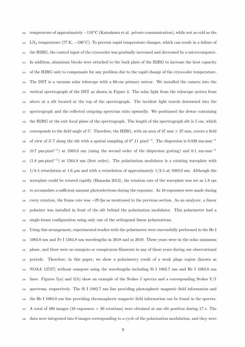
Using this arrangement, experimental studies with the polarimeter were successfully performed in the He I229
1083.0 nm and Fe I 1564.8 nm wavelengths in 2018 and in 2019. These years were in the solar minimum230
phase, and there were no sunspots or conspicuous filaments in any of these years during our observational231
periods. Therefore, in this paper, we show a polarimetry result of a weak plage region (known as232
NOAA 12727) without sunspots using the wavelengths including Si I 1082.7 nm and He I 1083.0 nm233
lines. Figures 5(a) and 5(b) show an example of the Stokes I spectra and a corresponding Stokes V/I234
spectrum, respectively. The Si I 1082.7 nm line providing photospheric magnetic field information and235
the He I 1083.0 nm line providing chromospheric magnetic field information can be found in the spectra.236
A total of 480 images (16 exposures × 30 rotations) were obtained at one slit position during 17 s. The237
data were integrated into 8 images corresponding to a cycle of the polarization modulation, and they were238
9

converted to a set of images presenting Stokes signals. Even though the data were taken with insufficient239
light intensity, the noise level of the Stokes signals is as low as 3× 10⁻³; because the signal-to-noise ratio240
is mainly limited by the photon statistics, a lower noise level is expected with a sufficient number of241
photons. In the Stokes V/I spectrum (Figure 5(b)), remarkable Zeeman polarization signals in the Si I242
1082.7 nm line and weak Zeeman signals both in the blue (1082.91 nm) and red (1083.03 nm) components243
of the He I 1083.0 nm line can be seen. We acquired such spectral data at 26 slit positions separated at244
every 2′′; as a result, we obtained polarization data of a two-dimensional field of view of 3′.7× 52′′.245
Figure 5(c) shows a Stokes V/I map of Si I 1082.7 nm of this field of view, which represents the246
photospheric longitudinal magnetic field of the weak plage region. The black and white patterns247
correspond to a bipolar magnetic polarity distribution (negative and positive polarities, respectively)248
in the plage region. Figure 5(d) shows a longitudinal magnetogram obtained by the Helioseismic and249
Magnetic Imager (HMI; Scherrer et al. 2012) of the Solar Dynamics Observatory (SDO; Pesnell et al.250
2012) including the same area. The HMI uses photospheric magnetic field data based on the Fe I 617.3 nm251
line. It is confirmed that results from the HMI magnetic field map and the Stokes V/I map recorded252
with the infrared camera are in good agreement.253
The result of this experiment confirms the high polarimetric performance of the new infrared camera.254
Nevertheless, certain problems, such as the degradation of the image quality due to the noise from the255
cryocooler, have been revealed. This noise is a kind of electromagnetic interferences, which increases in256
proportion to the output of the cryocooler (the data shown in Figure 5 were taken while the cryocooler257
was turned off). Now we are improving the grounding and the isolation to cope with this noise. After258
addressing these problems, the camera will be introduced to regular observations.259
Conclusions260
We successfully constructed a polarimeter system with a H2RG array by Teledyne, which is a large-261
format, high-speed, near-infrared detector suitable for solar polarimetry. Although it has been difficult262
to synchronize H2RGs under fast readout mode with external devices, such as a polarization modulator,263
we solved this problem by introducing a MACIE card and relevant assembly codes provided by Markury264
Scientific. With this development, advanced solar polarimetry is realized, which will enable the tracking265
of the evolution of the magnetic field in solar filaments, which occasionally erupt and develop into CMEs.266
The synchronous operation of the SIDECAR/H2RG with an external device under fast readout mode267
10

can be realized using an existing SIDECAR/H2RG without preparing a new, dedicated camera system.268
Only the addition of a set of a MACIE card and assembly codes is required. Therefore, the technology269
of this camera system can be widely applied in near-infrared solar polarimetry.270
List of abbreviations271
HAWAII-2RG: H2RG; frames per second: fps; Markury ASIC Control and Interface Electronics: MACIE;272
Tenerife Infrared Polarimeter: TIP; Coronal Mass Ejections: CMEs; National Astronomical Observatory273
of Japan: NAOJ; analog-to-digital: A/D; System for Image Digitization, Enhancement, Control And274
Retrieval: SIDECAR; SIDECAR Acquisition Module: SAM; Application-Specific Integrated Circuit:275
ASIC; Personal Computer: PC; Complex Programmable Logic Device: CPLD; Correlated Double276
Sampling: CDS; Domeless Solar Telescope: DST; Helioseismic and Magnetic Imager: HMI; Solar277
Dynamics Observatory: SDO.278
Availability of data and materials279
The datasets generated during the current study are not publicly available because they are for experi-280
mental purpose; however they are available from the corresponding author on reasonable request.281
Competing interests282
The authors declare that they have no competing interests.283
Funding284
This work is supported by a Japanese Kakenhi grant 15H05814, “Project for Solar-Terrestrial Environ-285
ment Prediction” and also by a NAOJ research grant.286
Authors’ contributions287
YH led the development of the infrared camera. YKat was the point of contact to Teledyne and Markury288
Scientific. MS worked on assembling and experiments, YKam contributed to establishing the cryogenic289
performance of the dewar, and NI performed experiments for the temperature control of the dewar. All290
authors read and approved the final manuscript.291
11

Acknowledgments292
The camera system was developed and tested with the support of the Advanced Technology Center of293
the NAOJ. The authors thank Markus Loose from Markury Scientific for his help in successfully294
implementing the MACIE to the H2RG and the SIDECAR ASIC. The Hida Observatory of Kyoto295
University accepted our proposal for the experimental observations, and the observations were carried296
out with the support of the staff of Hida Observatory. We thank the SDO team for providing the HMI297
data; SDO is a mission for NASA’s Living With a Star program. We would like to thank Editage298
(www.editage.com) for English language editing.299
References300
Blank R, Anglin S, Beletic JW, Bhargava S, Bradley R, Cabelli CA, Chen J, Cooper D, Demers R,301
Eads M, Farris M, Lavelle W, Luppino G, Moore E, Piquette E, Ricardo R, Xu M, Zandian M (2012)302
H2RG focal plane array and camera performance update. In: Holland AD Beletic JW (eds) Proc.303
SPIE High Energy, Optical, and Infrared Detectors for Astronomy V. 8453:845310-1-16.304
doi:10.1117/12.926752305
Chen J, Loose M, Ricardo R, Beletic J, Farris M, Xu M, Wong A, Cabelli C (2014) SIDECAR ASIC306
firmware for astronomy applications. In: Proc. SPIE High Energy, Optical, and Infrared Detectors for307
Astronomy VI. 9154:915426-1. doi:10.1117/12.2056481308
309
Collados M, Lagg A, Dıaz Garcıa JJ, Hernandez Suarez E, Lopez Lopez R, Paez Mana E, Solanki SK310
(2007) Tenerife Infrared Polarimeter II. In: Heinzel P Dorotovic I Rutten RJ (eds) The Physics of311
Chromospheric Plasmas, ASP Conference Series 368:611-616.312
313
Collados M, Lopez R, Paez E, Hernandez E, Reyes M, Calcines A, Ballesteros E, Dıaz JJ, Denker C,314
Lagg A, Schlichenmaier R, Schmidt W, Solanki SK, Strassmeier KG, von der Luhe O, Volkmer R315
(2012) GRIS: The GREGOR Infrared Spectrograph. Astronomische Nachrichten 333:872-879. doi:316
10.1002/asna.201211738317
Hanaoka Y (2012) Polarimeter with a high-speed rotating waveplate for the solar observation. In:318
McLean IS Ramsay SK Takami H (eds) Proc. SPIE Ground-based and Airborne Instrumentation for319
Astronomy IV. 8446:844670-1-8. doi:10.1117/12.925304320
12

Hanaoka Y, Katsukawa Y, Morita S, Kamata Y, Ishizuka N (2019) Development of an Infrared Camera321
Using a Hawaii-2RG Detector for Solar Polarimetry. In: Gandorfer A Lagg A Raab K (eds)322
Proceedings of the 9th Solar Polarization Workshop SPW9. doi:10.17617/2.3194859323
Hanaoka Y, Sakurai T (2017) Statistical Study of the Magnetic Field Orientation in Solar Filaments.324
Astrophys J 851:130-1-11. doi:10.3847/1538-4357/aa9cf1325
Harvey J, Hall D (1975) Magnetic Field Observations with Fe I λ15648 A. Bull. American Astronomical326
Society 7:459327
328
Jaeggli SA, Lin H, Mickey DL, Kuhn JR, Hegwer SL, Rimmele TR, Penn MJ (2010) FIRS: a new329
instrument for photospheric and chromospheric studies at the DST. Mem. S.A.It. 81:763-768.330
Lagg A (2007) Recent advances in measuring chromospheric magnetic fields in the He I 10830 A line.331
Adv Space Res 39:1734-1740. doi:10.1016/j.asr.2007.03.091332
333
Lagg A, Lites B, Harvey J, Gosain S, Centeno R (2017) Measurements of Photospheric and334
Chromospheric Magnetic Fields. Space Sci. Rev. 210:37-76. doi:10.1007/s11214-015-0219-y335
Loose M, Smith B, Alkire G, Joshi A, Kelly D, Siskind E, Mann S, Chen J, Askarov A, Fox-Rabinovitz336
J, Leong E, Goodwin A, Lindsay D, Rossetti D, Mah J, Cheng E, Miko L, Culver H, Wollack E,337
Content D (2018) The ACADIA ASIC: detector control and digitization for the Wide-Field Infrared338
Survey Telescope (WFIRST). In: Proc. SPIE Astronomical Telescopes + Instrumentation.339
10709:107090T. doi:10.1117/12.2313067340
341
Martinez Pillet V, Collados M, Sanchez Almeida J, Gonzalez V, Cruz-Lopez A, Manescau A, Joven E,342
Paez E, Diaz J, Feeney O, Sanchez V, Scharmer G, Soltau D (1999) LPSP & TIP: Full Stokes343
Polarimeters for the Canary Islands Observatories. In: Rimmele TR, Balasubramaniam KS, Radick344
RR (eds) High Resolution Solar Physics: Theory, Observations, and Techniques, ASP Conference345
Series 183:264-272.346
Mosby, G, Eggen N, Wolf M, Jaehnig K, Kotulla R (2016) Persistence characterization and data347
calibration scheme for the RSS-NIR H2RG detector on SALT. In: Proc. SPIE 9915:99152U.348
doi:10.1117/12.2233227349
Nakai Y, Hattori A (1984) Domeless Solar Tower Telescope at the Hida Observatory. Mem Fac Sci350
13

Kyoto Univ Series of Phys Astrophys Geophys Chem 36:385-399351
Penn MJ (2014) Infrared Solar Physics. Living Reviews in Solar Physics 11:2. doi:10.12942/lrsp-2014-2352
Pesnell WD, Thompson BJ, Chamberlin PC (2012) The Solar Dynamics Observatory (SDO). Solar353
Phys 275:3-15. doi:10.1007/s11207-011-9841-3354
Sakurai T, Hanaoka Y, Arai T, Hagino M, Kawate T, Kitagawa N, Kobiki T, Miyashita M, Morita S,355
Otsuji K, Shinoda K, Suzuki I, Yaji K, Yamasaki T, Fukuda T, Noguchi M, Takeyama N, Kanai Y,356
Yamamuro T (2018) Infrared spectro-polarimeter on the Solar Flare Telescope at NAOJ/Mitaka.357
Publ Astron Soc Japan 70:58-1-58-17. doi:10.1093/pasj/psy050358
Scherrer PH, Schou J, Bush RI, Kosovichev AG, Bogart RS, Hoeksema JT, Liu Y, Duvall TL, Zhao J,359
Title AM, Schrijver CJ, Tarbell TD, Tomczyk S (2012) The Helioseismic and Magnetic Imager (HMI)360
Investigation for the Solar Dynamics Observatory (SDO) Solar Phys 275:207-227.361
doi:10.1007/s11207-011-9834-2362
14
H2RGSIDECAR
PC
Dewar
Polarization Modulator+Analyzer
Timing Controller
Incident Light
motor drive pulse
origin signal
row clockexternal trigger
origin signal
(cryogenic)
MACIE Card
Ca
me
raL
ink
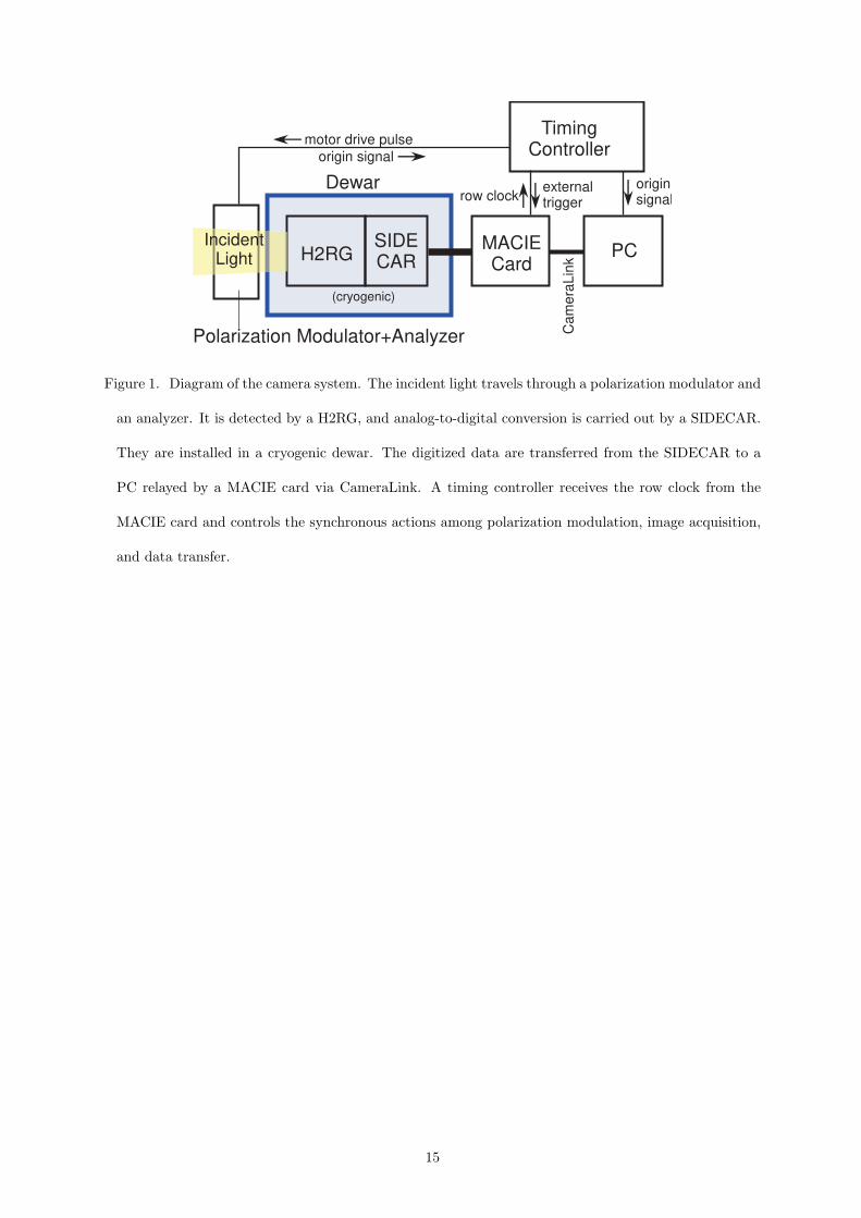
Figure 1. Diagram of the camera system. The incident light travels through a polarization modulator and
an analyzer. It is detected by a H2RG, and analog-to-digital conversion is carried out by a SIDECAR.
They are installed in a cryogenic dewar. The digitized data are transferred from the SIDECAR to a
PC relayed by a MACIE card via CameraLink. A timing controller receives the row clock from the
MACIE card and controls the synchronous actions among polarization modulation, image acquisition,
and data transfer.
15

rese
t
row=1
row=window size
read
read
read
rese
t
rese
t
Drive Pulses for the Stepper Motor
Polarization Modulator (Stepper Motor+Rotating Waveplate)
Origin Signal
Timing ControllerReceives row clock Generate drive pulses for the motor and external trigger signals
Drive pulses for the stepper motor ExtTrig x 25Hz
External Trigger 29, 59, 117Hz, etc.
External TriggerRow Clock
Sends out row clock Receives external trigger signals and read out data via SIDECAR
row clock about 70 kHz
Exposure Time
H2RG A cycle of exposure = 1/29, 1/59, 1/117 sec etc. = row clock x 2400, 1200, 600 etc.
SIDECAR
MACIE Card
Origin signal
Figure 2. Timing chart of the synchronous system including the timing controller, the polarization
modulator, and the SIDECAR/MACIE with the H2RG.
16
0 2000 4000 6000 80002000
2200
2400
2600
2800
3000
0 2000 4000 6000 8000Row Clock
2000
2200
2400
2600
2800
3000
Inte
nsity
(ar
bitr
ary
scal
e)
0 100 200 300Rotation Angle (degree)
Q/I=1
U/I=1
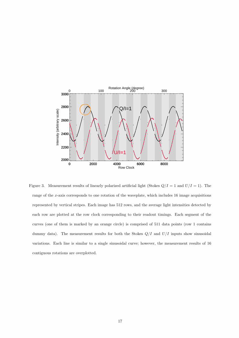
Figure 3. Measurement results of linearly polarized artificial light (Stokes Q/I = 1 and U/I = 1). The
range of the x-axis corresponds to one rotation of the waveplate, which includes 16 image acquisitions
represented by vertical stripes. Each image has 512 rows, and the average light intensities detected by
each row are plotted at the row clock corresponding to their readout timings. Each segment of the
curves (one of them is marked by an orange circle) is comprised of 511 data points (row 1 contains
dummy data). The measurement results for both the Stokes Q/I and U/I inputs show sinusoidal
variations. Each line is similar to a single sinusoidal curve; however, the measurement results of 16
contiguous rotations are overplotted.
17

Rotating waveplate in front of the slit
MACIE card and peripheral electronicsOutgoing Spectrum
Incident Light
Dewar
Cryocooler
Vertical Spectrograph Housing
Figure 4. Experimental arrangement of the H2RG camera system in the Domeless Solar Telescope. The
instruments were deployed on the top-table of the vertical spectrograph. Close-ups of the rotating
waveplate and the MACIE card are also shown.
18
-0.02
0.00
0.02
800 850 900 950 1000
0
50
100
150
200
Si I 1082.7
He I 1083.0(a) Stokes I (b) Stokes V/I (c) Map
(d) SDO/HMI Magnetogram
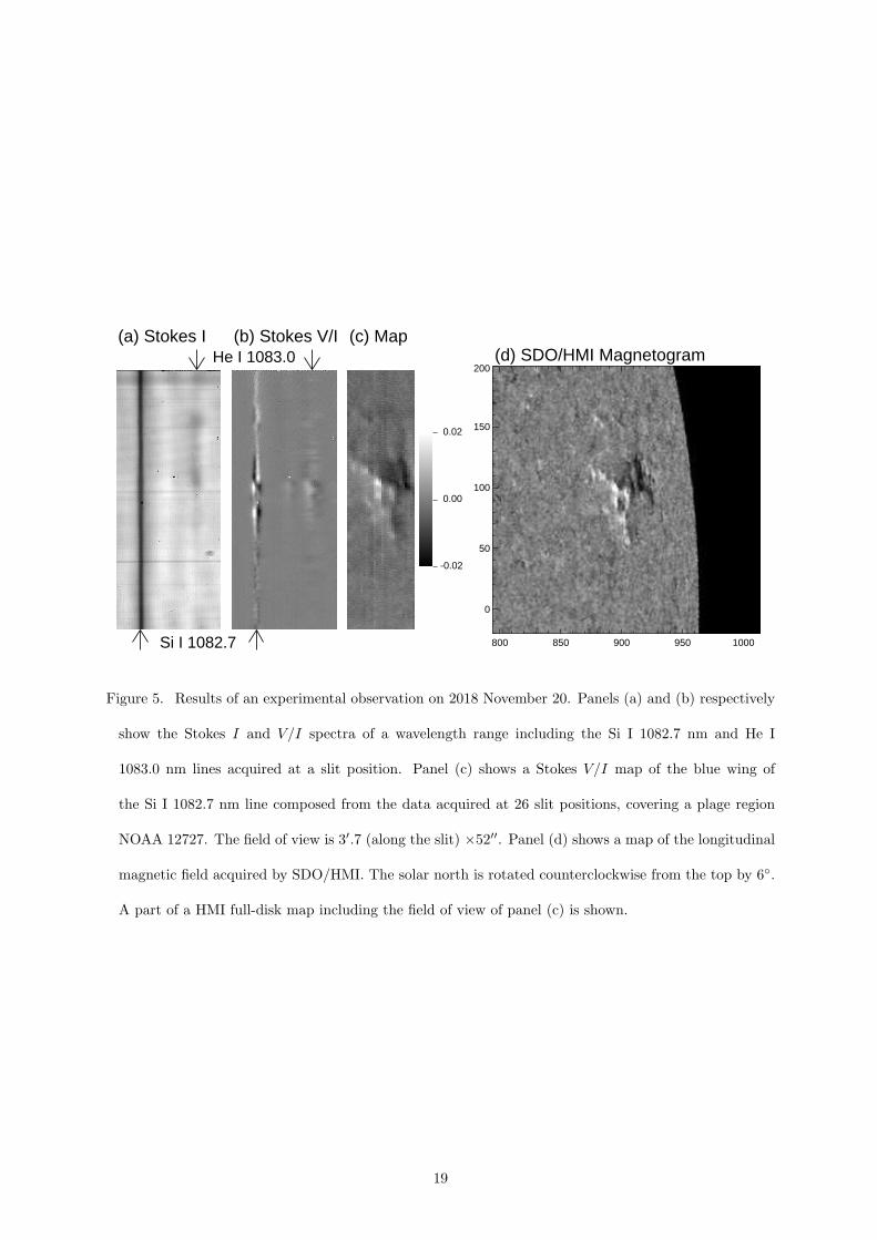
Figure 5. Results of an experimental observation on 2018 November 20. Panels (a) and (b) respectively
show the Stokes I and V/I spectra of a wavelength range including the Si I 1082.7 nm and He I
1083.0 nm lines acquired at a slit position. Panel (c) shows a Stokes V/I map of the blue wing of
the Si I 1082.7 nm line composed from the data acquired at 26 slit positions, covering a plage region
NOAA 12727. The field of view is 3′.7 (along the slit) ×52′′. Panel (d) shows a map of the longitudinal
magnetic field acquired by SDO/HMI. The solar north is rotated counterclockwise from the top by 6◦.
A part of a HMI full-disk map including the field of view of panel (c) is shown.
19
Figures
Figure 1
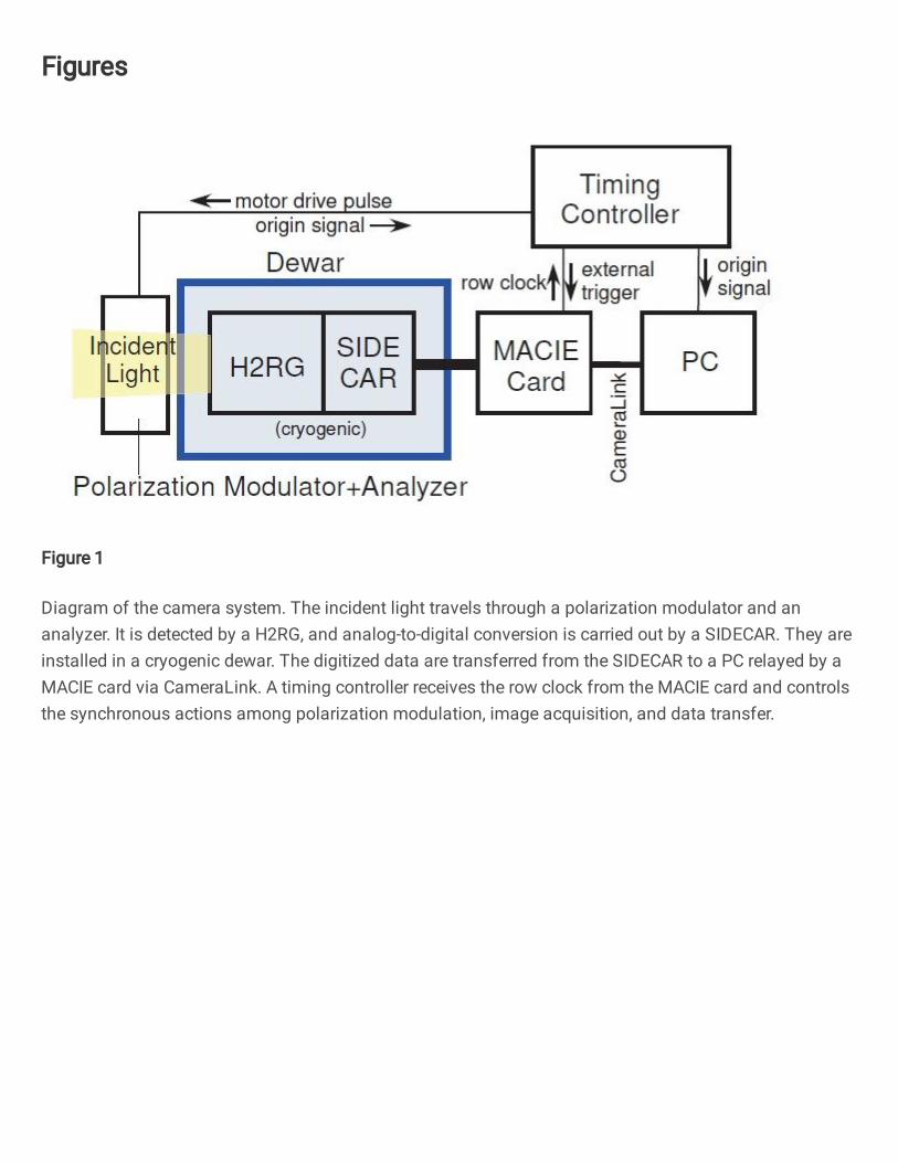
Diagram of the camera system. The incident light travels through a polarization modulator and ananalyzer. It is detected by a H2RG, and analog-to-digital conversion is carried out by a SIDECAR. They areinstalled in a cryogenic dewar. The digitized data are transferred from the SIDECAR to a PC relayed by aMACIE card via CameraLink. A timing controller receives the row clock from the MACIE card and controlsthe synchronous actions among polarization modulation, image acquisition, and data transfer.
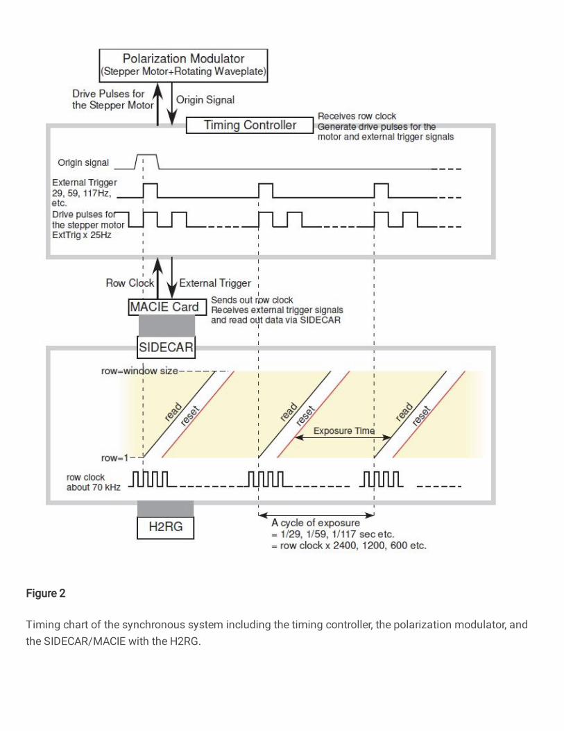
Figure 2
Timing chart of the synchronous system including the timing controller, the polarization modulator, andthe SIDECAR/MACIE with the H2RG.
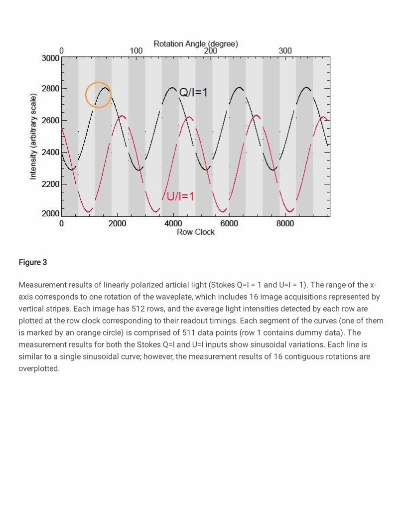
Figure 3
Measurement results of linearly polarized arti cial light (Stokes Q=I = 1 and U=I = 1). The range of the x-axis corresponds to one rotation of the waveplate, which includes 16 image acquisitions represented byvertical stripes. Each image has 512 rows, and the average light intensities detected by each row areplotted at the row clock corresponding to their readout timings. Each segment of the curves (one of themis marked by an orange circle) is comprised of 511 data points (row 1 contains dummy data). Themeasurement results for both the Stokes Q=I and U=I inputs show sinusoidal variations. Each line issimilar to a single sinusoidal curve; however, the measurement results of 16 contiguous rotations areoverplotted.

Figure 4
Experimental arrangement of the H2RG camera system in the Domeless Solar Telescope. Theinstruments were deployed on the top-table of the vertical spectrograph. Close-ups of the rotatingwaveplate and the MACIE card are also shown.

Figure 5
Results of an experimental observation on 2018 November 20. Panels (a) and (b) respectively show theStokes I and V=I spectra of a wavelength range including the Si I 1082.7 nm and He I 1083.0 nm linesacquired at a slit position. Panel (c) shows a Stokes V=I map of the blue wing of the Si I 1082.7 nm linecomposed from the data acquired at 26 slit positions, covering a plage region NOAA 12727. The eld ofview is 3′:7 (along the slit) x52′′. Panel (d) shows a map of the longitudinal magnetic eld acquired bySDO/HMI. The solar north is rotated counterclockwise from the top by 6. A part of a HMI full-disk mapincluding the eld of view of panel (c) is shown.
Supplementary Files
This is a list of supplementary �les associated with this preprint. Click to download.
eps.cls
hanaokagraphicalabstract.png
lineno.sty