Embed Size (px)
Citation preview
A Finite Element Solution for Lateral Track Buckling Problem. J. Gallego and D. Gómez-Rey
- 1 -
A FINITE ELEMENT SOLUTION FOR THELATERAL TRACK BUCKLING PROBLEM
by Javier Gallego and David Gómez-ReyDepartment of Railways Systems’ Technology
TIFSA-Grupo RENFEMadrid, ESPAÑA
Telephone: +34 91 555 95 62Fax: +34 91 555 10 41
Abstract:
People and freight transport have increased in the last few years. With the introductionof CWR several problems caused by traditional tracks have been solved, but new oneshave arisen.The CWR track lateral instability generated by thermal and mechanical loads, due totemperature changes and the pass of vehicles respectively, is one of the most criticaltroubles because the circulation becomes unsafe and causes catastrophic derailments.In the past traditional theoretical analysis were developed for solving track buckling butthey were not appropriated enough for modelling actual situations due to the hypothesisintroduced. Although there was not a general theory accepted by researches, theyapplied traditional results to cases like on curves of more than 500 m radius.The fast development of computers in recent years has made it possible that nowadaysinvestigations can be based on the finite element methods (F.E.M).A non-linear, three-dimensional finite element study of lateral track buckling ispresented to solve traditional limitations. Lateral ballast resistance and rail lifting wavedue to vertical loads generated by the pass of vehicles are considered as they are themost influential parameters, are considered.The finite element model has been developed for tight, metric curves, particularly, forless than 150 meters curves radius where the problem of lateral track buckling becomescritical.As a conclusion of the investigations, values of buckling temperatures have beenobtained in order to predict lateral track buckling. Figures comparing results fordifferent radius, lateral resistance and defect of alignment are also included.Final theoretical results shall be validated with field tests.
A Finite Element Solution for Lateral Track Buckling Problem. J. Gallego and D. Gómez-Rey
- 2 -
1. Introduction:
Widespread introduction of Continuous Welded Rails (CWR), instead of the traditionaljointed ones, has caused an increase of accidents and incidents due to track bucklingproblems, that is why nowadays this phenomena has become more interesting.
Track buckling can be caused only by thermal loads due to temperature changes or bymixture of thermal and mechanical loads generated by the pass of vehicles (dynamicbuckling). [1]
In the past were developed different analytical methods but they used to be verycomplex mathematically and with lot of disadvantages.[7] [8] Later in time differentfinite element models were programmed to study track buckling. [2] [4]
In this survey, finite element models have been developed to eliminate disadvantages ofthe previous methods.
The presented models are non-linear. There is one for the vertical direction and other forlateral direction, being the vertical direction results used in the lateral one. They havebeen generated with multi-purpose packaged software for simulating tight metriccurves, this is, curves with a radius between 100 and 150 meters where track buckling isbeing increased.
Multi-purpose finite element packaged software have been strongly developed and theyinclude powerful numeric resolution methods, that is why this kind of software hasbecome very useful for solving complex mathematical problems like track buckling.
The purpose of this packaged software modelling is to find a simple way to predict trackbuckling. The important point of this model is the determination and the evaluation ofthe track parameters that will affect the problem’s solution, this is the generation of themodel.
The following parameters have been considered in this model:
� Lateral resistance.
� Longitudinal resistance. This parameter does not seem to be very influential so atypical value has been chosen.[2]
� Vertical resistance.
� Simulated and Non-simulated track interaction.
� Rail lifting wave.
� Initial track geometric imperfections amplitude.
� Curve radius.
� Tie spacing.
� Rail profile.
Torsion resistance has not been considered as advice the sensitive figure shown in [2].
A Finite Element Solution for Lateral Track Buckling Problem. J. Gallego and D. Gómez-Rey
- 3 -
2 . Development of non-linear multi-purpose packagedsoftware generated models:
A finite element packaged software has been used for developing the non-linear models.
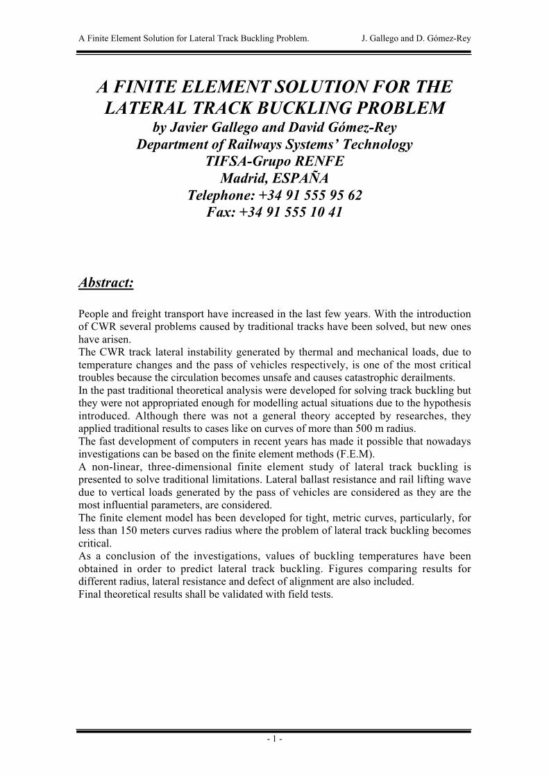
The initial non-linear and three-dimensional model, shown in figure 1, has been dividedin two new models, one for the vertical direction and another for the lateral direction.
Figure 1: Three-dimensional model.
They works as follows:
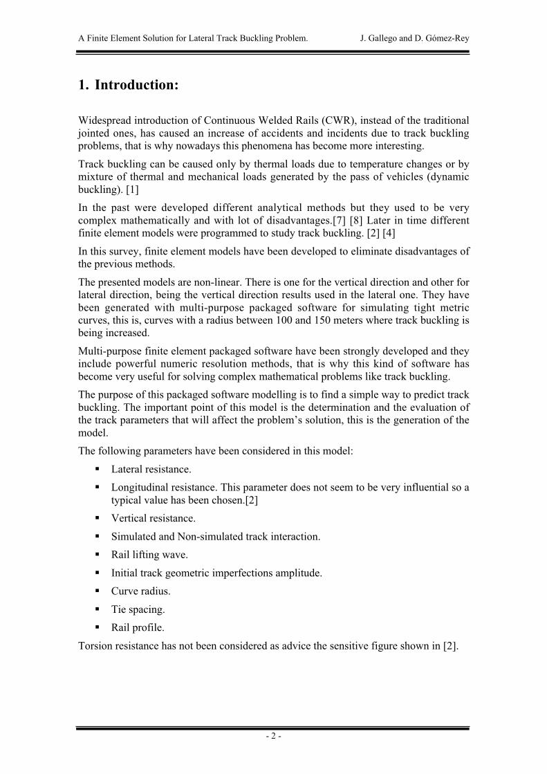
♦ The first model is used for vertical direction modelling. With this one, rail-lifting wave generated by the pass of vehicles has been obtained, this willallow to calculate modified lateral resistance’s values to be introduced insecond model. Figure 2 shows the vehicle characteristics and the static raillifting wave generated. Reduced lateral resistance ties and increased ones canbe identified on figure 2.
Figure 2: Rail lifting wave.
A Finite Element Solution for Lateral Track Buckling Problem. J. Gallego and D. Gómez-Rey
- 4 -
In this first model, thermal loads have not been introduced because thesewill be responsible of lateral track buckling but they will nor havesignificant influence in the rail-lifting wave.
Gap element have been used for modelling the vertical resistance, thoseelements work as the ballast do. When the gap is under compression forceits behaviour is like a spring and if the element is under traction force, railbecome free and gap element can not do anything to keep the rail on itsposition.
The ties have been modelled by rigid elements.
Longitudinal resistance has been modelled by non-linear spring element.
To calculate the rail lifting wave it has been used force control numericalmethods, this means that the force’s evolution followed a control curve thatgrew to the vertical force’s value induced by the vehicles.
♦ The second model is used for lateral direction modelling. Using the raillifting wave calculated with first model and experimental correlation shownin [1], the modified lateral resistance’s values can be calculated and finallyintroduced in lateral model.
Thermal loads have been introduced in this second model. The lateral loadsgenerated for the vehicle must also be introduced but after severalsimulations it can be concluded that this loads did not have a significantinfluence in final results.
Non-linear spring elements have been used for modelling the lateralresistance. Spring’s characteristic curve came from the field tests’ data.
To calculate the critical buckling temperatures it has been used displacementcontrol numerical methods, this means that the displacement’s evolutionfollowed a control curve that grew linearly to the maximum lateraldisplacement’s value simulated. For each iteration, the packaged softwaregave the temperature needed to get the step’s displacement, so at the end thetrack buckling evolution could be drawn.
50 meters track length have been simulated, as the model shown in [2].
3 . Validation of the multi-purpose finite element packagedsoftware generated model:
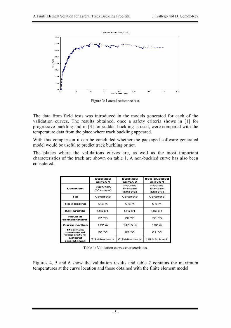
To validate the model, several field tests have been done to obtain the different trackparameters’ values in buckled tracks. A lateral resistance test is shown in figure 3.
A Finite Element Solution for Lateral Track Buckling Problem. J. Gallego and D. Gómez-Rey
- 5 -
Figure 3: Lateral resistance test.
The data from field tests was introduced in the models generated for each of thevalidation curves. The results obtained, once a safety criteria shows in [1] forprogressive buckling and in [3] for sudden buckling is used, were compared with thetemperature data from the place where track buckling appeared.
With this comparison it can be concluded whether the packaged software generatedmodel would be useful to predict track buckling or not.
The places where the validations curves are, as well as the most importantcharacteristics of the track are shown on table 1. A non-buckled curve has also beenconsidered.
Table 1: Validation curves characteristics.
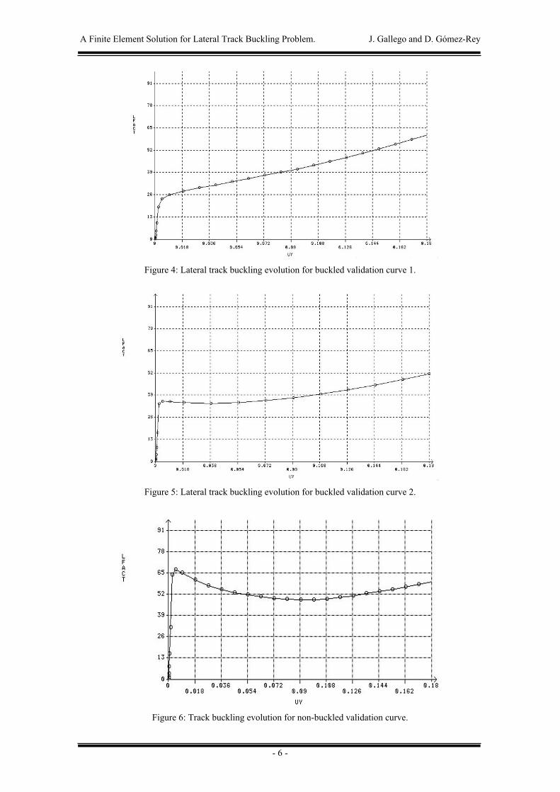
Figures 4, 5 and 6 show the validation results and table 2 contains the maximumtemperatures at the curve location and those obtained with the finite element model.
A Finite Element Solution for Lateral Track Buckling Problem. J. Gallego and D. Gómez-Rey
- 6 -
Figure 4: Lateral track buckling evolution for buckled validation curve 1.
Figure 5: Lateral track buckling evolution for buckled validation curve 2.
Figure 6: Track buckling evolution for non-buckled validation curve.
A Finite Element Solution for Lateral Track Buckling Problem. J. Gallego and D. Gómez-Rey
- 7 -
Table 2: Validation results.
From the validation figures it can be stated that the finite element packaged softwaregenerated model would have predicted track buckling properly in the case of buckledcurves.
For a non-buckled curve, the model would have also given an appropriate result,predicting that track buckling would have not appeared.
4. Practical application:
In the last few years accidents and incidents due to track buckling, particularly in tightcurves, have increased. Some abacuses have been prepared to study the problem.
UIC 54 track with 0.6m tie spacing has been used.
Curve radius between 100 and 150 meters have been used.
For each of the curve radius, three initial track geometric imperfection amplitude levelshave been modelled by a half-sine wave, to sum up, 10, 20 and 50mm.
Finally for each of the three amplitude levels of initial track geometric imperfection, 8different lateral resistance levels have been considered: 7, 8, 10, 12, 14, 16, 18 and 20kN per meter of track.
Therefore 96 simulations, that will fill most of the tight curves situations, have beenmade.
The practical application of the finite element model included let obtain the followingresults:
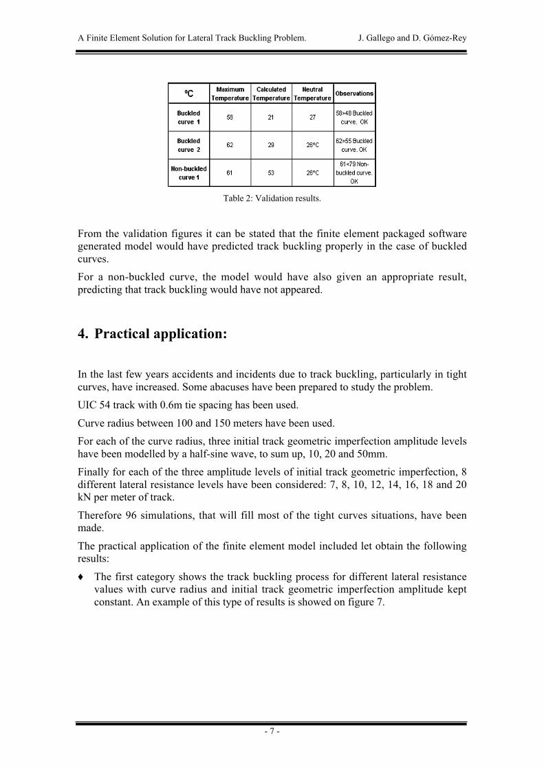
♦ The first category shows the track buckling process for different lateral resistancevalues with curve radius and initial track geometric imperfection amplitude keptconstant. An example of this type of results is showed on figure 7.
A Finite Element Solution for Lateral Track Buckling Problem. J. Gallego and D. Gómez-Rey
- 8 -
Figure 7: First category of results.
It can be concluded that when the lateral resistance value is increased, criticalbuckling temperatures also increase and the buckling process changes formprogressive buckling to sudden buckling appearing then both, the upper andlower, critical buckling temperatures.
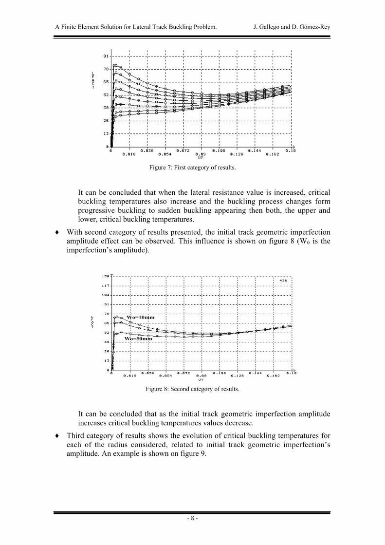
♦ With second category of results presented, the initial track geometric imperfectionamplitude effect can be observed. This influence is shown on figure 8 (W0 is theimperfection’s amplitude).
Figure 8: Second category of results.
It can be concluded that as the initial track geometric imperfection amplitudeincreases critical buckling temperatures values decrease.
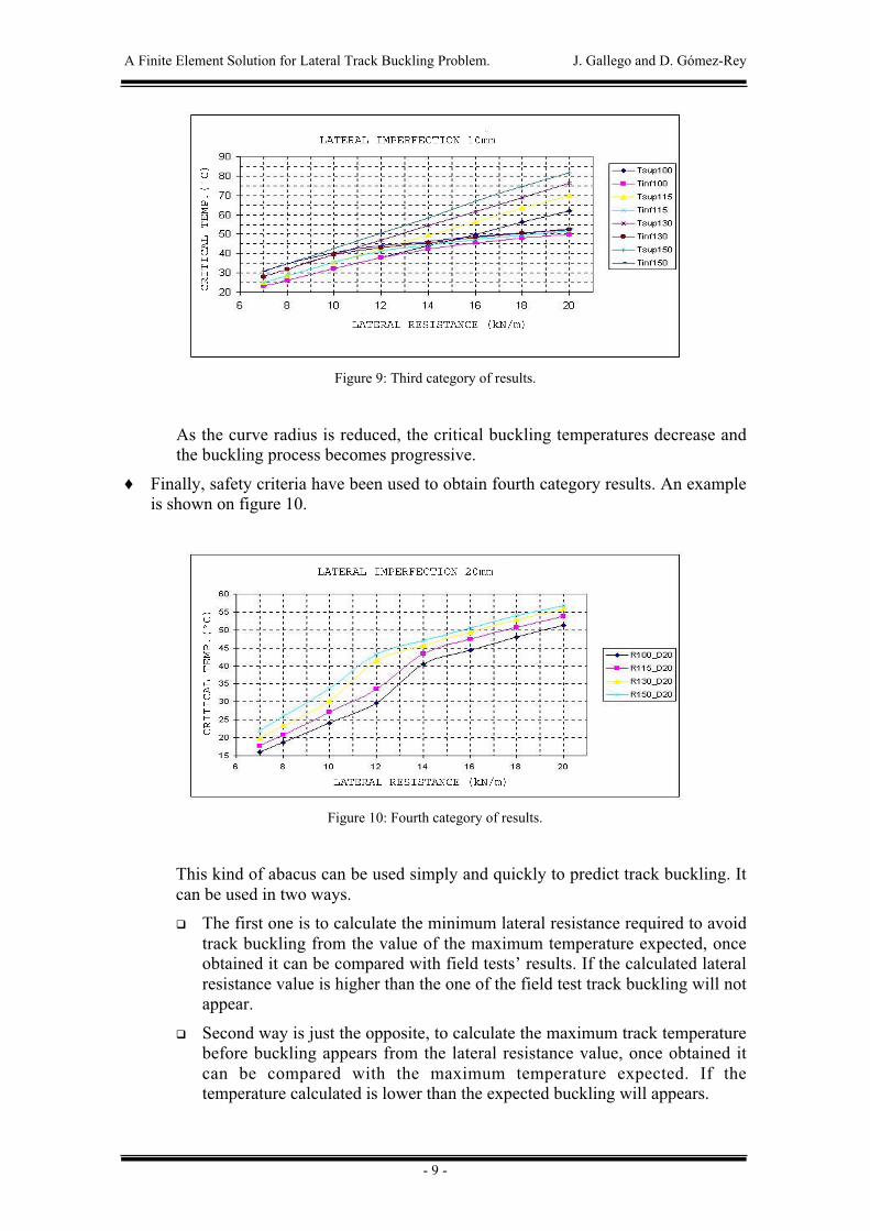
♦ Third category of results shows the evolution of critical buckling temperatures foreach of the radius considered, related to initial track geometric imperfection’samplitude. An example is shown on figure 9.
A Finite Element Solution for Lateral Track Buckling Problem. J. Gallego and D. Gómez-Rey
- 9 -
Figure 9: Third category of results.
As the curve radius is reduced, the critical buckling temperatures decrease andthe buckling process becomes progressive.
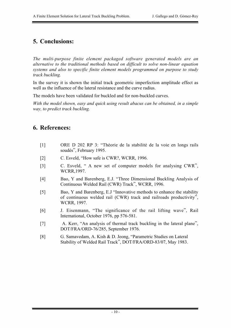
♦ Finally, safety criteria have been used to obtain fourth category results. An exampleis shown on figure 10.
Figure 10: Fourth category of results.
This kind of abacus can be used simply and quickly to predict track buckling. Itcan be used in two ways.
� The first one is to calculate the minimum lateral resistance required to avoidtrack buckling from the value of the maximum temperature expected, onceobtained it can be compared with field tests’ results. If the calculated lateralresistance value is higher than the one of the field test track buckling will notappear.
� Second way is just the opposite, to calculate the maximum track temperaturebefore buckling appears from the lateral resistance value, once obtained itcan be compared with the maximum temperature expected. If thetemperature calculated is lower than the expected buckling will appears.
A Finite Element Solution for Lateral Track Buckling Problem. J. Gallego and D. Gómez-Rey
- 10 -
5. Conclusions:
The multi-purpose finite element packaged software generated models are analternative to the traditional methods based on difficult to solve non-linear equationsystems and also to specific finite element models programmed on purpose to studytrack buckling.
In the survey it is shown the initial track geometric imperfection amplitude effect aswell as the influence of the lateral resistance and the curve radius.
The models have been validated for buckled and for non-buckled curves.
With the model shown, easy and quick using result abacus can be obtained, in a simpleway, to predict track buckling.
6. References:
[1] ORE D 202 RP 3: “Théorie de la stabilité de la voie en longs railssoudés”, February 1995.
[2] C. Esveld, “How safe is CWR?, WCRR, 1996.
[3] C. Esveld, “ A new set of computer models for analysing CWR”,WCRR,1997.
[4] Bao, Y and Barenberg, E.J. “Three Dimensional Buckling Analysis ofContinuous Welded Rail (CWR) Track”, WCRR, 1996.
[5] Bao, Y and Barenberg, E.J “Innovative methods to enhance the stabilityof continuous welded rail (CWR) track and railroads productivity”,WCRR, 1997.
[6] J. Eisenmann, “The significance of the rail lifting wave”, RailInternational, October 1976, pp 576-581.
[7] A. Kerr, “An analysis of thermal track buckling in the lateral plane”,DOT/FRA/ORD-76/285, September 1976.
[8] G. Samavedam, A. Kish & D. Jeong, “Parametric Studies on LateralStability of Welded Rail Track”, DOT/FRA/ORD-83/07, May 1983.