Embed Size (px)
Citation preview
A FINITE-ELEMENT METHOD FOR BENDING ANALYSIS
OF LAYERED STRUCTURAL SYSTEMS
by
Wayne B. Ingram Hudson Matlock
Research Report Number 56-5
Development of Methods for Computer Simulation of Beam-Columns and Grid-Beam and Slab Systems
Research Project 3-5-63-56
conducted for
The Texas Highway Department
in cooperation with the U. S. Department of Transportation
Federal Highway Administration Bureau of Public Roads
by the
CENTER FOR HIGHWAY RESEARCH
THE UNIVERSITY OF TEXAS
AUSTIN, TEXAS
June, 1967
The op1n1ons, findings, and conclusions expressed in this publication are those of the authors and not necessarily those of the Bureau of Public Roads.
ii

PREFACE
This report is the fifth in a series of developments planned to enhance
the use of computers in the analysis of highway bridge structures. It is
concerned specifically with the bending analysis of a layered structural
system, such as a grid overlying a series of parallel beams or a plate over
parallel beams. A large group of structures, including portions of highway
bridges, falls into this category. This report will provide research back
ground for use in later programs which will consider more layers and other
parameters such as shear interaction between layers.
This work is a part of Research Contract No. 3-5-63-56, entitled
"Development of Methods for Computer Simulation of Beam-Columns and Grid-Beam
and Slab Systems." It forms an extension to methods previously reported in
Reports No. 56-1 and 56-4 and the method presented in Ref 29.
The computer programs included in this report are written in FORTRAN 63
language for the CDC 1604 or 6600 computers. With minor changes, the program
would be compatible with the IBM 7090 or 360 systems. Duplicate copies of the
program decks and test data cards for the example problems in this report may
be obtained from the Center for Highway Research at The University of Texas.
The support of this work by the Texas Highway Department and the U. S.
Bureau of Public Roads is acknowledged. Particular thanks are due to Mr.
Larry G. Walker, who acted as project contact representative. The use of the
computer and facilities of The University of Texas Computation Center has
contributed significantly to this report.
iii
Wayne B. Ingram
Hudson Matlock

!!!!!!!!!!!!!!!!!!!"#$%!&'()!*)&+',)%!'-!$-.)-.$/-'++0!1+'-2!&'()!$-!.#)!/*$($-'+3!
44!5"6!7$1*'*0!8$($.$9'.$/-!")':!
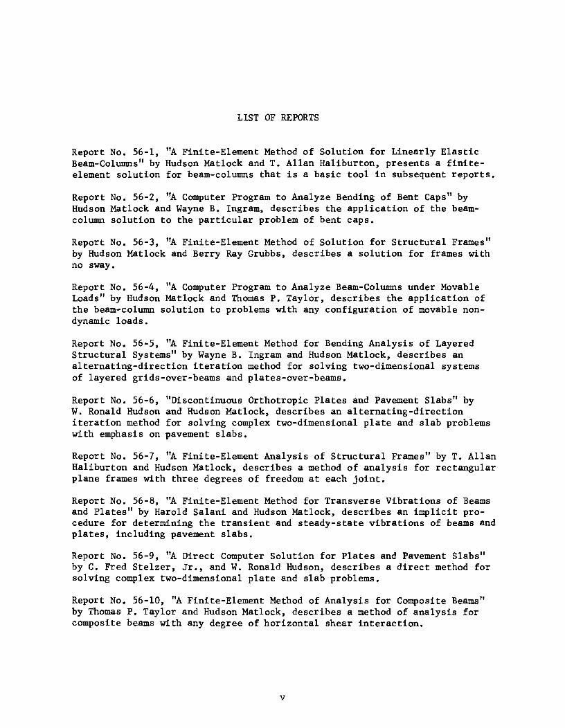
LIST OF REPORTS
Report No. 56-1, "A Finite-Element Method of Solution for Linearly Elastic Beam-Columns" by Hudson Matlock and T. Allan Haliburton, presents a finiteelement solution for beam-columns that is a basic tool in subsequent reports.
Report No. 56-2, "A Computer Program to Analyze Bending of Bent Caps" by Hudson Matlock and Wayne B. Ingram, describes the application of the beamcolumn solution to the particular problem of bent caps.
Report No. 56-3, "A Finite-Element Method of Solution for Structural Frames" by Hudson Matlock and Berry Ray Grubbs, describes a solution for frames with no sway.
Report No. 56-4, "A Computer Program to Analyze Beam-Columns under Movable Loads" by Hudson Matlock and Thomas P. Taylor, describes the application of the beam-column solution to problems with any configuration of movable nondynamic loads.
Report No. 56-5, "A Finite-Element Method for Bending Analysis of Layered Structural Systems" by Wayne B. Ingram and Hudson Matlock, describes an alternating-direction iteration method for solving two-dimensional systems of layered grids-over-beams and plates-over-beams.
Report No. 56-6, "Discontinuous Orthotropic Plates and Pavement Slabs" by W. Ronald Hudson and Hudson Matlock, describes an alternating-direction iteration method for solving complex two-dimensional plate and slab problems with emphasis on pavement slabs.
Report No. 56-7, "A Finite-Element Analysis of Structural Frames" by T. Allan Haliburton and Hudson Matlock, describes a method of analysis for rectangular plane frames with three degrees of freedom at each joint.
Report No. 56-8, "A Finite-Element Method for Transverse Vibrations of Beams and Plates" by Harold Salani and Hudson Matlock, describes an implicit procedure for determining the transient and steady-state vibrations of beams and plates, including pavement slabs.
Report No. 56-9, "A Direct Computer Solution for Plates and Pavement Slabs" by C. Fred Stelzer, Jr., and W. Ronald Hudson, describes a direct method for solving complex two-dimensional plate and slab problems.
Report No. 56-10, "A Finite-Element Method of Analysis for Composite Beams" by Thomas P. Taylor and Hudson Matlock, describes a method of analysis for composite beams with any degree of horizontal shear interaction.
v

!!!!!!!!!!!!!!!!!!!"#$%!&'()!*)&+',)%!'-!$-.)-.$/-'++0!1+'-2!&'()!$-!.#)!/*$($-'+3!
44!5"6!7$1*'*0!8$($.$9'.$/-!")':!
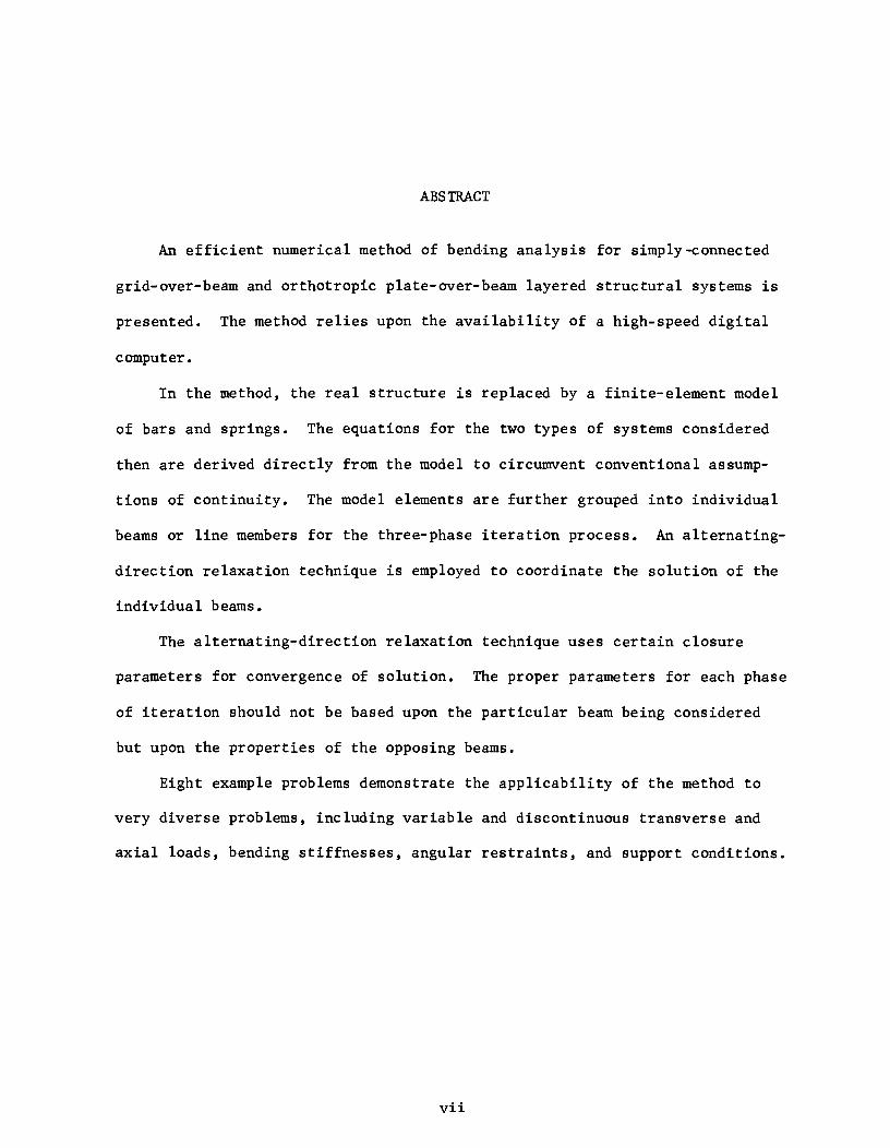
ABSTRACT
An efficient numerical method of bend,ing analysis for simply-connected
grid-over-beam and orthotropic plate-over-beam layered structural systems is
presented. The method relies upon the availability of a high-speed digital
computer.
In the method, the real structure is replaced by a finite-element model
of bars and springs. The equations for the two types of systems considered
then are derived directly from the model to circumvent conventional assump
tions of continuity. The model elements are further grouped into individual
beams or line members for the three-phase iteration process. An alternating
direction relaxation technique is employed to coordinate the solution of the
individual beams.
The alternating-direction relaxation technique uses certain closure
parameters for convergence of solution. The proper parameters for each phase
of iteration should not be based upon the particular beam being considered
but upon the properties of the opposing beams.
Eight example problems demonstrate the applicability of the method to
very diverse problems, including variable and discontinuous transverse and
axial loads, bending stiffnesses, angular restraints, and support conditions.
vii

!!!!!!!!!!!!!!!!!!!"#$%!&'()!*)&+',)%!'-!$-.)-.$/-'++0!1+'-2!&'()!$-!.#)!/*$($-'+3!
44!5"6!7$1*'*0!8$($.$9'.$/-!")':!
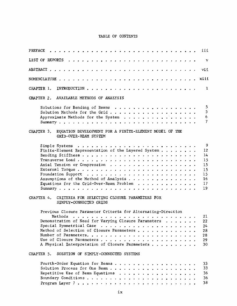
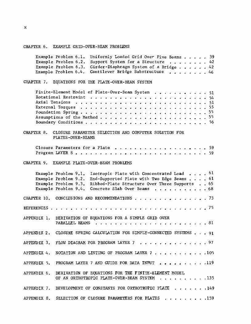
TABLE OF CONTENTS
PREFACE
LIST OF REPORTS
ABSTRACT . .
NOMENCIAWRE .
CHAPTER 1. INTRODUCTION.
CHAPTER 2. AVAILABLE METHODS OF ANALYSIS
Solutions for Bending of Beams Solution Methods for the Grid • Approximate Methods for the System Summary . • . . • . • • • .
CHAPTER 3. EQUATION DEVELOPMENT FOR A FINITE-ELEMENT MODEL OF THE GRID-OVER-BEAM SYSTEM
Simple Systems •..•.•.•.•••.•..•.•. Finite-Element Representation of the Layered System. . • . • • Bending Stiffness . • • • . . Tran sverse Load . • . . • . . . Axial Tension or Compression External Torque . . . . . Foundation Support . • . . . Assumptions of the Method of Analysis . Equations for the Grid-Over-Beam Problem Summary . . • . • . . . . . . . • . .
CHAPTER 4. CRITERIA FOR SELECTING CLOSURE PARAMETERS FOR SIMPLY-CONNECTED GRIDS
Previous Closure Parameter Criteria for Alternating-Direction Me thod s . . • . • . • • . • . • • ~ • _ . .
Demonstration of Need for Varying Closure Parameters Special Symmetrical Case . . . . . • . • • Method of Selection of Closure Parameters • Number of Parameters. • . Use of Closure Parameters • . . . . . . . A Physical Interpretation of Closure Parameters .
CHAPTER 5. SOLUTION OF SIMPLY-CONNECTED SYSTEMS
Fourth-Order Equation for Beams . Solution Process for One Beam . • • . • • • Repetitive Use of Beam Equations • • • • . . • . • Boundary Conditions •••• Program Layer 7 • • • • • • • • •
ix
iii
v
vii
xiii
1
5 5 6 7
9 12 14 15 15 15 15 16 17 19
21 22 24 28 28 29 30
33 33 36 36 38
x
CHAPTER 6. EXAMPLE GRID-OVER-BEAM PROBLEMS
Example Problem 6.1. Example Problem 6.2. Example Problem 6.3. Example Problem 6.4.
Uniformly Loaded Grid Over Five Beams . Support System for a Structure Girder-Diaphragm System of a Bridge . Cantilever Bridge Substructure • .
CHAPTER 7. EQUATIONS FOR THE PLATE-OVER-BEAM SYSTEM
Finite-Element Model of P1ate-Over-Beam System Rotational Restraint Axial Tensions
39 42
· 42 · . 46
51 · • 54
· 51 External Torques · • . . 55 Foundation Spring Assumptions of the Method Boundary Conditions . . . • .
CHAPTER 8. CLOSURE PARAMETER SELECTION AND COMPUTER SOLUTION FOR PLATES-OVER-BEAMS
Closure Parameters for a Plate Program LAYER 8 • • • • • • . • •
CHAPTER 9. EXAMPLE PLATE-OVER-BEAM PROBLEMS
Example Problem 9.1. Example Problem 9.2. Example Problem 9.3. Exampie Problem 9.4.
Isotropic Plate with Concentrated Load End-Supported Plate with Two Edge Beams Ribbed-Plate Structure Over Three Supports Concrete Slab Over Beams • . • • .
CHAPTER 10. CONCll]SIONS AND RECOMMENDATIONS •
55 55 56
59 • 59
61 .61
• . 65 • 68
73
REFERENCES . · . • • 75
APPENDIX 1. DERIVATION OF EQUATIONS FOR A SIMPLE GRID OVER PARALLEL BEAMS . . . . • . . . • . . . . . . . · • 81
APPENDIX 2. CLOSURE SPRING CALCULATION FOR SIMPLY-CONNECTED SYSTEMS. • 91
APPENDIX 3. FLOW DIAGRAM FOR PROGRAM LAYER 7 97
APPENDIX 4. NOTATION AND LISTING OF PROGRAM LAYER 7 . • .105
APPENDIX 5.
APPENDIX 6.
APPENDIX 7.
PROGRAM LAYER 7 AND GUIDE FOR DATA INPUT . . . . . . . DERIVATION OF EQUATIONS FOR THE FnnTE-ELEMENT MODEL OF AN ORTHOTROPIC PLATE-OVER-BEAM SYSTEM . • . •
DEVELOPMENT OF CONSTANTS FOR ORTHOTROPIC PLATE
· .
APPENDIX 8. SELECTION OF CLOSURE PARAMETERS FOR PLATES
.119
.135
.149
.159
xi
APPENDIX 9. FLOW DIAGRAM FOR PROGRAM LAYER 8 • 165
APPENDIX 10. NOTATION AND LISTING OF PROGRAM LAYER 8 • • 173
APPENDIX 11. PROGRAM LAYER 8 AND GUIDE FOR DATA INPUT • 189
APPENDIX 12. SAMPLE INPUT AND OUTPUT FOR PROGRAM LAYER 7 • • 205
APPENDIX 13. SAMPLE INPUT AND OUTPUT FOR PROGRAM LAYER 8 • • 233

!!!!!!!!!!!!!!!!!!!"#$%!&'()!*)&+',)%!'-!$-.)-.$/-'++0!1+'-2!&'()!$-!.#)!/*$($-'+3!
44!5"6!7$1*'*0!8$($.$9'.$/-!")':!
Symbol
A
A ••• E i i
a .••• n. ~ ~
a
b
C
E
F
G
G n
H
h
I
i
j
K
K e
k
L
M
Typical Units
lb/ ina
in.
in.
lb/in
lb/in
in.
in-lb
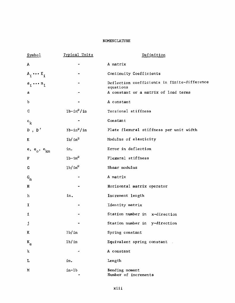
NOMENCLATURE
Definition
A matrix
Continuity Coefficients
Deflection coefficients in finite-difference equations A constant or a matrix of load terms
A constant
Torsional stiffness
Constan t
Plate flexural stiffness per unit width
Modulus of elasticity
Error in deflection
Flexural stiffness
Shear modulus
A matrix
Horizontal matrix operator
Increment length
Identity matrix
Station number in x-direction
Station number in y-direction
Spring constant
Equivalent spring constant
A constant
Length
Bending moment Number of increments
xiii
xiv
Symbol
M'
m
n
P
pi
6,p
Q
q
R
r
S
SF
SY
s
T
T. T ~ n
t
V
Vi
v
w , w
x, y, z
z
a, 13
I3n
TYEical Units
in-Ib/in
lb
lb/in
lb
lb
lb/in
in-lb/rad
in-Ib/in/rad
lb/in
lb/in
lb/in
Ib/in2
in-Ib
in-Ib/in or in.
Ib or ...
lb/in
in.
in.
degrees
Definition
Bending moment per unit width
Number of closure parameters
A constant = M - I
Axial tension (+) or compression (-)
Axial force per unit width
Change in axial force
Concentrated applied transverse load
Applied transverse load per unit length
Concentrated rotational spring restraint
Rotational restraint per unit length
Concentrated transverse spring restraint
Fictitious closure spring
Natural closure spring
Transverse spring restraint per unit length
Concentrated applied torque
A matrix
Applied torque per unit length Thickness of plate
Shear or Vertical matrix operator
Shear per unit width
Eigenvector
Transverse deflection
Direction
Distance from neutral axis of member
Angles used in derivation of closure equations
An angle
xv
Symbol Typical Units Definition
e in/in Strain
e Central-difference slope
r- An eigenvalue
J..L An eigenvalue
v An eigenvalue or Poisson I s ratio
TT radian The constant pi 3.14159
1T Infinite product
p Closure parameter
cr lb/ inS Normal stress
cp Simple-difference slope
CHAPTER 1. INTRODUCTION
This study concerns a rational numerical method for the bending analysis
of layered structural systems. A layered structural system is a structure
composed of members which overlay and are supported by other members which may
in turn be supported by still other members. An example of a layered structure
is the floor system of a highway bridge. A bridge generally is composed of a
plate or slab which is supported by girders that are connected laterally by
diaphragms and which rest on a support such as a bent cap. Thus, a bridge can
be visualized as a three-deep system of structural elements: a series of bent
caps, a gridwork composed of girders and diaphragms, and a plate or slab.
Some other layered structures include slabs-on-foundations, building founda
tions, aircraft structures, ship hulls, and sign boards.
The analysis of such systems usually is simplified so that a single par
tial differential equation may be used for an approximate analysis. For in
stance, conventional solutions reduce the system to a simple gridwork or plate
for which the equations are well known. These solutions at best contain
restrictions which are undesirable. Closed-form solutions of differential
equations are restricted to systems which have simple shapes and continuous
or very nearly continuous functions for loading, support conditions, and
bending stiffness. The numerical approximations to these differential
equations are likewise limited. The previously stated example of a layered
structural system does not necessarily conform to restrictions of continuity,
and thus a better solution for such common systems is desirable.
The layered system is conducive to a difference-equation solution. How
ever, when difference equations are used for the solution of such systems,
large numbers of simultaneous algebraic equations may result. The solving of
1
2
such large numbers of equations by classical methods is difficult if not im-
possible. Methods such as matrix inversion or relaxation usually are much too
slow or require excessive amounts of computer storage capacity.
Presented herein is a numerical method for the analysis of layered struc-
tura1 systems which is efficient. The method contains almost complete genera1-
ity regarding both transverse and in-plane forces, flexural stiffness, and
support conditions.
The method is based on the following four items:
(1) replacement of the layered structural system by a finite-element model of each layer - only vertical connections are considered between layers;
(2) a difference-equation formulation of equations for solving individual beams on elastic foundations;
(3) an alternating-direction relaxation technique for coordination of individual beam solutions - three layers of beams are solved, one layer in each phase of solution; and
(4) a process whereby each individual beam solution considers the response of each opposing beam to obtain information needed for solution of the entire system.
The contributions of this study are in four areas. First, a concept of
solving structures more realistically as layered systems, rather than approxi-
mating the behavior as that of a single grid or plate, is developed and present-
ed herein. Second, a finite-element model concept is extended to solve the
system. Third, the applicability of a relaxation method previously used for
grids and simple isotropic plates is extended to the solution of layered
systems, even those involving orthotropic plates. Fourth, the concept of
substitution of loads and springs for each opposing member in the system is
presented as a means of obtaining an efficient solution for very diverse
systems •

3
Chapter 2 discusses previous methods of solution which are applicable to
the layered system. Chapter 3 discusses the development of the equations for a
simply-connected gridwork over a series of parallel beams. The method of
selection of closure parameters for the alternating-direction technique is
developed in Chapter 4. Chapter 5 shows the arrangement of the solution and
discusses the computer program written to solve the equations developed in
Chapter 2. Example problems of simply-connected grids over parallel beams are
included in Chapter 6 to indicate the generality and capability of the method.
Chapter 7 indicates the differences between a simply-connected grid and
a plate and develops the equations for an orthotropic-p1ate-over-beam system.
Closure parameters for orthotropic-p1ate-over-beam systems and the computer
program which solves the system are discussed in Chapter 8. Example solutions
to problems of orthotropic plates over parallel beams are presented in Chapter
9.
Conclusions concerning the method of analysis are presented in Chapter 10
with recommended extensions of the method.

!!!!!!!!!!!!!!!!!!!"#$%!&'()!*)&+',)%!'-!$-.)-.$/-'++0!1+'-2!&'()!$-!.#)!/*$($-'+3!
44!5"6!7$1*'*0!8$($.$9'.$/-!")':!
CHAPTER 2. AVAILABLE METHODS OF ANALYSIS
Numerous methods are available for the solution of the individual elements
of the layered structural system. The elements consist of a Simply-connected
gridwork or a plate and a series of parallel beams. Several of these methods
will be discussed in this chapter.
Solutions for Bending of Beams
The use of difference equations derived from a finite-element model fur
nishes one means of solution for the bending of beams which is readily adaptable
to digital computer techniques. Such a method has been developed by Matlock
(Ref 20) for the solution of beam-columns on elastic foundations. The details
of this method have been given by Matlock and Ingram (Ref 23), Matlock and
Haliburton (Ref 22) and others (Refs 10, 17). The essentials of this
method of beam solution which are used in solving the layered system will be
summarized in Chapter 5.
Solution Methods for the Grid
At the present time, iteration techniques appear to be the most efficient
means of solving a grid system when the number of mesh points is large.
Numerous relaxation methods are available which involve the judicious selection
of initial estimates for unknown values and improving these estimates as the
solution progresses from mesh point to mesh point in the selected region.
Over-relaxation methods are available which require the determination of
relaxation parameters to speed up the solution. Unfortunately the expressions
for the parameters are quite complicated and considerable time is required for
their determination.
Successful alternating-direction iteration techniques have been presented
5
6
by Conte and Dames (Ref 6) and Peaceman and Rachford (Ref 25). The alter
nating-direction scheme involves successive solutions of the ordinary differ
ential equation for a beam. The solution of the grid would be accomplished
by solving a system of beams in one direction and then a system of beams in
the other direction with a coupling procedure at the points of intersection.
Convergence of solution generally is assured and accelerated by appropriate
selection of one or more closure parameters. These closure parameters will be
discussed in detail in Chapter 4.
Tucker (Ref 29) applied the Conte and Dames procedure for the biharmonic
equation to simply connected grids and simple isotropic plates with a good
degree of success. Tucker gave a physical interpretation of the closure param
eters but used the Conte and Dames procedure of cycling a parameter several
times before selection of another for several cycles of solution.
Two unpublished methods (Ref 34) are available for the solution of
gridworks. One is concerned with orthogonal systems while the second concerns
a random1y-oriented gridwork of beams. Both of these methods consider only
transverse loading, spring supports, and varying bending stiffness.
Approximate Methods for the System
Jenson (Ref 18) and Chen, Seiss, and Newmark (Ref 3) have presented
specialized equations for skewed plate-beam systems. The equations involve
the LaPlace equation as applied to a plate and the conventional fourth order
derivative expression of a beam. By judiciously combining the effects 9f the
beams into the plate equation, new equations were developed which represented
solutions to the combined system. These equations were quite complicated and
other equations were necessary for special considerations such as a free edge
near a simply supported boundary.
7
Ang and Prescott (Ref 2) have given other difference equations for a
plate-beam system which involve fictitious deflections in the vertical direc
tion at each intersecting point. Schade (Ref 27), Hoppmann (Ref 14), Huffington
(Ref 16); and others (Refs 15, 9) have considered the problem of orthogonally
stiffened plates or variable thickness plates. The analysis of such systems in
volved the combination of the stiffnesses of the stiffening members into the
stiffness of the plate and the solution of the simpler problem of an approxi
mately orthotropic plate.
Chu and Krishnamoorthy (Ref 4) have studied the case of the orthotropic
plate bridge. Girders are included as stiffeners which furnish the ortho
tropic condition. Vitols, Clifton, and Au (Ref 30) and Clifton, Chang, and Au
(Ref 5) also have considered the orthotropic-plate bridge but by a "more exact"
orthotropic-plate theory involving a single and double sine series solution.
"Torsiona lly soft" and "torsionally stiff" stiffeners are considered.
Summary
Several methods for solving the elements of the layered system have been
discussed. There are several needed improvements to any of these methods for
a solution of the layered structural system. The method necessarily must
properly consider more than two intersecting beams at one common intersection.
Torsional and Poisson's ratio effects of the plate must not affect the solu
tion of the supporting beams. A more efficient closure process for the al
ternating-direction technique must be developed as more interseccing beams
are considered. A random orientation of the supporting beams is desirable
but not essential for this study.

!!!!!!!!!!!!!!!!!!!"#$%!&'()!*)&+',)%!'-!$-.)-.$/-'++0!1+'-2!&'()!$-!.#)!/*$($-'+3!
44!5"6!7$1*'*0!8$($.$9'.$/-!")':!
CHAPTER 3. EQUATION DEVELOPMENT FOR A FINITE-ELEMENT MODEL OF THE GRID-aVER-BEAM SYSTEM
This chapter presents a discussion of very simple layered systems and the
application of conventional differential equations to their solution. The
equations for a three-bearn-deep system are developed from a finite-element
model and pertinent assumptions are noted.
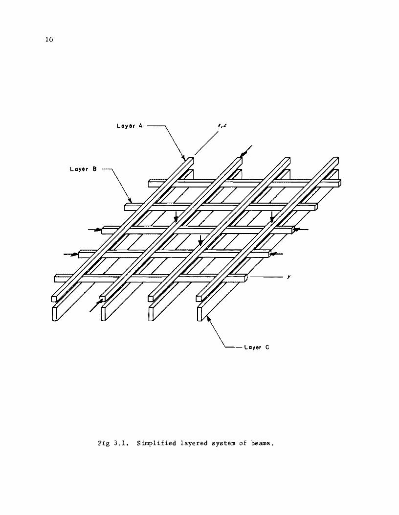
Simple Systems
A very simple layered system supporting a downward and horizontal acting
loading is shown in Fig 3.1. The system is composed of three sets of beams;
the beams in two layers (A and C) are parallel while those in the third layer
(B) are orthogonal to the first two. Layers A and B are two orthogonal sets of
beams and represent a simply-connected gridwork. The third set of beams are
parallel and support the grid. The term "Simply-connected" means that each
intersection of the beams can be visualized as a ball-and-socket connection.
Transverse load is transferred by this connection but otherwise the beams are
independent. The differential equation which governs the solution of a simply-
connected grid, the first two layers of Fig 3.1, has the form of Eq 3.1. Timo-
shenko (Ref 28) uses a form of Eq 3.1 that includes beam torsion:
= q (3.1)
In Eq 3.1, w represents deflection transverse to the plane of the sys-
tern, x and y signify two orthogonal direction~, q is a uniformly dis-
tributed loading over the system, and F is the flexural stiffness (EI) which
is temporarily considered to be a constant for all the beams of the grid. The
o4W term F OX4 represents the load resisted by a beam in the x-direction and
o4W F Oy4 is the load resisted by a beam in the y-direction.
9
10
Layer A x,z
Layer B
Fig 3.1. Simplified layered system of beams.
11
Equation 3.2 governs the solution of the third layer (C) of the system
shown in Fig 3.1 and the terms are analogous to those in Eq 3.1. The z-direction
is the same as the x-direction for this study and any desired spacing of beams
is possible. In practice, the spacing of beams in the third layer usually is
wider than the spacing of the beams in the gridwork.
(3.2)
The solution of the layered system involves solving both Eq 3.1 and Eq 3.2
under the condition that all beams deflect equally at the common intersections.
The system then could be described with a differential equation having the form
of Eq 3.3 since there is only one loading pattern on the system:
(3.3)
Equation 3.3 could be altered slightly because of the assumption of paral-
lelism of layers A and C to have the form
X Z ~4W Y 04W (F + F ) ~X4 + F oy4 = q (3.4)
The usual procedure for the solution of systems of the layered type is to
solve an equation similar to Eq 3.4 with the stiffnesses of the beams combined
with the stiffness of the grid. The ability to maintain the use of Eq 3.3,
with separate consideration of all variables, enhances the possibility of sol-
ving problems of plates-over-beams where it is necessary to include Poisson's
ratio and torsional effects on the plate members and not on the supporting
beams.
Development of finite-difference equations for the solution of a simply-
connected grid-over-beam system will be discussed in the remainder of this
chapter.
12
Finite-Element Representation of the Layered System
The use of finite-element models as representations of physical systems
was discussed by Ang and Newmark (Ref 1) for the solution of plates. The deri-
vation of equations based on a discrete model allows the conventional assump-
tions of continuity of input variable to be circumvented (Ref 2). All approxi-
mations of the physical system are in the discrete model, and the derived
equations are exact for the finite-element system.
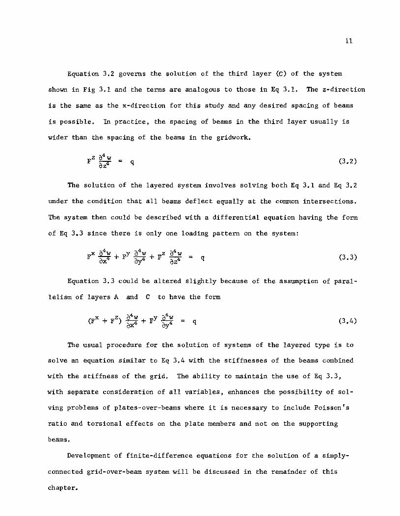
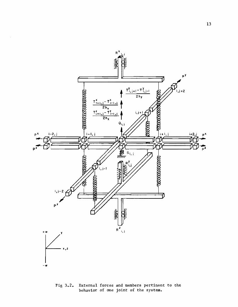
Figure 3.2 shows the forces and members which are pertinent to one joint
of the model where all three layers exist. Nine joints are necessary to describe
two orthogonal beams, and five other joints are necessary to describe the
third beam. The model is composed of rigid bars and joints. The joints are
composed of spring-restrained hinges. All pertinent variables are considered
as lumped values. The bending stiffness F is represented by a spring-
restrained hinge.
The loading system shown in Fig 3.2 is rather general. The Q term rep-
resents a concentrated force at the joint. Py d , an pZ represent axial
tension (or compression) on the respective x, y, and z-members. Change
in axial tension is assumed to occur at the joints. RX, RY , and RZ rep-
resent springs which tend to resist rotation of a joint. The Ty
d , an
TZ terms are representations of externally applied couples and appear as loads
at each Joint adjacent to the Joint in question. The transverse spring S
provides an elastic foundation response or a specified amount of deflection by
using the proper ratio of load Q and spring S. A very large spring would
produce virtually a zero deflection. The Q and S terms refer to the sys-
tem, while all other terms refer to particular beams.
The quantities F Q ,and S are generally distributed effects over
some length or area of the structure. The length over which these effects are
i,j-2
p'
+w y
It X
T1+1,I-Ti-l,j
2h.
Tf+l,j - T~_llj 2hx
t T;;· I-T't· I 1,)+ 1.1-
2hy
t t
z R i,)
i,j+2
1'---- X,Z
w
Fig 3.2. External forces and members pertinent to the behavior of one joint of the system.
13
14
considered to extend includes a length h/2 on each side of a joint. Thus,
the correct usage of distributed effects from one station to another station
necessitates the use of half values at end stations and full values at inter-
mediate stations. Axial tension values P refer to bars rather than joints
and full values should therefore be used throughout. The bar number for which
a P value is described is the same as the joint number ahead of the bar in
the increasing direction of station numbers. Thus, when describing P values
in the x-direction, the station number i=O should not be used or the P
value will be felt outside of the system. Similarly, the station number j=O
should not be used for P values in the y-direction. Rotational restraints
R and torques T usually are needed only as concentrated quantities.
A detailed discussion of the terms just defined is given by Matlock and
Haliburton (Ref 21) as they pertain to an individual beam-column solution. A
brief discussion of each term is given below as it refers to the simp1y-
connected layered system. Equation 3.5 is the general equation for the simp1y-
connected layered system. Lower-case characters t, r, q, and s are
related to the upper-case lumped values T, R, Q, and S by the incre-
ment length h.
FX 04W FY 04W + FZ 04W otX otY otZ a
(rx ~:) ox4 + ~+--+--+-+-oy4 OZ ox oy oz ox
+.2.... oy (ry ~;) +~ oz (rZ ~:) +.2....
ox (px ~:) +~ oy (Py ~;)
+.2.... oz (pZ ~:) = q - sw (3.5)
Bending Stiffness
The bending stiffness F, or EI (product of modulus of elasticity and
cross-sectional area moment of inertia), may vary in a freely discontinuous
manner. A value of F=O creates a hinge or point of zero moment. Two
15
consecutive hinges completely disconnect a beam. Dummy extensions of each
beam, which have no flexural stiffness, act as multiple hinges to isolate the
beam from any effects beyond either end.
Transverse Load
The term Q may be considered as concentrated or distributed. The pres-
ent solution considers only concentrated values so that, if a uniform load is
desired, it must be considered as the product of q, h ,and h where h x y x
and h are increment lengths in orthogonal directions. y
Axial Tension or Compression
Axial tensions (or compressions) are in the rigid bars. A change in
axial tension ~p occurs only in the joints between rigid bars. The terms
in Eq 3.5 representing axial tension could be converted directly to finite-
difference form. However, if this were done, the limitation of constant ten-
sion would be present. Equation 3.6 shows an appropriate discontinuous finite-
difference form for the axial tension. The development of this form is in the
general derivation in Appendix 1.
(3.6)
External Torgue
The external torque is represented as a couple created by forces which
act at stations adjacent to Station i with a magnitude of
ence form for external torque is
at OX =
Foundation Support
T./2h • 1.
The differ-
(3.7)
The foundation support spring S provides both resistance to transverse
16
deflection and a means of deflection control. Virtually zero deflection would
occur with a very large S value. This means of specifying zero deflection
is used to create simple support conditions. A specified value of deflection
can be produced by the proper ratio of Q to S. The term simple support
means a hinge or pin-type support which prevents horizontal or vertical move-
ment but does not resist rotation about the hinge.
The finite-difference equations for the joint of Fig 3.2 can be shown to
have the form
x + bX. . + x + dX + x a. . w. 2 . w. l' c.. w.. ., w·+1 · e.. w'+2 . 1,J 1-,J 1,J 1-,J 1,J 1,J 1,J 1,J 1,J 1 ,J
+ f~ . w. . 2 + g~ . w. . 1 + hY • w. '+1 + i~ . w. '+2 1,J 1,J- 1,J 1,J- 1,J 1,J 1,J 1,J
+ .z + kZ + Z + Z J. . w. 2' .. w. l' t.. w. +1' m.. w. +2 . 1,J 1-,J 1,J 1-,J 1,J 1,J 1,J 1 ,J
= n .. 1,J
(3.8)
where the constants a. . • 1,J
n. . are constants which are functions of the 1,J
properties of the beams, of the loads, and of the restraints on the system.
Equation 3.8 is the finite-difference form of Eq 3.3 or Eq 3.5.
Assumptions of the Method of Analysis
The assumptions embodied in the method must be clearly understood in order
to recognize the approximations of the real physical problem. Pertinent
assumptions are listed below:
(1) There are vertical forces only between the various beams; there is no horizontal shear at the grid-beam interface.
(2) All beams deflect equally at conunon joints.
(3) The bars between joints are rigid and weightless.
(4) Deflections are small; plane sections remain plane after bending.
(5) All loads, including dead loads, are concentrated at the joints; no external forces act directly on the rigid bars.
(6) Axial forces do not produce axial deformations. Changes in axial forces occur at the joints.
(7) The joint is an elastic, orthotropic, and homogeneous material.
(8) There are no torsional moments nor Poisson's ratio effects at the joints nor in the supporting beams.
(9) The size increment is constant on all parallel beams.
(10) All loads and stiffnesses may vary in a freely discontinuous manner.
Equations for the Grid-over-Beam Problem
Equation 3.3 plus the effect of a foundation spring can be rewritten in
17
b 1 · f E 3 9 h QX QY, and QZ hId' d sym 0 ~c orm as q . , were, represent t e oa s res~ste
by the respective x, y, or z-beams and include the effects of special terms
such as R, P and T.
Q. - S.w. ~ ~ ~
(3.9)
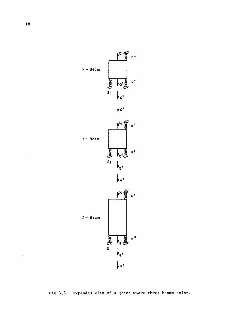
Figure 3.3 shows an expanded view of the joint from the three intersecting
beams in Fig 3.2. The forces shown are the same as for Eq 3.9 except that
. KX spr~gs KY d KZ
, an have been added to appropriate joints. These
springs are temporary representations of the stiffnesses of the beams which
oppose deflections of the particular joint. Thus, if the y and z-beams
were removed from Fig 3.2, their effects on the x-beam would be shown in the
top sketch of Fig 3.3. Summing vertical forces on the three independent joints
in Fig 3.3 results in Eq 3.10. Superscripts indicate which beam the variable
temporarily represents.
18
KZ
X - Beom
KY
Sj , Q'
J Q%
KX
Y - Beom
KZ
Sj
~Q' 'Q%
KY
Z - Beom
Fig 3.3. Expanded view of a jOint where three beams exist.
19
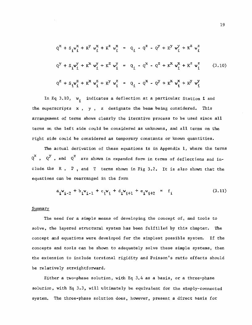
(3.10)
In Eq 3.10, w. ~
indicates a deflection at a particular Station 1 and
the superscripts x, y, z designate the beam being considered. This
arrangement of terms shows clearly the iterative process to be used since all
terms on the left side could be considered as unknowns, and all terms on the
right side could be considered as temporary constants or known quantities.
The actual derivation of these equations is in Appendix 1, where the terms
QX , QY and QZ are shown in expanded form in terms of deflections and in-
clude the R , P , and T terms shown in Fig 3.2. It is also shown that the
equations can be rearranged in the form
a.w. 2 + b.w. 1 + c.w. + diwi +l + e i wi +2 = f. (3.11)
~ ~- ~ ~- ~ ~ ~
Surmnary
The need for a simple means of developing the concept of, and tools to
solve, the layered structural system has been fulfilled by this chapter. The
concept and equations were developed for the simplest possible system. If the
concepts and tools can be shown to adequately solve these simple systems, then
the extension to include torsional rigidity and Poisson's ratio effects should
be relatively straightforward.
Either a two-phase solution, with Eq 3.4 as a basis, or a three-phase
solution, with Eq 3.3, will ultimately be equivalent for the simply-connected
system. The three-phase solution does, however, present a direct basis for

20
solving plate-over-beam problems where only the beams are unaffected by torsion
and Poisson's ratio.
A very important side benefit from the three-phase solution is the accepta
bility of more than two intersecting beams. Previous work in this area of
interest at The University of Texas has been limited to only two intersecting
beams at one point (Ref 34). This ability to properly handle more than two
intersecting beams will allow solution of grids or plates over nonorthogonal
beams even though this application has not been included in this study.
CHAPTER 4. CRITERIA FOR SELECTING CLOSURE PARAMETERS FOR SIMPLY-CONNECTED GRIDS
In Chapter 3, springs were discussed as being repre-
sentative of the stiffnesses of various beams of the system. These spring
stiffnesses also act as closure parameters in the alternating-direction method
of solution. These closure parameters add stability to the system by tending
to hold the system together. The effects of the parameters are nullified at
closure. The structural system considered in this study is generally quite
complex and may involve nonsymmetric matrices. The selection and use of these
closure springs for diverse systems will be discussed in this chapter.
Previous Closure Parameter Criteria for Alternating-Direction Methods
Two of the most frequently used methods of closure parameter selection are
attributed to Wachpress (Ref 31) and Peaceman and Rachford (Ref 25). The
mathematical process used in these two references is quite similar. The process
is valid for cases involving second-order difference equations such as the
LaPlace equation. The two methods assume symmetric matrices and use one
closure parameter in each full cycle of solution. A set of m parameters is
chosen and used in a cyclic manner. Young and Wheeler (Ref 32) have extended
the method of Peaceman and Rachford to consider the case of nonsymmetric
matrices that commute. A proof similar to one of Young and Wheeler's (Ref 32)
will be presented later in support of the criteria to be presented.
Tucker (Ref 29) considered the work of Peaceman and Rachford when applying
the alternating-direction technique to fourth-order difference equations. He
concluded that the closure parameters must stay constant during any iteration
to assure convergence. The criteria presented by Tucker for selection of
fictitious spring stiffnesses predicted a value ck
which could range from 0
21
22
to 1.0 in Eq 4.1:
K = 6F
~~ x
(4.1)
In Appendix 2 it is shown that the product 6ck
theoretically ranges from
o to 16 for simple grid systems but a value of 6 is possibly a practical
maximum.
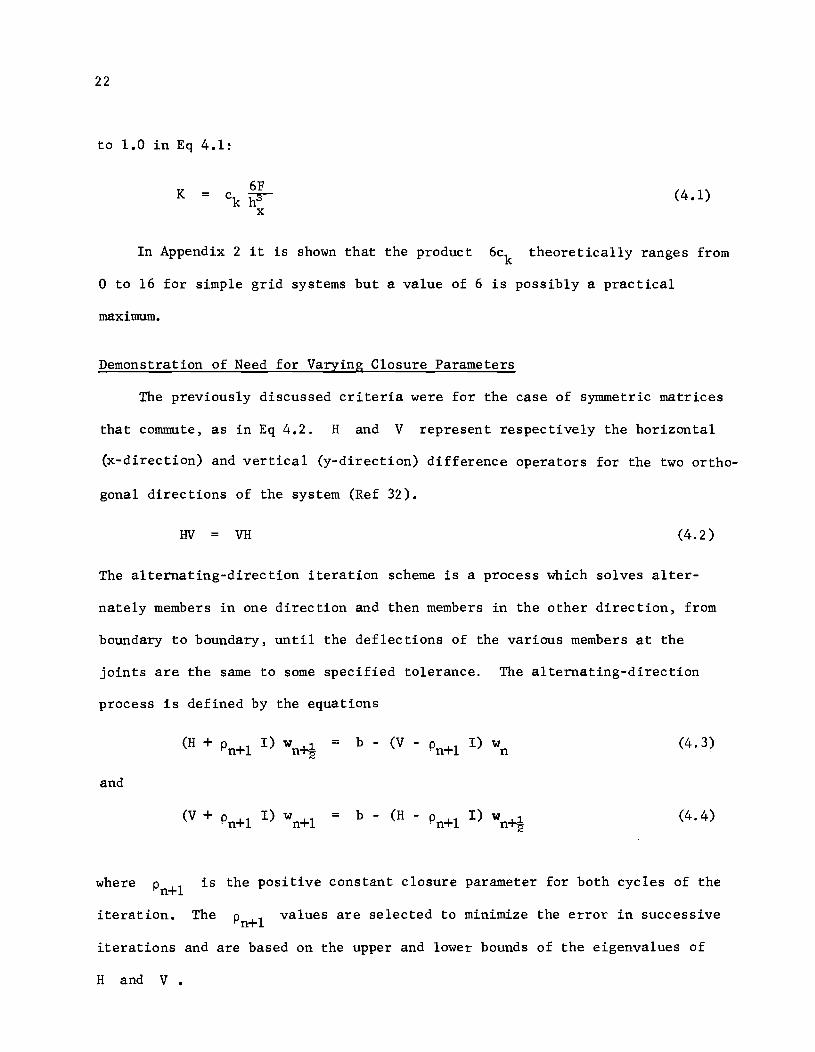
Demonstration of Need for Varying Closure Parameters
The previously discussed criteria were for the case of symmetric matrices
that commute, as in Eq 4.2. H and V represent respectively the horizontal
(x-direction) and vertical (y-direction) difference operators for the two or tho-
gona1 directions of the system (Ref 32).
HV VH (4.2)
The alternating-direction iteration scheme is a process which solves a1ter-
nate1y members in one direction and then members in the other direction, from
boundary to boundary, until the deflections of the various members at the
joints are the same to some specified tolerance. The alternating-direction
process is defined by the equations
= b - (V - Pn+1 I) wn
and
(V + Pn+1 I) wn+1 = b - (H - Pn+1 I) Wn~ (4.4)
where is the positive constant closure parameter for both cycles of the
iteration. The values are selected to minimize the error in successive
iterations and are based on the upper and lower bounds of the eigenvalues of
H and V.
23
The physical structural counterpart for the symmetric case is a structure
composed of equal numbers of beams of equal lengths, stiffnesses, and numbers
of increments in each of the directions of solution. Loads and support condi-
tions must also be symmetric. In the general structural case the condition of
symmetry seldom exists and the eigenvalues for adjacent beams and crossbeams
might vary by factors of thousands. The eigenvalue A for a simply supported
beam can be shown to have the form
= F [ (. ElI)4] h4 16 s~n 2M • (4.5)
This form is developed in Appendix 2 where it also is shown that the
closure parameters for simply-connected grids are related to the eigenvalues.
The relationship is shown in Eq 4.6. SF is the symbol for the fictitious
spring stiffness. The springs are termed fictitious since their effect is
nullified at closure. Variations in bending stiffness F from beam-to-beam
can cause drastic changes in A :
SF = hA (4.6)
The use of upper and lower bounds for both H and V of Eq 4.2 was an
attempt to average the reduction of error for the entire system. A greater
reduction in error can be achieved by allowing each individual beam to recog-
nize the effects of connecting beams. This more efficient solution is obtained
by using SF values for each set of beams in the system rather than one con-
stant SF for the system.
The substitution of a load and closure parameter for each opposing beam at
each intersection of the beam being solved, temporarily simulates the effects of
each replaced beam. This in effect states that the closure parameters to be
considered during the solution of the H matrix should be parameters computed
24
from the V matrix. Similarly, when solving the V matrix the parameters
should be based on the H matrix. A demonstration that this is possible is
in the next section and a step-by-step criteria for the selection of closure
parameters will follow.
Special Symmetrical Case
The alternating-direction iterative process is now defined
as follows:
and
k - (V - P 1. I) n~ w
n
(V + Pn+l I) wn+l
Solving Eq 4.7 for W ~1. and substituting into Eq 4.8 gives n""'2
wn+l =
-1 -1 (V + Pn+l I) k - (V + Pn+l I) (H - Pn+l I)
Or, in notation similar to Young and Wheeler's
wn+l =
where
= -1 -1
(V+Pn+l I) (H-Pn+l I) (H+Pn~ I) (V-Pn~ 1)
and
= -1 [ -lJ (V+P n+ l I) I - (H-Pn+ l I) (H+Pn~ I) .
(4.7)
(4.8)
(4.9)
(4.10)
(4.11)
(4.12)
If the error at the
e = w - w n n
th n iteration is defined as
25
(4.13)
where w is the exact solution of Eq 3.1, then, from Eq 4.10, Eq 4.14 can be
written.
w (4.14)
Substituting Eq 4.10 and 4.14 into Eq 4.13 results in
e = (T w 1 + G k) - (T ; + G k) n n n- n n n (4.15)
which simplifies to
e = T (wn
_1 - w) n n (4.16)
or
e = T e n n n-1 (4.17)
Equation 4.17 implies that the error after n iterations could be written
as
e (T ) (Tn
_1
) (Tn
_2
) ••• (T1
) e n n 0 (4.18)
or
n
e = ( rr Ti ) e n 0 (4.19)
i=l
Now, a set of m parameters is selected (with no requirement that the
parameters be constant during each full cycle) and used in cyclic order so that
for any integer k representing a cycle of the set of m parameters, Eq 4.20
26
is true.
m
ekm = [( rr Ti)kJ eo (4.20)
i=l
For convergence of solution, ekm
must approach zero which implies that
k must approach infinity. Therefore Eq 4.21 must be satisfied.
m
(11 TJ < 1 (4.21)
i=l
According to Young and Wheeler (Ref 33) the H and V matrices have a co~
mon basis of eigenvectors. Let v be one of these eigenvectors, ~ represent
the eigenvalue of V, and ~ represent the eigenvalue of H, so that
and
Hv = ~v
Vv
Then using Eq 4.11, we have
m m
T i rr { (V + Pi I) -1 (H - P i I) (H + P i _~ 1)-1
i=l i=l
x (V - P 'it _~ I)}
Now, an eigenvalue A of
m
AV = (11 Ti
) v
i'-"l
m,
1T T. i=l ~
is sought so that
(4.22)
(4.23)
(4.24)
(4.25)
Substituting the right side of Eq 4.24 into Eq 4.25 and performing the
multiplication by v results in
27
m
f( r -1 -1
AV = ~ (Vv + p.vI) (Hv - p.vI) (Hv + p. lvI) l l l l-2
i=l
(4.26)
Substituting ~v for Hv and vv for Vv results in
m
{-1 -1
AV = f(vv + p.vI) (~v - p.vI) (~v + p. lvI) l l l-2
i=l
(4.27)
Now by dividing out the eigenvector v, Eq 4.28 results:
m (~ - p.) (v - p. V
l l-'2 (4.28) = f(
(~ + i=l
It should be recalled that ~ is an eigenvalue of H and v is an
eigenvalue of V. Equation 4.28 shows that the closure parameter for anyone
particular portion of the solution cycle does not affect only its own corres-
ponding matrix H or V, but that the eigenvalues of both H and V and the
closure parameter on the particular portion of the cycle must be considered.
Thus, considering one term of the product in Eq 4.28 such as ~-p./v+p. , l l
if is much greater than v and if and v are of the same magnitude,
then the ratio will be greater than 1. Thus, divergence is implied where ~
is the eigenvalue of H and Pi is a parameter used in solution of the V
matrix. Consideration of the other term in Eq 4.28 shows that the same re1a-
tion holds where v is an eigenvalue of V and p. l is the parameter used l-2
in solving the H matrix.
Thus to minimize the eigenvalues A,
the v's and should minimize the ~'s
p. l should be chosen to minimize l-2
This implies that one parameter
28
should be chosen for each matrix to be solved and the p for the H solution
should be based on eigenvalues of V and the p for V should be based on
eigenvalues of H.
The arrangement of Eq 4.28 in the form discussed was suggested by Ha1ibur-
ton (Ref 11).
Method of Selection of Closure Parameters
It has been shown that the parameters should be approximations of opposing
systems of beams and that the parameters are related to the eigenvalues of the
opposing systems. The proposed method of selection is outlined below.
(1) Compute eigenvalues from Eq 4.5 for the beams in each layer of the system. If the beams vary in stiffness from end to end, or in the layers, then the highest lower bound and the least upper bound of the eigenvalues should be used for the range of parameters.
(2) Convert eigenvalues to fictitious springs using Eq 4.6.
(3) Select some number of parameters, usually 6 or less, or according to the method outlined in the next section. The selection should cover roughly the range of values from highest lower bound to least upper bound.
(4) Apply the sets of parameters cyc1ic1y and in increasing order.
Number of Parameters
A means of estimating the optimum number of closure parameters to be used
cyc1ic1y was proposed by both Wachpress (Ref 31) and Peaceman and Rachford (Ref
25). The Wachpress method, as applicable to fourth-order systems, is as follows.
Solve Eqs 4.29 and 4.30 for a and b where M is the number of mesh
points in the longest row or column in the system.
a = 16 sin4 1L 2M
(4.29)
29
b = 16 cos4 .IL 2M (4.30)
The number of parameters to cycle is the smallest integer m which
satisfies Eq 4.31.
2m-l <
Use of Closure Parameters
a b
(4.31)
The best sequence of parameters for the layered type problem under con-
sideration seems to be a logarithmic increase. The solution has been found to
be fairly insensitive to the number of parameters, provided that the lower bound
of the eigenvalues is avoided. Usually three to six parameters are a reasonable
number for each layer of the system with the same number being used on all
layers. The range of parameters used usually should cover the lower one-half
of the range from highest lower eigenvalue bound to least upper bound plus one
fairly large value from the upper one-half of the range. It is possible to
develop divergence or oscillation in the solution if the lower bound limit is
not observed. The worst result, for large parameter values, appears to be slow
convergence if the parameters are selected in the upper range or beyond the
upper bound.
Repeating or cycling sequences of parameters has been recommended by
several investigators and appears to be beneficial in reducing the error
between successive iterations of solution. In using the cycling procedure it
is sometimes advisable to let the final parameter in the sequence be a value
between the lowest and highest values of the sequence so that a large change
in condition does not occur instantaneously.
The recommended use of eigenvalues for the selection of fictitious springs
immediately poses the question of various conditions other than simple supports.
30
For the condition of a free-free or unsupported beam, which many of the in-
dividua1 beams are during the first cycle of solution, zero eigenvalues would
theoretically be correct. This aspect has been checked in a computer program
and fortunately, after one cycle of solution, no beams are unsupported; all are
beams on elastic foundations. The cycling procedure brings the zero fictitious
spring into the system again, at which time the solution generally falters. No
extensive checkout has been performed for other conditions of initial beam
support.
A Physical Interpretation of Closure Parameters
The use of eigenvalues to compute closure parameters for the a1ternating-
direction scheme gives good results. An alternate procedure may be intuitively
seen by considering the physical problem. The previously defined terms QX,
QY , and QZ are approximations of the loads which are absorbed by the finite-
element beam. The values of QX, QY, and QZ will vary from station to
station depending on the changes in the deflected shape.
If the system is deflected, then, at each station along each of the beams,
a value of a spring stiffness SY can be computed. This spring is the spring
which will exactly duplicate the deflected shape if the loads applied are the
predicted QX, Qy QZ • , or Equation 4.32 shows the form for the ca1cu1a~
tion of such a spring stiffness for a y-beam.
SY =~ y
w .. (4.32)
1.,J
This is a "natural" spring for the model. Studies have indicated that
negative values of the spring stiffness SY may be computed from Eq 4.32. A
negative spring stiffness may have very adverse effects on the solution. It is
advisable to use a very small positive value rather than a negative value and
31
to add the computed load directly to the system to maintain complete simulation
of the system. Studies have indicated that this "natural" spring concept gives
more rapid deflection closure to a fairly loose tolerance than does the use of
spring stiffnesses based on eigenvalues. Unfortunately, after just a few
cyc les of iterat ion, the further use of the "natural" springs no longer reduces
the error by a significant amount per cycle. It is possible that some combina
tion of the natural spring constant and the eigenvalue spring constant might
produce rapid closure to very tight tolerance. As yet, this combination has
not been determined and the eigenvalue springs will be used to solve the
numerical examples in Chapters 6 and 9.

!!!!!!!!!!!!!!!!!!!"#$%!&'()!*)&+',)%!'-!$-.)-.$/-'++0!1+'-2!&'()!$-!.#)!/*$($-'+3!
44!5"6!7$1*'*0!8$($.$9'.$/-!")':!
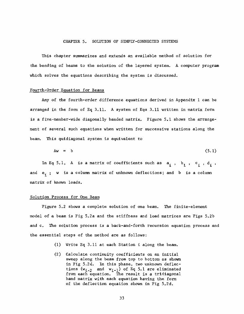
CHAPTER 5. SOLUTION OF SIMPLY -CONNECTED SYSTEMS
This chapter summarizes and extends an available method of solution for
the bending of beams to the solution of the layered system. A computer program
which solves the equations describing the system is discussed.
Fourth-Order Equation for Beams
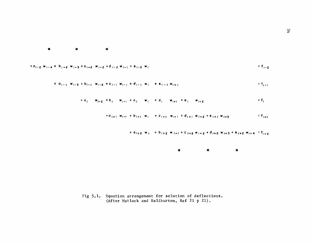
Any of the fourth-order difference equations derived in Appendix 1 can be
arranged in the form of Eq 3.11. A system of Eqs 3.11 written in matrix form
is a five-member-wide diagonally banded matrix. Figure 5.1 shows the arrange-
ment of several such equations when written for successive stations along the
beam. This quidiagonal system is equivalent to
and
Aw = b
In Eq 5.1, A is a matrix of coefficients such as a. , 1.
w is a column matrix of unknown deflections; and b
matrix of known loads.
Solution Process for One Beam
b. , 1.
(5.1)
c. , d. 1. 1.
is a column
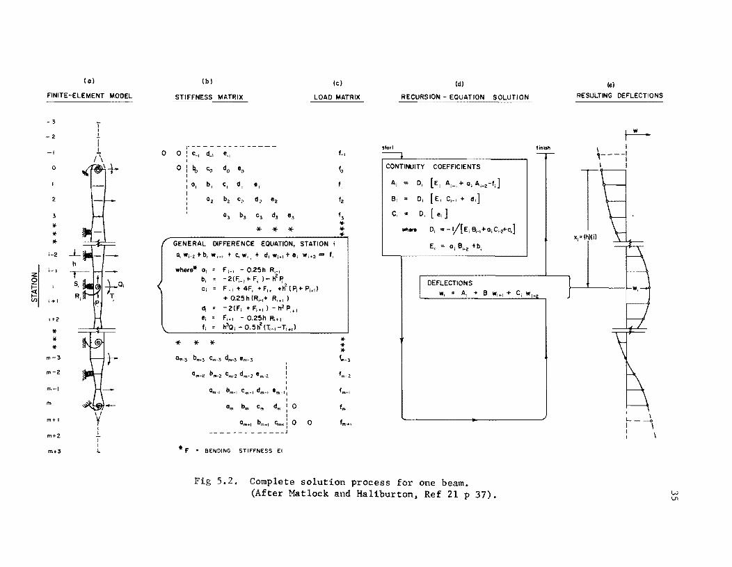
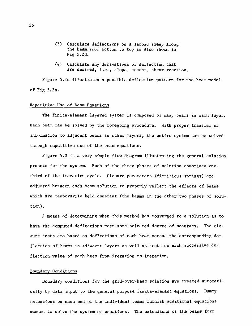
Figure 5.2 shows a complete solution of one beam. The finite-element
model of a beam is Fig 5.2a and the stiffness and load matrices are Figs 5.2b
and c. The solution process is a back-and-forth recursion equation process and
the essential steps of the method are as follows:
(1) Write Eq 3.11 at each Station i along the beam.
(2) Calculate continuity coefficients on an initial sweep along the beam from top to bottom as shown in Fig 5.2d. In this phase, two unknown deflections (wi-2 and wi-l) of Eq 5.1 are eliminated from each equation. The result is a tridiagonal band matrix with each equation having the form of the deflection equation shown in Fig 5.2d.
33
* *
If *
Fig 5.1. Equation arrangement for solution of deflections. (After Matlock and Haliburton, Ref 21 p 21).
= f i-2
= fj
_1
*
(0 )
FINITE-ELEMENT MODEL
-3
2
-I o
0
2
3
If
* II-
i-2
h
Z i- I
0 Si i=
~ Ri (/) 1+1
,+2
* * * m :5
m-2
m-I
m
m+ I
m+2
m+:5
(b)
STIFFNESS MATRIX
r----- -0 ,
C_, ct, '., 0 ,
It Co do '0 , , , 1 0, b, C, d, I , 0, b, C2
°3 b3
" d 2 e2
C3 d3
il- ii-
'3
*
(e)
MATRIX
t,
GENERAL DIFFERENCE EQUATION, STATION i
where' 0,
b, C,
* * *
0,.-,
f i- I - O.25h R,_, -2('i_, to Fi }- h''r
F,., + 4F, .. F", + h2 ( P, to p;.,)
+ O.25h(Ri-I. R,., )
-2(F; • F,.,) - h' Pit' f,., - O.25h R.+, h3Q, _ O.5h
2(li_,-T,+,}
, bm_, C
m_
1 d
m_
1 e ' m-I,
I
am bm Cm dm , 0 I ,
Om ... ! bm., c-: , 0 0 ______ J
• f SENDING STIFFNESS EI
fm
(ti)
RECURSION - EQUATION
starl ----. CONTINUITY COEFFICIENTS
A, = 0, [E, Ai-! + a i A i_, -t'] 6; = Di [ E, C;_, to do] C; ,. 0, [ e,J
wil_ D; .. -1/[ E; 8,.,+0; Ci•2+C,]
E, = 0, 6;_2 +b,
I DEFLECTIONS
w; = A, .. 6, W't' +
Fig 5.2. Complete solution process for one beam. (After Matlock and Haliburton, Ref 21 p 37).
finish -r-
C; w; •• J
(e)
RESULTING DEFLECTIONS
\ 'I
w V1
36
(3) Calculate deflections on a second sweep along the beam. from bottom to top as also shown in Fig S.2d.
(4) Calculate any derivatives of deflection that are desired, i.e., slope, moment, shear reaction.
Figure S.2e illustrates a possible deflection pattern for the beam model
of Fig S.2a.
Repetitive Use of Beam Equations
The finite-element layered system is composed of many beams in each layer.
Each beam can be solved by the foregoing procedure. With proper transfer of
information to adjacent beams in other layers, the entire system can be solved
through repetitive use of the beam equations.
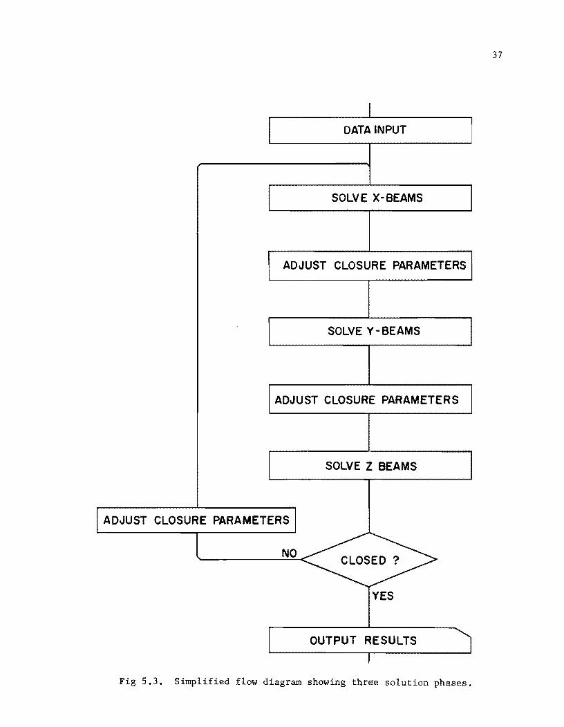
Figure 5.3 is a very simple flow diagram illustrating the general solution
process for the system. Each of the three phases of solution comprises one-
third of the iteration cycle. Closure parameters (fictitious springs) are
adjusted between each beam solution to properly reflect the effects of beams
which are temporarily held constant (the beams in the other two phases of solu-
tion).
A means of determining when this method has converged to a solution is to
have the computed deflections meet some selected degree of accuracy. The clo-
sure tests are based on deflections of each beam versus the corresponding de-
flection of beams in adjacent layers as well as tests on each successive de-
flection value of each beam from iteration to iteration.
Boundary Conditions
Boundary conditions for the grid-over-beam solution are created automati-
cally by data input to the general purpose finite-element equations. Dummy
extensions on each end of the individual beams furnish additional equations
needed to solve the system of equations. The extensions of the beams form
37
I DATA INPUT
SOLVE X-BEAMS
ADJUST CLOSURE PARAMETERS
SOLVE Y - BEAMS
ADJUST CLOSURE PARAMETERS
SOLVE Z BEAMS
I ADJUST CLOSURE PARAMETERS I
NO CLOSED?
YES
OUTPUT RESULTS 'I I
Fig 5.3. Simplified flow diagram showing three solution phases.
38
hinges which disconnect the model from any other information to right or left
of the physical beam.
Program Layer 7
Program LAYER 7 is a FORTRAN 63 language source program. It incorporates
all items previously mentioned as necessary for the solution of the simply
connected layered system. It is written especially for the CDC 1604 computer
but could be easily adapted for use on other high speed computers with a large
storage capacity.
A detailed flow chart of LAYER 7 is in Appendix 3. Pertinent notation and
a listing of the FORTRAN program are in Appendix 4. Appendix 5 contains an
input form for help in using the program. Pertinent comments and warnings are
included.
CHAPTER 6. EKAMPLE GRID-OVER-BEAM PROBLEMS
Four example problems have been selected to show the general applicability
and capability of the method of analysis presented in the preceding chapters.
Sample input and output data for the first and third examples are in Appendix 12.
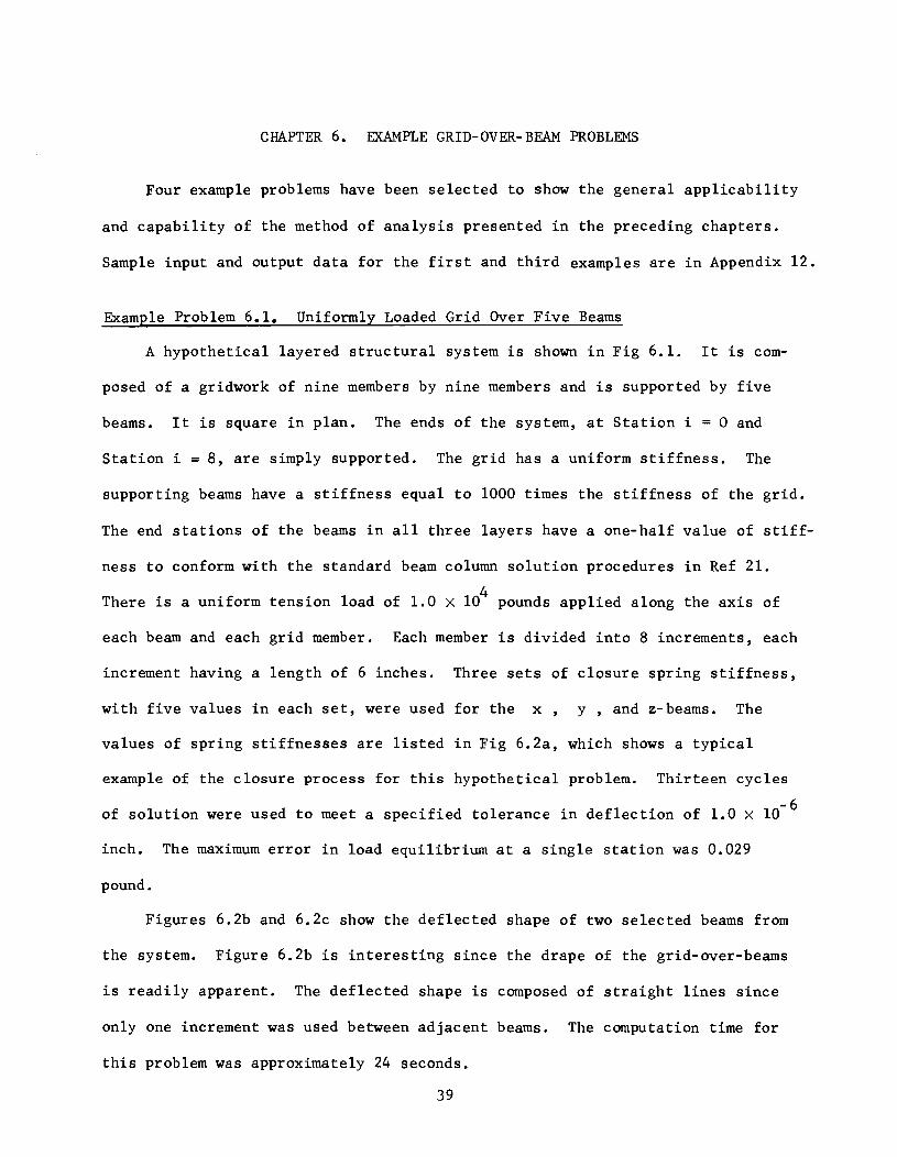
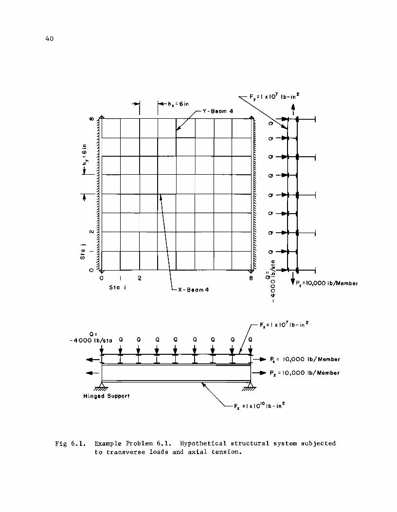
Example Problem 6.1. Uniformly Loaded Grid Over Five Beams
A hypothetical layered structural system is shown in Fig 6.1. It is com-
posed of a gridwork of nine members by nine members and is supported by five
beams. It is square in plan. The ends of the system, at Station i = 0 and
Station i = 8, are simply supported. The grid has a uniform stiffness. The
supporting beams have a stiffness equal to 1000 times the stiffness of the grid.
The end stations of the beams in all three layers have a one-half value of stiff-
ness to conform with the standard beam column solution procedures in Ref 21.
4 There is a uniform tension load of 1.0 X 10 pounds applied along the axis of
each beam and each grid member. Each member is divided into 8 increments, each
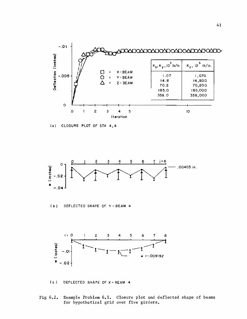
increment having a length of 6 inches. Three sets of closure spring stiffness,
with five values in each set, were used for the x y , and z-beams. The
values of spring stiffnesses are listed in Fig 6.2a, which shows a typical
example of the closure process for this hypothetical problem. Thirteen cycles
of solution were used to meet a specified tolerance in deflection of 1.0 X 10- 6
inch. The maximum error in load equilibrium at a single station was 0.029
pound.
Figures 6.2b and 6.2c show the deflected shape of two selected beams from
the system. Figure 6.2b is interesting since the drape of the grid-over-beams
is readily apparent. The deflected shape is composed of straight lines since
only one increment was used between adjacent beams. The computation time for
this problem was approximately 24 seconds.
39
40
1 •
c:::
<D
"
~
~ (\J
~
o -en
o 0 I 2
Sta i
Q= -4000Ib/sta a Q
Hinged Support
,
/ Y 8 - eam 4
V
L_ X 8eam 4
Fy= I It 107 Ib-in 2
~
t'
t'
~
~
~ ~
a
, o
o -IM-. ..... ----1
o -I~-I
c -en " ~.--II~ ...... ----1 0- I g 'Py=IO,OOO Ib/Member o ~
P" = 10,000 Ib/Member
Pz = 10,000 Ib/Member
Fig 6.1. Example Problem 6.1. Hypothetical structural system subjected to transverse loads and axial tension.
-.01
c: ~ -.005 u II .... II o
o
D 0 b,.
o 2
: X-BEAM
: Y - BEAM
= Z- BEAM
4 5
Iteration
(a) CLOSURE PLOT OF STA 4,4
3 3 KX' K Y ,10 Ib/in. Kz ' 10 Ib/in.
1.07 1,070 14.8 14,800 70.2 70,200
185.0 185,000 358.0 358,000
10
.. _0:]
-- .00403 in . 1 u c:
• -.04
( b ) DEFLECTED SHAPE OF Y - BEAM 4
i:O I 2 3 4 5 6 7 8
..... t~ , ':::;=>t
I -.olj t--t-t-t-l-t --t
'-- w =-.009192
~ -.02
( c) DEFLECTED SHAPE OF X - BEAM 4
Fig 6.2. Example Problem 6.1. Closure plot and deflected shape of beams for hypothetical grid over five girders.
41
42
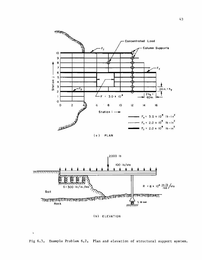
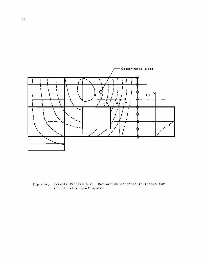
Example Problem 6.2. Support System for a Structure
Figure 6.3 depicts a more complicated structure and is similar to one
first studied by Tucker (Ref 29). The present type of analysis solved the
system as a gridwork overlying three girders. The girders are assigned a
flexural stiffness of 2 X 10⁸
lb-in2
while the x-beams in the grid are assigned
a stiffness of 3 X 10⁸
lb-in2
• This gives a total x-direction stiffness at the
girders of 5 X 10⁸
lb-in2
as compared to Tucker's total of 4 X 10⁸ lb-in2 • The
other various characteristics of the structure are outlined in Fig 6.3. Alter
nate members in the x-direction are omitted and a hole is created by omitting
portions of other beams. The soil is represented by linear springs with spring
constant S = 300 lb/in per station. The column supports are assumed embedded
in rock so that no deflection occurs at the columns. Rotational resistance is
also furnished by the columns.
Figure 6.4 shows the deflection contours for this problem. The deflec
tions are greatest in the region near the concentrated load and pass through
a zero contour at the line of column supports. A very small amount of positive
deflection occurs at the end of the longitudinal beam which carries the con-
centrated load. Results are in reasonable agreement with those of Tucker.
The deflections are slightly less than those given by Tucker due to the
increase in girder stiffness in the present problem.
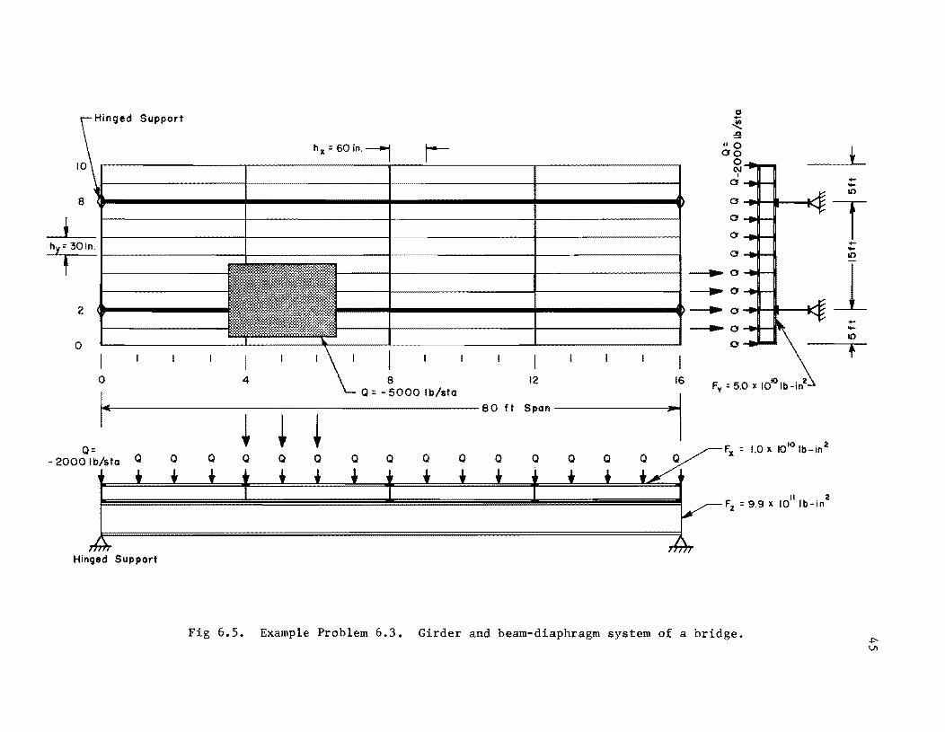
Example Problem 6.3. Girder-Diaphragm System of a Bridge
Example 6.3, shown in Fig 6.5, might represent the beam-girder-diaphragm
system of a bridge. It has 16 increments in one direction and 10 in the other.
It is supported by two large simply-supported beams. A uniform load of 2000
lb/sta acts over the whole system. An additional uniform load is shown in one
section. The load from this section was assumed as 5000 lb/sta.
Concentrated Load
Col umn Supports
9 ~--~-----+-----+----~~--~--~~-
5~--~-----+----~
~ 4 1---+---+--....... .L 2 3~----+---~~-----+~~~--~~----~~----+-__ ~--L (J) 2 Fz 24in.=h y
I 2hx = 1-' ---.j SO in. I---=-
6 8 10 12 14 IS
Station i_
Fx = 3.0 X 10⁸
I b - i n 2
Fy = 2.0 X lOB tb _in2
Fz : 2.0 X lOB Ib- in2
( a ) PLAN
2000 Ib
100 Ib/sto
(b) ELEVATION
43
Fig 6.3. Example Problem 6.2. Plan and elevation of structural support system.
44
C t t d L d r oncen ra e oa
f , 1\ I \ /' -', \ X ' 1 \ \ 1
\ 1
I 1 ,
\ \ ! \ v.: ; : ' I I \ , , \ \ .
\ \ • ;' I I I I : " \ -.8 I +.1 I \ . ~ I .
I ,
\ \ " -- /1 T I 7 If -~2 I , ~.6 / -.4
\ \ \ " ,-I I
r ,
I I .1 ,
\ \ \ " I 1/ / \. ., I
" ...... II / \ ...... - I -I -- ~
/.
" " / // / I / - ..... , ...... .,/ ", " I I
~ ....... -
Fig 6.4. Example Problem 6.2. Deflection contours in inches for structural support system.
"..
H' d S Inge upport 0 +-~ :!!
hl( =60in.~ I 10
"0
t 00 0 (\J ,
+-0 -L(')
8
t 0
T 0
0 hy= 301n. ,
.. 2
0
I I I I I I '\ I I I I I I I I I 0 4 8 12 16
= -
I Q 5000 Ib/sta
~. --~ -~ -~ --80 ft SPan----.l~1
+-
0 -L(')
----... 0 1 ---JIiIo' 0
----... 0 +-____ 0 -L(')
0 t
Q= - 2000 Ib/sta
"Ib . 2 Fz = 9.9 x 10 -In
Hinged Support
Fig 6.5. Example Problem 6.3. Girder and beam-diaphragm system of a bridge.

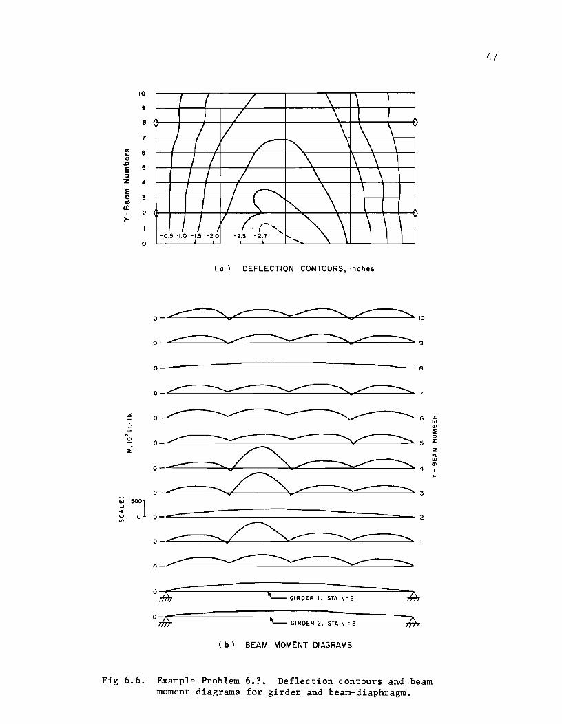
46
Deflection contours for this system are shown in Fig 6.6a. Moments
in the x-beams and girders are shown in Fig 6.6b. The moments in the girders
approach parabolic form but the magnitude is less than would be expected from
a uniformly loaded beam.
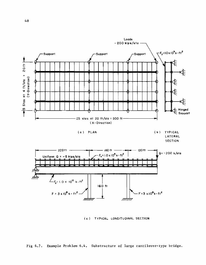
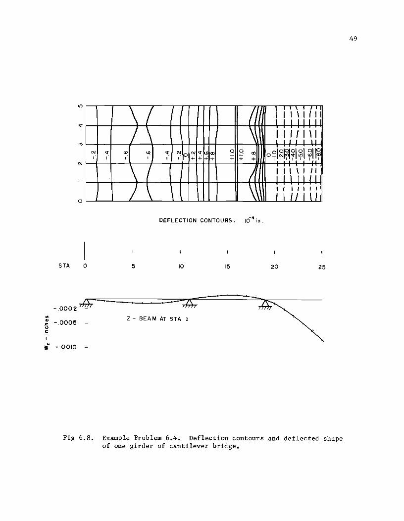
Example Problem 6.4. Cantilever Bridge Substructure
Figure 6.7 shows the structure selected for the fourth example. It
represents the beam-girder-diaphragm system of a large bridge, in this case a
cantilever-type supported by two piers. Frame action is not considered
except for the resistance to rotation furnished by the piers at the points of
connection. A dead weight of 5 kips/sta was used and concentrated loads of
200 kips/sta were placed at the cantilever end. The various characteristics
of the problem are noted in Fig 6.7. An increment length of 20 feet was used
in the x-direction while an increment length of 4 feet was used in the y-direc
tion for a total size of 500 feet by 20 feet. Two longitudinal girders were
placed under the grid system 4 feet from each edge as shown in Fig 6.7.
Deflection contours for the system and the deflected shape of one of the
beams under the system are shown in Fig 6.8. The contours show that there is
a drape of the lighter transverse members over the large girders. Positive
(upward) deflections occur between the support points while negative deflec
tions exist at all other places. The dashed lines represent contours of de
flection which did not fit regular contour spacing.
10
9
8
7
III e ... G ,g
!I E :J Z 4
E 0 :3 G III , 2 >-
( / \ / \
/ 7 \ \ \ ( r J /' ""
, \ \ / I / \ 1\ \ , / / / \ \
I / r--... \ I " '" \
/ v / ,- '" \ \ \
0 - 0.5 -1.0 -1.5 -2.0 -2.5 - 2.7 '" '\ \ 1 t .....
( a) DEFLECTION CONTOURS, inches
o
o -===~===============::::=:======--- 8
O~.~7
o r: .~ .. Q -----2
2
o ~-----..........-------.......... I
c= GIRDER I, STA y= 2
tt::::= GIRDER 2, STA y = 8
( b) BEAM MOMENT DIAGRAMS
Fig 6.6. Example Problem 6.3. Deflection contours and beam moment diagrams for girder and beam-diaphragm.
47
48
L --o C\I
" ...... c
o 0 - .-III _
'- 0 - <II - ... ...,. 0
I
- >-0--
III o -IJ)
10
f
isupport
\
(
<
t------ 220ft
Loads - 200 kips/sta
SUP=\ Support
I'
R 25 sta s at 20 ft/sta : 500 ft
( X-Direction)
(a) PLAN
160 ft --\-
Fa = 1.0 X 10⁹ k- ft2
160 ft
~J
)
v
~
( b) TYPICAL
LATERAL
SECTION
120ft ----, +0::-200 k/sta
(c) TYPICAL LONGITUDINAL SECTION
Fig 6.7. Example Problem 6.4. Substructure of large cantilever-type bridge.
N
o
STA o
-.0002 -III
~ -.000!5 -u ~
~ .. -.0010 -
N "<t: , ,
\ I I
/ \ ~ ~ "<t: (p C'! '<tjc.o <Xl Q I I , + +f+ + +
\ I )1
\ \
DEFLECTION CONTOURS,
5 10 15
z- BEAM AT STA 1
(l I ii,,/;I \ I r r I r I
j ii' I I \ I i ~~J i li
Q <Xl o sj ~irn ~I ~ I 5;1 ~ + + , I I 'iii 'i'
Ii I I \ \ i II l'l l I j 1 J
\\ I I I " " , I U 1 \I
-4 10 in.
20 25
Fig 6.8. Example Problem 6.4. Deflection contours and deflected shape of one girder of cantilever bridge.
49

!!!!!!!!!!!!!!!!!!!"#$%!&'()!*)&+',)%!'-!$-.)-.$/-'++0!1+'-2!&'()!$-!.#)!/*$($-'+3!
44!5"6!7$1*'*0!8$($.$9'.$/-!")':!
CHAPTER 7. EQUATIONS FOR THE PLATE-aVER-BEAM SYSTEM
The two primary differences between simply-connected grid-over-beam systems
and orthotropic-plate-over-beam systems are torsional and Poisson's ratio effects
which are included in the plate analysis. The supporting beams of each of the
two different types of systems are handled in exactly the same manner. An
orthotropic plate is a plate whose material and section properties may vary in
orthogonal (mutually perpendicular) directions. This chapter presents the model
used for the orthotropic-plate-over-beam system and discusses pertinent equations,
assumptions, and boundary conditions. The complete derivation of equations for
the orthotropic-plate-over-beam system is shown in Appendix 6.
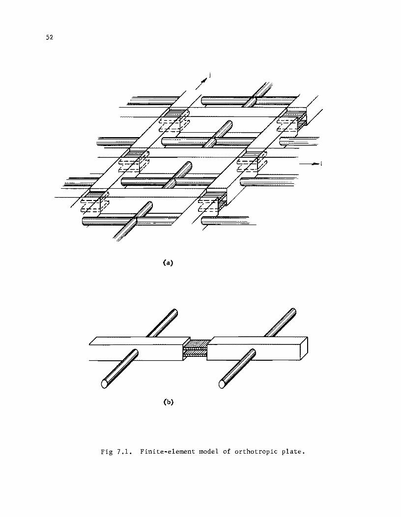
Finite-Element Model of Plate-over-Beam System
The conventional equation (Ref 28) which governs the solution of a thin
plate is
::.4W ::.4w ::.4w 0+2 0 + 0 ox4 oXZo? oy4 .9: D
(7.1)
where D is the plate bending stiffness, w is the transverse deflection, and
q is the load on the plate.
The equation which governs the solution of the beams supporting the plate,
assuming small deflection theory, is
q (7.2)
While a plate is a continuum, the finite-element model is not and it is
desirable to allow parameters to be freely discontinuous. It also is de-
sirable to include other effects such as axial tension P, rotational
51
52
(a)
(b)
Fig 7.1. Finite-element model of orthotropic plate.
53
restraints r , external torques t , and elastic spring supports s . These
effects are included in the general plate equation
nX 04W + nXY 04W + nY 04
: + ~ (rX ~:) +..Q.. (rY ~;) Ox4 0x"l0y2 oY OX oy
+~ (pX :) + ~ (pY ~;) x
otY +~ +- q - sw OX ox oy
This equation is seen to be similar to the general equation 3.5
grid-over-beam system, with the z-beam terms omitted. The term
(7.3)
for the simple
nXy 04W ox2 0y2
is the one which includes Poisson's ratio and torsion effects in the plate.
The finite-element model for the plate is shown in Fig 7.la. It is com-
posed of joints, rigid bars connecting the joints, and torsion bars between
midpoints of rigid bars. The joints are made of a material which induces
Poisson's ratio effects at the joints. Torsional stiffness of the plate is
represented by the torsion bars connecting the midpoints of each of the four
rigid bars which surround one mesh of the plate. Figure 7.lb shows one joint
of the plate with torsion bars connected to the rigid bar on each side of the
joint. The model for the beams of the plate-over-'beam system is composed of
rigid bars and spring-restrained hinges (Ref 21). The beams are not affected
by Poisson's ratio and beam torsion is neglected.
Equations 7.4 are symbolic expressions which govern the solution of the
plate-over-beam system. The first of Eqs 7.4 refers to the joints of the x-
direction of the plate, the second refers to the joints of the y-direction of
the plate, and the third refers to the joints of the supporting z-beam. The
QX, QY, and QZ terms include the previously mentioned effects of P
R , and T as well as the tOFsional stiffnesses of the torsion bars. Each
of the equations represents the complete system even though some terms are
54
different in each equation. These equations are derived from the finite-element
model. The derivations are included in Appendix 6. The arrangement of Eq 7.4
is convenient for the iterative solution process since all terms on the left
side of the equation could be considered as unknowns and all terms on the
right side could be considered temporarily as known values in the particular
phase of the iterative cycle.
QX + x KZ x + KY x Q. _ QZ _ QY + KZ Z + KYJ'. S.w. + w. = w. w. ~ ~ ~ ~ ~ ~ ~
QY + S.w~ + KX Y + KZ Y Qi _ QZ _ QX + KX x + KZ Z (7.4) w. w. = w. w.
~ ~ ~ ~ ~ ~
Z Z x Z Y Z = Q. _ QX _ QY + ~w~ + KYv/f. Q +S.w.+Kw.+Kw. ~ ~ ~ ~ ~ ~ ~
Note that Eq 7.4 is identical to Eq 3.10 which was derived previously for the
simple grid-over-beam system.
All of the the special terms have been discussed in detail elsewhere
(Ref 21). However, a brief discussion is included below as each is used in
the plate solution.
Rotational Restraint
The rotational spring r acts on the member in an angular sense and tends
to resist rotation of the member. It has typical units of in-lb/in/rad per
unit of width for the plate when shown in a distributed fashion, r. The
lumped quantity of rotational restraint R will have typical units of in-lb/rad
per unit of width.
term of Eq 7.3 is
o ( ow) oX r ax
The finite-difference version analogous to the a ox
(7.5)
55
Axial Tensions
The axial tension (or compression) may have considerable effect on the
bending of a plate. The tension P has typical units of lb per unit width
and is considered to act at the neutral axis of the member. In the present
formulation, the change in tension occurs in the joint as shown in Appendix 6,
Fig A6.l. Axial tensions are also included in the supporting beam solution.
In-plane tensions in plates may be accompanied by an in-plane shear (Ref
28). The present formulation uses principal directions only for the axial
tension since only orthogonal directions are accommodated. Thus no in-plane
shear is considered.
External Torques
An external torque is represented as a couple created by forces T./2h L
which act at stations on each side of Station i. This term is included for
cases where members frame into the system in such a manner as to apply
external moments.
Foundation Spring
The foundation spring S provides an elastic foundation response as well
as simple support capabilities. Very large S values restrain the deflection
to virtually zero. The proper ratio of Q to S may be used to produce a
specified deflection.
Assumptions of the Method
Assumptions pertinent to the use of the model in Fig 7.1 are listed
below.
(1) Only vertical connections are considered between the plate and the beams. No consideration is given to horizontal shear at the plate-beam interface.
56
(2) All layers deflect equally at cornmon joints.
(3) Deformations are small; plane sections remain plane after bending.
(4) All loads, including dead loads, act at the joints; no external forces act directly on the rigid bars.
(5) The bars between joints are rigid and weightless.
(6) Axial tensions do not produce axial deformations. In-plane shear is not considered.
(7) The joint may have the properties of an orthotropic material.
(8) The length of increment is constant on all parallel beams.
(9) All loads and stiffnesses may vary in a freely discontinuous manner.
(10) Torsion in the supporting beams is not considered.
Boundary Conditions
A variety of edge conditions may be considered for the plate-over-beam
system. The conventional edge conditions are simply-supported, free, and
elastically supported by beams. Other conditions available by use of the
present method include soil support and rotationally-restrained edges as well
as the conventional conditions. The boundary or edge conditions are created
automatically by data input to the general purpose finite-element equations
previously formulated in Chapter 3. A discussion follows concerning the con-
ventional edge conditions. The equations which follow are not used directly
in the solution process.
Simply-Supported Edge. When an edge of a plate is simply supported, the
deflection along that edge must be zero along with the bending moment at that
edge (Ref 28). Equations 7.6 state these two conditions. The simple support
condition is created by the use of a foundation spring of large numerical mag-
nitude along the edge.
57
w = 0
(7.6)
o
Free Edge. The bending moment normal to the free edge of a plate must
vanish. Along the free edge there are no twisting moments nor shearing forces.
The twisting moment and shearing force conditions can be combined to reduce the
total number of conditions at a free edge to two (Ref 28). These two
conditions are stated in Eqs 7.7 where the first is the bending moment condi-
tion and the second is the twisting moment condition.
o
(7.7)
= 0
Edge Elastically Supported by a Beam. A frequently encountered condition
in the plate-over-beam system is an edge supported elastically by a beam. In
this case, the bending moment normal to the edge must vanish and pressure from
the plate to the beam must equal the reaction in the beam (Ref 4~. These two
condi tions are
o (7.8)
The above conditions assume isotropic conditions for the plate and con-
stant stiffness for the beam.

!!!!!!!!!!!!!!!!!!!"#$%!&'()!*)&+',)%!'-!$-.)-.$/-'++0!1+'-2!&'()!$-!.#)!/*$($-'+3!
44!5"6!7$1*'*0!8$($.$9'.$/-!")':!
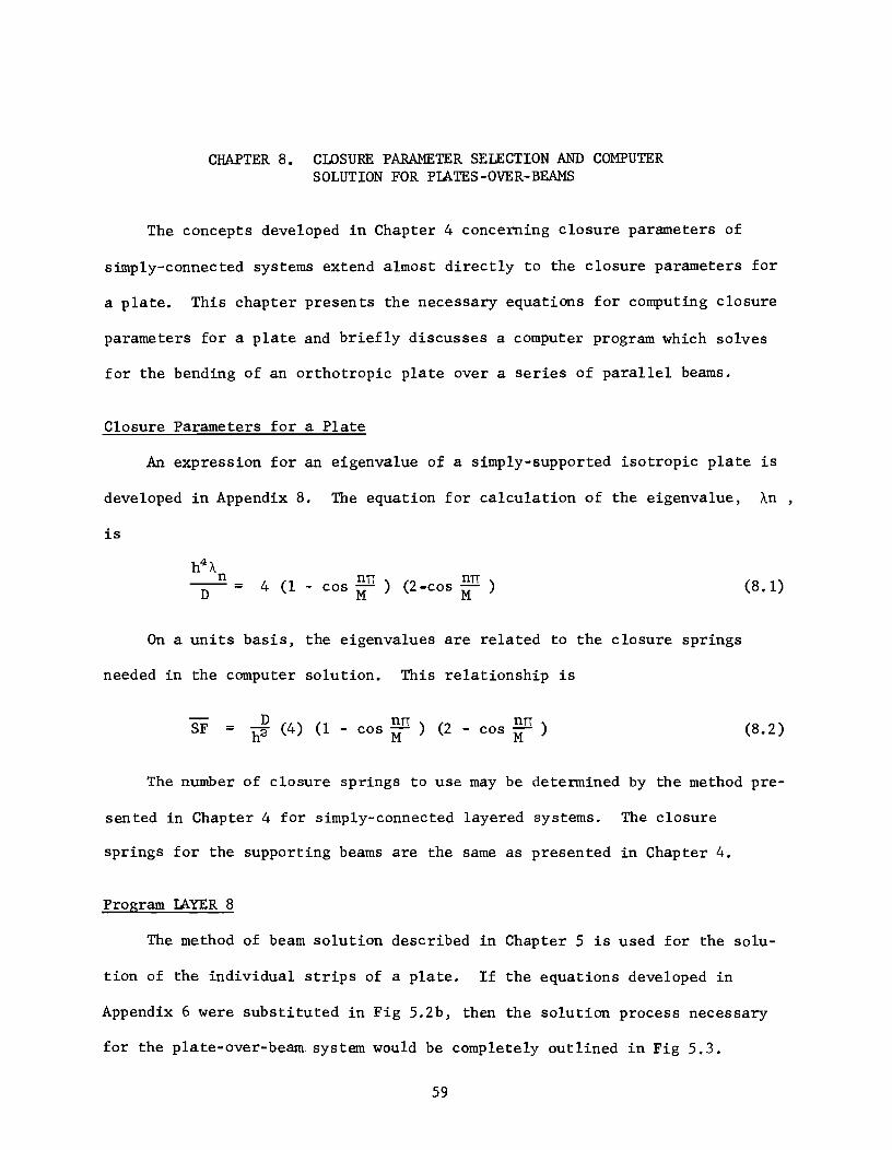
CHAPTER 8. CLOSURE PARAMETER SELECTION AND COMPUTER SOLUTION FOR PLATES-OVER-BEAMS
The concepts developed in Chapter 4 concerning closure parameters of
s~p1y-connected systems extend almost directly to the closure parameters for
a plate. This chapter presents the necessary equations for computing closure
parameters for a plate and briefly discusses a computer program which solves
for the bending of an orthotropic plate over a series of parallel beams.
Closure Parameters for a Plate
An expression for an eigenvalue of a simply-supported isotropic plate is
developed in Appendix 8. The equation for calculation of the eigenvalue, An,
is
D 4 (1 - cos ~n ) (2-cos ~n ) (8.1)
On a units basis, the eigenvalues are related to the closure springs
needed in the computer solution. This relationship is
SF = D nn nn h2 (4) (1 - cos M: ) (2 - cos M: ) (8.2)
The number of closure springs to use may be determined by the method pre-
sen ted in Chapter 4 for simply-connected layered systems. The closure
springs for the supporting beams are the same as presented in Chapter 4.
Program LAYER 8
The method of beam solution described in Chapter 5 is used for the solu-
tion of the individual strips of a plate. If the equations developed in
Appendix 6 were substituted in Fig 5.2b, then the solution process necessary
for the p1ate-over-beam. system would be completely outlined in Fig 5.3.
59

60
Program LAYER 8 is written in FORTRAN 63 language for the CDC 1604
or CDC 6600 digital computers. A detailed flow diagram of this computer pro
gram is in Appendix 9.
Notation for Program LAYER 8 is in Appendix 10 with a complete listing of
the source program. Compilation time for this FORTRAN program is approxi
mately 2 minutes. The maximum number of strips into which the plate may be
divided is 25 by 25. Several variables have double meanings as shown in the
Notation listing. This is only to aid in the printout of all necessary
results. An input form is in Appendix 10 along with additional comments about
the program and warnings to the user.
CHAPTER 9. EXAMPLE PLATE- OVER-BEAM PROBLEMS
Four example problems follow which indicate the capabilities of the
method of analysis for plate and plate-aver-beam problems. Two of the prob-
lems selected are compared to theoretical solutions given by Timoshenko and
Woinowsky-Krieger (Ref 28). Sample input for all 4 examples and output data
for the second and fourth examples are in Appendix 13.
Example Problem 9.1. Isotropic Plate with Concentrated Load
A simple isotropic plate with Poisson's ratio of 0.25 is shown in Fig 9.1.
The plate is 48 inches square and 0.98 inches thick, with simply-supported
5 boundaries and has one concentrated load of 10 pounds at the center. There is
a constant bending stiffness throughout. The plate is divided into sixteen 3-
inch strips in the x-direction and eight 6-inch strips in the y-direction. No
supporting beams are used. The simple supports are created by specifying very
stiff foundation springs in the input data. The modulus of elasticity is
3.0 X 10⁷ lbs/in2
•
Figure 9.2 shows deflection contours resulting from this problem. The de-
flection at the midpoint of the plate is 1.11 inches which is in very close
agreement with 1.07 inches given by the closed-form solution of Timoshenko and
Woinowsky-Krieger. Comparison of the corner uplift forces is accomplished by
taking the product of the foundation spring stiffness S and the corner de-
flection w. 4
The computed results show a value of 1.28 X 10 pounds versus
4 1.219 X 10 pounds from Timoshenko and Woinowsky-Krieger.
Example Problem 9.2. End-Supported Plate with Two Edge Beams
The second example is shown in Fig 9.3. It is a plate 10 feet square and
2.02 inches thick, simply supported along two edges and supported along the
61
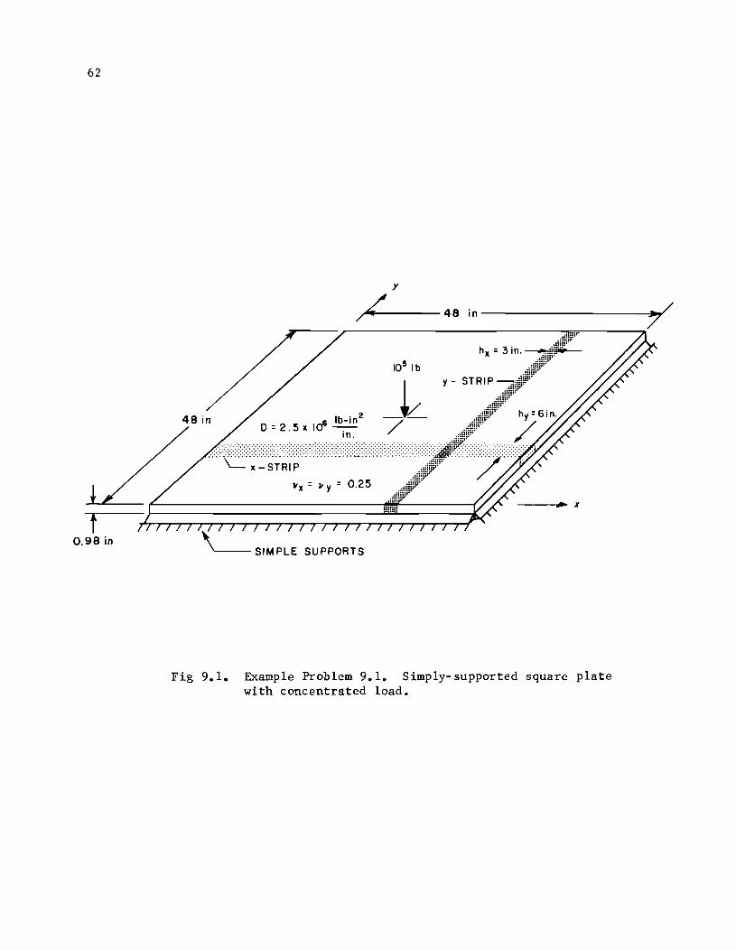
62
0.98 in
y
/"AL ...... ---- 48 in ------------,.,..
6 Ib-in2 0= 2.5 x 10 -.
In .
105 Ib
_L /
.. :.:.:.:.:.;:;:;:;:::;:;:;:;:;:;:::::::;:::::;:::::::::;:;:;:;:;:::;:::::::::;:::;::.:.:.:.:.:.:-:.:.:-:.:.:.:::::.:.:-:.' ··:·:·:·:c:·:~·:~:·~;~~·~·:·:·:·:·:-:·:·:·;.;,:·:·:·:·;::.::,;.:::::.;.:.;.; ....................... .
II X =lIy=0.25
,'---- SIMPLE SUPPORTS
Fig 9.1. Example Problem 9.1. Simply-supported square plate with concentrated load.
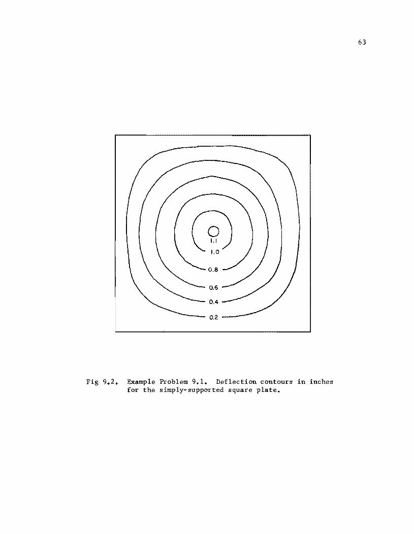
~ 1.0
0.2
Fig 9.2. Example Problem 9.1. Deflection contours in inches for the simply-supported square plate.
63
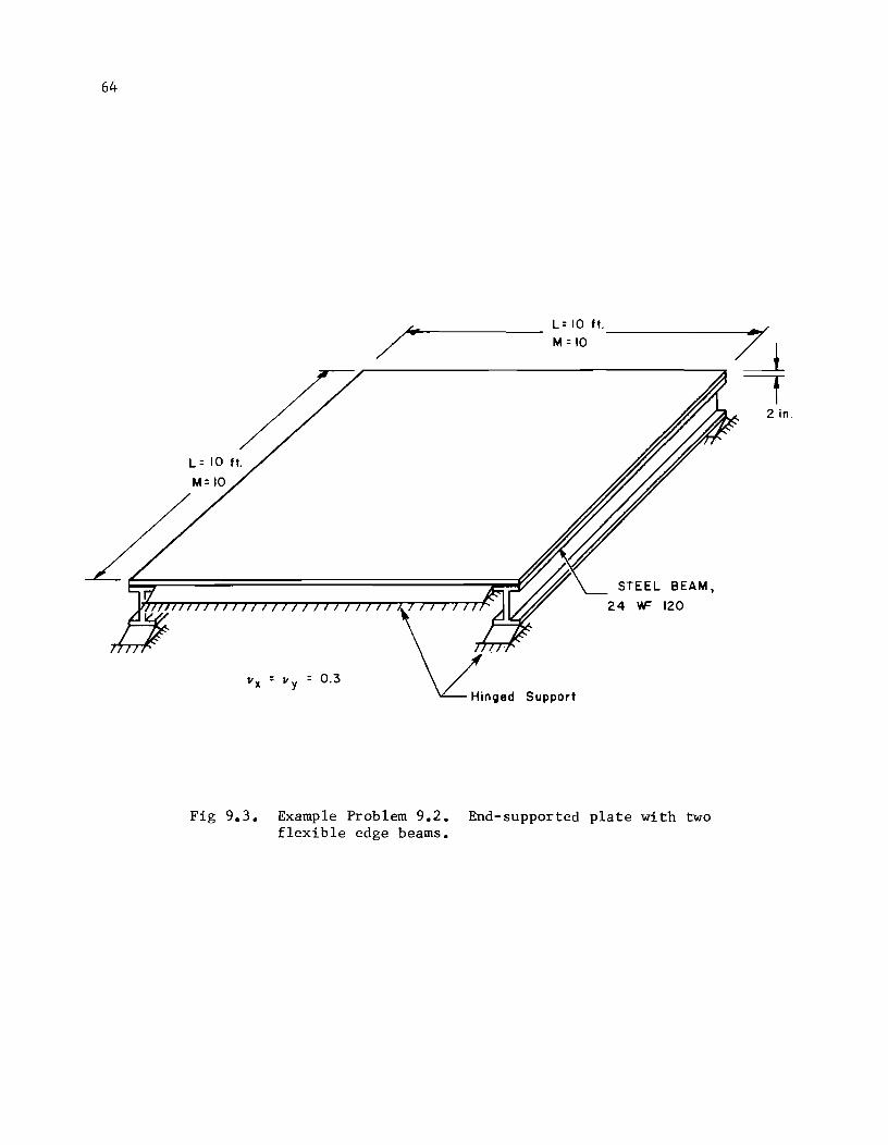
64
vx = v y = 0.3
L= 10 ft. --7//1 M = 10 -------.l.
Hinged Support
STEEL BEAM,
24 'IF 120
2 in.
Fig 9.3. Example Problem 9.2. End-supported plate with two flexible edge beams.
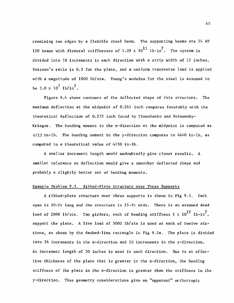
65
remaining two edges by a flexible steel beam. The supporting beams are 24 WF
120 beams with flexural stiffnesses of 1.09 X 10¹¹ 1b-in2 . The system is
divided into 10 increments in each direction with a strip width of 12 inches.
Poisson's ratio is 0.3 for the plate, and a uniform transverse load is applied
with a magnitude of 1000 1b/sta. Young's modulus for the steel is assumed to
be 3.0 X 10⁷ 1b/in2
.
Figure 9.4 shows contours of the deflected shape of this structure. The
maximum deflection at the midpoint of 0.265 inch compares favorably with the
theoretical deflection of 0.272 inch found by Timoshenko and Woinowsky
Krieger. The bending moment in the x-direction at the midpoint is computed as
4713 in-lb. The bending moment in the y-direction computes to 4640 in-1b, as
compared to a theoretical value of 4730 in-lb.
A smaller increment length would undoubtedly give closer results, A
smaller tolerance on deflection would give a smoother deflected shape and
probably a slightly better set of bending moments.
Example Problem 9.3. Ribbed-Plate Structure over Three Supports
A ribbed-plate structure over three supports is shown in Fig 9.5, Each
span is 20-ft long and the structure is 25-ft wide. There is an assumed dead
load of 2000 1b/sta. Two girders, each of bending stiffness 1 X 10¹²
1b-in2
,
support the plate. A live load of 5000 1b/sta is used at each of twelve sta
tions, as shown by the dashed-line rectangle in Fig 9.5a. The plate is divided
into 16 increments in the x-direction and 10 increments in the y-direction.
An increment length of 30 inches is used in each direction. Due to an effec
tive thickness of the plate that is greater in the x-direction, the bending
stiffness of the plate in the x-direction is greater than the stiffness in the
y-direction. Thus geometry considerations give an "apparent" orthotropic
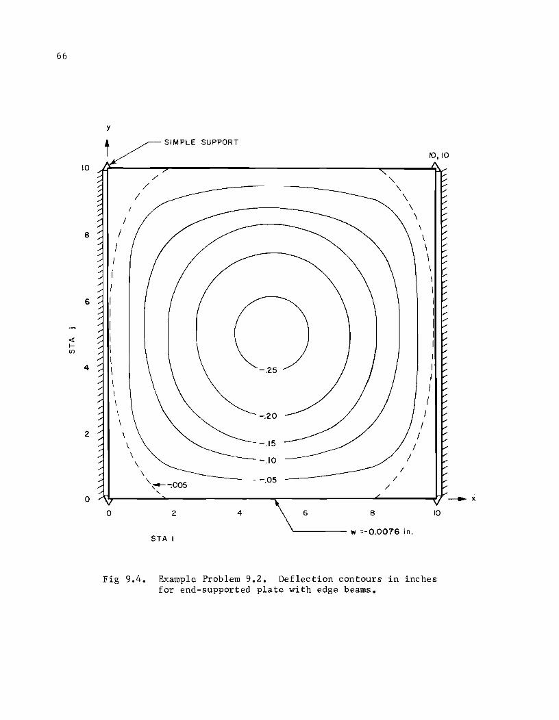
66
10
8
6
<[ f-en
4
2
0
y
SUPPORT t~SIMPLE 10,10
/ "-/ \ / \
/ \
/ \
/ \
\ I \ I
, I \
\
\
I I I I I I
--.25 I I I
\ I \ -.20 \
\ -.15
\ -.10 \
\ /
\'~-:005 -.05 / /
'-
0 2 4 6 8 10
w =-0.0076 in. STA i
Fig 9.4. Example Problem 9.2. Deflection contours in inches for end-supported plate with edge beams.
---. x
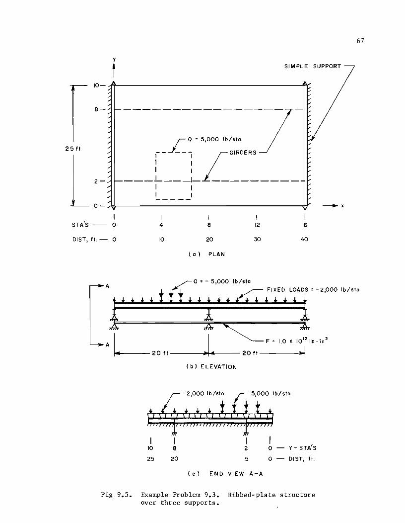
67
y
f SIMPLE SUPPORT
10-~----------------------------------------------~~
8-
25ft
2-
r a = 5,000 Ib/sto
__ J___ LGIRDERS I I
1 I I I
_____ I ____ 1__ __ __________ __
1 I I
O-~._--------------------------------------------_dr
STA'S -- 0 4 8 12 16
DIST, ft. -- 0 10 20 30 40
( 0) PLAN
Ib/sto A
FIXED LOADS = -2,000 Ib/sto
L IF = 1.0 J( 1012 1b _ in 2
A 20 f t --------~» ..... &r---- 2 0 ft .. I
10
25
I 8
20
(b) ELEVATION
-2,000 Ib/sto
2
5
(c) END VIEW A-A
o o
Y - STA'S
DIST, ft.
Fig 9.5. Example Problem 9.3. Ribbed-plate structure over three supports.
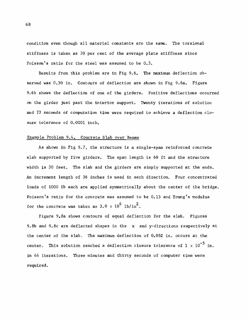
68
condition even though all material constants are the same. The torsional
stiffness is taken as 70 per cent of the average plate stiffness since
Poisson's ratio for the steel was assumed to be 0.3.
Results from this problem are in Fig 9.6. The maximum deflection ob
served was 0.30 in. Contours of deflection are shown in Fig 9.6a. Figure
9.6b shows the deflection of one of the girders. Positive deflections occurred
on the girder just past the interior support. Twenty iterations of solution
and 73 seconds of computation time were required to achieve a deflection clo-
sure tolerance of 0.0001 inch.
Example Problem 9.4. Concrete Slab over Beams
As shown in Fig 9.7, the structure is a single-span reinforced concrete
slab supported by five girders. The span length is 60 ft and the structure
width is 30 feet. The slab and the girders are simply supported at the ends.
An increment length of 36 inches is used in each direction. Four concentrated
loads of 1000 lb each are applied symmetrically about the center of the bridge.
Poisson's ratio for the concrete was assumed to be 0.15 and Young's modulus
for the concrete was taken as 3.0 X 10⁶ lb/in2 •
Figure 9.8a shows contours of equal deflection for the slab. Figures
9.8b and 9.8c are deflected shapes in the x and y-directions respectively at
the center of the slab. The maximum deflection of 0.052 in. occurs at the
center. This solution reached a deflection closure tolerance of 1 X 10⁻⁵ in.
in 44 iterations. Three minutes and thirty seconds of computer time were
required.
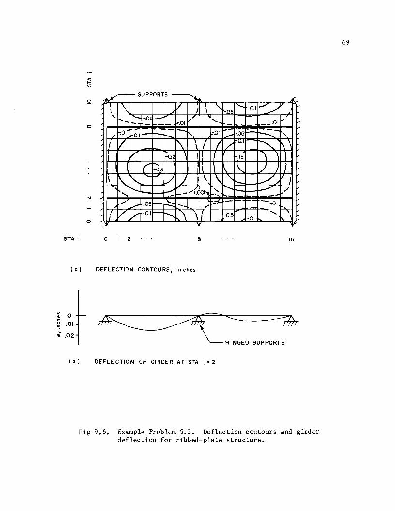
P RT o
~SUPO S 't\ ,. I \ v I "- I ......... ~O.I .-/ V ~ ,.. \ ./ I \ -;05 - / " ,. ' ..... - ~ -;Ol: ,- ~/ ' .. V' -. 1--- f=".01 - .... - .- -:01 ,..
~- - - - -... 1-'"- - - ~- "" ,. /
-:01 -0.1 r-....... " ~·.Ol ./ -.05 -...... "
~ ,..
V '\ \ f I -0.1 1--j--... l\\ ~
'" I / J.-
" J.-: : V I"- , H '\ ,
-02 -.15 J.-,.. I ( (" :Q3 \ \. /
J.-,.. \ J.-
CD
,..
\. ~ ~ '--' L/ \ \ "- / II J L , ....... ,....,. ./ J.-,..
-'r- . i"--. ./ ""(001--. "- .......... - ,,/ i-' '" " --- r-- ~.
_ .... J.-
"" ~ ~ - -- -- - i-' ",. -:05 - -:01 '" ",.- -. ". i-'
'" ~
1/ V V -0.1 r-- ........... ,",\ '\ ( .... "' '\ '" -:05 , -0.1 ~ ,
N
o ,
STA o 2 8 16
(Q) DEFLECTION CONTOURS, inches
:: 0 ~
g .01 .. ~ .02
~-= ---;A ~'NGED SUPPORTS
(b ) DEFLECTION OF GI RDER AT STA j: 2
Fig 9.6. Example Problem 9.3. Deflection contours and girder deflection for ribbed-plate structure.
69
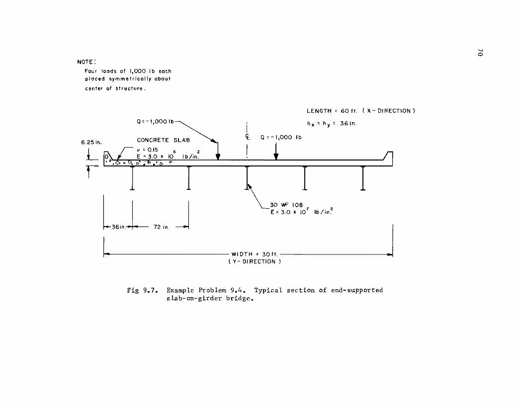
NOTE:
Four loads of 1,000 Ib each pi aced sym met ric ally abou t
center of structure.
6.25;n.
L 1
6 2 10 Ib/in.
l36;"L 72;" J
. I It.
I
LENGTH:: 60 ft. (X DIRECTION)
hx:: hy: 36in .
Q:: 1,000 Ib
30 VF 108 E:: 3.0 X 10
1 Ib/in~
1""'----------------WIDTH: 30 ft. -------------......,j ( y- 01 RECTION )
Fig 9.7. Example Problem 9.4. Typical section of end-supported slab-on-girder bridge.
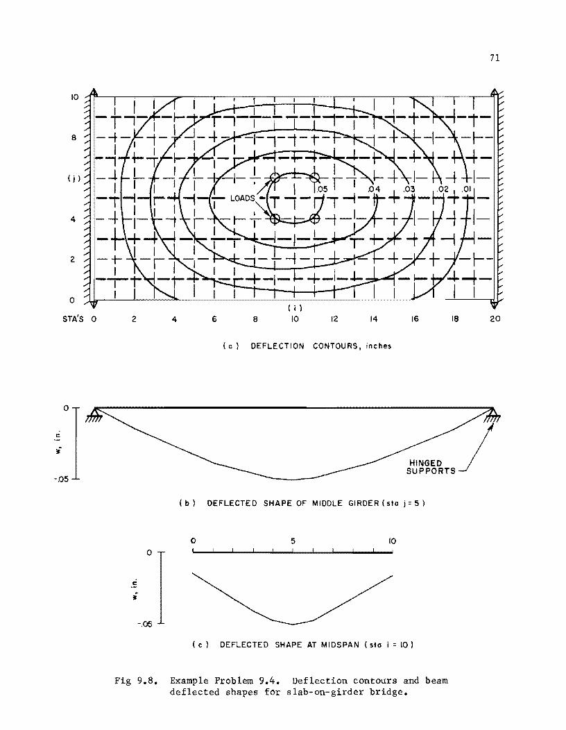
a
(j)
4
2
a
STA'S a
a
c
i
-.05
2 4 6 a 12 14 16
(a) DEFLECTION CONTOURS, inches
( b) DEFLECTE D SHAPE OF MIDDLE GIRDER (sto i = 5 )
o 5 10
a
c
-.05
( c) DEFLECTED SHAPE AT MIDSPAN (sto i = 10)
Fig 9.8. Example Problem 9.4. Deflection contours and beam deflected shapes for slab-on-girder bridge.
71
18 20

!!!!!!!!!!!!!!!!!!!"#$%!&'()!*)&+',)%!'-!$-.)-.$/-'++0!1+'-2!&'()!$-!.#)!/*$($-'+3!
44!5"6!7$1*'*0!8$($.$9'.$/-!")':!
CHAPTER 10. CONCLUSIONS AND RECOMMENDATIONS
A method of analysis for the bending of structural systems composed of
layers of grids or plates over parallel beams has been presented. The numeri-
cal procedure has been shown to be rapid and accurate. It has been applied to
both simple and complex problems and favorably compared to theoretical solu-
tions. A method for the selection of closure parameters for the a1ternating-
direction iterative solution has also been presented.
The following conclusions have been reached.
(1) The method of analysis is applicable to a wide variety of problems of complex geometry, loading, stiffness, and support conditions. Orthotropic as well as isotropic plate stiffnesses are allowable in the p1ate-over-beam solution.
(2) The method is accurate. Problems were compared to theoretical answers with close agreement.
(3) The method for selection of the proper range of closure parameters gives adequate results. The optimum number of parameters to use is open to question. The result, if poor selections are made, is that the time to solve the problem will increase.
(4) The concept of closure parameters being based on the opposing or replaced beams is applicable for systems of the type studied. The method presented predicts the same closure parameters for each beam of the system when uniform geometry and stiffness exist. Different values of parameters are predicted when geometry and stiffness conditions are allowed to vary.
(5) The method presented for the solution of the layered structural system also is directly applicable to the cases of simple grids, isotropic plates or orthotropic plates without supporting beams.
The method which has been described furnishes a much more general means
of analyzing certain structural problems than has been previously available.
It is envisioned that some extension to the method might be desirable in
73

74
order to consider an even wider class of problems than those presented. The
following comments are deemed pertinent to extensions and further uses of this
method.
(1) The in-plane or axial tensions acting on such systems need additional study. Hondros and Marsh (Ref 13) point out that the neutral planes of girders do not stay coplanar or stationary and that distributed inplane forces will be induced due to bending. The present program does not allow a varying neutral surface, but the mechanics of induced in-plane forces could be handled readily. In-plane shear will need to be included in the solution when directions other than principal directions are considered.
(2) A natural closure parameter selection process, such as the one described briefly, offers the possibility of an extremely efficient and straightforward closure mechanism for the alternating-direction techniques. A detailed study of such a closure selection process is recommended.
(3) Extensions of the method to handle non-orthogonal beams and to solve more than three layers of beams may be desirable. The non-orthogonal support system appears to be necessary for certain classes of structures, such as on-off ramps for freeways. A maximum of five layers is envisioned for anyone problem that could consist of a plate and a grid over a set of beams.
(4) Horizontal shear at the plate-beam or grid-beam interface should be studied as it pertains to full composite action of the structure. There appear to be ways of approximating this effect, such as using an increased but equivalent stiffness in the beams or by use of iterative solutions which adjust axial tension and induced couples to achieve compatibility.
REFERENCES
1. Ang, Alfredo H. S., and Nathan Newmark, "A Numerical Procedure for the Analysis of Continuous Plates," Proceedings, Second Conference on Electronic Computation, Structural Division, ASCE, Pittsburg, Sept., 1960.
2. Ang, Alfredo H. S., and Wallace Prescott, "Equations for Plate-Beam Systems in Transverse Bending," Journal of the Engineering Mechanics Division, Proceedings, ASCE, Dec., 1961.
3. Chen, T. Y., C. P. Siess, and N. W. Newmark, 'Noments in Simply Supported Skew I-Beam Bridges," University of Illinois Engineering Exp. Sta. Bull., No. 439, 1957.
4. Chu, Kuang-Han, and G. Krishnamoorthy, "Use of Orthotropic Plate Theory in Bridge Design," Journal of the Structural Division, Proceedings, ASCE, ST 3, June, 1962, pp 35-78.
5. Clifton, Rodney J.,Jerry C. L. Chang, and Tung Au, "Analysis of Orthotropic Plate Bridges," Journal of the Structural Division, Proceedings, ASCE, ST 5, Oct., 1963, pp 133-172.
6. Conte, S. D., and R. T. Dames, "An Alternating Direction Method for Solving the Biharmonic Equation," Mathematical Tables and Other Aids to Computation, Vol. 12, No. 63, July, 1958.
7. Crandall, Stephen H., and Norman C. Dahl, ed., An Introduction to the Mechanics of Solids, McGraw-Hill Book Co., Inc., New York: 1959.
8. Dow, Harris F., Charles Libove, and Ralph E. Hubka, "Formulas for the Elastic Constants of Plates with Integral Waffle-like Stiffening," National Advisory Committee for Aeronautics, Report 1195, 1954.
9. Fung, Y. C., "Bending of Thin Elastic Plates of Variable Thickness," Journal of the Aero. Sciences, Vol. 20, No.7, July, 1953, pp 455-468.
10. Haliburton, T. Allan, "A Numerical Method of Nonlinear Beam-Coltunn Solutian~" Thesis, The University of Texas, Austin, June, 1963.
11. Haliburton, T. Allan, Unpublished notes for CE397.6, Seminar on Soil Mechanics, The University of Texas, Spring, 1965.
12. Hearmon, R. F. S., An Introduction to Applied Anisotropic Elasticity. Oxford University Press, 1961.
13. Hondros, G., and J. G. Marsh, "Load Distribution in Composite Girder-Slab Systems," Journal of the Structural Division, Proceedings, ASCE, ST 11, Nov., 1960, pp 79-109.
75
76
14. Hoppmann, W. H., "Bending of Orthogonally Stiffened Plates,1I Journal of Applied Mech., Transactions, ASME, Vol. 77, 1955.
15. Hoppmann, W. H., 2nd, N. J. Huffington, Jr., and L. S. Magness, I~ Study of Orthogonally Stiff!ened Plates," Journal of Applied Mech., Sept., 1956.
16. Huffington, N. J., Jr., "Theoretical Determination of Rigidity Properties of Orthogonally Stiffened Plates," Journal of Applied Mech. , March, 1956.
17. Ingram, Wayne B., IISolution of Generalized Beam-Colunms on Non-Linear Foundations,1I Thesis, The University of Texas, Austin, Aug., 1962.
18. Jensen, V. P., "Analysis of Skew Slabs,1I University of Illinois Engineering Exp. Sta. Bull., No. 332, 1941.
19. Marcus, H., IIBending of Orthogonally Stiffened Plates," Journal of Applied Mech., Dec., 1955.
20. Matlock, Hudson, '~pplications of Numerical Methods to Some Problems in Offshore Operations," Proceedings, First Conference on Drilling and Rock Mechanics, The University of Texas, Austin, Texas, Jan. 23-24, 1963.
21. Matlock, Hudson, and T. Allan Haliburton, "A Finite-Element Method of Solution for Linearly Elastic Beam-Columns," Research Report No. 56-I, Center for Highway Research, The University of Texas, Austin, Sept., 1966.
22. Matlock, Hudson, and T. Allan Haliburton, "Inelastic Bending and Buckling of Piles," A paper presented at the Conference on Deep Foundations, Mexican Society of Soil Mech., Mexico City, Dec., 1964.
23. Matlock, Hudson, and Wayne B. Ingram, "Bending and Buckling of SoilSupported Structural Elements," Paper No. 32, Proceedings, Second Pan-American. Conference on Soil Mechanics and Foundation Engineering, Brazil, June, 1963.
24. Matlock, Hudson, and Richard Lee Tucker, "Alternating-Direction Relaxation of Finite-Element Grid-Beam Systems," Unpublished Report, The University of Texas, Austin,
25. Peaceman, D. W., and H. H. Rachford, Jr., "The Numerical Solution of Parabolic and Elliptic Differential Equations, II Journal of Soc. Indust. Appl. Math., Vol. 3, No.1, March, 1955, pp 28-41.
26. Salani, Harold J., Unpublished notes for CE 397.6, Seminar on Soil Mechanics, The University of Texas, Austin, Spring, 1965.
27. Schade, H. A., "The Orthogonally Stiffened Plate under Uniform Lateral Load," Transactions, ASME, Vol. 62, 1950.
28. Timoshenko, S., and S. Woinowsky-Krieger, Theory of Plates and Shells. McGraw-Hill Book Co., Inc., New York: 1959.
29. Tucker, Richard Lee, "A General Method for Solving Grid-Beam and Plate Problems," Ph.D. dissertation, The University of Texas, Austin, June, 1963.
30. Vitols, Vilis, Rodney J. Clifton, and Tung Au, "Analysis of Composite Beam Bridges by Orthotropic Plate Theory," Journal of the Structural Division, Proceedings, ASCE, ST 4, Aug., 1963, pp 71-94.
31. Wachspress, E. L., "Optimum Alternating-Direction-Implicit Iteration Parameters for a Model Problem," J. Soc, Ind. Appl. Math., 10, pp 339-50.
77
32. Young, David M., Jr., and Mary F. Wheeler, "Alternating Direction Methods for Solving Partial Difference Equations," TNN-30, The University of Texas Computation Center, Austin, De., 1963.
33. Young, David M., Jr., Mary F. Wheeler, and James A. Downing, "On the Use of the Modified Successive Overrelaxation Method with Several Relaxation Factors," TNN-39, The University of Texas Computation Center, Austin, Jan., 1965.

!!!!!!!!!!!!!!!!!!!"#$%!&'()!*)&+',)%!'-!$-.)-.$/-'++0!1+'-2!&'()!$-!.#)!/*$($-'+3!
44!5"6!7$1*'*0!8$($.$9'.$/-!")':!
APPENDIX 1
DERIVATION OF EQUATIONS FOR A SIMPLE GRID OVER PARALLEL BEAMS

!!!!!!!!!!!!!!!!!!!"#$%!&'()!*)&+',)%!'-!$-.)-.$/-'++0!1+'-2!&'()!$-!.#)!/*$($-'+3!
44!5"6!7$1*'*0!8$($.$9'.$/-!")':!
APPENDIX 1. DERIVATION OF EQUATIONS FOR A SIMPLE GRID OVER PARALLEL BEAMS
Equations 3.10 were presented in Chapter 3 as the governing equations for
the layered system. These equations involve the assumption that the loads Q
and the springs S act on all beams of the system. The fictitious springs or
closure parameters are temporary representations of the x
y and z-beams respectively and serve to add stability as well as rapid
closure to the system. Likewise, the rotational restraints RX
and the external torques and the axial forces Py d , an
pZ act on the individual beams.
Consider Fig Al.l which represents a free-body of a section of an x-beam
with the y and z-beams assumed temporarily constant and represented by the
terms y Q. . , ~,J
z Q. . , ~,J
All forces pertinent to the behavior of
the system are shown. The external torques T and the rotational restraints
R , both of which are considered to act over a distance of two increment
lengths, have been reduced to their force counterparts which act at some ith
th joint of the j beam. The rigid bars are assumed to have no external forces
applied. Thus, the axial tensions P and the shear V will change at the ith
joint. A complete derivation of the equations governing the behavior of this
layered system follows.
Considering only the one joint of an x-beam shown in Fig Al.l and summing
forces in the vertical direction results in Eq Al.l.
Q .. - S.w~ . - Q~ . - Q: . + ~ . - ~+l . - KY(w~ . - w~ .) ~,J ~ ~,J ~,J ~,J ~,J ~ ,J ~,J ~,J
z x z - K (w .. - w .. ) +
~,] ~,]
x T. 1 . ~- ,] 2h
x o
x x R'+l . 9'+1 . ~ .1 ~ ,1_
2h x
81
x x R. 1 . 9. 1 . ~-,] ~- .1
2h x
x T. 1 . + ~+, 1
2h x
(Al.l)
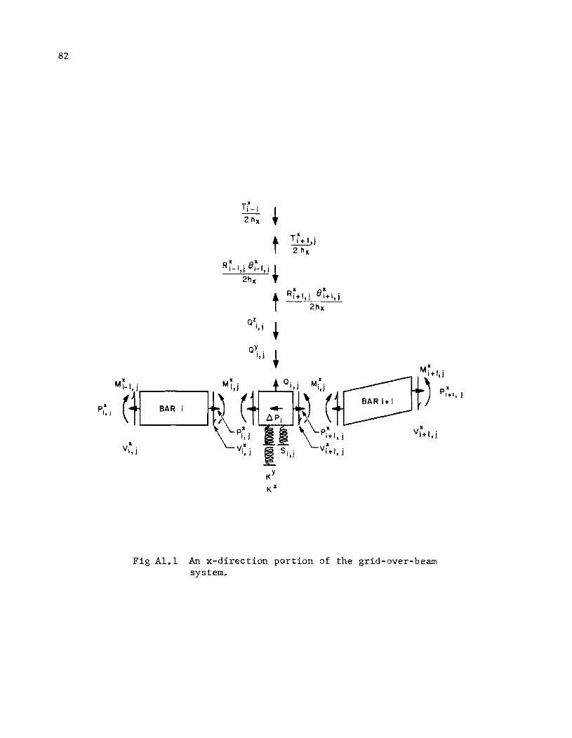
82
II PI,I
II
M(~ BAR
v·· I,!
2 hx t t
II ell Ri-I,i i-I,i I
2hx ,
T i + I,j 2 hx
II ell • Ri+I,i i+I,i I 2hx
t t
s· . I,)
Fig Al.l An x-direction portion of the grid-aver-beam system.
83
The shear ~. can be obtained by summing moments about the left end of 1,]
Bar i in Fig AI.I, i.e.,
~ I . + ~ . h + p~ . (- w~ I j + w~ j) - ~. = 0 1-,J 1,J x 1,J 1- , 1, 1,J
and solving for the shear ~ , 1,]
= hI [- ~ 1 ' + ~ . - p~ , (- w~ 1 ' + w~ ,)] x 1-,] 1,] 1,J 1-,] 1,]
(A1.2)
(Al.3)
A similar expression for the shear ~+l ' 1 ,] may be obtained by summing
moments about the right end of Bar i+l in Fig Al.l, i.e.
and
~+l,j = ~ [- M~,j + ~+l.j - ~+l,j (- W~,j + W~+l.j) J x
Substituting Eqs Al.3 and Al.4 into Al.l shows that
x x x x x x p, . (- w, 1 . + w . .) + P'+l . (- w, j + w1'+1,J.) 1,J 1-,J 1,J 1,J 1,
x x x x x R'+1 . 9'+1' R, 1 ' 9, l' T·+1 · + ~ "2 ~ .1 - ~- "2 ~- ., + ~ 2,J
Central difference expression for the slopes
x e'+l ' 1 ,J
x e, 1 ' 1- ,]
::::
=
x x -Wi ,i+ wi+2.j
2h x
x x -w· 2 ·+w ..
1-.1 1,J 2h
x
and
:::: 0
x e, I ' 1- ,J
(AI.4)
(AI.S)
are
(Al.6)
(Al.7)
It remains only to express the moments M in terms of deflections. For small
deflection theory, the conventional approximation relating beam curvature to
84
bending moment is
= M F
where F is the flexural stiffness EI (product of cross-sectional
moment of inertia and Young's modulus).
(Al.8)
Equation Al.8 written in second-order central difference form in the x-
direction about Joint i,j gives the relation
x x x (w, 1 ' - 2w, +w'+l')
~j = FX 1.- 2] 1. I j 1. d 1., 1.,j h2
x (A1.9)
and in the y and z-direction respectively
(w~ , 1 - 2w~ + w~ '+1) MY FY 1. 2 ] - 1. 2 j 1. Z J
1.,j 1.,j h2 Y
(Al.lO)
and
z z z (w, 1 . - 2w, + w'+l ,)
~ = F~ 1.- d 1. 2 j 1. d 1.,j 1.,j h2
z (A1.ll)
Writing Eq Al.9 at three adjacent stations and substituting these and the
expressions for slopes given by Eqs Al.6 and Al.7 into Eq Al.S yields
h I Q ' . - Q~ , - Q~ . x ~ 1.,J 1.,J 1.,J x
- S, ,w, , 1.,J 1.,J
y( x _ y ) K w,' w,. 1.,J 1.,J
x (w, 1 .
X 1.- 2 J - 2F. , 1.,J
x + F '+1 ' 1. , J
x (w, .
1.zl
x (w. 2 ' X 1.- .,
F, 1 . 1. - , J
x - 2w. .
1. 2 J
x - 2w i +1 .
1 J
x + W'+2 .) 1. zl
x x - 2w, 1 ' + w, .)
1.- zJ 1.d h2
x
(Equation Cont'd.)
85
x (-
x x x (-
x + w~+l .) + P. w. 1 . + w .. ) - P'+l . w. 1,j 1- , J 1,] 1 , J 1,j 1 ,J
x x x x (-x x
R. 1 . (-w. 2 . + w .. ) R. 1 . w. + w'+2 .) + 1- z] 1- z] 1 Z ] 1+ z] 1 Z j 1 "
2 2h 2 2h x x
x x T. 1 . T. 1 . 1+ z] + 1- I J (A1.l2)
2 2
Multiplying by and rearranging terms results in
x w. 2 .
1- ,] [F~ 1 . 1- , J
h
4x (R~ 1 .)J + w~ 1 . [- 2F~ 1 . - 2F~ . - h2 P~ .J 1- ,J 1- ,J 1- ,J 1,J x 1,J
+ W~ . [F~ 1 . + 4F~ . + F~+l . + h2 (P~ . + P~+l .) 1,J 1-,J 1,J 1,J x 1,J 1,J
+ \{ (RX + RX ) + S h3 + h3
X (KY + KZ)]
4 . l' '+1' .. 1-,J 1,J 1,J x
x + Wi+l,j
x + W'+2 . 1 ,J
1 2h
x
which is of the form
[- 2F~ . 1,J
[F~+l,j
x _ h2 P~+l, jJ - 2F'+1 . 1 , J x
h x x ] - 4"" Ri +1,j
Equation Al.13 is of exactly the same form as Eqs 3.10 except that
(Al.13)
(A1.l4)
x Q .. 1,]
is now expanded in a more useable form. All terms on the left side of Eq
Al.13, excepting the S , KZ , and KY terms, represent The
forms of Y Q .. 1,J
and Z Q •• 1,J
remain to be developed.
A similar derivation for the y-beam layer would show that
86
w~ . 2 [ ~,J-
F~ . 1 - ~4 R~ . II + w~ . 1 [- 2 F~ . 1 - 2F~ . - h2 p~ .J ~,J- ~,J- - ~,J- - ~,J- ~,J Y ~,J
y [Y Y + Y + h2 (P~ . + p~ '+1) + w. . F .. 1 + 4F .. F .. 1 ~,J ~,J- ~,J ~,J+ Y ~,J ~,J
h +J (R~ . 1 + R~ '+1) + S. . h3 + h3 (Kx + KZ)l 4 ~,J- ~,J ~,J Y Y .~
h
+ w~ '+1 r- 2F~ '+1 - h2pY lJ + wY 2 [FY
1 - -Y4 RY lJ ~,J L ~,J Y i,j+ i,j+ i,j+ i,j+
(A1.l5)
Equation Al.15 is in a very useful form since all terms on the left side
of Eq A.l, excluding the S x Z
K ,and K terms, represent Q~ . X h3 • An
~,J Y expression for the z-beam layer would have similar form as follows:
w~ 2 . [F~ 1 . ~- ,J ~-,J
h z
4 R~ 1 .l + w~ 1 . [- 2F~ 1 . - 2F~ . ~- ,JJ ~- ,J ~- ,J ~,J
+ w~ . [F~ 1 . + 4F~ . + F~+l . + h2 (p~ . + P~+l .) ~,J ~- ,J ~,J ~ ,J z ~,J ~ ,J
h + 4
z (R~ 1 . + R~+l .) + S. . h3 + h3 (Kx
+ KY) l ~- ,J ~ ,J ~,J z z ~
+ w~+l,j [- 2F~,j - 2F~+1,j - h~ P~+l,jJ
+ w~+2,j [F~+l,j - :z R~+l,jJ
1 2h
z (T~ 1 . - T~+l ·)l
~- ,J ~ ,J.J
h2 pZ l . 'J z ~,J
(Al.16)
All terms on the left side of Eq Al.16, excluding the S, KX
, and KY
terms, represent Substitution o£ the terms representing Y Q .• ~,J
and
z Q. . into Eq Al.13 yields Eq Al.17 which is the full iteration expression for ~,J
the x-beam.
B7
h w~ 2 . [F~ 1 . - 4
x (R~ 1 .)~J + w~ 1 . [- 2F~ 1 . - 2F~ . - h2 p~ .l ~-,J ~-,J ~- ,J ~- ,J ~- ,J ~,J x ~,JJ
+ w~ . IF~ 1 . + 4F~ . + F~+l . + h2 (P~ . + P~+l .) ~,J 1- ~- ,J ~,J ~,J x ~,J ~,J
h + 4
x (R~ 1 . + R~+l .) + S. . h3 + h3 (K
Y + KZ)-J ~-,J ~,J ~,J x x
1 2h
Y (T~ . 1 - T~ ·+1) - 2h1 (T~ 1 . - T~+l .)
~,J- ~,J Z ~-,J ~,J
h
[ y (FY - -Y RY ) - Y ( 2FY + - w .. 2 .. 1 4 .. 1 w .. 1 - .. 1 ~,J- ~,J- ~,J- ~,J- ~,J-
- 2F~ . - h2 p~ .) - w~ . (F~ . 1 + 4F~ . + F~ .+1 ~,J Y ~,J ~,J ~,J- ~,J ~,J
h + h2 (P~ . + p~ .+1) + -Y4 (R~ . 1 + R~ ·+1)) Y ~,J ~,J ~,J- ~,J
- w~,J·+1 (- 2F~ . - 2F~ ·+1 - h2 p~ ·+1) L ~,J ~,J Y ~,J
h Y Y -Y Y l 1 I Z
- Wi ,j+2 (Fi ,j+1 - 4 Ri ,j+1) _ ~ + L- Wi _2 ,j
h Z Z Z Z
- --4 R·I·) - w. 1 . (- 2F. 1 . ~-,J ~-,J ~-,J
Z (F. 1 .
~- , J
- w~ . (F~ 1 . + 4F~ . + F~+l . + h2 (P~ . + P~+l .) ~,J ~-,J ~,J ~,J Z ~,J ~ ,J
h Z ( Z z)) Z (2Fz Z
+ ~ Ri _1,j + Ri+1,j - wi+1,j - ~,j - 2Fi+1,j
_ h2 Z ) Z (Fz hz RZ )l 1 } P ·+1· - W ·+2· ·+1· - --4 ·+1· :;:'3h Z ~ , J ~, J ~ , J ~, J.J Z (A1.17)
Equation A1.17 has a five-diagonal banded matrix form which is shown in
simplified form in Eq A1.1B. The coefficients a. through e. represent the ~ ~
88
terms inside the brackets on the left side of Eq Al.17, and f. represents all ~
the terms on the right side.
a. w. 2 . + b. w. 1 . + c. w .. + d. w'+l . + e. w'+2 . = f. (Al.18) ~ ~- ,] ~ ~- ,] ~ ~,] ~ ~ ,] ~ ~ ,] ~
Equations similar to Al.1V which are merely combinations of Eqs Al.13,
Al.15, and Al.16 represent the total equations for the y and z-beams.
APPENDIX 2
CLOSURE SPRING CALCULATION FOR SIMPLY-CONNECTED SYSTEMS

!!!!!!!!!!!!!!!!!!!"#$%!&'()!*)&+',)%!'-!$-.)-.$/-'++0!1+'-2!&'()!$-!.#)!/*$($-'+3!
44!5"6!7$1*'*0!8$($.$9'.$/-!")':!
APPENDIX 2. CLOSURE SPRING CALCUIATION FOR SIMPLY-CONNECTED SYSTEMS
The following development for the eigenvalues of a simply-supported beam
was suggested by Sa1ani (Ref 26). The eigenvalues A for an equation such as
Eq A2.1, which governs the individual line element solutions for the layered
system, can be found from Eq A2.2.
04W F OX4 = q (A2.1)
04W = A w F OX4 n (A2. 2)
Equation A2.2 can be expanded in finite difference form as Eq A2.3.
"b4F
[w. 2 - 4w. 1 + 6w. ~- ~- ~
A w. n ~
(A2.3)
If we let Eq A2.4 represent the deflected shape of a simply supported beam,
w. = sin is ~ n
(A2.4)
then Eqs A2.5 can be written for the four other tenns of Eq A2. 3 as follows
wi
_2
= sin (i-2) Sn = sin (is 2S ) n n
wi
_1
= sin (i-1) Sn = sin (is Sn) n (A2.5)
wi +1 = sin (i+1) Sn = sin (is + S ) n n
wi +2 = sin (i+2) Sn = sin (is + 2 S ) n n
Using the t~igonometric identity in Eq A2.6, and rewriting Eqs A2.5, Eqs
A2.7 result.
sin (a ± S) = sin a cos S ± cos a sin S (A2.6)
91
92
w. 2 = sin i13 cos 2\3 - cos il3 sin 213 1- n n n n
Wi
_l = sin il3 cos I3n - cos i13 sin 13n n n
wi +l = sin i13 cos 13n + cos il3 sin 13n
(A2.7) n n
wi +2 = sin i!3 cos 2\3 + cos i13 sin 213 n n n n
Substituting Eq A2.7 and Eq A2.4 into A2.3 and simplifying yields Eq A2.B.
Using the identity cos 213 = 2 cos2 13 -1 n n
Rew~iting Eq A2.9 yields
F A = 4 (1 - cos ~ )2
n n
Noting that
1 - cos !3n 2
and substituting into Eq A2.l0 yields Eq A2.l2.
F (!3n )4 An = "if (16) sin "2
(A2.8)
results in Eq A2.9.
(A2.9)
(A2 .10)
(A2.11)
(A2 .12)
Boundary conditions for a simply supported beam are zero deflection and
moments at the ends. Thus equating Eq A2.4 to zero shows that
w = sin MI3 = 0 m n (A2.l3)
and that
M13 = nn n n = 1,2,3, ••• ,M-l (A2.l4)
93
Thus an expression for the eigenvalues of the simply supported beam is
Eq A2.1S.
(A2.1S)
The closure springs are related to the eigenvalues of Eq A2.1S by the
increment length h. Equation A2.1S has units of lb/ins so that Eq A2.l6
shows the relationship between the eigenvalues and the closure springs which
have units of lb/in.
SF = ~ (16) (sin ~~)4 (A2.l6)
A good approximation for the closure springs can be determined from a
uniformly-loaded simply-supported beam since the deflected shape closely cor-
responds to a sine curve. The deflection at the center of the beam, using
lumped values of load, is expressible as Eq A2.l7.
w = S .Q L4
384 h F (A2 .17)
The equivalent stiffness of the beam which would be felt by any opposing
beam would be the applied load divided by the deflection w. Equation A2.l8
shows this relation
~ = Q/w (A2.l8)
where
~ = equivalent stiffness, lb/in.
Q = load, lb
and
w = deflection, in.
94
This approximate method for obtaining spring stiffness compares favorably
with the eigenvalue method, at least for the lowest mode shape.
APPENDIX 3
FLOW DIAGRAM FOR PROGRAM IAYER 7

!!!!!!!!!!!!!!!!!!!"#$%!&'()!*)&+',)%!'-!$-.)-.$/-'++0!1+'-2!&'()!$-!.#)!/*$($-'+3!
44!5"6!7$1*'*0!8$($.$9'.$/-!")':!
r----I I I I I I , I I I I I I I I
t I
APPENDIX 3. FLOW DIAGRAM FOR PROGRAM LAYER 7.
1000
READ and PRINT problem identification
es
READ and PRINT Table 1. Program Control Data
READ and PRINT Table 2. Closure Parameters
READ and PRINT Tables 3,4,5,6, Table 3. X-Beam Data Table 4. Y-Beam Data Table 5. Z-Beam Data Table 6. Load and Support Data
DO for each iteration NC up to the maximum allowed
97
Program termination check
Closure parameter + cycling procedure
o
KSTX = 0
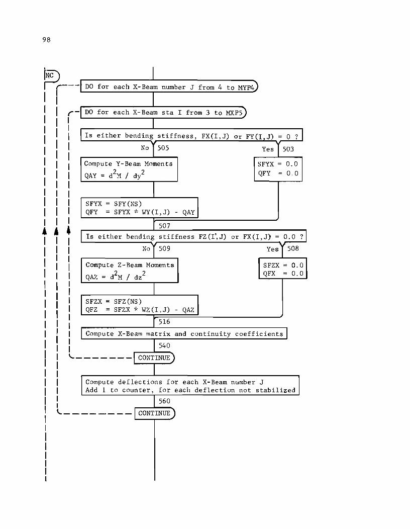
98
I DO for each X-Beam number J from 4 to MYP4)
DO for each X-Beam sta I from 3 to MXP5)
Is either bending stiffness, FX(I,J) Or FY(I,J) = 0 ? No 505 Yes 503
Compute Y-Beam Moments SFYX = 0.0
QAY = d2M / d/ QFY = 0,0
SFYX = SFY (NS) QFY = SFYX '1< WY (I, J) - QAY
• j 4 507
Is either bending stiffness FZ (I~, J) or FX(I,J) = 0.0 ?
No y 509 Yes y 508
Compute Z-Beam Moments SFZX = 0.0
QAZ = d2M / dz2 QFX = 0.0
SFZX = SFZ(NS) QFZ = SFZX * WZ(I,J) - QAZ
516
Compute X-Beam matrix and continuity coefficientsJ
540
--- ---I CONTINUE)
Compute deflections for each X-Beam number J Add 1 to counter, for each deflection not stabilized
560
\.._-------1 CONTINUE)
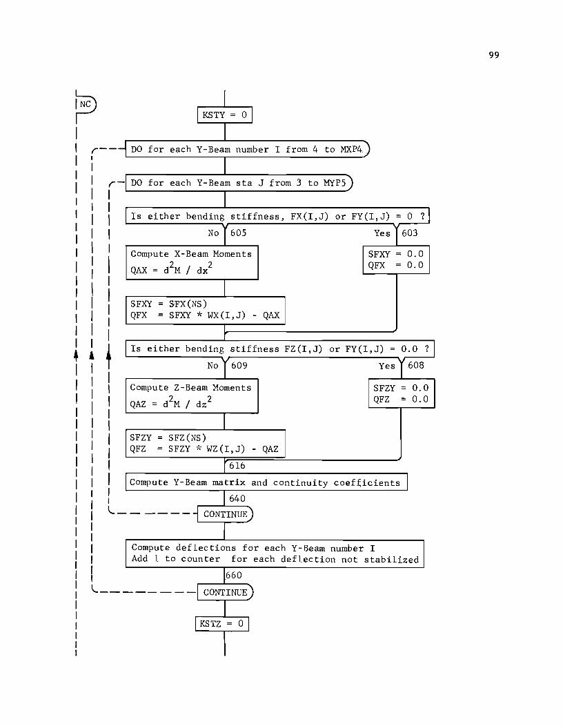
99
~ I 1 KSTY = 0 1
I r-- DO for each Y-Beam number I from 4 to MXP4
I r I I
- DO for each Y-Beam sta J from 3 to MYPS)
1
I I I
I
Is either bending stiffness, FX(I, J) or FY(I, J) = 0 ?
No y 60S Yes 603
Compute X-Beam Moments SFXY = 0.0
QAX = d2M / dx
2 QFX = 0.0
I 1
I I I
I SFXY = SFX(NS) QFX = SFXY ·k WX(I,J) - QAX
I r
+ 1 f I
Is either bending stiffness FZ(I,J) or FY (I , J) = O. 0 ?
No y 609 Yes1608
I Compute Z-Beam Moments SFZY = 0.0
I QAZ = d2M / dz2 QFZ = 0.0
I I 1
I I
SFZY = SFZ(NS) QFZ = SFZY "I: WZ(I,J) - QAZ
I 1 I I
r6l6
Compute Y-Beam matrix and continuity coef~icients J 1640
l. ------ CONTINUE
I Compute deflections for each Y-Beam number I Add 1 to counter for each deflection not stabilized
1660 l. __ - - - - - -I CONTINUE
1 I KSTZ = 0 I
I
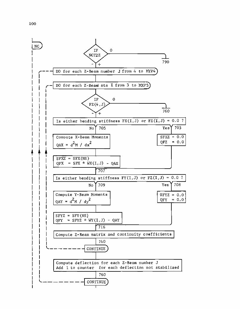
100
r--
rI I I I I I
I I I
• ~
'--
1 I I \.._-
IF 0 NCT2Z .l - +
790
DO for each Z-Beam number J from 4 to MYP4
I DO for each Z-Beard sta I from 3 to iMXP5
IF 0 FZ(4, J) -L - + 760
Is either bending stiffness FX(I,J) or FZ(I,J) = 0.0 ?
No y 705 YesI' 703
Compute X-Beam Moments SFXZ = 0.0
QAX = iM / dx2 QFZ = 0.0
I SFXZ = SFX(NS) QFX = SFX * WX(I,J) - QAX
r 707
Is either bending stiffness FY(I,J) or FZ(I,J) = 0.0 ?
No 1709 Yes 1708
Compute Y-Beam Moments 'SFYZ :: 0.0
QAY = iM / d/ QFY = 0.0:
I SFYZ = SFY(NS) QFY = SFYZ * WY(I,J) - QAY
r 716
Compute Z-Beam matrix and continuity coefficientsl
I 740
------ CONTINUE)
I Compute deflection for each Z-Beam number J Add 1 to counter for each deflection not stabilized
I 760
----- -T CONTINUE) 1
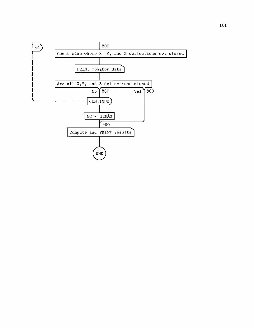
~ I I I • I I I I
800
Count stas where X, Y, and Z deflections not closed
PRINT monitor data
Are all X,Y, and Z deflections closed
Yes 900
l. _________ _
Compute and PRINT results
101

!!!!!!!!!!!!!!!!!!!"#$%!&'()!*)&+',)%!'-!$-.)-.$/-'++0!1+'-2!&'()!$-!.#)!/*$($-'+3!
44!5"6!7$1*'*0!8$($.$9'.$/-!")':!

APPENDIX 4
NOTATION AND LISTING OF PROGRAM LAYER 7

!!!!!!!!!!!!!!!!!!!"#$%!&'()!*)&+',)%!'-!$-.)-.$/-'++0!1+'-2!&'()!$-!.#)!/*$($-'+3!
44!5"6!7$1*'*0!8$($.$9'.$/-!")':!
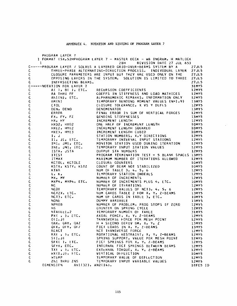
APPENDIX 4. NOTATION AND LISTING OF PROGRAM LAYER 7
PROGRAM lAYER 7 1 FORMAT 15X,52HPROGRAM lAYER 7 - MASTER DECK - WB INGRAM, H lolA HOCK
JUl 65) 1 28H REVISION DATE 27 C-----PROGRAM lAYER 7 SOlV~S A lAYERED GRIO-OVER-BEAMS SYSTEM BY A 27Jl5
lAYER 27Jl5 THE 27Jl5 THREE 27Jl5
C THREE-PHASE ALTERNATING-DIRECTION PROCESS. INDIVIDUAL C CLOSURE PARAMETERS ARE INPUT BUT THEY ARE USED ONLY ON C OPPOSING lAYERS IN THE SYSTEM. SOLUTION IS lIMITED TO C INTERSECTING BEAMS. C-----NOTATION FOR lAYER 7 C AI I, BI ), ETC. C AA THRU FF C ANIIN), ETC. C BMINI C C TOl C DEN, DENO C ERRDR C FX, FY, FZ C HX, HY C HXD2, HYD2 C HXE2, HYE2 C HXE3, HYE3 C I, J C 11, Jl, ETC. C IMl, JMl, ETC. C INl, JNl, ETC. C ISTA, JSTA CITES T C ITMAX C KCTOl, KCTOlZ C KSTX, KSTY, KSTZ C KTAB C l, K, C MX, MY C MXP4, MYP4, ETC. C NC C NCDT C NCT2X, ETC. C NCT3, ETC. C NON~
C NPROB c c C C C C C C C C C C C C C
NS NTABlt:l,2 PXI , ), ETC. o I I, J I QAX, QAY, QAZ OFX, QFY, QFZ REACT RXI ,I, ETC. SII,JI SFXI I, ETC. SFYX, ETC. TXI , I, ETC. WXII,JI, ETC. WHMP ZNl THRU ZN5
DIMENSION ANl(32),
RECURSION COEFFICIENTS COEFFS IN STIFFNESS AND lOAD MATRICES ALPHANUMERIC REMARKS, INFORMATION ONLY TEMPORARY BENDING MOMENT VALUES (N=1,9) CLOSURE TOLERANCE, X VS Y DEFlS DENOMINATOR FI~Al ERROR IN SUM OF VERTICAL FORCES ijENDING STIFFNESSES INCREMENT lENGTH ONE HALF OF INCREMENT lENGTH INCR~MENT lENGTH SQUARED INCREMENT lENGTH CUBED STATION NUMBERS, X,Y DIRECTIONS TEMPORARY INTERNAL INPUT STATIONS MONITOR STATION USED DURING ITERATION TEMPORARY INPUT STATION VALUES OUTPUT STA NUMBERS
27Jl5 31MY5 12MY5 12MY5 12MY5 13MY5 12MY5 13MY5 12MY5 13MY5 12MY5 10MY5 10MY5 10MY5 12MY5 12MY5 12MY5 12MY5 12MY5
PROGRAM TERMINATION TEST = 5 MAXIMUM NUMBER OF ITERATIONS ClOSURI:: COUNTERS COUNT OF BEAM NOT STABILIZED NUM OF TABLE 3, 4, 5, 6 TEMPORARY STATION INDEXES NUMB~R OF INCREMENTS
BLANK SPACES 13MY5 AllOWED 12MY5
10MY5 10MY5 12MY5 12MY5 12MY5
NUMBER OF INCREMENTS PLUS 4, [TC. NUMBER OF ITERATIONS TEMPORARY VALUES OF NCT3, 4, 5, 6 NUM CARDS TABLE 2 FOR X, y, Z-BEAMS NUM UF CARDS IN TABLE 3. ETC. DUMMY VARIABLE NUMBER OF PROBLEM, PROG STOPS IF ZERO COUNTER ON SPRI~G CYCLE TEMPORARY NUMBER OF TABLE AXIAL FORCE, X, Y. Z-BEAMS TRANSVERSt FO~CE PER MESH POINT H • SECOND DERIV Bioi, X, Y, Z FICT lOADS IN X. y, Z-BEAMS NET TKANSVERSE FORCE ROTATIONAL RESTRAINT, X, Y. Z-BEAMS SPRING SUPPORT, VALUE PER MESH POINT FICT SPRINGS FOR X, Y, [-BEAMS INTERNAL FICT SPRINGS BETWEEN BEAMS EXTt:RNAl TORQUE, X, Y, Z-BEAMS VERTICAL DEFLECTION TI::MPORARY VAlUI:: OF DEFll::CTION TEMPORARY INPUT VARIABLE VALUES
AN21141.
105
10MY5 12MY5 12MY5 13MY5 10MY5 13MY5 12MY5 12MY5 31MY5 12MY5 12MY5 13MY5 13MY5 12MY5 12MY5 12MY5 12MY5 12MY5 12MY5 lOMY5 12MY5 12MY5 18FE5 10
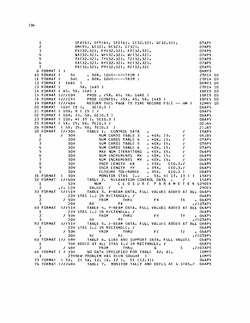
106
1 2 3 4 5 6 7
6 FORMAT 10 FORMAT 11 FORMAT 12 FORMAT 13 FORMAT 14 FORMAT 15 FORMAT 16 FORMAT 19 FORMAT 20 FORMAT 21 FORMAT 22 FORMAT 23 FORMAT 25 FORMAT 26 FORMAT 30 FORMAT
1 2 3 4 5 6 7 8 9 1
31 FORMAT 32 FORMAT
1 2
33 FORMAT 1 2 3
43 FORMAT 1 2 3
53 FORMAT 1 2 3
63 FORMAT 1 2
64 FORMAT 1
73 FORMAT 74 FORMAT
I I 5H
SFXI61, SFYI61, SFZI61, SI32,321, BM191, A1321, B1321, C1321, FXI32,321, FYI32,32), FZI32,32', WXI32,32', WYI32,32', WZI32,321, TXI32,321, TYI32,321, TZI32,321, RXI32,32', RYI32,32', RZI32,321, PXI32,32', PYI32,321, PZ132,321
I 5H1 , 80X, 10HI-----TRIM , 80X, 10HI-----TRIM
I 16A5 I 5X, 16A5 I I A5, 5X, 14A5 I III110H PROB , 15X, A5, 5X, 14A5 ,
0132,321,
111117H PROB ICONTD), 15X, A5, 5X, 14A5 I
07AP5 07AP5 07AP5 07AP5 07AP5 07AP5 07AP5 04MY3 27FE4 ID 27FE4 ID 04MY3 I D 27FE4 ID 18FE5 ID 18FE5 ID 18FE5 ID
111148H RETURN THIS PAGE TO TIME RECORD FILE -- HM I 12MR5 ID 06AP5 08AP5 06AP5 08AP5 02JA4 21JA5 15AP3 04JA5 07AP5 07AP5 07AP5 06AP5 06AP5 06AP5 06AP5 06AP5 06AP5 15AP3 15AP3
1101 15', 3E10.3 I I lOX, 1'1 I 15 I I I lOX, 15, 5X, 6E10.3 I I lOX, 41 15 I, 5EIO.3 I I 5X, 15, 5X, 7E10.3 I
I 5X, 15, 5X, 7E10.3 ) 11130H TABLE 1. CONTROL DATA I I 30H NUM CARDS TABLE 3 ,40X, 15, I
30H NUM CARDS TABLE 4 ,40X, 15, I 30H NUM CARDS TABLE 5 ,40X, 15, I 30H NUM CARDS TABLE 6 ,40X, 15, I 30H MAX NUM ITERATIONS ,40X, 15, I 30H NUM INCREMENTS MX ,40X, 15, I 30H NUM INCREMENTS MY ,40X, IS, I 30H INCR LENGTH HX ,35X, EIO.3,1 30H INCR LENGTH HY ,35X, E10.3,1 30H CLOSURE TOLERANCE ,35X, E10.3 I
I 30H MONITOR STAS I,J , 5X, 41 17, 13 11140H TABLE 2. RELAXATION CONTROL DATA I
52H NUM C LOS U REP A RAM E T E R S29DE4 29DE4
ALL 06AP5 06AP5
,I, 12H VALUES I I 11151H TABLE 3. X-BEAM DATA, FULL VALUES ADDED AT
22H STAS I,J IN RECTANGLE, I I 50H FROM THRU FX TX
20H RX PX 11151H TABLE 4. Y-BEAM DATA, FULL VALUES ADDED AT
22H STAS I,J IN RECTANGLt, I I 50H FkOM THRU FY TY
20H RY PY 11151H TABLt 5. Z-BEAM DATA, FULL VALUES ADDED AT
22H STAS I,J IN RECTANGL[, I I 50H FROM THRU FZ TZ
20H RZ PZ III 48H TABLE 6. LUAD AND SUPPORT DATA, FULL VALUES
35H ADDED AT ALL STAS I,J IN RECTANGLE, I I 48H FROM THRU Q S I 33H NO DATA SPECIFIED FOR TABLE A2, AI,
27HNEW PROBLEM HAS BEEN SOUGHT I I 5X, 21 5X, 12, IX, 12 I, 51 E12.3',
, 06AP5 ,/107AP5
ALL 06AP5 06AP5
, 06AP5 ,/107AP5
ALL 08AP5 06AP5
, 06AP5 ,/107AP5
06AP5 06AP5
,1107AP5 10MY5 10MY5 06AP5
111148H TABLE 7. MONITOR TALLY AND DEFLS AT 4 STAS,I 06AP5
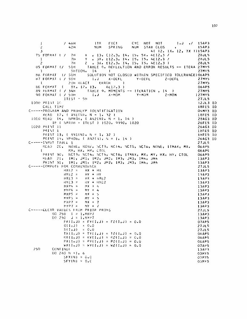
107
1 2 3
I 46H 42H
ITR NUM
FICl SPRING
CYC NOT NOT NUM STAB CLOS ,
I,J ,; 1SAP3 ISAP3
75 FOP",AT I 2
41 12, IX, 12, 7X I I 7H X, 13, E12.3, [4, [5, 5X, 4E12.3 I
7H Y, 3X, ~12.3, [4, 15, IS, 4£12.3 I 7H Z, 3X, E12.3, 14, 15, 15, 4E12.3 )
»15AP3 28JL5 28JL5 28JLS
85 FORMAT 1
~6 FLJRt'lAT H7 FOR~AT
II ~lH TAHLE B. OEFLELTION AND ERROR RESULTS -- ITERA 27MY5 27MY5
WITHIN SPECIFIED TOL£RANCE)06AP5 5HTION, 14 )
II 51H SOLUTIO~ NOT CLOSED I I SOH I,J X-DEFL Y-DEFL I-DEFL 27MY5
I B8 FOR""AT 89 FUR,"'1AT 90 FOR)4AT
2DH RlACT ERROR I I ex, 12, 13, 6[12.3)
I I 34H TAHlE 9. MOMENTS ( I 50H I,J X-MOM
ITEST 511 1000 PRWT H
CAll Tll'E C-----PROGRAM AND PROHlEM IDE~TIFICATION
READ 12, I A~l(;'n, N = 1, 32 )
ITERATION, 14 I V-MOM I-MOM
1010 R[AU 14, NPROri, ( AN2IN), N = 1, 14 ) IF I NPR[)t\ - IHST ) 1020, Q990, 1020
1020 PRINT 11 PRI\T 1 Pin NT PRINT
C----- I ,\lPU T RCAD
1
13, ( A,"lllN). N '" 1, 32 I 1~, ~PMOt\, ( AN2(~), ~ = I, 14 ) TABU: 1 2C, NONE, ND\lt:, '~CT3, NCT4, '\jCTS, NCTo, NONE, (TMAX, MX.
MY, HX. HY, [TOl PRINT 30, NCT3, !\JCT4, :IICTS, NCT6, ITMAX, MX, MY, HX, HY, CTOL RI:AD 21, IMI. J"'l, I r-',2 , JM2, 1M3, J"'3, IM4, J"'14 PRINT 31, IMl, JMl, 1M2, JM2, 1M3, JM3, 1"'14, JM4
C-----COMPUTE FOR CONVENieNCE HXc7 HX .. HX HY!:: 2 HX 1:3 HY[3 MXP4 f"YP4 '" MXP5 ~\YP 5 tJ XP7
HY " HY HX .. hXt2 HY " HYE2 f'lX ~ 4 ~Y ~ 4 MX ~ 5 MY ~ 5 MX ~ 7
t-Yf'7 MY ~ 7 C-----CLEAR VAluES F RUM PR IDR PROBS
00 250 I '" l,~XP7
250
DQ 250 J = 1,MYP7 FX(I.J) = FYII,J) QII,J) 0.0 SII,J) 0.0 TX(I,J) TYII,J) RX ( 1, J ) K Y I I, J ) PX(I,J) PYII,J) nX(I.J) '" WYII,J)
CUNTINUE: DO 280 N =1, 6
::,FXIN) 0.0 SFYIN) '"' O.C
FZII,J)
TlII.J) RllI,J) PZ((,J) '" Wl(l,J) '"
0.0
0.0 0.0 0.0 0.0
27MY5 06AP5 27MY5
) 27MY5 27JL5 12JL3 10 I8FE5 10 04MY3 10 18FE5 10 28AG3 10 26FE5 10 26AG3 10 18FE5 10 ISH5 ID 26AG3 10 27JL5 06AP5 06AP5 06AP5 l3AP3 l3AP3 27JL5 l3AP3 13AP3 l3AP3 13AP3 l3AP3 l3AP3 DAP3 l3AP3 13AP3 l3AP3 27JL5 13AP3 13AP3 07AP5 27JL5 27JL5 06AP5 06AP5 06AP5 07AP5 13AP3 03MY5 03MY5 03MY5
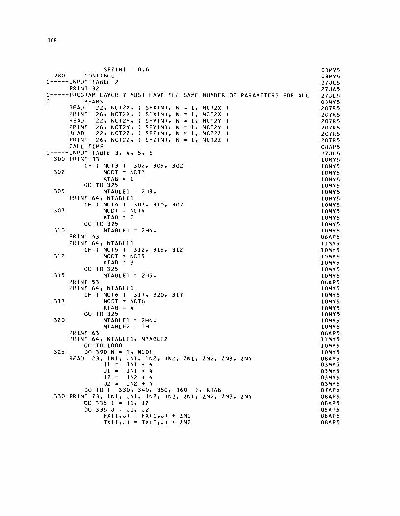
108
SFllNI 280 CONTINUE
C-----INPUT TABLE 2 PRINT 32
0.0
C-----PROGRAM LAYEK 7 MUST HAVE THe SAME NUMBER OF PARAMETERS FOR ALL C BEAMS
READ 22, PRINT 2b, READ 22, PRINT 2b, READ 22, PRINT 2b, CALL TIME
NCT2X, NCT2X, NCT2Y, NCT2Y, NCT 2l, NCT2l,
C-----INPUT TABLE 3, 4, 300 PRINT 33
5,
SFXINI, N SFXINI, N SFYINI, N SFYINI, N SFlINI, N SFlINI, N
b
I F I 302
NCB NCDT KTAB
302, 305, 302 NCB 1
GO TO 325 305 NTABLEI = 2H3.
PRINT b4, NTABLEI IF I NCT4 I 307, 310, 307
307 NCDT NCT4 KTAB 2
GO TO 325 310 NTABLEI = 2H4.
PRINT 43 PRINT b4, NTABL~l
IF I NCT5 I 312, 315, 312 312 NCDT NCT5
KTAB 3 GO TO 325
315 NTABLEI = 2H5. PRINT 53 PRINT b4, NTABLEI
IF I NCTb I 317, 320, 317 317 NCDT NCTb
KTAB 4 GO TO 325
320 NTABLEI 2Hb. NT ABL E2 IH
PRINT b3 PRINT b4, NTABLEl, NTABLE2
GO TO 1000 325 DO 390 N = 1, NCDT
1 , NCT2X 1 , NCT2X 1 , NCT2Y 1 , ~CT2Y
= 1, NCT2l 1 , NCT2l
READ 23, INl, JNl, IN2, JN2, lNl, lN2, lN3, lN4 11 INl+4 Jl JNl+4 12 I N2 + 4 J2 JN2 + 4
GO TO I 330, 340, 350, 3bO I, KTAB 330 PRINT 73, INl, JNl, IN2, JN2, lNl, lN2, l1ll3, lN4
DO 335 I = ll, 12 DO 335 J = Jl, J2
FXII,JI FXII,JI + lNl TXII,JI = TXII,JI + llll2
03MY5 03MY5 27JL5 27JA5 27JL5 03MY5 207R5 207R5 207R5 207R? 207R5 207R5 08AP5 27JL5 10MY5 10MY5 10MY5 10MY5 10MY5 10MY5 10MY5 10MY5 10MY5 10MY5 10MY5 10MY5 ObAP5 llMY? 10MY5 10MY5 10MY5 10MY5 10MY5 ObAP5 10MY5 10MY5 10MY5 10MY5 10MY5 10MY5 10MY5 ObAP5 llMY5 10MY5 10MY5 08AP5 03MY5 03MY5 03MY5 03MY5 07AP5 08AP5 08AP5 08APS U8AP5 08AP5
109
RXII,JI = RXII,JI + ZN3 08AP5 PXII,JI = PXII,JI + ZN4 08AP5
335 CONTINUE 06AP5 336 IF I N - NCDT I 390, 337, 337 10MY5 337 PRINT 43 14MY5
IF I NCT4 338, 339, 338 14MY5 338 NCDT NCT4 10MY5
KTAB 2 10MY5 GO TO 325 10MY5
339 NTABLEl = 2H4. 10MY5 PRINT 64, NTABLEI 10MY5
GO TO 347 10MY5 340 PRINT 73, INl, JNl, IN2, JN2, ZNl, ZN2, ZN3, ZN4 08AP5
DO 345 I = I 1 , 12 08AP5 DO 345 J = J 1, J2 08AP5
FYII,JI FYII,J) + ZNl 08AP5 TYII,JI TYII,JI + ZN2 08AP5 RYII,JI RYII,JI + ZN3 08AP5 PY I I, J I PYII,JI + ZN4 08AP5
345 CONTINUE 06AP5 346 IF I N - NCDT ) 390, 347, 347 10MY5 347 PRINT 53 14MY5
IF I NCT5 348, 349, 348 14MY5 348 NCDT NCT5 10MY5
KTAB 3 10MY5 GO TO 325 10MY5
349 NT ABLEl = 2H5. 10MY5 PRINT 64, NTABLEI 10MY5
GO TO 357 10MY5 350 PRINT 73, INl, JNl, IN2, JN2, ZNl, ZN2, ZN3, ZN4 08AP5
DO 355 I = I 1 , 12 08AP5 DO 355 J = J 1, J2 08AP5
FZII,JI FZII,J) + ZNl 08AP5 TZII,JI TZII,J) + ZN2 08AP5 RZ I I, J I = RZII,JI + ZN3 08AP5 PZ I I, J I = PZII,JI + ZN4 08AP5
355 CONTINUE 06AP5 356 IF ( N - NCDT I 390, 357, 357 10MY5 357 PRINT 63 14MY5
IF ( NCT6 358, 359, 358 14MY5 358 NCDT NCT6 10MY5
KTAB 4 10MY5 GO TO 325 10MY5
359 NTABLEI = 2H6. 10MY5 NTABLE2 = IH 10MY5
PRINT 64, NTABLEl, NTABLE2 10MY5 GO TO 1000 10MY5
360 PRINT 73, INl, JNl, IN2, JN2, ZN 1, ZN2 08AP5 DO 365 I = I 1, 12 08AP5 DO 365 J = J 1, J2 08AP5
Q I I, J I Q I I, J I + Z N 1 08AP5 S I I, J I = S ( I, J I + ZN2 08AP5
365 CONTINUE 06AP5 390 CONTINUE- 06AP5
CALL TI"'E: 08AP5 KTA13 0 06AP5
110
PRINT 74, IM1, JM1, 1M2, JM2, 1M3, JM3, IM4, JM4 C-----BEGIN MAIN SOLUTION
06APS 27JLS 2SAG4 27APS 2SAG4 20MRS
NS = 0 00 860 NC = 1, ITMAX
NS = NS + 1 IF I NS-NCT2X I SOl, 501, SOO
SOO NS = 1 2SAG4 C-----SOLVE X-BEAMS 27JLS
2SAG4 01MA3 13AP3 27JLS 24FES 29MRS 17FES 17FES 01MA3 01MA3 01MA3 07APS 31DE4 27JLS 21MYS 21MYS 24MYS 24MYS 07JES 29MRS 29MRS 20MRS 29MRS 07APS 17FES 21JAS 20MRS 27JLS
501 KSTX 0 DO 560 J 4, MYP4 DO S40 I 3,MXPS
C-----ESTABLISH ITERATION CONTROL PARAMETERS FOR X BEAMS
503
50S
1 506
S07 S08
S09
1 2 3 4 5 6
1 S10
1 2 3 4 S 6
IF I FXII,JI .. FYII,JI I SOS, S03, SOS SFYX = QFY = 0.0
GO TO S07 DO S06 N = 1, 3
L J + N - 2 BMIN+3) FYII,l) • I WYII,L-ll - WYII,L) -WY(I,L)
+ WYII,L+lI I I HYE2 CONTINUt
QAY = I BMI41 -2.0 • BMISI + BMI61 I I HY + 1- 0.2S • HY • RYII,J-lI • WYII,J-21 + 0.2S • HY • I RYII,J-lI + RYII,J+ll1. - 0.2S • HY • RYII,J+lI • WYII,J+21 - HYE2 • PYII,J) • WYII,J-lI
WYII,JI
+ HY E 2 • I P Y I I , J) + P Y I I , J + 1 ) - HYE2 • PYII,J+lI • WYII,J+lI
• WYII,J) I HYE3
SFYX SFYINS) QFY = SFYX • WYII,J) - QAY
IFI FZII,J). FXII,J) I S09, S08, S09 SFZX = OFZ = 0.0
GO TO S16 DO 510 N = 1, 3
K = I + N - 2 BMIN+6) = FZIK,J).I WZIK-l,JI - 2.0.WZIK,J) +
WZIK+l,J) ) I HXE2 07APS CONTINUE
QAZ I BMI7I - 2.0 .BM181 + BMI91 1/ HX 20MRS + I - 0.2S • HX • RZlI-l,JI • WZII-2,JI 27JLS + 0.2S. HX • I RZlI-l,JI + RZII+l,JI I. WZ(I,JI 21MYS - 0.2S. HX • RZII+l,JI • WZII+2,JI 21MYS - HXE2 • PZII,JI • WZlI-l,JI 24MYS + HXE2 • I PZII,JI + PZII+l,JI • WZII,JI 24MYS - HXE2 • PZII+l,JI • WZII+l,JI I HXE3 27MYS
SFZX SFZINSI 29MRS OFZ = SFlX.WZ I I, J I - QAZ 29MRS
C-----COMPUTE S16
X-BtAM MATRIX COEFFS 27JLS AA FXlI-l,JI - 0.2S • HX • RXlI-l,JI ObAPS
1 2 3
BB - 2.0 • I FXlI-l,JI + FXII,JI 1- HXE2 • PXII,JI 08APS CC FXlI-l,JI + 4.0 • FXII,JI + FXII+l,JI 13AP3
DD EE FF =
+ HXE2 • I PXII,JI + PXII+l,JI I OSMYS + 0.2S .. HX • I RXlI-l,JI + RXII+l,JI I OSMYS + HXE3 • SI I ,J I + HXE3 • I SFYX + SFZX I OSMYS - 2.0 • I FXII,JI + FXII+l,JI 1- HXE2 • PXII+l,JI07APS
FXII+l,JI - 0.2S .. HX. RXII+l,JI ObAPS HXE3. I OII,J) + QFY + QFl 27JLS
1 2 3
C-----COMPUTE
IF 521
-0.5/HX -ITXI 1-1,J)-TXI 1+1,J) -0.5/HY -ITYII.J-1I-TYII,J+1I) -0.5/HX -ITZll-1,J)-TZII+1,J»
X-BEAM CONTINUITY COEFFS E AA - BII-2) + BB DEN E - BII-1I + AA - CII-2) + CC IDEN) 531, 521, 531 o 0.0
GO TO 532 531 532
o C I I ) B I I ) A I I)
540 CONTINUE
- 1.0 o o o
/ DEN - EE - I E - I E
- C 1 1-11 + DO - AII-1I + AA - AII-2) - FF )
C-----COMPUTE X-BEAM DEFLS DO 550 L = 3,MXP5
I MX + 8 - L IHEMP WXII,J) WXII.J) All) + Bill - WXII+1,J) + CII) - WXII+2,J)
C-----COUNT STAS WHERE X-BEAMS NOT STABILIZED
C
545 546 550 560
IF I FXII,J) - FYII,J) ) 545, 550, 545 IF I ABSF I WXII,J) - WTEMP ) - CTOL
KSTX KSTX + 1 CONTINUE CONTINUI::
)550, 550, 546
C-----SOLVE Y-~EAMS KSTY 0
DO 660 I 4, MXP4 DO 640 J 3,MYP5
C-----ESTABLISH ITERATION CONTROL PARAMETERS FOR Y BEAMS IFI FXII.J) - FYII,J) ) 605,603,605
603 SFXY = QFX = 0.0 GO TO 607
605 DO 606 N = 1, 3 K = I+N-2 BMIN) FXIK,J) - WXIK-l,J) - WXIK,J) - WXIK,J)
1 + WXIK+1,J) ) / HXE2 606 CONTINUE
QAX = I BMIl! - 2.0 - BM(2) + BM(3» / HX 1 + 1 - 0.25 - HX - RXll-1,J) - WXII-2,J) 2 + 0.25- HX - I RXII-1,J) + RXII+1,J) ) - WXII,J) 3 - 0.25- HX - RXII+1,J) - WXII+2,J) 4 -HXE2 - PXII.J) - WXlI-1.J) 5 + HXE2 - I PXII,J) + PXII+1,J) ) - WXII,J) 6 - HXE2 - PXII+1,J) - WXII+1,J) ) / HXE3
SFXY = SFXINS) QFX = SFXY-WXII,J) - QAX
607 IFI FZII,J)- FYII,J) ) 609,608,609 608 SFZY = QFl = 0.0
GO TO 616 609 DO 610 N = 1, 3
K = I + N - 2 BMIN+6) = FZIK,J)-I WZIK-1,J) - 2.0-WZ(K,J) +
1 WZIK+1,J) ) / HXE2 610 CONTINUE
21MY5 21MY5 2lMY5 27JL5 13AP3 13AP3 13AP3 01MA3 13AP3 13AP3 13AP3 13AP3 13AP3 13AP3 27 JL5 13AP3 13AP3 13AP3 13AP3 27JL5 13AP3 25AG4 13AP3 13AP3 13AP3
27JL5 29AP3 01MA3 13AP3 27JL5 24FE5 20MR5 17FE5 17FE5 01MA3 01MA3 01MA3 07AP5 31DE4 27JL5 21MY5 21MY5 24MY5 24MY5 27MY5 20MR5 20MR5 207R5 29MR5 07AP5 17FE5 19JA5 20MR5 27JL5 07AP5
111
112
1 2 3 4 5 6
QAl I BMI71 - 2.0 .BMe81 • BMI91 II HX + 1- 0.25 • HX • RlII-1,JI • WlCl-2,JI + 0.25. HX • I RlII-1,JI + RlII+1,JI 1 • WlII,J) - 0.25. HX • RlII+1,JI • WlII+2,JI - HXE2 • PlII,JI • WlII-1,JI + HXE2 • I PlII,JI + PlII+1,JI - HXE2 • PlII+1,JI • WlII+1,J)
• Wl I I, J I I HXE 3
SFlY SFlINSI QFl = SFlY.WlII,JI - QAl
C-----COMPUTE Y-BEAM MATRIX COEFFS 616 AA FYII,J-l) - 0.25 • HY • RYII,J-l)
1 2 3
BB - 2.0 • I FYII,J-1) + FYII,JI I - HYE2 • PYII,JI CC FYII,J-l) + 4.0. FYII,J) + FYII,J+l)
+ HYE2 • I PYII,JI + PYII,J+l) I + 0.25 • HY • I RYII,J-l) + RYII,J+l) + HYE3 • SII,JI • HYE3 • I SFXY + SFlY
20MR5 27JL5 21MY5 21MY5 24MY5 24MY5 27MY5 29MR5 29MR5 27JL5 06AP5 08AP5 13AP3 05MY5 05MY5 05MY5
DD EE FF
- 2.0 • I FYII,JI + FYII,J+11 1- HYE2 • FYII,J.11 - 0.25 • HY • RYII,J+1)
PYII,J+1108AP5
1 2 3
= HYU. I QII,JI + QFX + QFl -0.5/HX .nxII-1,JI- TXII+1,JII -0.5/HY .ITYII,J-1'- TYII,J+111 -0.5/HX .ITlII-1,JI- TlII+1,JII
C-----COMPUTE Y-BEAM CONTINUITY COEFFS
621
631 632
E AA • BIJ-21 + BB DEN E. BIJ-11 + AA • CIJ-2) + CC
IF IDEN) 631, 621, 631 D 0.0
GO TO 632 D C I J I BIJ) A I J I
- 1.0 D D D
I DEN • EE
• I E • I E
• C I J-1) + DD • AIJ-11 + AA • AIJ-21 - FF )
640 CONTINUE C-----COMPUTE Y-BEAM DEFLS
DO 650 L = 3,MYP5 J = MY + 8 - L WTEMP WYII,JI
06AP5 21MY5 21MY5 26MY5 21MY5 27JL5 13AP3 13AP3 13AP3 01MA3 13AP3 13AP3 13AP3 13AP3 13AP3 13AP3 27JL5 13AP3 13AP3
WYII,JI AIJ) + BIJI. WYII,J+l) + CIJI • WYII,J+21 13AP3 13AP3 27JL5 13AP3 25AG4 13AP3
C-----COUNT STAS WHERE Y-BEAMS NOT STABILIlED
645 646 650 660
IF I FXII,JI • FYII,JI I 645, 650, 645 IF I ABSF I WYII,JI - WTEMP 1- CTOL 1650, 650, 646
KSTY KSTY + 1 CONTINUE CONTINUE
C C-----SOLVE l BEAMS
700
KSTl = 0 IF I NCT2l I 700, 790, 700 DO 760 J = 4, MYP4 DO 740 I = 3, MXP5
C-----THE FOLLOWING TEST SEEKS ONLY THE END OF A l-BEAM. C l-BEAMS ARE NOT USED, REMOVE THE FOLLOWING CARD.
IF I Fll4,JI I 702, 760, 702 C-----ESTABLISH ITERATION CONTROL PARAMETERS FOR l BEAMS
702 IF I FXII,JI • FlII,J) 1705,703, 70S 703 SFXl = QFX = 0.0
13AP3 13AP3 03MY5 03MY5 20MR5 26AP5 26AP5 26AP5
IF FULL LENGTH27JL5 27JL5 05MY5 27JL5 03MY5 26AP5
705
1 706
707 708
709
1 2 3 4 5 6
1 710
1 2 3 4 5 6
GO DO.
TO 707 706 N ::: 1, 3
K ::: I + N - 2 BMIN) ::: FXIK,J).I WXIK-l,J)
WXIK+l,J) ) I HXE2 - 2.0.WXIK,J) +
CONTINUE
IF
QAX = I BMIll - 2.0. BM(2) + BM(3) ) I HX + I - 0.25 • HX • RXll-l,J) • WXII-2,J) + 0.25. HX • I RXll-l,J) + RXII+l,J) ) • WXII,J) - 0.25. HX • RXII+l,J) • WXII+2,J) -HXE2 • PXII,J) • WXll-l,J) + HXE2 • I PXII,J) + PXII+l,J) - HXE2 • PXII+l,J) • WX(I+l,J)
SFXZ = SFXINS) QFX = SFXZ.WXII,J) - QAX FYI I,J).FZI I,J) ) 709, 708, 709 SFYZ ::: QFY ::: 0.0
• W X I I ,J ) I HXE3
GO TO 716 DO 710 N = 1, 3
L = J + N - 2 BMIN+3) = FYI I,Ll
I HYE2 WYII,L-1l-2.0.WYII,L) + WYII,L+ll)
CONTINUE QAY::: I BM(4) -2.0 • BM(5) + BM(6) ) I HY
+ I - 0.25 • HY • RYII,J-ll • WYII,J-2) + 0.25 • HY • I RYII,J-1) + RY(I,J+1». WYII,J) - 0.25 • HY • RYII,J+1) • WYII,J+2) - HY E 2 • P Y I I , J) • W Y I I , J - 11 + HYE2. I PYII,J) + PYII,J+1) - HYE2 • PYII,J+1) • WYII,J+1)
SFYZ SFYINS)
• WYII,J) I HYE3
26AP5 26AP5 21JA5 21JA5 21JA5 26AP5 31DE4 27JL5 21MY5 21MY5 24MY5 24MY5 28MY5 29MR5 20MR5 26AP5 26AP5 26AP5 26AP5 31DE4 27JL5 31DE4 26AP5 31DE4 27JL5 21MY5 21MY5
QFY::: SFYZ.WYII,J) - QAY C-----COMPUTE I-BEAM MATRIX COEFFS
24MY5 24MY5 27MY5 20MR5 20MR5 27JL5 26AP5 716 AA Flll-l,J) - 0.25 • HX • RZll-l,J)
1 2 3
1 2
BS - 2.0 • I FIII-1,J) + FZII,J) ) - HXE2 • CC = FZII-1,J) + 4.0 • FZ(I,J) + FZII+l,J)
+ HXE2 • I PZ(I,J) + PZII+l,J) )
DD EE FF
+ 0.25 • HX • I RZll-l,J) + RZ(I+l,J) + HXE3 • SII,J) + HXE3 • I SFXZ + SFYZ - 2.0 • I FZII,J) + FZII+l,J) ) - HXE2.
= FZII+1,J) - 0.25 • HX • RZII+l,J) ::: HXE3. I OII,J) + QFX + QFY -0.5/HX .1 TXI l-l,J )-TXI l+l,J» -0.5/HY·ITYII,J-1)-TYII,J+1»
3 -O.5/HX .ITlll-l,J)-TZII+l,J» C-----COMPUTE Z-BEAM CONTINUITY COEFFS
721
731 732
740
E AA • BII-2) + BB DEN E. BlI-l) + AA • CII-2) + CC
IF IDEN) 731, 721, 731 D 0.0
GO TO 732 D C I I ) B I I) A I I )
CONTINUE
- 1.0 I DEN D • EE D • I E D • ( E
• C I 1-1) + DD • A I 1-1) + AA • A I 1-2) - F F )
PZII,J) 08AP5 20MR5 05MY5 05MY5 05MY5
PZII+1,J)08AP5 06AP5 21MY5 21MY5 21MY5 21MY5 27JL5 13AP3 13AP3 26AP5 26AP5 26AP5 26AP5 26AP5 13AP3 13AP3 26AP5
113
114
C-----COMPUTE Z-BEAM DEFLS DO 750 L = 3,MXP5
1 MX + 8 - L ~o/TEMP = WZII,J) WZII,J) = All) + BIll-WZII+1,J) + CIll-WlII+2,J)
C-----COUNT STAS WHERE Z-BEAMS NOT STABILIZED IFI FZII,J) ) 745, 750, 745
745 IF I ABSF I WZII,J) - wTEMP ) - CTOL 1750, 750, 74b 74b KSTZ = KSTZ + 1 750 CONTINUE 7bO CONTINUE 790 CONTINUE
C-----COUNT STAS WHERE DEFLS NOT CLOSED KCTOL 0 KCTOll = 0
DO 850 1 = 4, MXP4 DO 850 J = 4, MYP4 IF I FXII,J) • FYII,J» 810,820,810
810 IF I A8SFI WXII,J) - WYII,J) ) - CTOL) 820,820,815 815 KCTOL = KCTOL + 1 820 IF I FXII,J) + FYII,J) ) • FZII,J» 830, 850,830 830 IF FXII,J» 840, 835, 840 835 IF ABSFI WZII,J) - WYII,J) ) - CTOL 850,850,845 840 IF ABSFI WZII,J) - WXII,J) ) - CTOL 850,850,845 845 KCTOLZ = KCTOLZ + 1 850 CONTINUE
C-----PRINT MONITOR DATA PRINT 75, NC, SFXINS), NS, KSTX, WXIIM1+4,JM1+4),
1 WXIIM2+4,JM2+4), WXIIM3+4,JM3+4), WXIIM4+4,JM4+41, 2 SFYINS), NS, KSTY, KCTOL, WY(IM1+4,JM1+4), 3 WYIIM2+4,JM2+4), WYIIM3+4,JM3+4), wYIIM4+4,JM4+4), 4 SFZINS), NS, KSTI,KCTOLI,wIIIM1+4,JM1+4), 5 wZIIM2+4,JM2+4), WZIIM3+4,JM3+4), wZIIM4+4,JM4+4)
C C-----CONTROL ITERATION PROCESS
IF I KCTOL + KCTOLZ) 900, 900, 8bO 8bO CONT 1 NU E
NC = ITMAX C-----COMPUTE AND PRINT RESULTS
900 CONTINUE PRINT 11 PRINT 1 PRINT 13, I ANlIN), N = 1,32 ) PRINT 1b, NPR08, ( AN2IN), N = 1, 14 I PRINT 85, NC
1 F I K C T OL + K C T OL Z ) 912, 912, 911 911 PRINT 8b 912 PRINT 87
DO 9bO J 3,MYP5 PRINT b
DO 950 I 3,MXP5 ISTA I - 4 JSTA J - 4
DO 940 N 1,3 K = I + N - 2 8MIN) = FXCK,J) • I WXCK-1,J) - WXIK,J) - WXCK,J)
27JL5 2bAP5 13AP3 20MR5 20MR5 27JL5 2bAP5 2bAP5 2bAP5 2bAP5 2bAP5 2bAP5 27JL5 13AP3 20MR5 04MY5 03MY5 03MY5 ObMY5 03MY5 03MY5 03MY5 03MY5 03MY5 03MY5 03MY5 27JL5 ObAP5 25AP3 20MR5 31DE4 207R5 20MR5
27JL5 2bAP5 2bAP5 25AG4 27JL5 2bAP5 08MY3 ID 18FE5 ID 18FE5 ID 28AG3 ID ObAP5 2bAP5 2bAP5 2bAP5 2bAP5 24AP3 2bAP5 18AP3 18AP3 2bAP5 21JA5 01MA3
1
1
1 940
946
1 2 3 4 5 6
1 2 3 4 5 6
1 2 3 4 5 6
BMIN+61
L = J + BMIN+3)
CONTINUE
+ WXIK+1,J) = FZIK,J).I WZIK+1,J) ) N - 2
FYII,L) •
) I HXE2 WZIK-l,J) - 2.0.WZIK,J) + I HXE2
+ WYII,L+l) WYII,L-ll - WYII,L) -WYII,L) ) I HYE2
QAX = I BM I 1) - 2.0 • BM (2) + BM (3)) I HX + 1- 0.25. HX. RXII-1,J) • WXII-2,J) + 0.25. HX • I RXII-1,J) + RXII+1,J) ) • WXII,J) - 0.25. HX • RXII+1,J) • WXII+2,J) -HXE2. PXII,J) • WXII-1,J) + HXE2 • I PXII,J) + PXII+1,J) ) • WXII,J) - HXE2 • PXII+1,J) • WXII+l,JI ) I HXE3
QAY = I BM(4) - BM(5) - BM(5) + BM(6) ) I HY + I - 0.25 • HY. RYII,J-ll • WYII,J-2) + 0.25 • HY. I RYII,J-ll + RYII,J+l)). WYII,J) - 0.25 • HY • RYII,J+ll • WYII,J+2) - HYE2 • PYII,J) • WYII,J-1) + HYE2 • I PYII,J) + PYII,J+ll ) • WYII,J) - HYE2 • PYII,J+ll • WYII,J+ll ) I HYE3
QAZ = I BMln - BM(8) - BM(8) + BM(9) ) I HX + 1- 0.25 • HX • RZII-1,J) • WZII-2,J) + 0.25. HX • I RZII-1,J) + RZII+1,J) ) • WZII,J) - 0.25. HX • RZII+1,J) • WZII+2,J) - HXE2 • PZII,J) • WZII-1,J) + HXE2 • I PZII,J) + PZII+1,J) - HXE2 • PZII+1,J) • WZ(I+1,J)
REACT = QAX + QAY + QAZ IF I FXII,J) • FYII,J) I 948, 946,948
ERROR 0.0 GO TO 94'J
• WZII,J) I HXE3
C-----STATEMENT 948 MAY NOT OPERATE PROPERLY ON COMPUTERS OTHER THAN C CDC 1604 WHERE ZERO DIVIDED BY ZERO IS ZERO.
01MA3 20MR5 27JL5 21JA5 01MA3 01MA3 26AP5 31DE4 27JL5 21MY5 21MY5 24MY5 24MY5 27MY5 19JA5 27JL5 21MY5 21MY5 24MY5 24MY5 27MY5 20MR5 27JL5 21MY5 21MY5 24MY5 24MY5 27MY5 21MY5 26AP5 26AP5 26AP5
THE27JL5 27JL5 27JL5 C-----THIS STATEMENT SUMS THE NUMBER OF INTERSECTING BEAMS AT A JOINT.
948 DENO = WXII,J) I WXII,J) + WY(I,J) I WYII,J) + 1 I<IZII,J) I WZII,J)
1 2 3
ERROR QII,J) - REACT - SII,J) • I WXII,J) + WZII,J) + WYII,J) ) I DE NO -0.5/HX. ITXII-1,JI - TXII+1,J)1 -0.5/HY. ITYII,J-ll - TYII,J+ll)
4 - 0.51 HX • I Tli I-I, J) - T ZI 1+1, J ) ) 949 PRINT 88, ISTA, JSTA, WXII,J), WYII,J), WZII,J), REACT, ERROR
WXII-2,J-2)= BM(2)
950 960
WYII-2,J-21= BM(5) WZII-2,J-2)= BM(8)
CONTINUE CONTINUE
PRINT 89, NC PRINT 90
DO 980 J PRINT 6
3, MYP5
DO 970 I 3, MXP5 ISTA = I - 4 JSTA = J - 4
PRINT 88, ISTA,JSTA,WXII-2,J-2) ,WYII-2,J-2) ,WZII-2,J-2)
26AP5 07AP5 21MY5 07AP5 21MY5 21MY5 21MY5 27MY5 27MY5 27MY5 27MY5 26AP5 26AP5 27MY5 27MY5 27MY5 27MY5 27MY5 27MY5 27MY5 27MY5
115
116
970 CONTINUE 27MY5 980 CONT INUE 27MY5
CALL TIME 18FE5 10 GO TO 1010 26AG3 10
9990 corH INU[ 12MR5 10 9999 CONTINUE 04MY3 10
PRINT 11 08MY3 10 PRINT 1 18FE5 10 PRINT 13. ( AN L( N). N 1 t 32 } 18FE5 10 PRINT 19 26AG3 ID END 04MY3 10 END 04MY3 10

APPENDIX. 5
PROGRAM LAYER 7 AND GUIDE FOR DATA INPUT

!!!!!!!!!!!!!!!!!!!"#$%!&'()!*)&+',)%!'-!$-.)-.$/-'++0!1+'-2!&'()!$-!.#)!/*$($-'+3!
44!5"6!7$1*'*0!8$($.$9'.$/-!")':!
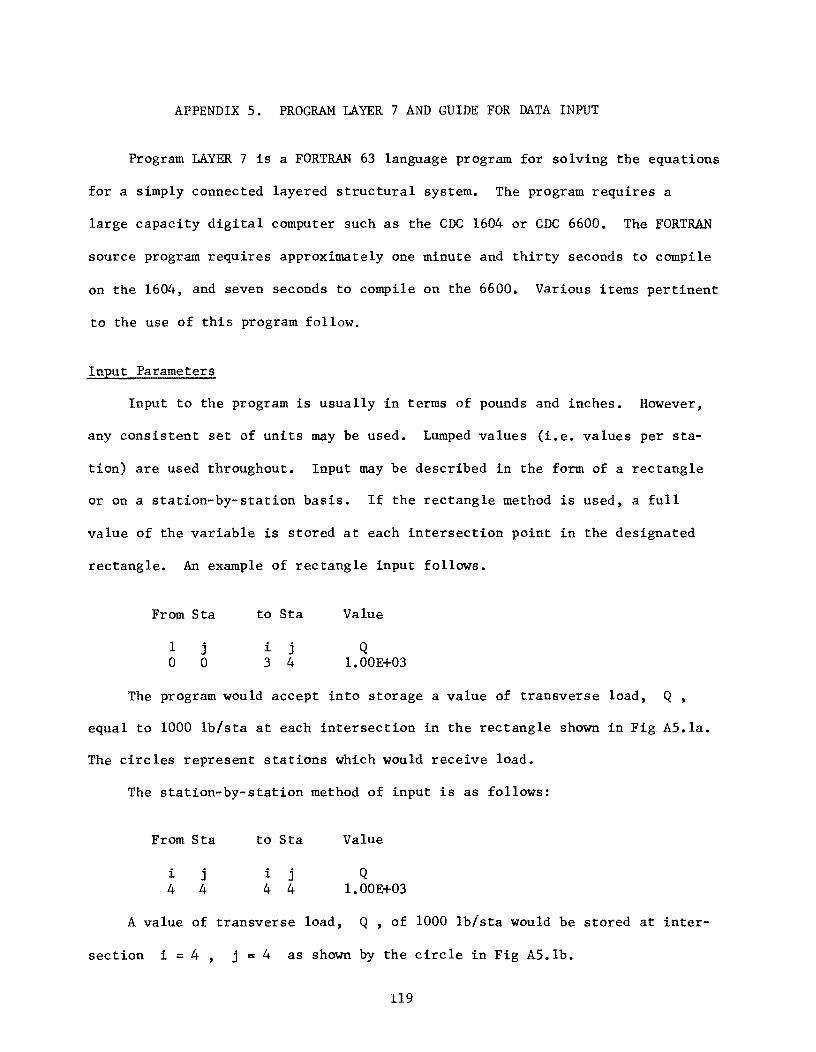
APPENDIX 5. PROGRAM LAYER 7 AND GUIDE FOR DATA INPUT
Program LAYER 7 is a FORTRAN 63 language program for solving the equations
for a simply connected layered structural system. The program requires a
large capacity digital computer such as the CDC 1604 or CDC 6600. The FORTRAN
source program requires approximately one minute and thirty seconds to compile
on the 1604, and seven seconds to compile on the 6600. Various items pertinent
to the use of this program follow.
Input Parameters
Input to the program is usually in terms of pounds and inches. However,
any consistent set of units may be used. Lumped values (i.e. values per sta-
tion) are used throughout. Input may be described in the form of a rectangle
or on a station-by-station basis. If the rectangle method is used, a full
value of the variable is stored at each intersection point in the designated
rectangle. An example of rectangle input follows.
From Sta
1 o
j o
to Sta
i j 3 4
Value
Q 1.00E+03
The program would accept into storage a value of transverse load, Q,
equal to 1000 lb/sta at each intersection in the rectangle shown in Fig A5.la.
The circles represent stations which would receive load.
The station-by-station method of input is as follows:
From Sta
i 4
j 4
to Sta
i j 4 4
Value
Q 1.00E+03
A value of transverse load, Q, of 1000 lb/sta would be stored at inter-
section i = 4, j B 4 as shown by the circle in Fig AS.lb.
119
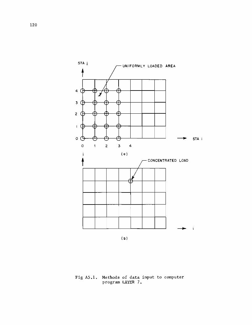
120
STA j UNIFORMLY LOADED AREA
f / C) ,..." i \.,./ i \.. ./ 4
3 ( \. q/
( I' \. \. 2
( I' / /1'\ \.
o \...I \.../ \.../ ----.. STA
o 2 3 4
( a )
t ~ONCENTRATED LOAD r v
I
( b)
Fig AS.l. Methods of data input to computer program LAYER 7.
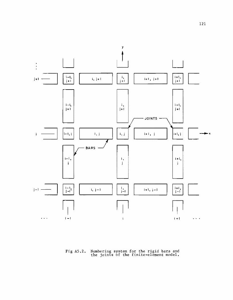
u j+1 =::J [IJ j+1
i-I, j+1
B i-I,
j-I ---==:J [2J j-I-
III i-I
Fig AS.2.
y
~ U it j+ I QJ i+1
i+ I J j+ I § i+1
i, i+l, j+1 j+!
i, j i, j
JOINTS]B i+ I, j I itl, i
BARS
i, i -t I, j
i, j-I I OJ j-I I i+l, j-I @J j-I
III i +1
Numbering system for the rigid bars and the joints of the finite-element model.
121
C
C ~x
C
122
Figure A5.2 shows the manner in which the bars and joints of the model
are numbered. Each bar is numbered "before" its joint. In the x-direction
this puts the bar to the left of the joint and in the y-direction the bar is
shown below its correspondingly numbered joint. It is important to remember
that axial tensions refer to bars so that no tension should be numbered that
would act outside the real system.
All input to the program is cummulative, i.e., if two data cards such as
the one used to create Fig 5.lb were input, the total value of load stored at
stations 1 = 4, j = 4 would be 2 x 10³
lb. Any amount of adding or sub
tracting of data may be done to obtain the desired values at each intersection.
Program Results
The results from the program are arranged in tables. Tables 1, 2, 3, 4,
5, and 6 are reflections of the input data. Table 7 lists the deflection
versus number of iterations at four selected stations. Table 8 gives all de
flections for each x, y, and z-beam plus a reaction term and an error
term. The error term refers to the error in load equilibrium at each inter
section. The error represents the amount of unbalance between the iteration
equation, Eq 3.11, and the equation which must be satisfied, Eq 3.1. The bend
ing moments for each intersecting member are tabulated in Table 9.
GUIDE FOR DATA INPUT FOR LAYER 7
with Supplementary Notes
extract from
A FINITE-ELEMENT METHOD FOR BENDING ANALYSIS OF LAYERED STRUCTURAL SYSTEMS
by
Wayne B. Ingram and Hudson Matlock
June 1967

This page replaces an intentionally blank page in the original --- CTR Library Digitization Team
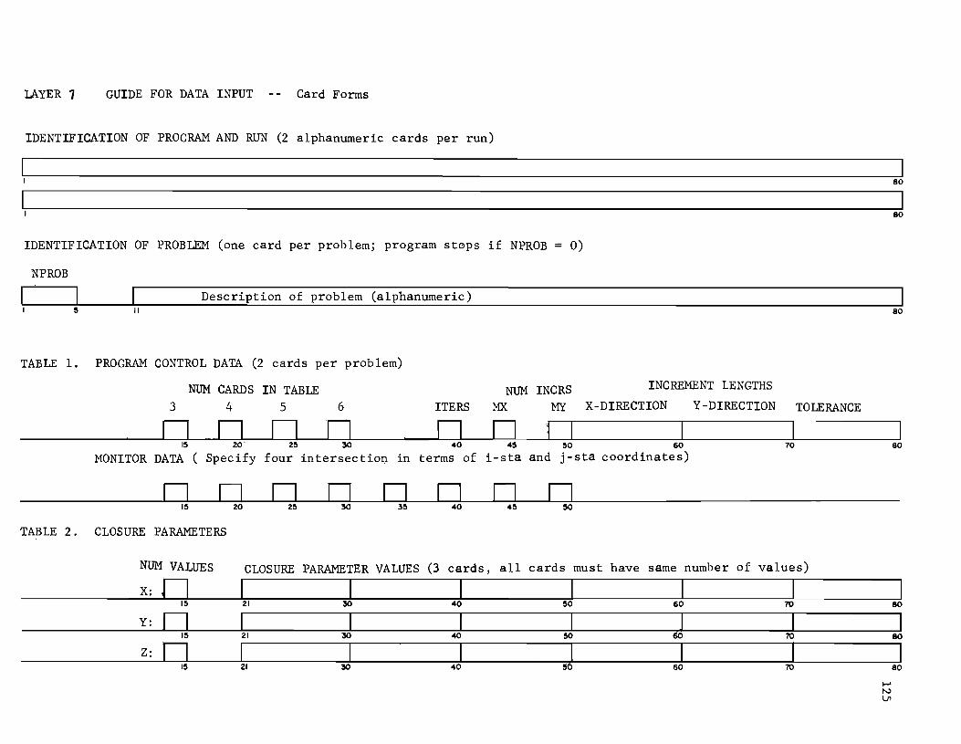
IAYER 1 GUIDE FOR DATA INPUT Card Forms
IDENTIFICATION OF PROGRAM AND RUN (2 alphanumeric cards per run)
80
80
IDENTIFICATION OF PROBLEM (one card per problem; program st0ps if NPROB = 0)
NPROB
Description of problem (alphanumeric) II 80
TABLE 1. PROGRAM CONTROL DATA (2 cards per problem)
NUM CARDS IN TABLE NUM INCRS INCREMENT LENGTHS
3 4 5 6 ITERS MX MY X-DIRECTION Y-DlRECTION TOLERANCE
n n D n n n j 15 20 25 30 40 45 50 60 70 80
MONITOR DATA ( Specify four intersection in terms of i-sta and j-sta coordinates)
n D n n n n n n 15 20 25 30 35 40 45 50
TABLE 2. CLOSURE PARAMETERS
NUM VALUES CLOSURE PARAMETER VALUES (3 cards, all cards must have same number of values)
X: n I I I I I I 15 21 30 40 50 60 70 80
Y: 0 I I I J I 15 21 30 40 50 70
I 80
Z: 0 I I I J I I 15 21 30 40 60 70
I 80
..... N Ln

This page replaces an intentionally blank page in the original --- CTR Library Digitization Team
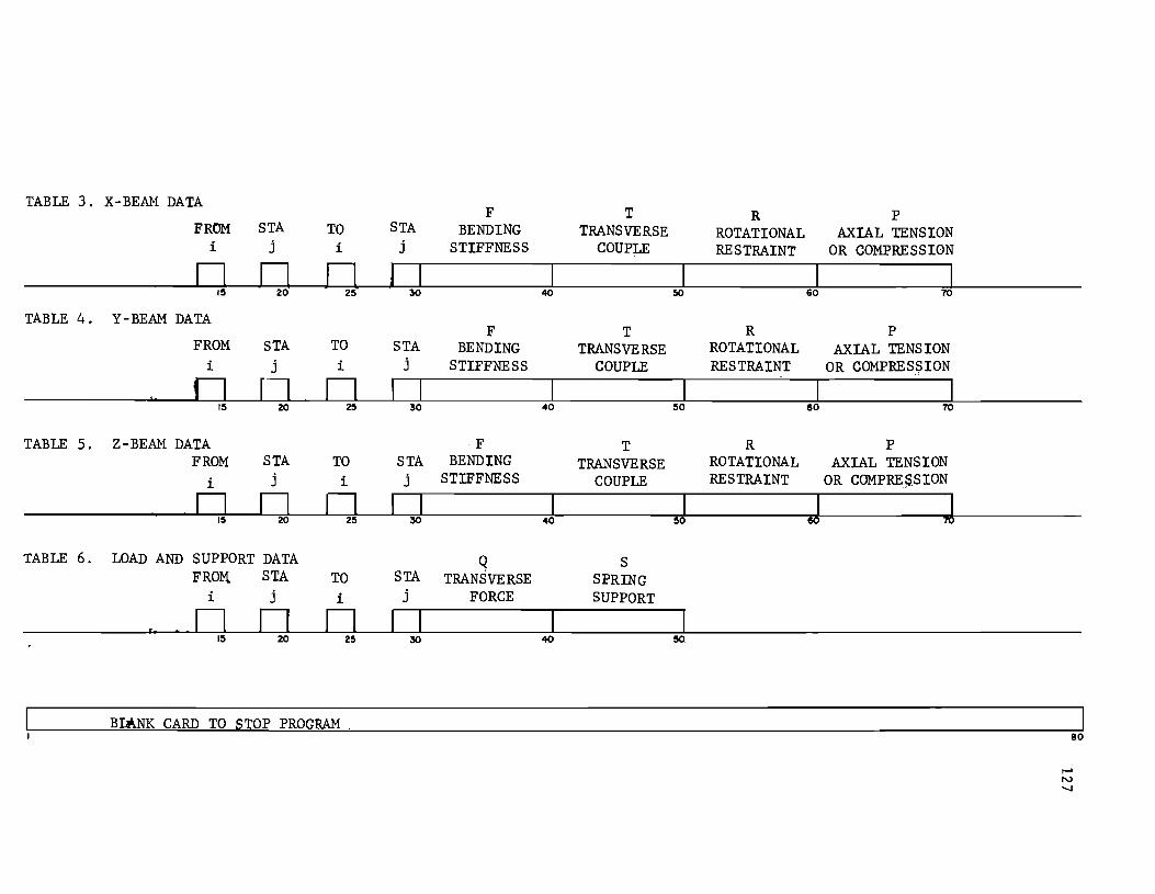
TABLE 3. X-BEAM DATA F T R P
FROM STA TO STA BENDING TRANSVERSE ROTATIONAL AXIAL TENS ION i j i j STIFFNESS COUPLE RESTRAINT OR COMPRESSION
0 0 0 I I I I I IS 20 25 30 40 !!O 60 70
TABLE 4. Y-BEAM DATA F T R P
FROM STA TO STA BENDING TRANSVERSE ROTATIONAL AXIAL TENS ION i j i j STIFFNESS COUPLE RESTRAINT OR COMPRES~ION
0 0 0 I I I IS 20 25 30 40 SO 60 70
TABLE 5. Z-BEAM DATA F T R P FROM STA TO STA BENDING TRANSVERSE ROTATIONAL AXIAL TENSION
i j i j STIFFNESS COUPLE RESTRAINT OR COMPRE~.S ION
0 0 0 I I I J J IS 20 25 30 40 SO
TABLE 6. LOAD AND SUPPORT DATA Q S FROM. STA TO STA TRANSVERSE SPRING
i j i j FORCE SUPPORT
0 D D IS 20 25 30 40 !!O
BUNK CARD TO STOP PROGRAM 80

This page replaces an intentionally blank page in the original --- CTR Library Digitization Team
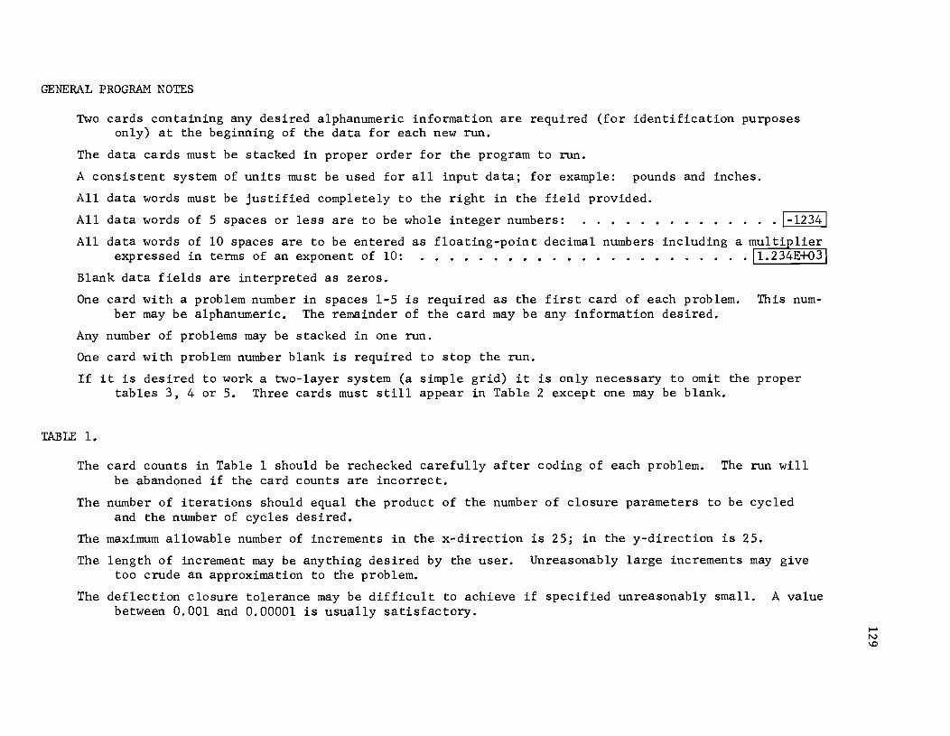
GENERAL PROGRAM NOTES
Two cards containing any desired alphanumeric information are required (for identification purposes only) at the beginning of the data for each new run.
The data cards must be stacked in proper order for the program to run.
A consistent system of units must be used for all input data; for example: pounds and inches.
All data words must be justified completely to the right in the field provided.
All data words of 5 spaces or less are to be whole integer numbers:
All data words of 10 spaces are to be entered expressed in terms of an exponent of 10:
Blank data fields are interpreted as zeros.
1-12341
One card with a problem number in spaces 1-5 is required as the first card of each problem. This number may be alphanumeric. The remainder of the card may be any information desired.
Any number of problems may be stacked in one run.
One card with problem number blank is required to stop the run.
If it is desired to work a two-layer system (a simple grid) it is only necessary to omit the proper tables 3, 4 or 5. Three cards must still appear in Table 2 except one may be blank.
TABLE 1.
The card counts in Table 1 should be rechecked carefully after coding of each problem. The run will be abandoned if the card counts are incorrect.
The number of iterations should equal the product of the number of closure parameters to be cycled and the number of cycles desired.
The maximum allowable number of increments in the x-direction is 25; in the y-direction is 25.
The length of increment may be anything desired by the user. Unreasonably large increments may give too crude an approximation to the problem.
The deflection closure tolerance may be difficult to achieve if specified unreasonably small. A value between 0.001 and 0.00001 is usually satisfactory.

This page replaces an intentionally blank page in the original --- CTR Library Digitization Team
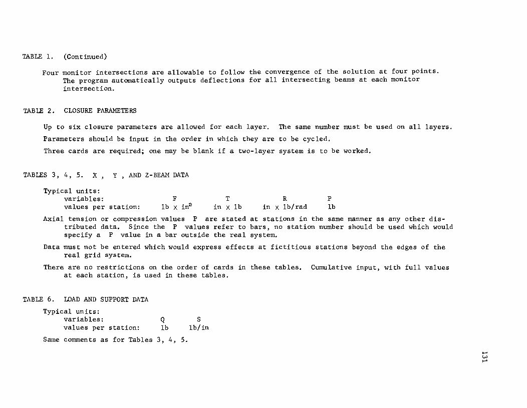
TABLE 1. (Continued)
Four monitor intersections are allowable to follow the convergence of the solution at four points. The program automatically outputs deflections for all intersecting beams at each monitor intersection.
TABLE 2. CLOSURE PARAMETERS
Up to six closure parameters are allowed for each layer. The same number must be used on all layers.
Parameters should be input in the order in which they are to be cycled.
Three cards are required; one may be blank if a two-layer system is to be worked.
TABLES 3, 4, 5. X, Y, AND Z-BEAM DATA
Typical units: variables: values per station:
F lb X in2
T in X lb
R in X lb/rad
P lb
Axial tension or compression values P are stated at stations in the same manner as any other distributed data. Since the P values refer to bars, no station number should be used which would specify a P value in a bar outside the real system.
Data must not be entered which would express effects at fictitious stations beyond the edges of the real grid system.
There are no restrictions on the order of cards in these tables. Cumulative input, with full values at each station, is used in these tables.
TABLE 6. LOAD AND SUPPORT DATA
Typical units: variables: values per station:
Q lb
Same comments as for Tables 3, 4, 5.
S lb/in
APPENDIX 6
DERIVATION OF EQUATIONS FOR THE FINITE-ELEMENT MODEL
OF AN ORTHOTROPIC PLATE-OVER-BEAM SYSTEM

!!!!!!!!!!!!!!!!!!!"#$%!&'()!*)&+',)%!'-!$-.)-.$/-'++0!1+'-2!&'()!$-!.#)!/*$($-'+3!
44!5"6!7$1*'*0!8$($.$9'.$/-!")':!
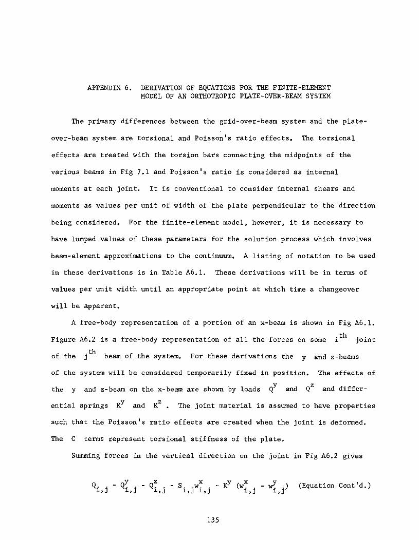
APPENDIX 6. DERIVATION OF EQUATIONS FOR THE FINITE-ELEMENT MODEL OF AN ORTHOTROPIC PLATE-OVER-BEAM SYSTEM
The primary differences between the grid-over-beam system and the p1ate-
over-beam system are torsional and Poisson's ratio effects. The torsional
effects are treated with the torsion bars connecting the midpoints of the
various beams in Fig 7.1 and Poisson's ratio is considered as internal
moments at each joint. It is conventional to consider internal shears and
moments as values per unit of width of the plate perpendicular to the direction
being considered. For the finite-element model, however, it is necessary to
have lumped values of these parameters for the solution process which involves
beam-element approximations to the continuum. A listing of notation to be used
in these derivations is in Table A6.1. These derivations will be in terms of
values per unit width until an appropriate point at which time a changeover
will be apparent.
A free-body representation of a portion of an x-beam is shown in Fig A6.1 •
Figure A6.2 is a free-body representation of all the forces on some . th .. 1. J O1.n t
of the jth beam of the system. For these derivations the y and z-beams
of the system will be considered temporarily fixed in position. The effects of
h d b h b h b 1 d Qy and QZ and d1.·ffer-t e y an z- earn on t e x- earn are s own y oa s
entia1 springs KY and KZ. The joint material is assumed to have properties
such that the Poisson's ratio effects are created when the joint is deformed.
The C terms represent torsional stiffness of the plate.
Summing forces in the vertical direction on the joint in Fig A6.2 gives
y Q •. - Q .• 1.,J 1.,J
Z x _ KY ( x v Q •• - S .. w. . w .. - W' • • ) 1.,J 1.,J 1.,J 1.,J 1.,J (Equation Cont'd.)
135

136
Symbol
D x
F
e
¢
D Y
C C x y pIp t X) Y
S
M I M I x) Y
'Vxy) 'Vyx
V I V I x) Y
M M x Y
V V x y
P P x Y
DID I x) Y
T ,T x Y
R ,R x Y
h
TABLE A6.1. NOTATION FOR PLATE-OVER-BEAM DERIVATIONS
1b-in2 / in.
1b-in2
1b
1b
radians
radians
1b-in2 / rai. lin.
1b/ in.
1b/ in.
in-1b/ in.
1b/in.
in-1b
1b
1b
in-1b
in-lb/rad
in.
1b/in
1b/in
Definition
Plate stiffness/unit width.
Beam stiffness.
Transverse load.
Load resisted by x) y) or z-beam.
Central-difference slope.
Simple-difference slope.
Torsional stiffness/unit width.
Axial force/unit width.
Spring support.
Plate moment/unit width.
Poisson's ratios.
Shear/unit width.
Moment.
Shear.
Axial tension.
Orthotropic stiffness/unit width.
External torque.
External rotational restraint.
Increment length.
Temporary representation in derivations of shear/unit width
Temporary representation in derivations of axial force/unit width
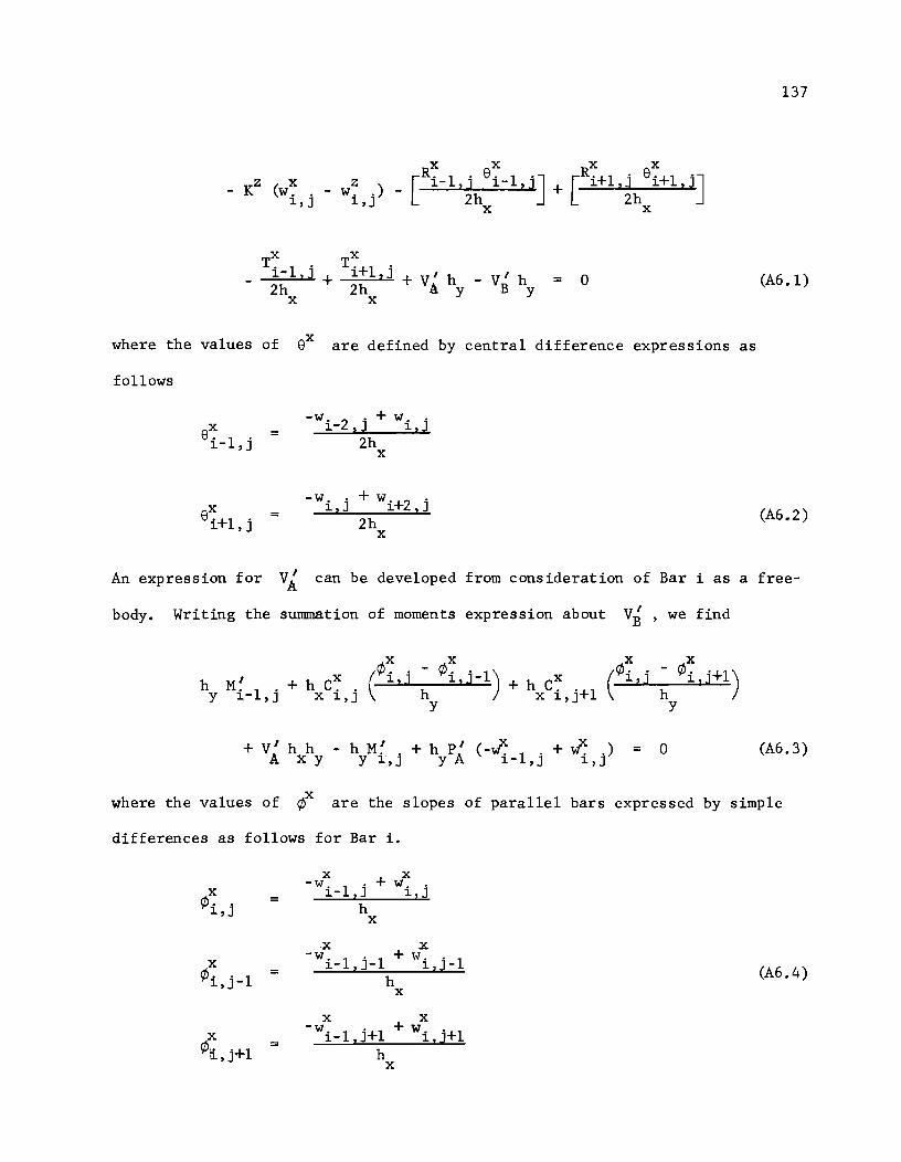
x x x x
[R. 1 . 8. l'J [R·+1 · 8'+1 'J _ KZ (w~ . _ w~ .) _ 1- 'ih 1- ,J + 1 '~h 1 ,J
1,J 1,J X X
X X T. l' T '+1 . 1- ,J + 1 ,J + VI h
2h 2h A y X X
VI h = 0 B Y
where the values of 8x are defined by central difference expressions as
follows
X 8. 1 . 1- , J
X 8'+1 . 1 , J
=
=
-w. 2 . + w .. 1-,J 1,J 2h
X
-Wi,j + wi +2 ,j 2h
X
137
(A6.1)
(A6.2)
An expression for VI A can be developed from consideration of Bar i as a free-
body. Writing the summation of moments expression about V~ , we find
X X X X (¢ .. - ¢ .. 1) (¢ .. ~ ¢i 1 j+1) h I + h eX 1d 1,J- + h eX 1,J
M. 1 . \ y 1- , J X 1, j h X i,j+1 y y
+ VI h h - h M~ + h pI X x) 0 (A6.3) (-w. 1 . + w .. = A X Y Y 1,j yA 1-,J 1,J
where the values of ¢x are the slopes of parallel bars expressed by simple
differences as follows for Bar i.
X X -W i _1 ,j + w ..
X 1,J ¢ .. = 1,J h
X
-x x -w. 1 . 1 + w .. 1
X 1- , J- 1, J- (A6.4) ¢i,j-1 = h X
X X
X -wi -l,j+1 + Wi ,j+1 ¢\i. '+1 = h ,J
X
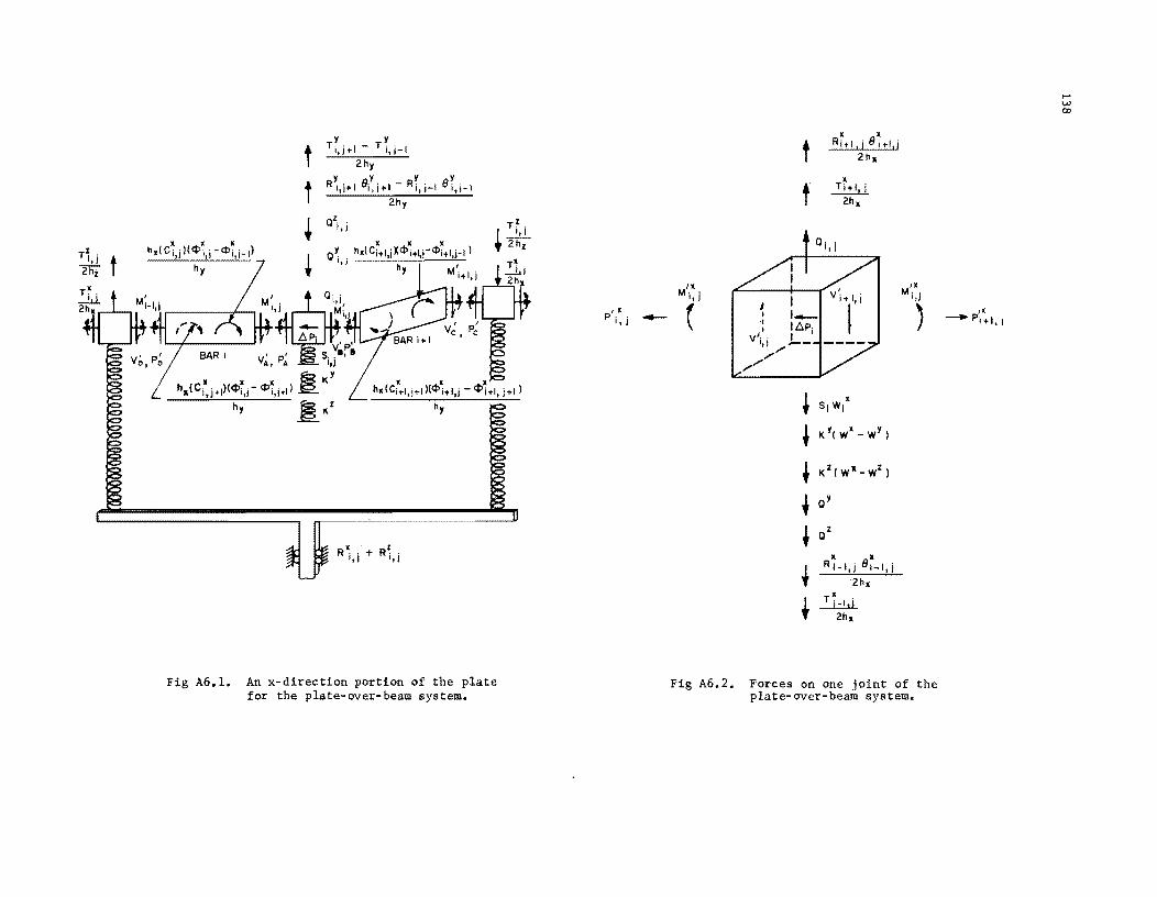
TZ
, t 1.1
2li'i
hxl I)
hy
t t +
*
TY'I-TY'I I,J+ 1,;-2h y
Y e Y Y eY Ri,i+1 i,i+I-Ri,i-1 i,i-
2hy
a\j
x x x QY h.lCi+I,iXcPi+1 ,-cP,+1 i-I)
It j h I. t
Y
TZ
1_"_' t 2hz
L · · · hx(Ci+I,J+Jl(cPi+I,i - ¢i+I, j+l)
R~ . + ',I
hy
Fig A6.l. An x-direction portion of the plate for the plate-aver-beam system.
, . P' ,
" I -
t • ,. T,+I, i
~
ai,i
Ill/x, ,.
P,1, , 1,1 1,1
( , • Si Wi'
• K Y( w' - WY
)
• KZ( wl.-Wz
)
t QY
• a
Z
• x
+ R i-I,i el _ l , i
2hx
• t~
2hx
Fig A6.2. Forces on one joint of the plate-over-beam system.
,..... v.> 00
'x -Pi+I,1
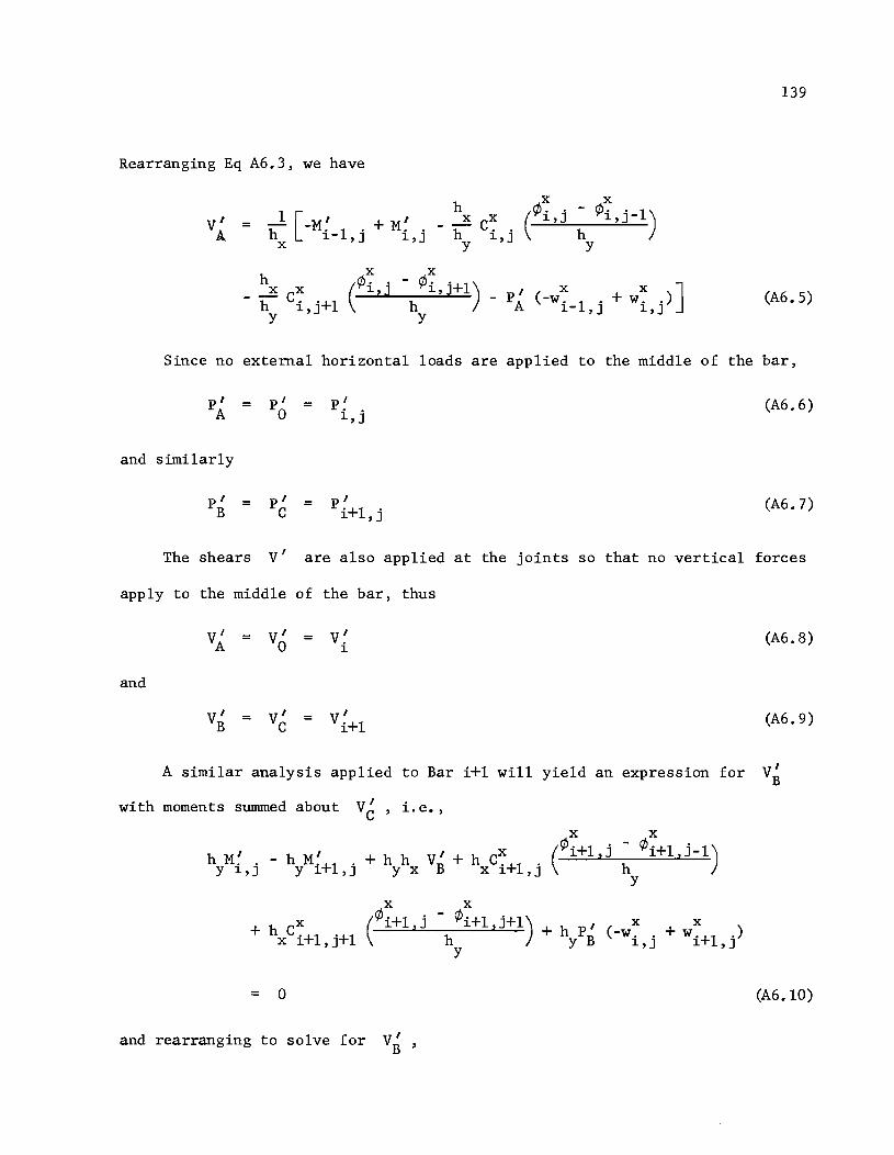
Rearranging Eq A6.3, we have
x h
= hI [-M~ 1 . + M~ . - hX C~ . l-,J 1,J 1,J (
¢ .. 1,J
x Y
h x x
- h Ci,j+l Y
x
(¢ .. 1,]
y
y
- PAl ( -w ~ 1 . + w ~ .) ] l-,J 1,]
139
(A6.5)
Since no external horizontal loads are applied to the middle of the bar,
pI = pI = pI A 0 1,j
(A6.6)
and similarly
pI = pI = pI B C i+l,j
(A6.7)
The shears VI are also applied at the joints so that no vertical forces
apply to the middle of the bar, thus
VI = VI = VI A 0 1
and
VI VI I = = Vi +l B C
A similar analysis applied to Bar i+l will yield an expression for
with moments summed about V~ , i.e.,
x X
I I I x (¢i+l,j h- ¢i+l,j-l) h M. . - h M. +1 . + h h VB + h C. +1 . --=..:...=...l....:<...._---=-.:....=...;<-=--_=_ y 1,J Y 1,J Y x x 1 ,J
= 0
and rearranging to solve for VI B
x
- ¢i+l,j+l) + h pI h y B
Y
Y
x x (-w. . + w.+l .) 1,] 1,J
(A6.8)
(A6.9)
(A6.l0)
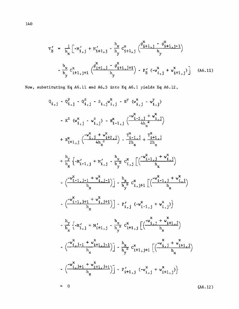
140
Now,
h x x
1 [ I (¢'+1 . ~ ¢i+1';-1) V' I X X 1 .J = h -M •• + Mi +1 . - h Ci +1,j B 1,] ,J X Y Y
h X X
X X (¢i+1,j ~ ¢i+1 ,j+1) - p' X X ...,
- h Ci+1,j+1 (-W .. + W'+l .) J B 1,J 1 , J y Y
substituting Eq A6.11 and A6.5 into Eq A6.1 yields Eq A6.12,
y z X y X v Q. . - Q" " - Q. . - s. .w. . - K (w. . - W'. .) 1,J 1,J 1,J 1,J 1,J 1,J 1,J
X X
(-w. 2 . + w, ') _ KZ ( X z) -x 1-,J 1,J
Wi,j - Wi,j - Ki _1,j 4h 2 X
X (-~,j + W~+2, j) + Ri +1 ,j 4h 2
r TX,
i-1,j + i+1,J 2h 2h
X X X
h h -W:' + w: ' y { I I _ ~ CX [( 1-1,J 1,J) + h -M. 1 ' + M" h 2 i' h X 1-,J 1,J y,J X
(-if. 1 ' 1 + w: '1)- h [(-W: 1 . + w: .) _ 1- ,J-
h 1.J- J _ ~ CX 1-,J 1,J
h 2 i "+1 h X y,J X
X X
_ (-Wi - 1 ,j+1 + Wi ,j+1)l _ pI" X } h I ( -w. 1 . + W ~ ,)
X - 1,J 1-,J 1,J
X X
h J hx X r(-W i ' j +h Wi +1 ,j) - -1. -M I + M I - - C - - -h l i,j i+1,j h a i+1,j
X Y L X
= 0
(A6.1l)
(A6.12)
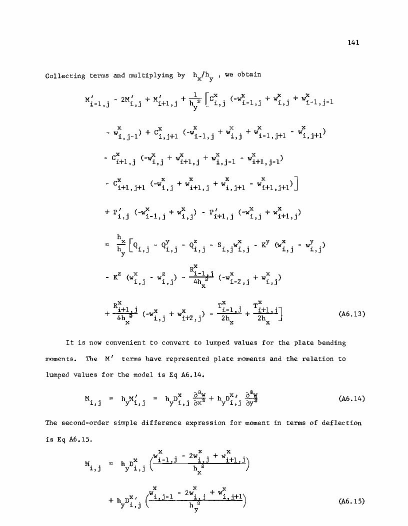
Collecting termS and multiplying by h /h x y we obtain
M I - 2M ~ . + M ~+1 . + h\ [C~ . (-if. 1 . + if. . + if. 1 . 1 i-1,j 1.,J 1.,J 1.,] 1.-,J 1.,J 1.- ,J-Y
- C~+l . (-if. . + if.+1 . + w: . 1 - wX1.·+1,J·_1) 1.,] 1.,] 1.,] 1.,]-
+ P.' . (x + x) P' (x + x ) -w. 1. w.. - . +1 . -w .. w . +1 . 1.,J 1.-,J 1.,J 1.,J 1.,J 1.,J
h = h
X [Q .. 1.,J y
y Q ..
1.,J z
Q .. 1.,] x y x y
S. . w. . - K (w. . - w. .) 1.,J 1.,J 1.,J 1.,J
x R. 1 . z x Z 1.- 1 x x
- K (w. . - w. .) - 4h ~ ( -w. 2 . + w. .) 1.,J 1.,J x 1.-,] 1.,]
Rx. . TX TX
+ 1.+1J J i-1.j + i+1. j } 4h a (-w~. + w~+2 .) - 2h -2=-h;...:;..z. ....
x 1.,] 1.,] X X
141
(A6.13)
It is now convenient to convert to lumped values for the plate bending
moments. The M' terms have represented plate moments and the relation to
lumped values for the model is Eq A6.14.
M. . = h M~ . 1.,] Y 1.,] X (Jaw x (JsW
h D ... ~ + h D.'. -;:::-2 Y 1.,J oX Y 1.,J oy (A6.14)
The second-order simple difference expression for moment in terms of deflection
is Eq A6.15.
M .. 1.,J =
+ h D~ I. Y 1.,]
x
1..J-(
w .. 1 x
- 2w .. 1. z J h 2
Y
(A6.15)
142
XI I In Eqs A6.l4 and A6.l5, the D4 • represents the Poisson s ratio effect +,J
on the stiffness. D~/. is defined by Eq A6.l6. This definition will be shown ~,J
in Appendix 7.
X = v D .. It
Y ~,J (A6.l6)
It is also convenient now to substitute a lumped value of axial tension as
defined by EqA6.l7
P~. = h P~ . ~,J Y ~,J
(A6.17)
Writing Eq A6.l5 at each of three successive stations and substituting
these and Eq A6.l7 into Eq A6.l3 yields Eq A6.l8 after clearing equations by
multiplying by a factor of
h 2
~ [D~_l,j (W~_2,j - 2w~_1,j + W~,j) - 2D~,j (W~_l,j - 2W~,j
- 2D~ I. (w'I. . 1 - 2wY. , + wY. '+1) ~,J ~,J- ~,J ~,J
+ [c terms from Eq A6.l3] + h P~ . (-w~ 1 . + w~ ,) Y ~,J ~-,J ~,J
X X X - h P'+l ' (-w .. + w'+l .) Y ~,J ~,J 1: ,J
= h h [Q .. - QY. , y x ~,J ~,J
Q~ . - S. .w~ . - KY (w~ , - w'I. .) ~,J ~,J~,J ~']~,J
(Equation Cont'd.)
143
x R. 1 .
KZ x w~ .) ] - h 1.- z] X X - (w .. - (-w. 2 • + w . .)
1.,J 1.,J Y 4h 1.- , J 1.,J x
x hy
+h Ri +l , j x x x x (A6.l8) (-w .. + w'+2 .) - - (T. 1 . - T'+l .) y 4h 1.,J 1. , J 2 1. - , J 1. , J x
Now, rearranging Eq A6.l8 into ,form for ~ five-diagonal matrix solution results
in Eq A6.l9.
h 2 h x
w. 2 • 1. - , J [y x X-Z-J ~ Di _l J' - Ri _l J' 4h . x ' , x
h 2
+ X [2 Y (x + DX. • ) CX CX h pX l Wi_l,j _- h
x2 Di_l,j 1.,J - i,j - i,j+l - y i,jJ
x x x x + C '+1 . + C '+1 '+1 + h (P. . + P '+1 .) 1.,J 1.,J Y 1.,J 1.,J
+~ (R~_l J' + R~+l'J') + h h (S .. + KY + KZ)]
x' x Y 1.,J
~2 + w~+l . [-2 h a (D~ . + D~+l .)- C~+l . - C~+l '+1 - h P~+l .J 1. ,J 1.,J 1.,J 1.,J 1.,J Y 1. ,J x
x x x x x x + C .. (w. 1 . 1 - w .. 1) + C. '+1 (w1.·-l,J·+l - w. '+1) 1.,J 1.- ,J- 1.,J- 1.,J 1.,J
x x x x x x ~ Ci+l,j (wi,j_l - wi+l,j-l) - Ci+l,j+l (wi,j+l - wi+l,j+l)
+ D~~l,j (W~_l,j_l - 2W~_1,j + ~-l,j+l) (Equation Cont'd.)
144
= h h (Q •• - QY. . xy ~,J ~,j
z y y z z ) Q •. + K w .• + K w •• ~,J ~,J ~,J
(A6.l9)
and
All terms on the left side of Eq A6.19, with the exception of the
x K terms, represent the load Q .. ~,j
as shown previously in Eq 7.4.
S .. ~,J
A
similar derivation for each of the y and z-beams would yield Eqs A6.20 and
A6.2l whose left sides represent respectively the y Q. . ~,J
z and Q, j
~, terms. No
torsion nor Poisson's ratio terms appear in Eq A6.2l since beam torsion is not
considered for the z-beam.
-2h 2
+ ~ J'-l [ h i (DY. , 1 + DY. ,) - cY. , - cY.+l . - h py' .J L, Y ~,J- ~,J ~,J ~ ,J x ~,J
h 2 Y rx y y y
+ w, , Lb'T (D i J' -1 + 4D. . + D i, j+l) ~,J y' ~,J
h + 4h
x (RY. . 1 + RY. '+1) + h h (S. ,+ K
X + KZ)J
~,J- ~,J Y x ~,J Y
-2h 2
+ ~,j+l [hy~ (DLj + DLj+l) - C~,j+l - C~+l,j+l - hxpLj+1J
h :a h _ y [XX x y J
+ W'i,j+2 h 2 Di ,j+l - 4h Ri,j+l y y
(Equation Cont'd.)
145
h + 2
x (~ . 1 - ~ '+1) + C~ . (WI. 1 . 1 - wY. 1 .) ~,J- ~,J ~,J ~- ,J- ~- ,J
x ~v I X X X + W-l+1 ,J'-1) - 2V" . • (w. 1 ' - 2w .. + w'+l .) ... ~,J ~- ,J ~,J 1:,J
x x z Z x z) = h h (Q • • + K w •• + K w. j - Q. j - Q •• x Y ~,J ~,J ~, ~, ~,J
(A6.20)
[ h J Z z z z
w. 2 . F. 1 ' - --4 R. 1 . ~- ,J ~-,J ~- ,J
+ w: 1 . [-2 (F: 1 . + F: .) - h 2 P: .J ~- ,J ~- ,J ~,J z ~,J
+ W: . [F: 1 . + 4F: , + F:+1 . + h 2 (P: . + P:+1 ,) ~,J ~-,J ~,J 1: ,J Z ~,J ~ ,J
h + 4
Z (R: 1 ' + R:+1 ,) + s .. h 3l + h 3 (KY + KX)
~- ,J 1:, J 1:, J Z _ Z
Z [-2
Z Z _ h a P~+l,jJ + w'+l . (F .. + F '+1 .) ~ ,J ~,J 1: ,J Z
h h2 Z [ Z Z Z ]
z (Tz
TZ ) + w'+2 ' F '+1 . - "'4 R'+l . + 2 . 1 ' '+1 . ~ ,J 1:,J ~ ,J ~- ,J ~ ,J
(A6.21)
Eqs A6.19, A6.20 and A6.21 can be written in symbolic form as Eqs A6.22
where all terms with superscripts represent particular layers of the system.
Equation A6.22 is arranged in a convenient manner for iterative solution.
146
QX+s X..l.Kyx+KzX = .w.. w. w. 1 1 1 1
(A6.22)
Eqs A6.19, A6.20 and A6.21 are in the form necessary for the use of the
quidiagonal matrix solution process. They can be represented as Eq A6.23 in
the same manner that Eq Al.17 is represented.
= f o
(A6.23)
APPENDIX 7
DEVELOPMENT OF CONSTANTS FOR ORTHOTROPIC PLATE

!!!!!!!!!!!!!!!!!!!"#$%!&'()!*)&+',)%!'-!$-.)-.$/-'++0!1+'-2!&'()!$-!.#)!/*$($-'+3!
44!5"6!7$1*'*0!8$($.$9'.$/-!")':!
APPENDIX 7. DEVELOPMENT OF CONSTANTS FOR ORTHOTROPIC PLATE
An orthotropic plate is a plate which may have different material
properties in any of its orthogonal directions. The usual example of an
orthotropic material is plywood. The independent constants for an ortho-
tropic material will be discussed in this section.
Consider Fig A7.1a, a plane element of some orthotropic material. If
some stress (J x
is applied along with a (J = 0 , there will be a deformation y
of the element to the deformed shape shown in Fig A7.1a corresponding to a
strain € and € xx yx
The first subscript indicates stress direction and
the second indicates strain direction.
Equation A7.1 is Hooke's law as a stress-strain relation. The conven-
tiona1 definition for Poisson's ratio is the ratio of lateral strain to
longitudinal strain, or Eq A7.2.
(J
E x =
X € xx
-€
\) = ..2SY xy € xx
A similar stress applied to the Fig A7.1b, but with
and (J = 0 , would lead to Eqs A7.3 and A7.4. x
(J
E = ...:L y € yy
-€
\) = ~ yx € yy
and
149
(A7.1)
(A7.2)
€ having a value y
(A7.3)
(A7.4)
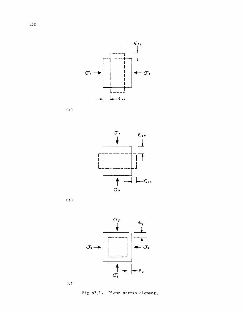
150
I I I I I I I I I I I ! I
( 0 )
r'~------- -11 I I I I - ----- -- f--
( b)
f ~()x
-----1 I I I I I I L ____ J
(c)
Fig A7.l. Plane stress element.
151
E: = -v E: yx yx yy (A7.5)
a E: = -v ...:t. yx yxE
y (A7.6)
and similarly from Eqs A7.2 and A7.l
-v E: = -Ei. xy E ax
x (A7 .7)
If two stress components were applied simultaneously (Fig A7.lc) then by
superposition the components of strain in the respective x and y-directions
would be expressed as Eqs A7.8 and A7.9
= E: + E: xx yx (A7.8)
E: + E: yy xy (A7.9)
Then, substituting Eqs A7.l, A7.3, A7.6, and A7.7 into Eqs A7.8 and A7.9,
it can be shown that
and
E: X
= ax a
-v ...:t. E yx E
x Y
a a E: Y
-v ~ + ...:t. xy E E
x Y
Equation A7.l0 can be rearranged to arrive at Eq A7.l2,
a x
(A7.l0)
(A7.11)
(A7.l2)
which in turn can be substituted in Eq A7.11 to obtain an expression for the
y-strain component, Eq A7.13
= -~xy (E:x
+ V ~) E + ~ E yxE x E
x Y Y (A7.13)
152
which in turn rearranged yields Eq A7.l4 which is a function of three material
constants.
a y =
E Y
1 - v v xy yx (€ + V €) y xy x
A similar expression, Eq A7.l5 can be developed for the x-stress
component.
a x =
E x
1 - v v xy yx (e + v €)
X yx Y
(A7.l4)
(A7.l5)
Under the usual assumptions of small deflection theory, the strain may be
expressed in the forms of Eq A7.l6 (Ref 28, p 364).
(;2'w e = z
ox2 X
02W (A7.l6) € = z~ Y
The external moments M and M can be defined in terms of normal x y
stresses (Ref 28, p 365) as Eq A7.l7 for
M dy x
t/2
= J -t /
2
a zdydz x
where t is the plate thickness.
M x
Substituting Eq A7.l5 and A7.l6 into Eq A7.l7, we have
M x
and performing the integrations results in Eq A7.l9.
(A7.l7)
(A7.l8)
(A7.l9)
It now is convenient to define several new terms in notation similar to
153
Timoshenko and Woinowsky-Krieger (Ref 28).
E E' x (A7.20) = x 1 - \) \)
xy yx
E E' = ::i (A7.21) y 1 - \) \)
xy yx
E ' t 3
D x (A7.22) = x 12
E f t 3
D ~ (A7.23) y 12
D' = \) D = \) D yx :x xy y
(A7.24)
Equation A7.24 implies that there is a relationship between the two
Poisson's constants. This relationship is stated in Eq A7.2S. The validity
of Eq A7.2S is proved by Hearmon (Ref 12), and similar results can be found in
Crandall and Dahl (Ref 7) as well as Dow, Libove, and Hubka (Ref 8).
\) yx
E = \) J.
xy E x
(A7.2S)
Thus, the orthotropic plate is seen to have two values of Poisson's ratio
and two stiffness constants.
Torsional Stiffness
The values of stiffness for the torsion bars in Fig A7.2 are clear for
isotropic conditions. For orthotropic conditions, howevever, there appears to
be considerable debate about the proper manner to express the shear modulus G.
The twisting moments on each face of a plate segment must be such that
equilibrium exists at segment corners, or Eq A7.26 must be satisfied (Ref 28).
M =-M yx xy (A7.26)
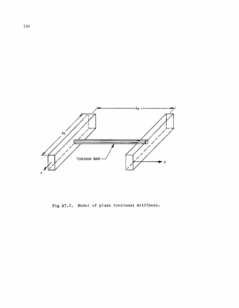
154
~~---------------hy----------~~
TORSION BAR )000'--7'------; .... y
x
Fig A7.2. Model of plate torsional stiffness.
Furthermore, for isotropic conditions Eq A7.27 relates the twisting
moments to the shearing modulus and the plate thickness.
M = yx (i3w OXQY =
02W D (1 - \}) QXQY
155
(A7.27)
The twisting moments have units of in-lb/in. of plate width. Either form
of Eq A7.27 is acceptable for the isotropic plate.
If eX is the resistance to twisting about the x-axis and eY is the
resistance to twisting about the y-axis, then Eq A7.28 and A7.29 relate the
stiffnesses to the twisting moments.
M x oaw (A7.28) = e oYOX yx
-M = eY rfw (A7.29) xy oXoY
Equating Eqs A7.28 and A7.29, and noting Eq A7.27, it is apparent that
for the isotropic plate.
Gt3
6 (A7.30)
For the isotropic plate the shear modulus G is defined by Eq A7.3l.
G E
(A7.31) 2 (1 + \})
For the orthotropic plate the shear modulus has been shown to take the
form of Eq A7.32 (Ref 19).
E E G =
x y (A7.32) E (1 + \) ) +E (1 + \) )
y xy x yx
Equation A7.32 is approximate but can be used with reasonable reliability.
Otherwise the shear modulus must be determined from an independent test.

!!!!!!!!!!!!!!!!!!!"#$%!&'()!*)&+',)%!'-!$-.)-.$/-'++0!1+'-2!&'()!$-!.#)!/*$($-'+3!
44!5"6!7$1*'*0!8$($.$9'.$/-!")':!
APPENDIX 8
SELECTION OF CLOSURE PARAMETERS FOR PLATES

!!!!!!!!!!!!!!!!!!!"#$%!&'()!*)&+',)%!'-!$-.)-.$/-'++0!1+'-2!&'()!$-!.#)!/*$($-'+3!
44!5"6!7$1*'*0!8$($.$9'.$/-!")':!
APPENDIX B. SELECTION OF CLOSURE PARAMETERS FOR PlATES
The concepts discussed in Chapter 4 and Appendix 2 for simply-connected
gridworks will be extended to the solution of an orthotropic-plate-over-beam
layered system. The selection of closure parameters for the beams is identical
to the method in Chapter 4. The following developments for eigenvalues of
plates are primarily those of Salani (Ref 26).
Eigenvalue for Plate
The finite-difference form for either the horizontal matrix operator or
the vertical matrix operator of the plate equation can be written as Eq AB.l.
= A w. n 1.
(AB.l)
If Eq AB.2 is assumed to represent the deflected shape of the plate, then
four additional equations may be written, Eqs AB.3.
w. = sin is 1. n (A8. 2)
w. 2 = sin (i-2)S = sin (is 2S ) 1.- n n n
wi
_l = sin (i-l)(3 = sin (i(3 (3n) n n
(AB.3) wi +l = sin (i+l) S = sin (i(3 + S ) n n n
wi +2 = sin (i+2) (3 = sin (i(3 + 2(3 ) n n n
Using an appropriate trigonometric identity, Eqs AB.3 can be converted to
Eq AB.4.
= sin (is ) cos (2S ) - cos (is) sin (2 (3 ) n n n n
= sin (is ) cos (S ) - cos (i(3 ) sin (Sn) n n n
159
160
= (A8.4)
wi +2 = sin (is) cos (2S ) + cos (is) sin (2S ) n n n n
Then, by substituting Eq A8.4 and Eq A8.2 into Eq A8.l and simplifying, we have
= 2 cos 2S - 12 cos ~ + 10 n n (A8.5)
D
Noting that cos 2S = 2 cos2 S - 1 results in the following change in n n
Eq A8.5
= 4 cos2 S - 12 cos ~ + 8 n . n
which, after rearranging, becomes
= 4 (1 - cos S ) (2 - cos S ) n n D
Boundary conditions show that
or that
sin M~ = 0 n
Sn = .!!II M
(A8.6)
(A8.7)
(A8.8)
(A8.9)
where n is the number of the eigenvalue and ranges from 1 to M-1. M is
the number of increments into which the strip of the plate is divided. The
final expression for the eigenvalues of the line-element strips of plate is
Eq A8.10.
= nIT nTT 4 (1 - cos -) (2 - cos -) M M (A8.10)
D
Fictitious Springs
The closure spring for a plate has the form
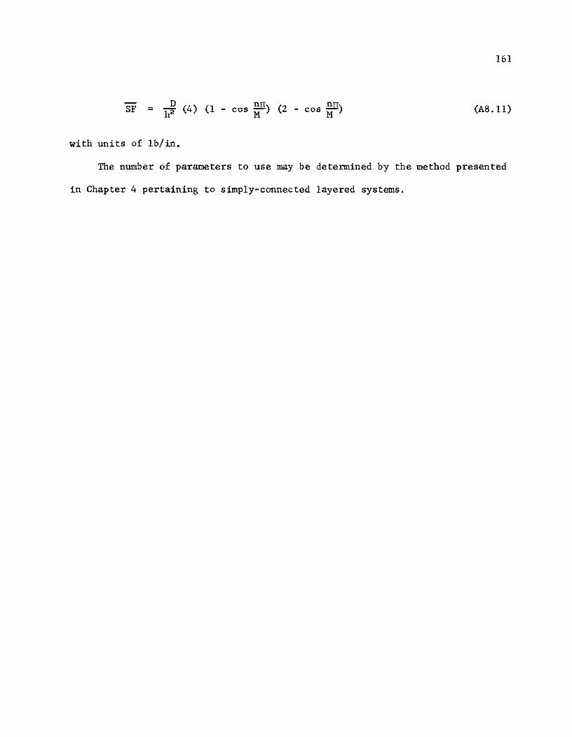
161
SF D nn nn = :a (4) (1 - cos --) (2 - cos --) h M M (AS. 11)
with units of lb/in.
The number of parameters to use may be determined by the method presented
in Chapter 4 pertaining to simply-connected layered systems.

!!!!!!!!!!!!!!!!!!!"#$%!&'()!*)&+',)%!'-!$-.)-.$/-'++0!1+'-2!&'()!$-!.#)!/*$($-'+3!
44!5"6!7$1*'*0!8$($.$9'.$/-!")':!

APPENDIX 9
FLOW DIAGRAM FOR PROGRAM IAYER 8

!!!!!!!!!!!!!!!!!!!"#$%!&'()!*)&+',)%!'-!$-.)-.$/-'++0!1+'-2!&'()!$-!.#)!/*$($-'+3!
44!5"6!7$1*'*0!8$($.$9'.$/-!")':!
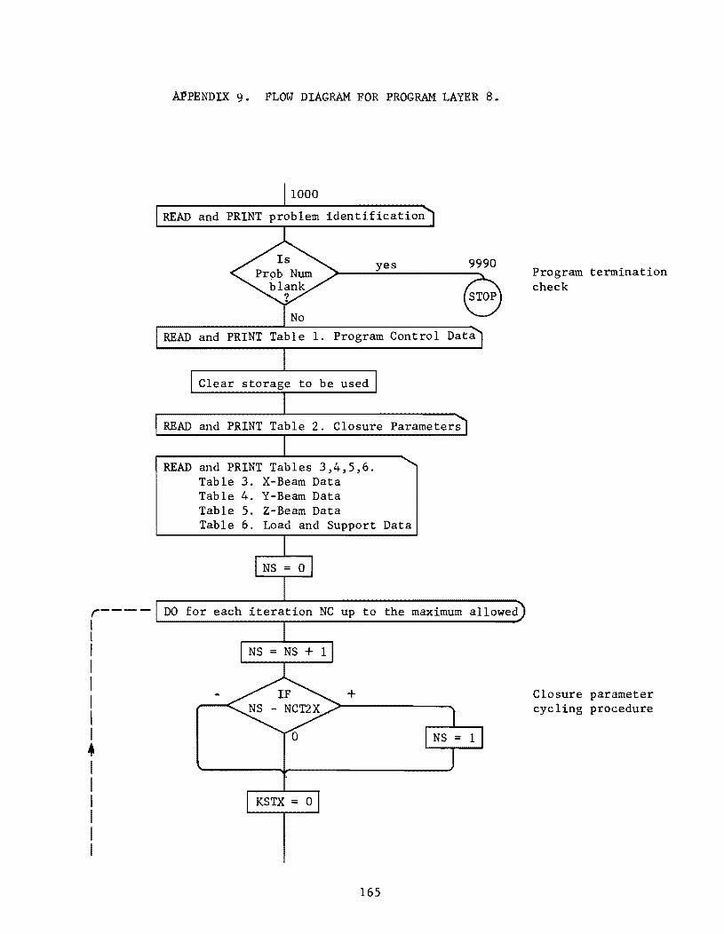
r----I I I I I I I I • I I I I I I
APPENDIX 9. FLOW DIAGRAM FOR PROGRAM LAYER 8.
1000
READ and PRINT problem identification
yes 9990
READ and PRINT Table 1. Program Control Data
Clear storage to be used
READ and PRINT Table 2. Closure Parameters
READ and PRINT Tables 3,4,5,6. Table 3. X-Beam Data Table 4. Y-Beam Data Table 5. Z-Beam Data Table 6. Load and Support Data
DO for each iteration NC up to the maximum allowed
+
KSTX = 0
165
Program termination check
Closure parameter cycling procedure
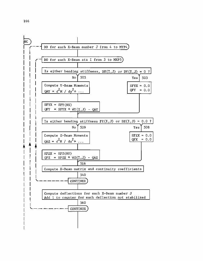
166
• • • I I I I I I I I I I I \.._ I I I I I \.._-
I DO for each X-Beam number J from 4 to MYP4
DO for each X-Beam sta I from 3 to MXP5)
Is either bending stiffness, DX(I, J) or DY(I,J) = 0 ?
No y 505 Yes 503
Compute Y-Beam Moments SFYX = 0.0 2 2 QAY = d M / dy· + ... QFY = 0.0
SFYX = SFY(NS) QFY = SFYX * WY (I , J) - QAY
Is either bending stiffness FZ(I,J) or DX(I,J) = 0.0 ?
No y 509 Yes 1508
Compute Z-Beam Moments SFZX = 0.0 2 2
QAZ = d M / dz + ... QFX = 0.0
SFZX = SFZ(NS) QFZ = SFZX * WZ(I, J) - QAZ
516
Compute X-Beam matrix and continuity coefficients I 540
- ---- -I CONTINUE)
Compute deflections for each X-Beam number J Add 1 to counter for each deflection not stabilized
560
----- CONTINUE)
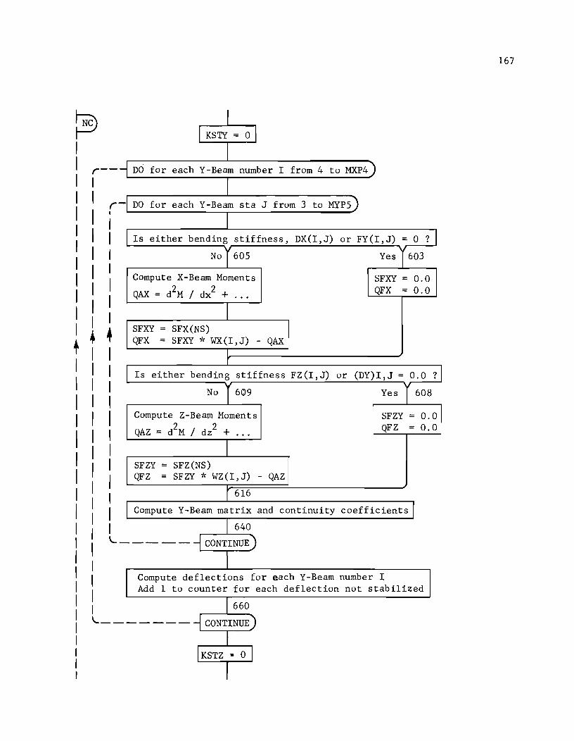
r--I I r I ' I I I I I I I
! + +
-
I I KSTI = 0 J
I DO for each Y-Beam number I from 4 to MXP4
I DO for each Y-Beam sta J from 3 to MYPS)
I Is either bending stiffness, DX(I, J) or FY(I,J) = 0 ?
No y 60S Yes y 603
Compute X-Beam Moments SFXY = 0.0
QAX = d2M / dx2 + QFX = 0.0 ... I
SFXY = SFX(NS) QFX = SFXY * WX(I, J) - QAX
I r
Is either bending stiffness FZ (I, J) or (DY)I,J = 0.0 ?J No 1609 Yes y 608
Compute Z-Beam Moments SFZY = 0.0
QAZ = d2M / dz2 + QFZ = 0.0 ... I
SFZY = SFZ(NS) QFZ = SF zy ·k WZ (I , J) - QAZ
r 616
Compute Y-Beam matrix and continuity coefficients I I 640
------- CONTINUE)
I Compute deflections for each Y-Beam number I Add 1 to counter for each deflection not stabilized
I 660 \...._------ CONTINUE
I I KSTZ • 0 I
I
167
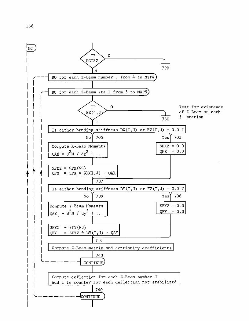
168
r--I I I I I I I I I I I
t +
r I I I I I I I I I I + I I I I I I I I I I
-
IF 0 NCT2Z
- + 790
DO for each Z-Beam number J from 4 to MYP4
I DO for each Z-Beam sta I from 3 to MXPS)
IF 0 Tes FZ(4,J of
760 j
- + Is either bending stiffness DX(I,J) or FZ(I,J) = 0.0 ?
No 170S Yesl703
Compute X-Beam Moments SFXZ = 0.0
QAX = d2M / dx2 + QFZ = 0.0 ...
I SFXZ = SFX(NS) QFX = SFX 'k WX(I,J) - QAX
r 707
Is either bending stiffness DY(I,J) or FZ(I,J) = 0.0 ?
No 1709 YeSl708
Compute Y-Beam Moments SFYZ = 0.0
QAY = d2M / d/ + OFY = 0.0 ... I
SFYZ = SFY(NS) QFY = SFYZ -J~ WY(l,J) - QAY
r 716
Compute Z-Beam matrix and continuity coefficientsl
I 740 I '-------- CONTINUE)
I Compute deflection for each Z-BeaQ number J Add 1 to counter for each deflection not stabilized
I 760
'---- - - - -- -~ONTINUE )
I
t for existence Z Beam at each station
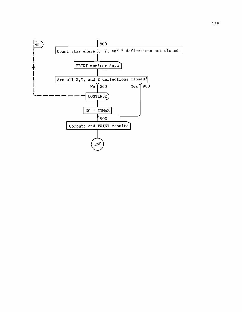
~ I I + I I I I
800
Count stas where X, Y, and Z deflections not closed
PRINT monitor data
Are all X,Y, and Z deflections closed?
Yes 900
"---------
Compute and PRINT results
169

!!!!!!!!!!!!!!!!!!!"#$%!&'()!*)&+',)%!'-!$-.)-.$/-'++0!1+'-2!&'()!$-!.#)!/*$($-'+3!
44!5"6!7$1*'*0!8$($.$9'.$/-!")':!
APPENDIX 10
NOTATION AND LISTING OF PROGRAM LAYER 8

!!!!!!!!!!!!!!!!!!!"#$%!&'()!*)&+',)%!'-!$-.)-.$/-'++0!1+'-2!&'()!$-!.#)!/*$($-'+3!
44!5"6!7$1*'*0!8$($.$9'.$/-!")':!
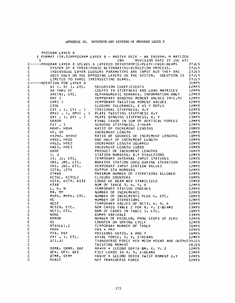
APPENDIX 10. NOTATION AND LISTING OF PROGRAM LAYER 8
PROGRAM LAYER 8 1 FORMAT (5X.52HPROGRAM LAYER 8 - MASTER DECK WB INGRAM. H MATLOCK
1 28H REVISION DATE 27 JUL 651 C-----PROGRAM LAYER 8 SOLVES A LAYERED ORTHOTROPIC-PLATE-OVER-BEAMS 27JL5 C SYSTEM BY A THREE-PHASE ALTERNATING-DIRECTION PROCESS. 27JL5 C INDIVIDUAL LAYER CLOSURE PARAMETERS ARE INPUT BUT THEY ARE 27JL5 C USED ONLY ON THE OPPOSING LAYERS IN THE SYSTEM. SOLUTION IS 27JL5 C LIMITED TO THREE: INTERSECTING BEAMS. 27JL5 C-----NOTATION FOR LAYER 8 31MY5 C AI I. BI I. HC. RECURSION COEFFICIENTS 12MY5 C AA THRU FF COEFFS IN STIFFNESS AND LOAD MATRICES 12MY5 C ANIINI. ETC. ALPHANUME~IC REMARKS. INFORMATION ONLY l2MY5 C BMI ) TE~PORARY BENDING MOMENT VALUES IN=l.9) l2MY5 C CMXI ) TEMPORARY TWISTING MOMENT VALUES l2MV5 C CTOL CLOSURE TULERANCE, X VS V DEFLS l2MV5 C CXI • J. CYI • TORSIONAL STIFFNESS. X.Y 12MY5 C DPXI • I. DPYI PLATE TWISTING STIFFNESS X.Y l2MY5 C DXI • ). DYI PLATE BENDING STIFFNESS, X, Y l3MY5 C ERROR FINAL ERROR IN SUM OF VERTICAL FORCES 12MY5 C FZI • ) BENDING STIFFNESS, Z-BEAM l2MY5 C HDHY, HDHX RATIO OF INCREMENT LENGTHS lOMY5 C HX, HY INCREMENT LENGTH 12MY5 C HX2H2. HY2H2 RATIO OF SQUARES OF INCREMENT LENGTHS lOMY5 C HXD2. HYD2 ONE HALF OF INCREMENT LENGTH 10MY5 C HXE2. HYE2 INCREMENT LENGTH SQUARED lOMY5 C HXE3. HYE3 INCREMENT LENGTH CUBED lOMY5 C HXHY PRODUCT OF INCREMENT LENGTHS lOMY5 C I. J STATION NUMBERS. X.Y DIRECTIONS 12MY5 C II. J1. ETC. TEMPORARY INTERNAL INPUT STATIONS 12MY5 C IM1. JMl. ETC. MONITOR STATION USED DURING ITERATION l2MY5 C INl. JNl. ETC. TEMPORARY INPUT STATION VALUES l2MY5 C ISTA. JSTA OUTPUT STA NUMBERS l2MY5 C ITMAX MAXIMUM NUMBER OF ITERATIONS ALLOWED l2MY5 C KCTOL. KCTOLZ CLOSURE COUNTERS lOMY5 C KSTX. KSTY. KSTZ COUNT OF BEAM NOT STABILIZED lOMY5 C KTAB NUM OF TABLE 3. 4, 5. 6 12,",Y5 C L. K. N TEMPORARY STATION INDEXES 12MY5 C MX. MY NUMBER OF INCRf::MENTS 12MY5 C MXP4. MYP4, ETC. NUMBER OF INCREMENTS PLUS 4. ETC. lOMY5 C NC NUMBER OF ITERATIONS 12MY5 C NCDT TEMPORARY VALUES OF NCT3. 4. 5. b 12MV5 C NCT2X. ETC. NUM CARDS TABLE 2 FOR X. Y. Z-BEAMS 13MY5 C NCT3. ETC. NUM OF CARDS IN TABLE 3. ETC. 10MY5 C NONE DUMMY VAR IABLE 13MY5 C NPROB NUMBER OF PROBLEM. PROG STOPS IF ZERO 12MY5 C NS COUNTER ON SPRING CYCLE 12MY5 C NTABLEl.2 TEMPORARY NUMBER OF TABLE 31MY5 C PRPR PRX * PRY 12MY5 C PRX. PRY POISSONS RATIO. X AND Y lOMY5 C PXI • ). ETC. AXIAL FORCE, X. Y. Z-BEAMS 12MY5 C QII.J) TRANSVERSE FORCE PER MESH POINT AND OUTPUT28JE5 C TWISTING MOMENT 28JE5 C QBMX. QBMY. QAZ HX*HY * SECOND DERIV BM. X. Y. Z 12MY5 C QFX. QFY, QFZ FICT LOADS IN X, Y. Z-BEAMS 13MY5 C QTMX. QTMY HX*HY * SECOND DERIV TWIST MOMENT X.Y 12MY5 C REACT NET TRANSVERSE FORCE 12MY5
173
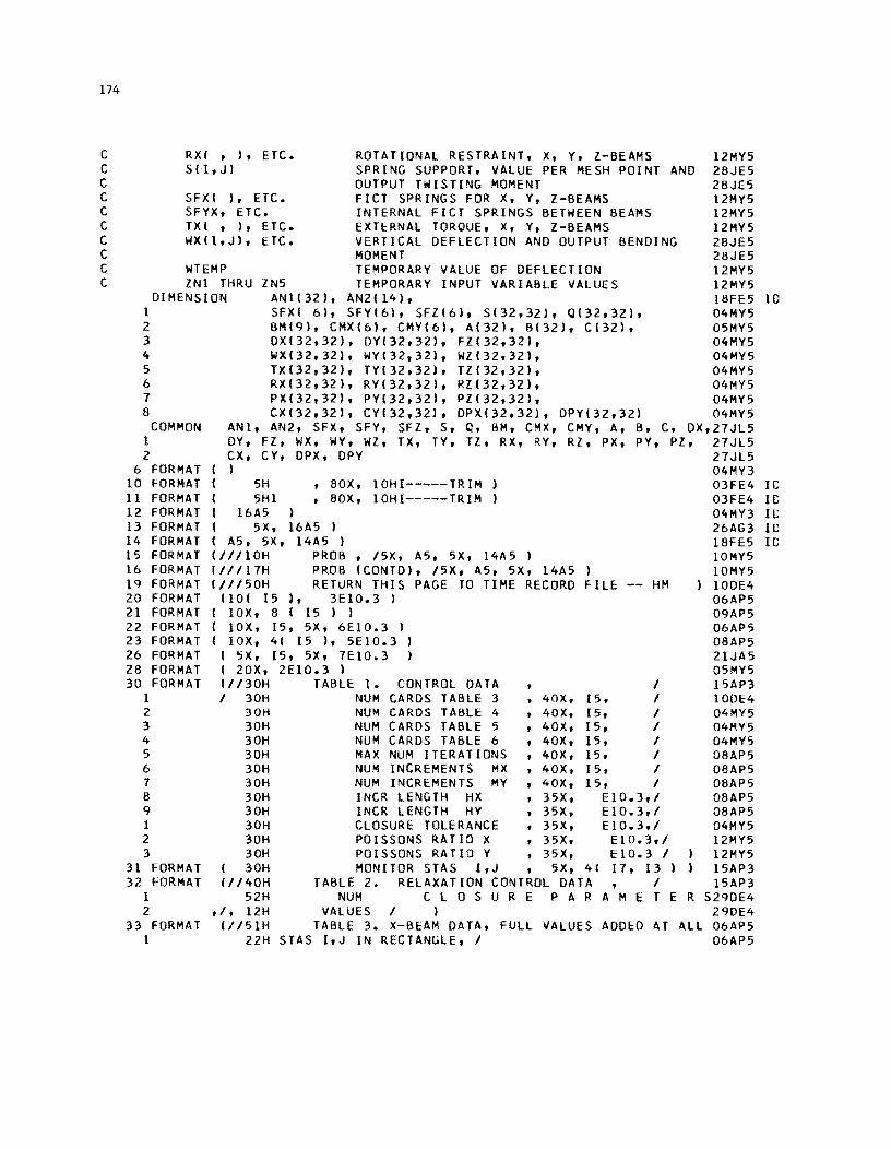
174
C RXI , ), ETC. ROTATIONAL RESTRAINT, X, y, l-BEAMS 12MY5 C SII,J) SPRING SUPPORT, VALUE PER MESH POINT AND 28JE5 C OUTPUT TWISTING MOMENT 28JE5 C SFXI ), ETC. FICT SPRINGS FOR X, Y, Z-BEAMS 12MY5 C SFYX, ETC. INTERNAL FICT SPRINGS BETWEEN BEAMS 12MY5 C TXI , ), ETC. EXTERNAL TORQUE, X, Y, Z-BEAMS 12MY5 C WXII,J), ETC. VERTICAL DEFLECTION AND OUTPUT BENDING 28JE5 C MOMENT 28JE5 C WTEMP TEMPORARY VALUE OF DEFLECTION 12MY5 C lNI THRU ZN5 TEMPORARY INPUT VARIABLE VALUES 12MY5
DIMENSION ANI(32), AN2(14), 18FE5 10 1 SFXI 6), SFY(6), SFl(6), SI32,32), 0132,32), 04MY5 2 BM(9), CMXI6', CMYI6), A(32), B(32), C(32), 05MY5 3 DXI32,32), DYI32,32), Fl(32,321, 04MY5 4 WX(32,32), WYI32,32), Wl(32,32', 04MY5 5 TX132,32), TV(32,32), Tl132,32" 04MY5 6 RX132,32', RYI32,32', Rl132,321, 04MY5 7 PX132,32), PYI32,32), Pl(32,32), 04MY5 8 CXI32,32), CYI32,32', DPX132,32), DPYI32,32) 04MY5
COMMON ANI, AN2, SFX, SFY, SFl, S, Q, BM, CMX, CMY, A, B, C, DX,27JL5 1 DY, Fl, WX, WY, Wl, TX, TY, Tl, RX, RY, Rl, PX, PY, Pl, 27JL5 2 CX, CY, DPX, DPY 27Jl5
6 FORMAT I I 04MY3 10 FORMAT I 5H , 80X, 10HI-----TRIM 03FE4 Ie 11 FORMAT I 5Hl ,80X, 10HI-----TRIM 03FE4 Ie 12 FORMA T I 16A5 , 04MY3 If': 13 FORMAT ( 5X, 16A5 I 26AG3 Ie 14 FORMAT I A5, 5X, 14A5 , 18FE5 Ie 15 FORMAT 111/lOH PROB , 15X, A5, 5X, 14A5 ) IOMY5 16 FORMAT 111117H PROB ICONTD), 15X, A5, 5X, 14A5 ) 10MY5 19 FORMAT 1II150H RETURN THIS PAGE TO TIME RECORD FilE -- HM IODE4 20 FORMAT 1101 15 I, 3EIO.3) 06AP5 21 FORMAT ( lOX, 8 I 15 ) ) 09AP5 22 FORMAT ( lOX, 15, 5X, 6EIO.3 ) 06AP5 23 FORMAT I lOX, 41 15 ), 5EIO.3 ) 08AP5 26 FORMAT I 5X, 15, 5X, 7EIO.3 ) 21JA5 28 FORMAT I 20X, 2EIO.3 ) 05MY5 30 FORMAT 1I130H TABLE I. CONTROL DATA I 15AP3
I I 30H NUM CARDS TABLE 3 ,40X, 15, I 10DE4 2 30H NUM CARDS TABLE 4 ,40X, 15, I 04MY5 3 30H NUM CARDS TABLE 5 ,40X, 15, I 04MY5 4 30H NUM CARDS TABLE 6 ,40X, 15, I 04MY5 5 30H MAX NUM ITERATIONS ,40X, 15, I 08AP5 6 30H NUM INCREMENTS MX ,40X, 15, I 08AP5 7 30H NUM INCREMENTS MY ,40X, 15, I 08AP5 8 30H INCR LENGTH HX ,35X, EIO.3,1 08AP5 9 30H INCR LENGTH HY ,35X, EIO.3,1 08AP5 1 30H CLOSURE TOLERANCE t 35X, EI0.3,1 04MY5 2 30H POISSONS RATIO X ,35X, E10.3,1 12MY5 3 30H POISSONS RATIO Y t 35X, EIO.3 I 12MY5
31 FORMAT I 30H MONITOR STAS I,J , 5X t 4( I1t 13) 15AP3 32 FORMAT fl140H TABLE 2. RELAXATION CONTROL DATA t I 15AP3
1 52H NUM C LOS U REP A RAM E T E R S29DE4 2 tit 12H VALUES I , 29DE4
33 FORMAT 11151H TABLE 3. X-BEAM DATA, FUll VALUES ADDED AT ALL 06AP5 1 22H STAS I,J IN RECTANGLE, I 06AP5
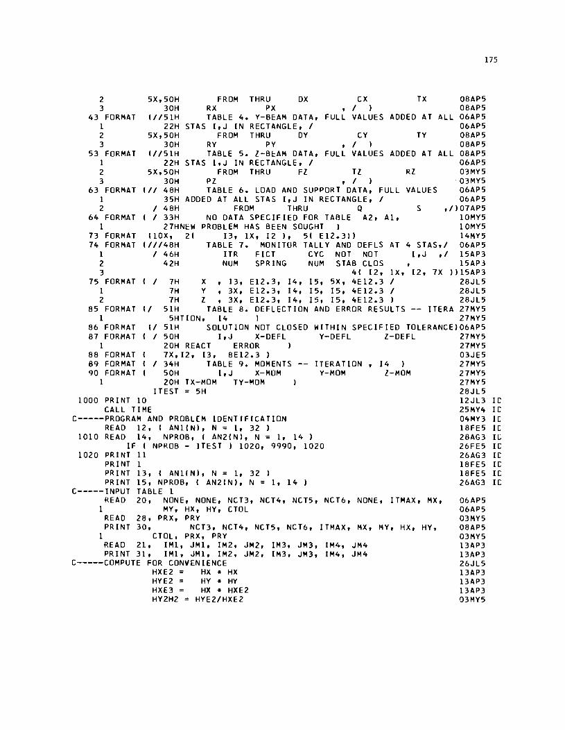
2 3
43 FORMAT 1 2 3
53 FORMAT 1 2 3
63 FORMAT 1 2
64 FORMAT 1
73 FORMAT 74 FORMAT
1 2 3
75 FORMAT 1 2
85 FORMAT 1
86 FORMAT 87 FORMAT
1 88 FORMAT B9 FORMAT 90 FORMAT
1
175
FROM THRU OX CX TX 08AP5 RX PX , I ) 08AP5 TABLE 4. Y-BEAM DATA, FULL VALUES ADDED AT ALL 06AP5
5X,50H 30H
(1/51H 22H STAS I,J IN RECTANGLE, I 06AP5
FROM THRU DY CY TY 08AP5 RY PY , I ) 08AP5 TABLE 5. l-B~AM DATA, FULL VALUES ADDED AT ALL 08AP5
5X,50H 30H
(1/51H 22H STAS I,J IN RECTANGLE, I 06AP5
5X,50H 30H
FROM THRU Fl Tl Rl 03MY5 Pl , I ) ·03MY5 TABLE 6. LOAD AND SUPPORT DATA, FULL VALUES 06AP5 (1/ 48H
35H ADDED AT ALL STAS I,J IN RECTANGLE, I 06AP5 I 48H I 33H
27HNEW (lOX, 2(
( 1/148H I 46H
42H
FROM THRU Q S ,/)07AP5 NO DATA SPECIFIED FOR TABLE A2, A1, 10MY5
PROBLEM HAS BEEN SOUGHT ) 10MY5 13, lX, 12), 5( E12.3)) 14MY5
TABLE 7. MONITOR TALLY AND oEFLS AT 4 STAS,I 06AP5 ITR FICT CYC NOT NOT I,J,I 15AP3 NUM SPRING NUM STAB CLoS, 15AP3
4( 12, lX, 12, 7X ))15AP3 (I 7H X, 13, E12.3, 14, 15, 5X, 4E12.3 I 28JL5
7H Y, 3X, E12.3, 14, 15, 15, 4E12.3 I 28JL5 7H l, 3X, E12.3, 14, 15, 15, 4E12.3 ) 28JL5
(I 51H TABLE 8. DEFLECTION AND ERROR RESULTS -- ITERA 27MY5 5HTIoN, 14 I 27MY5
(I 51H SOLUTION NOT CLOSED WITHIN SPECIFIED ToLERANCE)06AP5 ( I 50H I,J X-DEFL Y-DEFL l-DEFL 27MY5
20H REACT ERROR ) 27MY5 7X,12, 13, 8E12.3} 03JE5
I 34H TABLE 9. MOMENTS ITERATION, 14 ) 27MY5 50H I,J X-MOM V-MOM l-MoM 27MY5 20H TX-MoM TY-MoM 27MY5
!TEST = 5H 28JL5 1000 PRINT 10
CALL TIME 12Jl3 IC 25MY4 IC
C-----PRoGRAM AND PROBLEM IDENTIFICATION READ 12, I ANlIN), N = 1, 32 }
1010 READ 14, NPRoB, I AN2IN), N = 1, 14 } IF ( NPRoB - ITEST ) 1020, 9990, 1020
1020 PRINT 11 PR I NT 1 PR I NT 13, { AN 1 IN), N = 1, 32 ) PRINT 15, NPRoB, ( AN2IN), N = 1, 14 )
C-----INPUT TABLE 1 READ 20, NONE, NONE, NCT3, NCT4, NCT5, NCT6, NONE, ITMAX, MX,
1 MY, HX, HY, CToL READ 28, PRX, PRY PRINT 30, NCT3, NCT4, NCT5, NCT6, ITMAX, MX, MY, HX, HY,
1 CToL, PRX, PRY READ 21, IM1, JM1, 1M2, JM2, 1M3, JM3, IM4, JM4 PRINT 31, IM1, JM1, 1M2, JM2, 1M3, JM3, IM4, JM4
C-----CoMPUTE FOR CONVENIENCE HXE2 = HX" HX HYE2 = HY .. HY HXE3 = HX" HXE2 HY2H2 = HYE2/HXE2
04MY3 Ie 18FE5 Ie 2BAG3 II: 26FE5 Ie 26AG3 Ie 18FE5 Ie 18FE5 Ie 26AG3 Ie
06AP5 06AP5 03MY5 08AP5 03MY5 13AP3 13AP3 26JL5 13AP3 13AP3 13AP3 03MY5
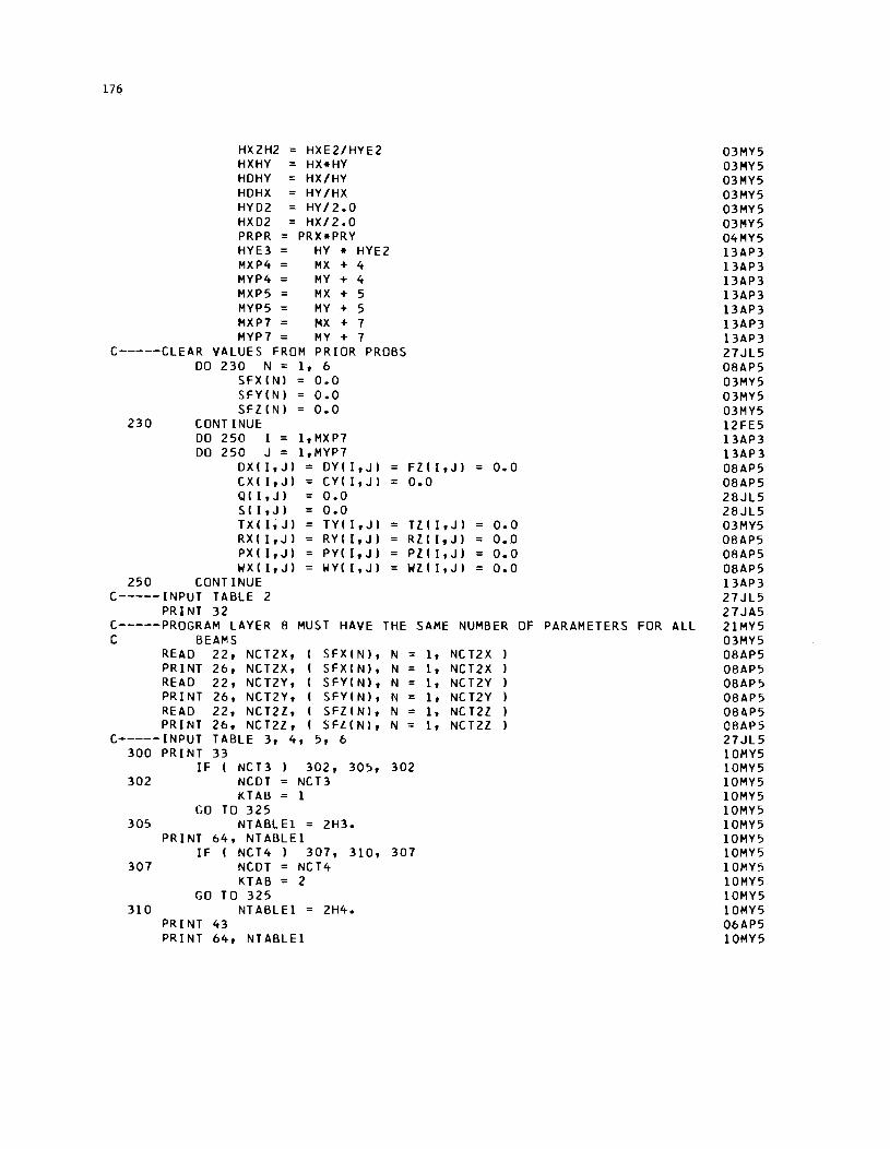
176
HX2H2 HXE2/HYE2 HXHY HX-HY HDHY HX/HY HDHX HY/HX HYD2 HY/2.0 HXD2 HX/2.0 PRPR PRX*PRY HYE3 HY * HYE2 MXP4 MX + 4 MYP4 MY + 4 MXP5 MX + 5 MYP5 MY + 5 MXP7 MX + 7 MYP7 MY + 7
C-----CLEAR VALUES FROM PRIOR PROBS
230
DO 230 N = 1, 6 SFX(N) :: 0.0 SFYtNI 0.0 SFllNI 0.0
CONTINUE: DO 250 I = I,MXP7 DO 250 J = I,MYP7
DXII,JI = DYII,JI CXII,JI = CYII,JI QII,JI 0.0 S(I,J) = 0.0 TXII,JI TYII,JI RXII,JI RYII,JI PXII,JI = PYII,JI WXII,JI WYII,JI
250 CONTINUE C-----INPUT TABLE 2
PRINT 32
= FltI,JI = 0.0 0.0
TZII,JI 0.0 RlII,JI = 0.0 PlII,JI = 0.0 WlII,JI = 0.0
C-----PROGRAM LAYER 8 MUST HAVE THE SAME NUMBER OF PARAMETERS FOR ALL C BEAMS
READ 22, NCT2X, SFXINI, N PRINT 26, NCT2X, SFXINI, N READ 22, NCT2Y, SFYIN), N PRINT 26, NCT2Y, SFYINI, N READ 22, NCT2l, SFlINI, N = PRINT 26, NCT2l, SFlINI, N =
C-----INPUT TABLE 3, 4, 5, 6 300 PRINT 33
302
305
307
310
IF I NCB NCDT KTA~
GO TO 325
302, 305, 302 NCB 1
NTABLE1 = 2H3. PRINT 64, NTABLEI
IF I NCT4) 307, 310, 307 NCDT NCT4 KTAB = 2
GO TO 325 NTABLEI = 2H4.
PRINT 43 PRINT 64, NTABLEI
1, NC T2X 1, NCT2X 1, NCT2Y 1, NC T2Y 1, NC T2l 1, NCT2l
03MY5 03MY5 03MY5 03MY5 03MY5 03MY5 04MY5 13AP3 13AP3 13AP3 13AP3 13AP3 13AP3 13AP3 27JL5 08AP5 03MY5 03MY5 03MY5 12FE5 13AP3 13AP3 08AP5 08AP5 28JL5 28JL5 03MY5 08AP5 08AP5 08AP5 13AP3 27JL5 27JA5 21MY5 03MY5 08AP5 08AP5 08AP5 08AP5 08f4P5 08AP5 27JL5 10MY5 10MY5 10MY5 10MY5 10MY5 10MY5 10MY5 10MY5 10MY5 10MY5 10MY5 10MY5 06AP5 10MY5
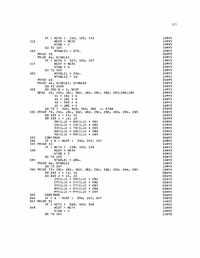
312
315
317
320
IF I NCT5 312, 315, NCDT NCT5 KTAB 3
GO TO 325 NTABLE1 = 2H5.
PRINT 53 PRINT 64, NTABLE1
IF I NCT6 ) 317, 320, NCDT NCT6 KTAB = 4
GO TO 325 NTABLEl = 2H6. NT ABLE2 = 1H
PRINT 63 PRINT 64, NTABLE1, NTABLE2
GO TO 1000
312
317
325 DO 390 N = 1, NCOT READ 23, IN1, JN1, IN2, JN2, lN1, lN2, lN3,lN4,lN5
11 IN1 + 4 J 1 IN 1 + 4 12 = IN2 + 4 J2 = JN2 + 4
GO TO I 330, 340, 350, 360 ), KTAB 330 PRINT 73, IN1, JN1, IN2, JN2, lN1, lN2, lN3, lN4, lN5
DO 335 I = 11, 12 DO 335 J = J1, J2
OX I I , J ) OX I I, J) + l N 1 CXII,J) CXII,J) + lN2 TXII,J) TXII,J) + lN3 RXII,J) RX( I,J) + lN4 PXII,J) PXII,J) + lN5
335 CONTINUE 336 IF ( N - NCOT) 390, 337, 337 337 PRINT 43
IF I NCT4) 338, 339, 338 338 NCOT = NCT4
KTAB = 2 GO TO 325
339 NTABLE1 = 2H4. PRINT 64, NTABLE1
GO TO 347 340 PRINT 73, IN1, JN1, IN2, JN2, lN1, lN2, lN3, lN4, lN5
DO 345 I = Il, 12 DO 345 J = J1, J2
DYII,J) OYII,J) + lNl CY(I,J) CYII,J) + lN2 TY( I,J) TY( I,J) + lN3 RY(I,J) = RY(I,J) + lN4 PYIltJ) PY(I,J) + lN5
345 CONTINUE 346 IF ( N - NCOT) 390, 347, 347 347 PRINT 53
IF (NCT5 348, 349, 348 348 NCOT NCT5
KTAB = 3 GO TO 325
10MY5 10MY5 10MY5 10MY5 10MY5 06AP5 10MY5 10MY5 10MY5 10MY5 10MY5 10MY5 10MY5 06AP5 10MY5 10MY5 10MY5 25MY5 16MY5 16MY5 16MY5 16MY5 07AP5 03MY5 08AP5 08AP5 03MY5 03MY5 03MY5 03MY5 03MY5 06AP5 10MY5 14MY5 14MY5 10MY5 10MY5 10MY5 10MY5 10MY5 10MY5 03MY5 08AP5 08AP5 03MY5 03MY5 03MY5 03MY5 03MY5 06AP5 10MY5 14MY5 14MY5 10MY5 10MY5 10MY5
177
178
349 NTABLE1 = 2H5.
350
355 356 357
358
359
PRINT 64, NTABLE1 GO TO 357
PRINT 73, IN1, JN1, IN2, JN2, IN1, DO 355 I = 11, 12 DO 355 J = J1, J2
FIII,JI FZII,JI TlII,JI TZII,JI RIII,JI RIII,JI PIII,JI PIII,JI
CONTINUE
+ IN1 + IN3 + IN4 + IN5
IF I N - NCDT I 390, 357, 357 PRINT 63
I F I NCT6 NCDT KTAB
358, 359, 358 NCT6 4
GO TO 325 NT ABLEl = NTABLE2 =
PRINT 64, NTABLE1, GO TO 1000
2H6. 1H NTABLE2
IN2, IN3, IN4, IN5
360 PRINT 73, IN1, JN1, IN2, JN2, IN1, lN2 DO 365 I = 11, 12
365 390
DO 365 J = J1, J2 QII,JI QII,JI + IN1 S(I,JI = SII,Jl + IN2
CONTINUE CONTINUE
CALL TIME PRINT 74, IM1, JMI, 1M2, JM2, 1M3, JM3, IM4, JM4
C-----BEGIN MAIN SOLUTION
280
500
DO 280 I = 1, MXP7 DO 280 J = 1, MYP7
DPYII,J) PRY-DYII,J) DPXII,JI = PRX*DXII,JI
CONTINUE NS = 0
DO 860 NC = 1, ITMAX NS NS + I
IF I NS - NCT2X NS 1
501, 501, 500
C C-----SOLVE
501 X-BEAMS
KSTX 0 DO 560 J 4, MYP4 DO 540 I 3,MXP5
C-----ESTABLISH ITERATION CONTROL PARAMETERS
503
505
1 2
506
IF I DXII,JI * DYII,JI I 505,503, 505 SFYX = QFY = 0.0
GO TO 507 DO 506 N = I, 3
L J + N - 2 BMIN+31 = DYII,Ll-I WYII,L-ll - 2.0*WYII,Ll + WYII,
L+ll II HYE2 + DPY(I,Ll-IWXll-1,Ll - 2.0-WXII,Ll +WXII+1,Ll I I HXE2
CONTINUE
10MY5 10MY5 10MY5 03MY5 08AP5 08AP5 08AP5 03MY5 03MY5 03MY5 06AP5 10MY5 14MY5 14MY5 10MY5 10MY5 10MY5 10MY5 10MY5 10MY5 10MY5 08AP5 08AP5 08AP5 08AP5 08AP5 06AP5 06AP5 08AP5 10MY5
31MY5 31MY5 19MY5 19MY5 03MY5 25AG4 04MY5 25AG4 08AP5 27JL5
27JL5 04DE64 01MA3 13AP3 27JL5 24FE5 08AP5 12FE5 12FE5 11 JE 5 03MY5 25MY5 03MY5 12FE 5
1 2 3 4 5 6
1 2 3 4 5 6
507 508
GO 509
1 510
1 2 3 4 5 6
QAY I BM(41 - 2.0* BMI5) + BMI61 1* HDHY + 1- 0.25 * HDHY * RYCI,J-lI * WY(I,J-21 + 0.25 *HDHY* I RYII,J-ll + RY(l,J+IJI* WYII,JI - 0.25 *HDHY* RYII,J+11 * WYII,J+21 - HX * PYII,JI * WYII,J-ll + HX * I PYII,JI + PYII,J+lI 1 * WYII,JI - HX * PYC I,J+ll * WYII,J+l) I I HXHY
OTMY I WYII-l,J-lI * CYII,JI - WYlI-l,JI * (CYII,JI +CYII,J+l) I + WY(I-l,J+lI * CYII,J+l) - WYII.J-ll * I CYII,JI + CYII+I,JI I + WYII,JI*ICYII,J) + CYII,J+ll + CYII+I,JI + CYII+l,J+llI - WYII,J+lI * ICYII,J+lI+ CYII+l,J+lI ) + WYII+l,J-ll * CYII+I,JI -WYII+l,JI * ( CYII+l,JI + CYII+I,J+ll ) + WYII+l,J+ll * CYII+l,J+l) I I HXHY
SFYX = SFYINSI QFY = SFYX * WYII,J) - QAY - QTMY
IF! FlII,JI* DXII,JI I 509, 508, 509 SFlX = OFl = 0.0
TO 516 DO 510 N = 1, 3
K 1+N-2 BMIN+61 = FlIK,JI*( WlIK-l,Jl -2.0* WlIK,Jl +
WlIK+l,J) I I HXE2 CONTINUE
QAl = I BM(7) - 2.0 *BMIS) + BM(9) II HX + 1- 0.25 * HX * RlII-l,JI * Wlll-2,J) + 0.25* HX"* I Rlll-l,JI + RlII+I,JI 1* WlII,JI - 0.25* HX * RlII+I,J) * WlII+2,JI -HXE2* PllI,JI * Wlll-l,JI +HXE2* I PlII,JI + PllI+l,JI * WlII,JI -HXE2* PlII+I,JI * WlII+I,J) I HXE3
SFlX = SFlINS) OFl = SFlX * WlII,Jl - QAl
C-----COMPUTE X-BEAM MATRIX COEFFS 516 AA HY2H2 * DXII-l,J) - RXII-l,J) * HDHX I 4.0
BB = -2.0 * HY2H2 *IDXll-l,J) + DXII,JI ) 1 I CXII,J) + CXII,J+lI ) 2 - HY * PXII,J)
CC = HY2H2 * I OX(I-l,J) + 4.0 * DXII,JI + OXII+I,J) ) 1 + ICXI I,J)+CX( I ,J+lI+CXI l+l,J)+CX( I+l,J+1I1 2 + HY * I P X I [ , J) + P X I 1+1, J I I 3 + HDHX * IRXII-l,JJ + RXII+l,JI I I 4.0 4 + HXHY * I SII,JI + SFYX + SFlX )
DD -2.0 * HY2H2 * ( DXII,J) + DXII+l,J) 1 I CXII+l,J) + CXII+l,J+ll I 2 - HY * PXII+I,JI
EE = HY2H2 * DXII+l,J) - RXII+I,J) * HDHX I 4.0 FF HXHY*I QII,J) +QFY +QFl )
1 -0.5/HX *ITZII-l,J)-TlII+I,JIl * HXHY 1 - HXD2 * I TYII,J-l) - TYII,J+l) ) 1 - HYD2*1 TXII-l,JI - TXII+I,J) ) + I-CXII,JI* 2 CWXlI-l,J-lI - WX(J,J-lI 1- CXII,J+lI*IWXlI-l,J+lI 3 -WXII,J+ll ) + CXII+l,JI*1 WXII,J-ll - WXII+I,J-1I1 4 +CXII+l,J+l)*1 WXIl,J+l)- WXII+I,J+l) ) I 5 - I DPXII-l,J) * I WYII-l,J-ll - 2.0 * WYI 1-1 ,J) 6 +WYII-l,J+lIl - 2.0*DPXII,JI*1 WYII,J-ll - 2.0*
24MY5 IlJE5 21MY5 21MY5 25MY5 25MY5 27MY5 03MY5 03MY5 03MY5 05MY5 03MY5 03MY5 03MY5 08AP5 24MY5 08AP5 04MY5 12FE5 24FE5 21JA5 08AP5 08AP5 llFE5 08AP5 IlJE5 21MY5 21MY5 25MY5 25MY5 27MY5 08AP5 OSAP5 27Jl5 06MY5 06MY5 19MY5 27MY5 06MY5 19MY5 03JE5 06MY5 10MY5 06MY5 19MY5 03JE5 06MY5 03MY5 27MY5 21MY5 21MY5 03MY5 03MY5 lOMY5 llJE5 03MY5
179
180
7 8
C-----COMPUTE
WYII,JI + WYII,J+111 + DPXII+1,J)*1 WYII+1,J-11 -2.0* WYII+1,J) + WYII+1,J+1I I )
X-BEAM CONTINUITY COEFFS
521
531 532
IF
E AA * BII-21 + BB DEN = E * Bll-11 + AA * CII-21 + CC IDENI 531, 521, 531 G 0.0
GO TO 532 G C I I I B I I I A I I I
= - 1.0 I DEN G * EE G * I E * C I 1-11 + DD G * I E * All-I. + AA * AII-2J - FF
540 CONTINUE C-----COMPUTE X-BEAM DEFLS
DO 550 L = 3,MXP5 I MX + 8 - L WTEMP = WXII,JI WXII,JI = AliI + Bill * WXII+1,JI + CIII * WXII+2,JI
C-----COUNT STAS WHERE X-BEAMS NOT STABILIZED
C
545 546 550 560
IF I DXII,JI * DYII,JI I 545, 550,545 IF I ABSF I WXII,JI - WTEMP • - CTOL I 550,550,546
KSTX = KSTX + 1 CONTINUE CONTINUE
C-----SET EXTERIOR PLATE DEFLECTIONS DO 570 I = 3, MXP5
J = 3
570 CONTINUE
WXII,JI = WYII,JI J = MYP5 WXII,JI = WYII,JI
03MY5 03MY5 27JL5 03MY5 10MY5 13AP3 08JL4 13AP3 08JL4 03MY5 03MY5 03MY5 13AP3 27JL5 13AP3 13AP3 08AP5 08AP5 27JL5 4SE64 08AP5 13AP3 13AP3 13AP3 28JL5 27JL5 12MA5 12MA5 12MY5 12MA5 12MY5 12MA5
WXI3,31 = 2.0* WX13,41 - WX(3,51 02JE5 WXIMXP5,31 = 2.0*WXIMXP5,41 - WXIMXP5,51 02JE5 WXI3,MYP51 = 2.0*WXI3,MYP41 - WXI3,MY+31 02JE5 WXIMXP5,MYP51=2.0*WXIMXP5,MYP41 - WXIMXP5,MY+31 02JE5
C-----SOLVE Y-BEAMS. 27JL5 KSTY = 0 29AP3
DO 660 I 4, MXP4 01MA3 DO 640 J 3,MYP5 l3AP3
C-----ESTABLISH ITERATION CONTROL PARAMETERS 27JL5
603
605
1 2
606
1 2 3 4 5
IFI DXII,JI * DYII,JI I 605,603,605 24FE5 SFXY = QFX = 0.0 08AP5
GO TO 607 12FE5 DO 606 N = 1, 3 1 2 F E 5
K I + N - 2 01MA3 BMINI = DXIK,JI *1 WXIK-1,JI -2.0*WXIK,JI + WXIK+1,JII03MY5
CONTINUE QAX
I HXE2 + DPXIK,JI*I WYIK,J-11 -2.0*WYIK,J' • 25MY5 WYIK,J+1111 HYE2 03MY5
IBM(1) - 2.0-BMI21 • BMI31 I * HDHX + I - 0.25*HDHX* RXll-1,JI * WXII-2,JI + 0.25*HDHX* I RXll-1,JI + RXII+1,JI I * - 0.25*HDHX* RXII+1,JI * WXII+2,JI - HY * P X I I , J I * W X I 1-1 , J I + HY * I PXII,JI + PXII+1,JI I * WXII,JI
WXII,JI
12FE5 24MY5 27JL5 27MY5 27MY5 25MY5 25MY5
6
1 2 3 4 S 6
607 608
GO 609
1 610
1 2 3 4 S 6
- HY * PXII+1,JI * WXII+1,JI 1/ HXHY QTMX = I WXII-1,J-ll* CXII,JI - WXII-1,JI*1 CXII,JI
+ CXII,J+lIl + WXII-1,J+1I * CXII,J+1I - WXII,J-1I *ICXII,JI + CXII+1,JII + WXII,JI * ICXII,JJ + CXII,J+11 + CXII+1,JI + CXII+1,J+11 I - WXII,J+11 * I C X I I , J + 11 + C X I 1+ 1 , J + 11 I + W X I I + 1 ,J-1I * CXII+1,JI - WXII+1,JI * ICXII+1,JI + CXII+1,J+1I + WXII+1,J+11 * CXII+1,J+1I 1/ HXHY
SFXY = SFXINSI QFX = SFXY * WXII,JI - QAX - QTMX
IFI Flll,JI* DYII,JI' 609,608,609 SFZY = QFZ = 0
TO 616 DO 610 N = 1, 3
K = I + N - 2 BMIN+61 FZIK,JI *1 WZIK-1,JI - 2.0* WZIK,JJ +
WlIK+1,JI / HXE2
27MYS 03MYS 04MYS 14MYS 04MYS 04MYS 04MYS 04MYS 08APS 24MYS 08APS 02JES 12FES 24FES 19JAS 08APS 08APS
CONTINUE 11FES QAZ = I BMI71 - 2.0 *BM181 + BMI91 II HX 08APS
+ I - 0.2S*HX * RZII-1,JI * WZII-2,JI 27JLS + 0.2S* HX * I RZII-1,JI + RZII+1,JI 1* WZII,JI 21MYS - 0.2S* HX * RlII+1,JI * WlII+2,JI 21MYS -HXE2* PlII.JI * WZII-1,JI 2SMYS +HXE2* I PZII,JI + PlII+1,JI * WZII.JI 2SMYS -HXE2* PlII+l,JI * WlII+1,JI / HXE3 27MYS
SFZY = SFZINSI 08APS QFZ = SFZY * Wlll,JJ - QAZ 08APS
C-----COMPUTE Y-BEAM MATRIX COEFFS 27JL5 616 AA HX2H2 * DYII,J-1) - RYII,J-11 * HDHY I 4.0 06MY5
1
1 2 3 4
1
1 1 1 2 3 4 5 6 7 8
BB = -2.0 * HX2H2 * IDYl I,J-1I + DYII,JI I 06MYS I CYII,JI + CYII+1,JI I - HX .PYII,JI 27MYS
CC HX2H2 * I DYII,J-11 + 4.0 * DYII,J) + DYII,J+11 06MYS + ICYII,JI+CYII+1,JI+CYII,J+1'+CYII+1,J+11 19MYS + HX * PYII,JI + HX *PYII,J+l) 03JES +IHDHY/4.01 * I RYII,J-1) + RYII,J+ll 06MYS + HXHY * I SII,J) + SFXY + SFlY I 06MYS
DD -2.0 * HX2H2 * I DYII,JI+DYII,J+11 I 06MYS I CYII,J+11 + CYII+1,J+1' ) -HX *PYII,J+11 03JES
EE = HX2H2 * DYII,J+11 -IHDHY I 4.01. RYII,J+11 06MYS FF = HXHY*I QII,JI + QFX + QFl I 04MY5
-O.S/HX *ITlll-1,JI-Tlll+1,JII * HXHY 27MYS - HYD2 • I TXII-1,JI - TXII+1,JI I 27JLS -HXD2*(TYII,J-1I - TYII,J+1I I 10MYS + I - CYII,J) * I WYII-1,J-1I -WYII-1,JI'-CYII+1,JI*llJES IWYII+1,J-1I - WYII+1,JI 1+ CYII,J+1I*IWYII-1,JI 10MYS - WYII-1,J+1) 1+ CYII+1,J+11*IWYII+1,JI-WYII+1,J+1110MYS II - I DPYII,J-1I*IWXII-1,J-1I-2.0*WXII,J-1I 10MYS + WXII+1,J-11 I - 2.0* DPYII,JI*( WXll-1,JI 10MYS - 2.0*WXII,JI + WXII+1,JI I + DPYII,J+11* 10MYS I WX(I-1,J+1) -2.0* WXII,J+lI +WXII+1,J+1I1 04MYS
C-----COMPUTE Y-BEAM CONTINUITY COEFFS 27JLS E = AA * BIJ-21 + BB 04MYS DEN E * BIJ-1' + AA * CIJ-21 + CC 04MYS
IF IDENI 631, 621, 631 13AP3 621 G 0.0 08JL4
GO TO 632 13AP3
181
182
631 632
G - 1.0 I DEN G * EE G * I E * CIJ-1) + DD
C I J)
BI J)
AI J) G * I c * AIJ-1) + AA * AIJ-2) - FF ) 640 CONTINUE
C-----COMPUTE Y-8EAM DEFLS DO 650 L = 3,MYP5
J = MY + 8 - L WTEMP = WY I I, J) WYII,J) = AIJ) + 81J) * WYII,J+ll
C-----COUNT STAS WHERE Y-8EAMS NOT STABILIZED
645 646 650 660
IF I DXII,J) * DYII,J) ) 645,650,645 IF I ABSF I WYII,J) - WTEMP ) - CTOL )
C-----SET
KSTY KSTY + 1 CONTINUE CONTINUE EXTERIOR PLATE DEFLECTIONS DO 670 J = 3, MYP5
I = 3 WYII,J) = WXII,J) I = MXP5 WYII,J) = WXII,J)
670 CONTINUE C C C-----SOLVE Z BEAMS
700
KS TZ = 0 IF I NCT2Z) 700, 790, 700 DO 760 J = 4, MYP4 DO 740 I = 3, MXP5
C-----ESTASLISH ITERATION CONfROL PARAMETERS
702 703
705
IF I FI14,J)) 702, 760, 702 IF I FIII,J) * DXII,J) ) 705, 703,
SFXI = QFX = 0.0 GO TO 707 DO 706 N = I, 3
K = I + N - 2
705
+ CIJ) * WYII,J+2)
650, 650, 646
08JL4 04MY5 04MY5 05MY5 13AP3 27JL5 13AP3 13AP3 08AP5 08AP5 27JL5 4SE64 08AP5 13AP3 13AP3 13AP3 12MY5 12MA5 12MA5 12MY5 12MA5 12MY5 12MA5
03MY5 20MR5 26AP5 04MY5 04MY5 27JL5 05MY5 05MY5 04MY5 04MY5 04MY5 21JA5
SMIN) = DX I K, J) * I )1 HXE2+
WXIK-1,J)-2.0* WXIK,J) + WXIK+1,J)08AP5 1 2
706 CONTINUE
1 2 3 4 5 6
1 2 3 4 5 6
OAX
OTMX
SFXI
DPXIK,J)*IWYIK,J-1)-2.0*WYIK,J) 25MY5 + WYIK,J+ll ) I HYE2 12MY5
= I SMlll -2.0 * SM(2) + SM(3) ) *HDHX + I - 0.25*HDHX* RXII-1,J) * WXII-2,J) + 0.25*HDHX* I RXII-1,J) + RXII+1,J) ) * WXII,J) - 0.25*HDHX* RXII+1,J) * WXII+2,J) - HY * PXII,J) * WXII-1,J) + HY * I P X I I, J) + P X I 1+1, J) ) * W X I I, J) - HY * PXII+1,J) * WXII+1,J) ) I HXHY
I WXII-l,J-ll* CXII,J) - WXII-1,J)*1 CXII,J) + CXII,J+ll) + WXII-1,J+ll * CXII,J+ll - WXII,J-ll *ICXIl,J) + CXII+1,J») + WXII,J) * ICXII,J) + CXII,J+ll + CXII+1,J) + CXII+l,J+ll ) - WXII,J+ll * I CXII,J+ll + CXII+1,J+1l ) + WXII+1,J-ll • CXII+l,J) - WXII+l,J) * ICXII+1,J) + CXII+1,J+1l + WXII+1,J+1l * CXII+l,J+ll ) I HXHY = SFXINS)
04MY5 12JE5 27JL5 21MY5 21MY5 25MY5 25MY5 27MY5 21MY5 21MY5 21MY5 21MY5 21MY5 21MY5 21MY5 08AP5
707 708
709
1 2
QFX = SFXZ • WXII,J) - QAX - QTMX 07JE5 IF DYII,JI • FZII,J) ) 709, 708, 709 04MY5
SFYZ = QFY = 0.0 04MY5 GO TO 716 04MY5 DO 710 N = 1, 3 04MY5
L = J + N - 2 31DE4 BM(N+3) = DYII,L).( WYII,L-ll -2.0. WYII,L) + WYII,L+1l04MY5
)/ HYE2+ DPY(I,L).(WXll-1,L)-2.0.WXII,L) 12JE5 + WXII+1,L) ) / HXE2 12MY5
710 CONTINUE 04MY5
1 2 3 4 5 6
1 2 3 4 5 6
QAY = I BM(4) - 2.0. BM(5) + BM(6) ) * HDHY 12JE5 + 1- 0.25 *HDHY. RYII,J-ll * WYII,J-2) 27JL5 + 0.25 .HDHY* I RYII,J-ll + RYII,J+ll). WYII,J) 21MY5 - 0.25 .HDHY. RY(I,J+ll • WYII,J+2) 21MY5 - HX • PY(I,J) • WYII,J-1) 25MY5 + HX • I PYII,J) + PYII,J+ll ) • WYII,J) 25MY5 - HX • PYII,J+ll • WYII,J+ll ) / HXHY 27MY5
QTMY I WYll-1,J-ll • CYII,J) - WYll-1,J) • ICY(I,J) 21MY5 +CYII,J+ll ) + WYll-1,J+ll • CYII,J+ll - WYII,J-ll 21MY5 • I CYII,J) + CYII+l,J) ) + WYII,J).ICYII,J) + 21MY5 CYII,J+ll + CYII+1,J) + CYII+l,J+ll) - WYII,J+ll. 21MY5 ICYII,J+ll+ CYII+1,J+1l ) + WYII+1,J-ll • CYII+1,J) 21MY5 -WYII+1,J) • { CYII+1,J) + CYII+1,J+1l ) + 21MY5 WYII+1,J+1l • CYII+1,J+1) ) / HXHY 21MY5
SFYZ = SFYINS) 08AP5 QFY = SFYZ • WYII,J) - QAY - QTMY 07JE5
C-----COMPUTE Z-BEAM MATRIX COEFFS 27JL5 716 AA = FZll-1,J) - 0.25. HX • RZll-1,J) 26AP5
1 2 3 4
1 2 3
C-----COMPUTE
IF 721
BB - 2.0 • { FZll-1,J) + FZII,J) ) - HXE2 • PZII,J) 08AP5 CC FZII-l,J) + 4.0 * FZ(I,JI + FZII+1,J) 20MR5
DD EE FF
+ HXE2 • I PZII,J) + 08AP5 PZII+1,J) ) + 0.25 • HX • I RZll-1,J) 06AP5
+ RZII+1,J) ) + HXE3 • SII,J) 06AP5 + HXE3 • I SFXZ + SFYZ ) 06AP5
- 2.0 • I FZII,J) + FZII+1,J) ) - HXE2 • PZII+1,JI08AP5 FZII+1,J) - 0.25. HX • RZII+1,J) 06AP5
= HXE3. I QII,J) + QFX + QFY 21MY5 -HYD2 .(TXll-1,J)-TXII+1,J)) / HXHY 27MY5 -HXD2 .(TYII,J-ll-TYII,J+ll) / HXHY 27MY5 -0.5/HX .ITZ(I-1,J)-TZII+1,J)) ) 25MY5
Z-BEAM CONTINUITY COEFFS 27JL5 E AA. BII-21 + BB 13AP3 DEN = E • BII-ll + AA • CII-2) + CC 13AP3 (DEN) 731, 721, 731 04MY5 D 0.0 04MY5
GO TO 732 04MY5 731 732
D - 1.0 / DEN 04MY5 C( I) D. EE 04MY5 B(I) = D. ( E • ClI-1) + DD 13AP3 A(I) = D. IE. AI 1-11 + AA • AII-2) - FF ) 13AP3
740 CONTINUE 04MY5 C-----COMPUTE Z-BEAM DEFLS 27JL5
DO 750 L = 3,MXP5 04MY5 I MX + 8 - L 13AP3 WTEMP = WZ(I,J) 09HR5 WZII,J) = AlI) + BII).WZ(I+1,J) + CII) • WZII+2,J) 09MR5
183
184
C-----COUNT STAS WHERE Z-BEAMS NOT STABILIZED IF I FZII,JI I 745, 750, 745
745 IF I ABSF I WZII,JI - WTEMP I - CTOl I 750, 750, 746 746 KSTZ = KSTZ + 1 750 CONTINUE 760 CONTINUE 790 CONTINUE
C-----COUNT STAS WHERE DEFlS NOT CLOSED KCTOl 0 KCTOlZ = 0
DO 850 I = 4, MXP4 DO 850 J = 4, MYP4 IF DXII,JI" DYII,JI 1810,820,810
810 IF ABSFI WXII,JI - WYII,JI 1- CTOl) 820,820,815 815 KCTOl = KCTOl + 1 820 IF I DXII,JI + DYII,JI I .. FZII,JI I 830,850,830 830 IF DXII,JI I 840,835,840 835 IF ABSFI WZII,JI - WYII,JI 1- CTOl 850,850,845 840 IF ABSFI WZII,JI - WXII,JI 1- CTOl 850,850,845 845 KCTOlZ = KCTOlZ + 1 850 CONTINUE
C-----PRINT MONITOR DATA PRINT 75, NC, SFXINSI, NS, KSTX, WXIIMl+4,JMl+41,
1 WXIIM2+4,JM2+41, WXIIM3+4,JM3+41, WXIIM4+4,JM4+41, 2 SFYINS), NS, KSTY, KCTOl, WYIIMl+4,JMl+41, 3 WYIIM2+4,JM2+41, WYIIM3+4,JM3+41, WYIIM4+4,JM4+41, 4 SFZINSI, NS, KSTZ, KCTOlZ, WZIIMl+4,JMl+41, 5 WZIIM2+4,JM2+41, WZIIM3+4,JM3+41, WZIIM4+4,JM4+41
C C-----CONTROl ITERATION PROCESS
860 IF I KCTOl + KCTOlZ I CONTINUE
NC = ITMAX C-----COMPUTE AND PRINT RESULTS
900 CONTINUE PRINT 11 PRINT 1
900, 900, 860
PRINT 13, I ANI IN), N = 1, 32 I PRINT 16, NPROB, I AN2INI, N = 1, 14 I PRINT 85, NC
IF I KCTOl + KCTOlZ I 912, 912, 911 911 PR I NT 86 912 PRINT 87
1 2
2
DO 960 J = 3,MYP5 PRINT 6
DO 950 I IS TA JSTA =
DO 940 N
3,MXP5 I - 4 J - 4 1,3
K = I BMINI
+ N - 2
BMIN+61
l
DXIK,JI .. I 1/ HXE2+ + WYIK,J+ll FZIK,JI .. I +WZIK+l,JII
J + N - 2
WXIK-l,JI-2.0"WXIK,JI + WXIK+l,JI DPXIK,JI"IWYIK,J-11-2.0"WYIK,JI I / HYE2 WZIK-l,JI - WZ(K,JI - WZIK,JI I HXE2
27Jl5 04MY5 04MY5 26AP5 04MY5 04MY5 26AP5 27Jl5 13AP3 04MY5 04MY5 04MY5 04MY5 14MY5 04MY5 04MY5 04MY5 04MY5 04MY5 04MY5 04MY5 27Jl5 06AP5 25AP3 11JE5 31DE4 llJE5 20MR5
27Jl5 26AP5 26AP5 25AG4 27Ml5 26AP5 08MY3 ID 18FE5 ID 09MR5 28AG3 ID 06AP5 26AP5 26AP5 26AP5 26AP5 24AP3 26AP5 18AP3 18AP3 26AP5 21JA5 09MR5 25MY5 12MY5 09MR5 09MR5 01MA3
1 2
940
946
1 2 3 4 5 6
1 2 3 4 5 6
1 2 3 4 S 6
1 2
1 2
1 2 3 4 S 6
1 2 3 4 5 6
948 1
1 1 2 4
8MIN+3) = DYII,L).IWYII,L-1) -2.0.WYII,L) + WYII,L+1) 1/ HYE2+ DPYII,L).IWXII-1,LI-2.0.WXII,LI + WXII+l,Ll ) / HXE2
CONTINUE QAX = I 8M11) - 8M12) - 8M(2) + 8M(3) ) • HDHX
+ I - 0.25.HDHX. RXII-l,J) • WXII-2,J) + 0.25.HDHX. 1 RXII-l,J) + RX(I+l,J) ) • WXII,J) - 0.25.HDHX. RXII+l,J) • WX(I+2,J) - HY • PXII,J) • WXII-l,J) + HY • I PXII,J) + PXII+l,J) ) • WXII,J) - HY • PXII+l,J) • WXII+l,J) ) / HXHY
QAY = I 8M(4) - 8MIS) - 8MIS) + 8M(6) ) • HDHY + I - 0.25 .HDHY. RYII,J-l) • WYII,J-2) + 0.2S .HDHY. I RYII,J-l) + RYII,J+11). WYII,J) - 0.2S .HDHY. RYII,J+l) • WYII,J+2) - HX • PYII,J) • WYII,J-l) + HX • I PYII,J) + PY(l,J+l) ) • WYII,J) - HX • PYII,J+lI • WY( I,J+1) ) / HXHY
QAZ = I 8M17) - 8M18) - 8M(8) + 8M(9) ) / HX + I -0.25. HX • RZII-l,J) • WX(I-2,J) + 0.25. HX • I RZII-l,J) + RZCI+1,J) ) • WZCI,J) - 0.25. HX • RZII+l,J) • WZII+2,J) -HXE2. PZII,J) • WZII-1,J) +HXE2. I PZII,J) + PZII+1,J) ) • WZCI,J) -HXE2. PZII+l,J) • WZII+1,J) ) / HXE3
CMX(2) =ICXII,J)+CXII,J+l'+CXII+l,J+l)+CXtI+l,J) ).0.250 • C WXCI-l,J-1) - WXII-1,J+l) - WXCI+l,J-l) + WXCI+l,J+l» / I 4.0 • HX • HY )
CMY(5) :-ICYII,J)+CYII,J+1)+CYII+1,J+1)+CY(I+1,J».0.2S0 • I WYII-l,J-l) - WYII-1,J+1) - WYII+1,J-l) + WYII+l,J+l» / C 4.0 • HY • HX )
QTMX = I WXII-l,J-l). CXII,J) - WXII-l,J).C CX(I,J) + CXII,J+l}) + WXCI-l,J+l) • CXII,J+l) - WXII,J-l) .ICXII,J) + CXII+l,J» + WXII,JI • (CXII,J) + CXII,J+l) + CXCI+l,J) + CXII+1,J+ll ) - WXII,J+l) • C CXCI,J+l) + CXCI+l,J+l) ) + WXII+1,J-l) • CXII+l,J) - WXII+l,J) • (CXCI+l,J) + CXCI+l,J+l) ) + WXII+l,J+l) • CXII+l,J+l) ) / HXHY
QTMY = I WYII-l,J-l) • CYII,J) - WYCI-l,J) • ICYII,J) +CYII,J+l) ) + WYII-l,J+l) • CYCI,J+l) - WYCI,J-l) • C CYII,J) + CYII+l,J) ) + WYCI,J).CCYCI,J) + CYII,J+l) + CY(I+l,JI + CYCI+l,J+l}) - WYCI,J+l) • (CYII,J+l)+ CYII+l,J+l) ) + WYII+l,J-l) • CYII+l,J) -WYtI+l.J) • t CYII+1.J) + CVII+1,J+1) ) + WYII+l,J+l) • CYII+l.J+l) ) / HXHY
REACT = QAX + QAY + QAZ + QTMX + QTMY IF I DXII,J) • DYII,J') 948. 946, 948
ERROR 0.0 GO TO 949
DENO
ERROR =
WXII,J) / WXII,J) + WYCI.J) / WYII.J) + WZII,J) / WZCI,J) Q(I,J' - REACT - SII,J) • ( WXII,J) +
WZ I It J' + WY ( I, J, ) / DENO - HYD2 • I TX!I-l,J' - TXII+l,J) ) / HXHY - HXD2 • I TYII.J-l) - TYC I,J+l) ) / HXHY -0.5/HX. ITZ(I-l,J) - TZCI+l,J)'
09MR5 12JE5 12MY5 26AP5 10JE5 27JL5 10JE5 10JE5 25MY5 25MY5 27MY5 10JE5 27JL5 10JES 10JES 2SMY5 27JLS 27MY5 OSMY5 27JL5 21MY5 21MY5 25MYS 25MY5 27MY5 12MY5 09MR5 09MR5 12MY5 09MRS 09MRS 03MYS 04MY5 04MYS 04MYS 04MYS 04MYS 04MYS 03MYS 03MYS 03MYS 05MYS 03MYS 03MV5 03MY5 24MY5 04MYS 06MY5 04MY5 21MV5 21MY5 07AP5 21MY5 llJE5 llJE5 21MY5
185
186
949 PRINT 88, ISTA, JSTA, WXII,JI, WYII,JI, WIII,JI, REACT, ERROR 27MY5 WXII-2,J-21= BMI21 27MY5 WYII-2,J-21= BHI51 27MY5 W I I 1-2, J- 2 I = BMI81 27MY5 Q I 1-2, J-2 ) = CMXI21 27MY5 SII-2,J-2) CMYI51 27MY5
950 CONTINUE 04MY5 960 CONTINUE 04MY5
PRINT 89, NC 27MY5 PRINT 90 27MY5
DO 980 J = 3, MYP5 27MY5 PRINT 6 27MY5
DO 970 I 3, MXP5 27MY5 ISTA = I - 4 27MY5 JSTA = J - 4 27MY5
PRINT 88, ISTA, JSTA, WXII-2,J-21, WYII-2,J-21, Wlll-2,J-21, 27MY5 1 QII-2,J-21, SII-2,J-21 27MY5
970 CONTINUE 27MY5 980 CONTINUE 27MY5
CAll TIME 25MY4 10 GO TO 1010 26AG3 10
9990 CONTINUE 12MR5 10 9999 CONTINUE 04MY3 10
PRINT 11 08MY3 10 PRINT 1 18FE5 10 PRINT 13, I ANlIN), N = 1, 32 ) 18FE5 10 PRINT 19 26AG3 10 END 04MY3 10 END

APPENDIX 11
PROGRAM LAYER 8 AND GUIDE FOR DATA INPUT

!!!!!!!!!!!!!!!!!!!"#$%!&'()!*)&+',)%!'-!$-.)-.$/-'++0!1+'-2!&'()!$-!.#)!/*$($-'+3!
44!5"6!7$1*'*0!8$($.$9'.$/-!")':!
APPENDIX 11. PROGRAM IAYER 8
Program LAYER 8 is a FORTRAN 63 language computer program written to
solve the equations presented in Chapter 7 for a plate-over-beam system. The
program requires a large capacity digital computer such as the CDC 1604. The
program requires approximately 26,000 words of core memory and compiles in
approximately 2 minutes. A brief explanation of several items pertinent to
the use of this program follows. An input form to aid in coding problems for
this program is included in this Appendix.
Input Parameters
Data is input to this program by two methods. These two methods have
been detailed in Appendix 5 for program IAYER 7. Data input is arranged in
tables. Table 1 contains constants and control data. Of interest are the two
Poisson constants. Poisson's ratio "x" pertains to a stress application in
the x-direction and is defined by Eq A7.2. Poisson's ratio "y" is defined in
a similar manner by Eq A7.4. The monitor data allow four intersections of the
system to be observed for convergence and closure rate. The monitor stations
are designated by the x-y layer coordinates but output includes deflections
for all layers existing at the specified station.
Table 2 includes closure parameter data. The same number of values are
used on all layers. Tables 3, 4, and 5 pertain to the x, y, and z-beams of
the layered system. Table 6 is for all load and support data. A blank card
is required as the last card of any data run to stop the program.
Program Resul ts
The results from the program are also arranged in Tables. Tables 1, 2,
3, 4, 5, and 6 are reflections of the input data. Table 7 includes the
189

190
monitor data output. Table 8 includes the deflections at each station of each
of the beams along with a reaction and an error term. The error term is the
unbalance of load equilibrium at the intersection and is computed only from
statics. Table 9 gives the plate and beam moments as well as the torsional
moments in the plate.

GUIDE FOR DATA INPUT FOR LAYER 8
with Supplementary Notes
extract from
A FINITE-ELEMENT METHOD FOR BENDING ANALYSIS OF LAYERED STRUCTURAL SYSTEMS
by
Wayne B. Ingram and Hudson Matlock
August 1965

This page replaces an intentionally blank page in the original --- CTR Library Digitization Team
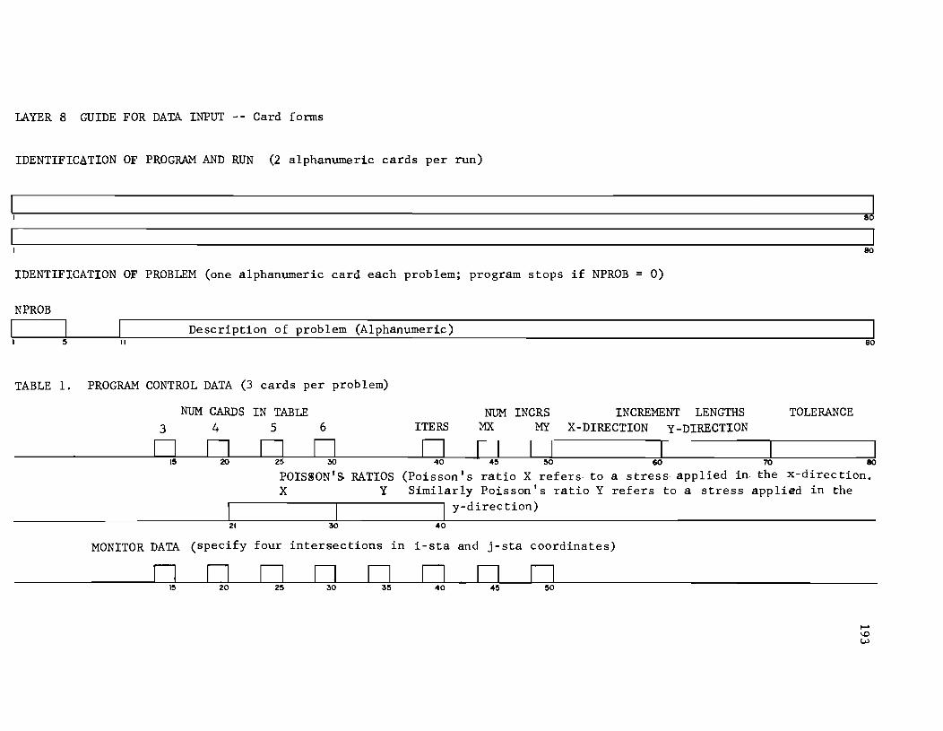
LAYER 8 GUIDE FOR DATA INPUT - - Card fonns
IDENTIFICaTION OF PROGRAM AND RUN (2 alphanumeric cards per run)
I J 1 8
80
IDENTIFICATION OF PROBLEM (one alphanumeric card each problem; program stops if NPROB 0)
NPROB
Description of problem (Alphanumeric) II
TABLE 1. PROGRAM CONTROL DATA (3 cards per problem)
NUM CARDS 3 4
o 0
21 30 40
INCRS MY
INCREMENT LENGTHS X-DIRECTION Y-DlRECTION
TOLERANCE
80
I I I 60 70 80
a stress applied in. the x-direction. refers to a stress applied in the
MONITOR DATA (specify four intersections in i-sta and j-sta coordinates)
o o o o o D o o 20 30 40

This page replaces an intentionally blank page in the original --- CTR Library Digitization Team
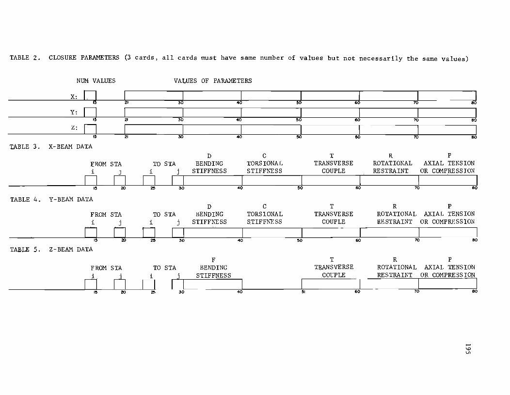
TABLE 2. CLOSURE PARAMETERS (3 cards, all cards must have same number of values but not necessarily the same values)
NUM VALUES VALUES OF PARAMETERS
X: q I I I I I I I 21 30 40 50 60 70 80
Y: 0 I I I I I I I 15 21 30 40 50 60 70 80
Z: n I I I I I I I 15 21 30 40 50 60 70 80
TABLE 3. X-BEAM DATA D C T R P
EROM STA TO STA BENDING TORSIONAL TRANSVERSE ROTATIONAL AXIAL TENSION i J i j STIFFNESS STIFFNESS COUPLE RESTRAINT OR COMPRESSION
n n n I I I I I I I 15 20 25 30 40 50 60 70 80
TABLE 4. Y-BEAM DATA D C T R P
FROM STA TO STA BENDING TORSIONAL TRANSVERSE ROTATIONAL AXIAL TENS ION i j i j STIFFNESS S.TIFFNESS COUPLE RESTRAINT OR COMPRE SS ION
n n n 15 20 25 30 40 50 60 70 80
TABLE 5. Z-BEAM DATA
F T R P FROM STA TO STA BENDING TRANSVERSE ROTATIONAL AXIAL TENSION i n i j STIFFNESS COUPLE RESTRAINT OR COMPRESSION
n n I I I I I I 15 20 2!1 30 40 51 60 10 80

This page replaces an intentionally blank page in the original --- CTR Library Digitization Team
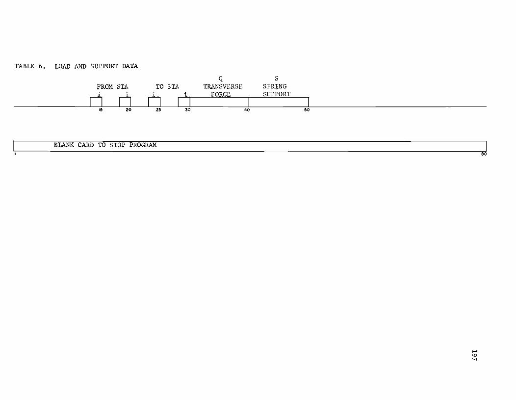
TABLE 6. LOAD AND SUPPORT DATA
FROM STA TO STA
cJ 0 o Iii I~ 20 2~ 30
BLANK CARD TO STOP PROGRAM
Q TRANSVERSE
FORCE
40
S SPRING SUPPORT
~o
80

This page replaces an intentionally blank page in the original --- CTR Library Digitization Team
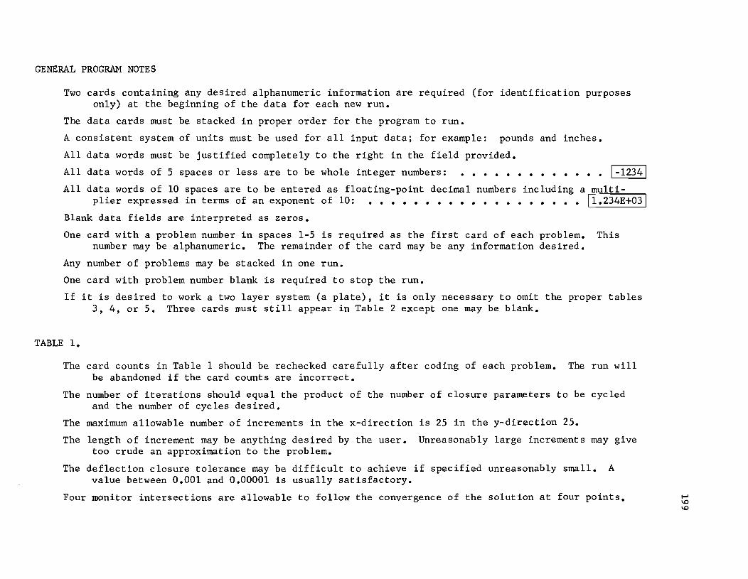
GENERAL PROGRAM NOTES
Two cards containing any desired alphanumeric information are required (for identification purposes only) at the beginning of the data for each new run.
The data cards must be stacked in proper order for the program to run.
A consistent system of units must be used for all input data; for example: pounds and inches.
All data words must be justified completely to the right in the field provided.
All data words of 5 spaces or less are to be whole integer numbers: . . . . . . . . . . . . . 1-12341
All data words of 10 spaces are to be entered as floating-point decimal numbers including a multiplier expressed in terms of an exponent of 10: ••••••••••••••••••• 11.234E+031
Blank data fields are interpreted as zeros.
One card with a problem number in spaces 1-5 is required as the first card of each problem. This number may be alphanumeric. The remainder of the card may be any information desired.
Any number of problems may be stacked in one run.
One card with problem number blank is required to stop the run.
If it is desired to work a two layer system (a plate), it is only necessary to omit the proper tables 3, 4, or 5. Three cards must still appear in Table 2 except one may be blank.
TABLE 1.
The card counts in Table 1 should be rechecked carefully after coding of each problem. The run will be abandoned if the card counts are incorrect.
The number of iterations should equal the product of the number of closure parameters to be cycled and the number of cycles desired.
The maximum allowable number of increments in the x-direction is 25 in the y-direction 25.
The length of increment may be anything desired by the user. Unreasonably large increments may give too crude an approximation to the problem.
The deflection closure tolerance may be difficult to achieve if specified unreasonably small. A value between 0.001 and 0.00001 is usually satisfactory.
Four monitor intersections are allowable to follow the convergence of the solution at four points.

This page replaces an intentionally blank page in the original --- CTR Library Digitization Team
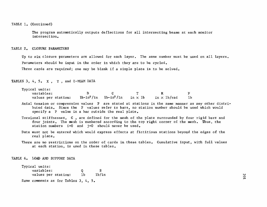
TABLE 1. (Continued)
The program automatically outputs deflections for all intersecting beams at each monitor intersection.
TABLE 2. CLOSURE PARAMETERS
Up to six closure parameters are allowed for each layer. The same number must be used on all layers.
Parameters should be input in the order in which they are to be cycled.
Three cards are required; one may be blank if a simple plate is to be solved.
TABLES 3, 4, 5. X, Y, and Z-BEAM DATA
Typical units: variables: values per station:
D 1b-in2 /in
C 1b-in2 /in
T R in X 1b in X 1b/rad
P 1b
Axial tension or compression values P are stated at stations in the same manner as any other distributed data. Since the P values refer to bars, no station number should be used which would specify a P value in a bar outside the real plate.
Torsional stiffnesses, C, are defined for the mesh of the plate surrounded by four rigid bars and four joints. The mesh is numbered according to the top right corner of the mesh. Thus, the station numbers i=O and j=O should never be used.
Data must not be entered which would express effects at fictitious stations beyond the edges of the real plate.
There are no restrictions on the order of cards in these tables. Cumulative input, with full values at each station, is used in these tables.
TABLE 6. LOAD AND SUPPORT DATA
Typical units: variables: Q values per station: 1b
Same comments as for Tables 3, 4, 5.
S 1b/in N
o ~

This page replaces an intentionally blank page in the original --- CTR Library Digitization Team
APPENDIX 12
SAMPLE INPUT AND OUTPUT FOR PROGRAM LAYER 7

!!!!!!!!!!!!!!!!!!!"#$%!&'()!*)&+',)%!'-!$-.)-.$/-'++0!1+'-2!&'()!$-!.#)!/*$($-'+3!
44!5"6!7$1*'*0!8$($.$9'.$/-!")':!
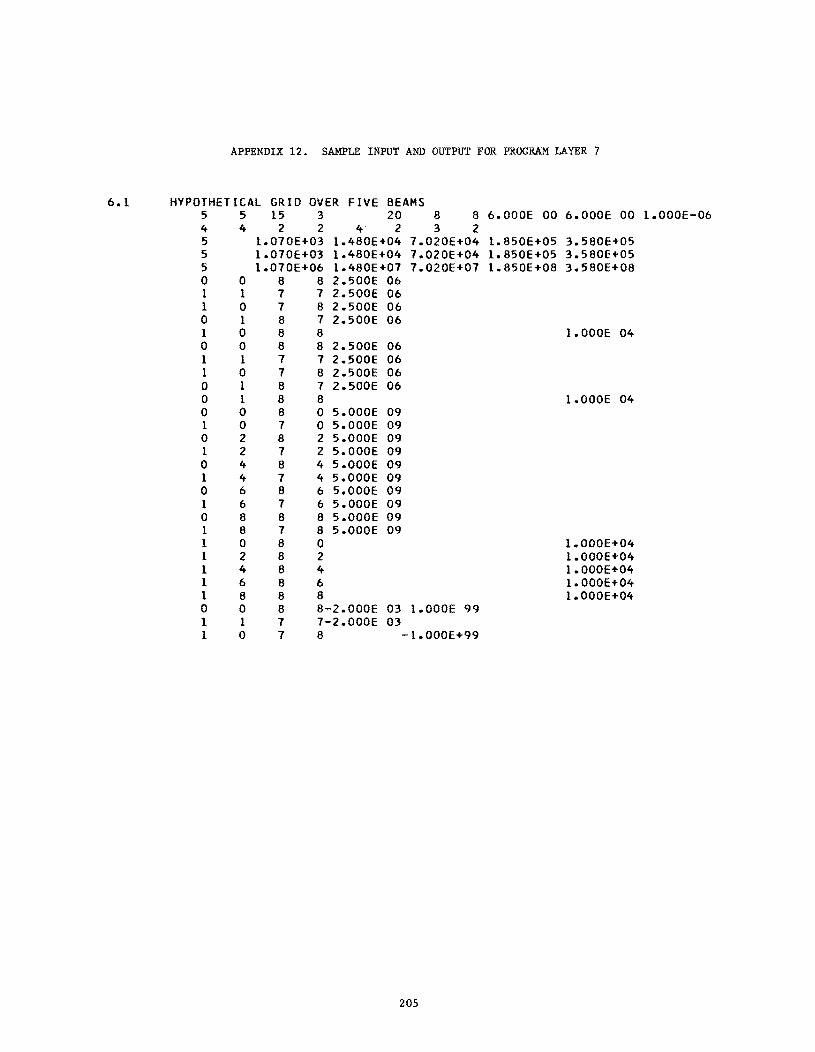
APPENDIX 12. SAMPLE INPUT AND OUTPUT FOR PROGRAM LAYER 7
6.1 HYPOTHETICAL GRID OVER FIVE BEAMS 5 5 15 3 20 8 8 6.000E 00 6.000E 00 1.000E-06 4 4 2 2 4 2 3 2 5 1.070E+03 1.480E+04 7.020E+04 1.850E+05 3.580E+05 5 I.070E+03 1.480E+04 7.020E+04 I.850E+05 3.580E+05 5 I.070E+06 1.480E+07 7.020E+07 I.850E+08 3.580E+08 0 0 8 8 2.500E 06 1 I 7 7 2.500E 06 I 0 7 8 2.500E 06 0 I 8 7 2.500E 06 1 0 8 8 I.OOOE 04 0 0 8 8 2.500E 06 I I 7 7 2.500E 06 I 0 7 8 2.500E 06 0 I 8 7 2.500E 06 0 I 8 8 I.OOOE 04 0 0 8 0 5.000E 09 I 0 7 0 5.000E 09 0 2 8 2 5.000E 09 I 2 7 2 5.000E 09 0 4 8 4 5.000E 09 I 4 7 4 5.000E 09 0 6 8 6 5.000E 09 1 6 7 6 5.000E 09 0 8 8 8 5.000E 09 I 8 7 8 5.000E 09 1 0 8 0 I.OOOE+04 I 2 8 2 1.OOOE+04 I 4 8 4 I.OOOE+04 I 6 8 6 I.OOOE+04 I 8 8 8 I.OOOE+04 0 0 8 8-2.000E 03 I.OOOE 99 1 I 7 7-2.000E 03 1 0 7 8 -I.OOOE+99
205
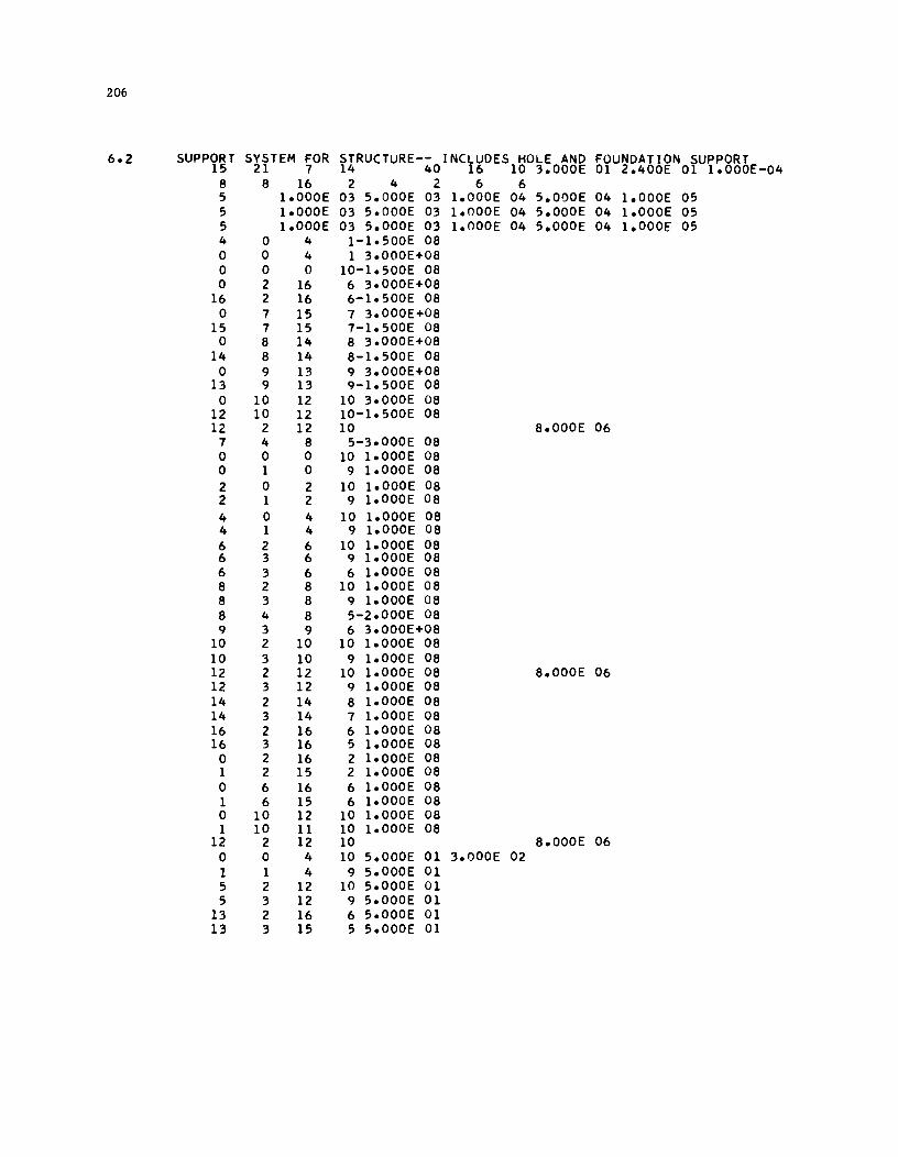
206
6.2 SUPPORT SYSTEM FOR STRUCTURE-- INCLUDES HOLE AND FOUNDATION SUPPORT 15 21 7 14 40 16 10 3.000E 01 2.400E 01 1.000E-04
8 8 16 2 4 2 6 6 5 1.000E 03 5.COOE 03 I.COOE 04 5.000E 04 1.000E 05 5 1.000E 03 5.COOE 03 1.000E 04 5.000E 04 1.000E 05 5 1.000E 03 5.000E 03 1.000E 04 5.000E 04 1.000E 05 4 0 4 1-1.500E 08 0 0 4 1 3.000E+08 0 0 0 10-1.500E 08 0 2 16 6 3.000E+08
16 2 16 6-1.500E 08 0 7 15 7 3.000E+08
15 1 15 1-1.500E 08 0 8 14 8 3.000E+08
14 8 14 8-1.500E 08 0 9 13 9 3.000E+08
13 9 13 9-1.500E 08 0 10 12 10 3.000E 08
12 10 12 10-1.500E 08 12 2 12 10 8.000E 06
1 4 8 5-3.000E 08 0 0 0 10 1.000E 08 0 1 0 9 1.000E 08 2 0 2 10 1.000E 08 2 1 2 9 1.000E 08 4 0 4 10 1.000E 08 4 1 4 9 1.000E 08 6 2 6 10 1.000E 08 6 3 6 9 1.000E 08 6 3 6 6 1.000E 08 8 2 8 10 1.000E 08 8 3 8 9 1.000E 08 8 4 8 5-2.000E 08 9 3 9 6 3.000E+08
10 2 10 10 1.000E 08 10 3 10 9 1.000E 08 12 2 12 10 1.000E 08 8.000E 06 12 3 12 9 1.000E 08 14 2 14 8 1.000E 08 14 3 14 7 1.000E 08 16 2 16 6 1.000E 08 16 3 16 5 1.000E 08
0 2 16 2 1.000E 08 1 2 15 2 1.000E 08 0 6 16 6 1.000E 08 1 6 15 6 1.000E 08 0 10 12 10 1.000E 08 1 10 11 10 1.000E 08
12 2 12 10 8.000E 06 0 0 4 10 5.000E 01 3.000E 02 1 1 4 9 5.000E 01 5 2 12 10 5.000E 01 5 3 12 9 5.000E 01
13 2 16 6 5.000E 01 13 3 15 5 5.000E 01
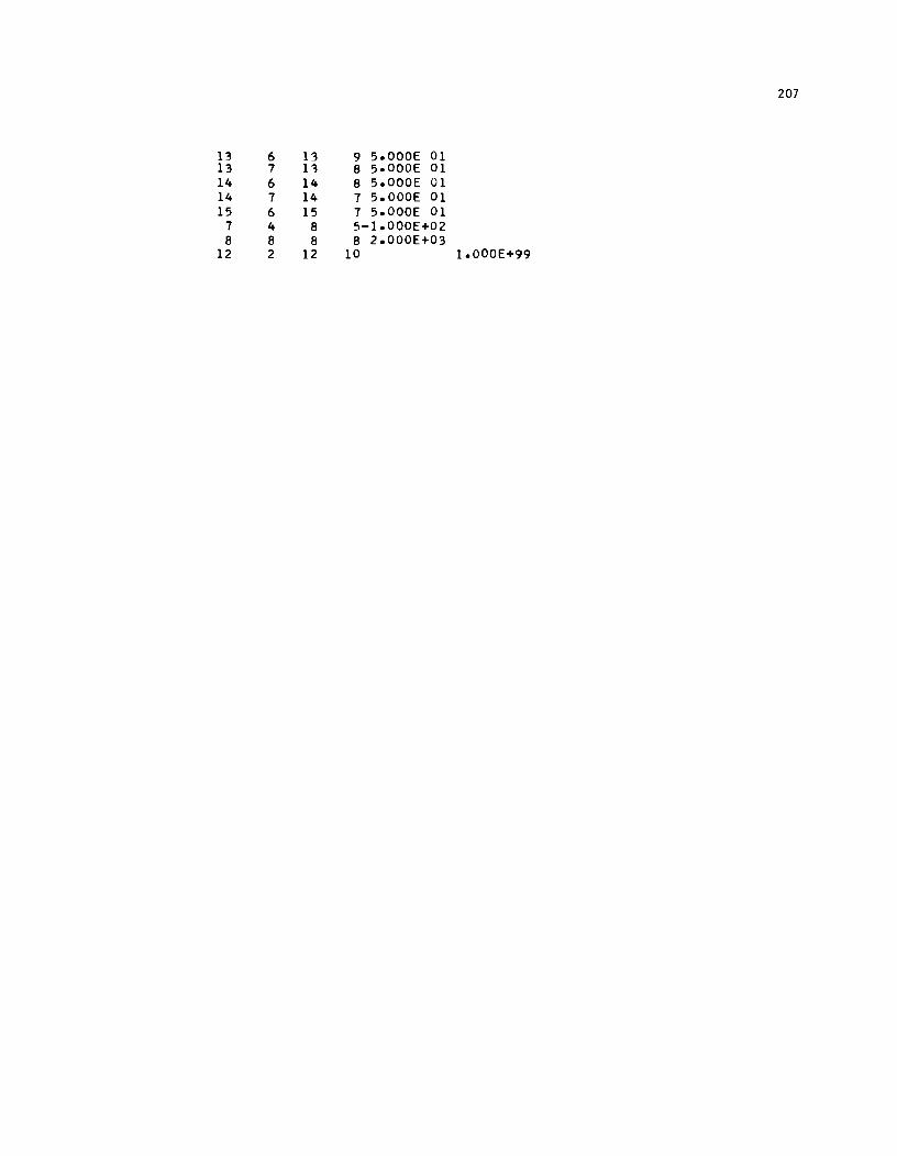
207
13 6 13 9 5.000E 01 13 7 13 8 5.000E 01 14 6 14 8 5.000E 01 14 7 14 7 5.000E 01 15 6 15 7 5.000E 01
7 4 8 5-1.000E+02 8 8 8 8 2.000E+03
12 2 12 10 1.000E+99
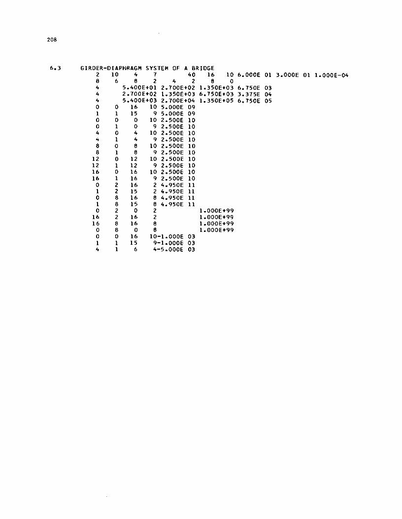
208
6.3 GIRDER-DIAPHRAGM SYSTEM OF A BRIDGE 2 10 .4 7 40 16 10 6.000E 01 3.000E 01 1.000E-04 8 6 8 2 4 2 8 0 4 5.400E+01 2.700E+02 1.350E+03 6.750E 03 4 2.700E+02 1.350E+03 6.750E+03 3.375E 04 4 5.400E+03 2.700E+04 1.350E+05 6.750E 05 0 0 16 10 5.000E 09 1 1 15 9 5.000E 09 0 0 0 10 2.500E 10 0 1 0 9 2.500E 10 4 0 4 10 2.500E 10 4 1 4 9 2.500E 10 8 0 8 10 2.500E 10 8 1 8 9 2.500E 10
12 0 12 10 2.500E 10 12 1 12 9 2.500E 10 16 0 16 10 2.500E 10 16 1 16 9 2.500E 10
0 2 16 2 4.950E 11 1 2 15 2 4.950E 11 0 8 16 8 4.950E 11 1 8 15 8 4.950E 11 0 2 0 2 1.000E+99
16 2 16 2 1.000E+99 16 8 16 8 1.000E+99
0 8 0 8 1.000E+99 0 0 16 10-1.000E 03 1 1 15 9-1.000E 03 4 1 6 4-5.000E 03
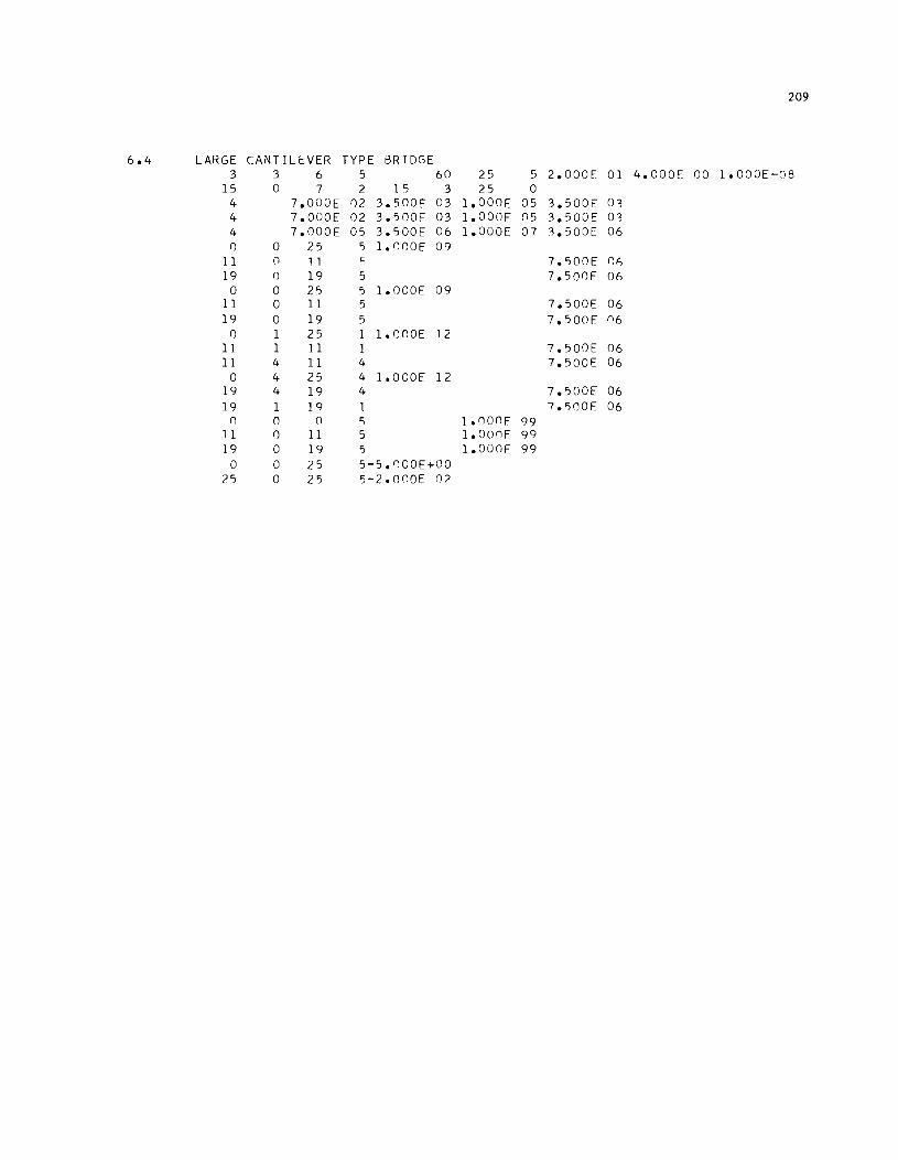
209
6.4 LARGE CANTILEVER TYPE BRIDGE 3 3 6 5 60 25 5 2.000E 01 4.000E 00 1.000E-OB
15 0 7 2 1 I) 3 25 0 4 7.000E 02 3.500E 03 1.000F 05 3.500E 0, 4 7.000E 02 3.500E 03 1.000F 05 3.500E 0, 4 7.000E 05 3.I)00E 06 1.000E 07 3.500E 06 0 0 25 I) 1.000E 09
11 0 1 1 0; 7.I)00E (1)
19 0 19 5 7.500E 06 0 0 25 5 1.000E 09
11 0 11 5 7.500E 06 19 0 19 5 7.500E fl6
0 1 25 1 1.nOOE 12 11 1 11 1 7.500E 06 11 4 11 4 7.500E 06
0 4 25 4 1.000E 12 19 4 19 4 7.500E 06 19 1 19 1 7.I)00E 06
0 0 0 0; 1.000F 99 11 0 11 5 1.00flE 99 19 0 19 5 1.000E 99
0 0 25 5-5.flOOE+OO 25 0 25 5-2.000E 07
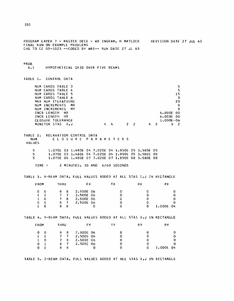
210
PROGRAM LAYER 7 - MASTER DECK - WB INGRAM. H MATLOCK FINAL RUN ON EXAMPLE PROBLEMS
REVISION DATE 27 JUL 65
CHG TO CE 05-1023 --CODED BY WBI-- RUN DATE 27 JL 65
PROB 6.1 HYPOTHETICAL GRID OVER FIVE BEAMS
TABLE 1. CONTROL DATA
NUM CARDS TABLE 3 5 NUM CARDS TABLE 4 5 NUM CARDS TAt3LE 5 15 NUM CARD5 TABLE 6 3 MAX NUM ITERATIONS 20 NUM INCREMENTS MX 8 NUM INCREMENTS MY 8 INCR LENGTH HX 6.000E 00 INCR LENGTH HY 6.000E 00 CLOSURE TOLERANCE 1.000E-06 MUN I TOR S TAS I • J 4 4 2 2 4 2 3 2
TABLE 2. RELAXATION CONTROL DATA NUM C LOS U R E PAR A M E T E R S
VALUES
5 1.0JOE 03 1.480E 04 7.020E 04 1.8S0E 05 3.580E 05 5 1. 070E 03 1.480E 04 7.020E 04 1.8S0E 05 3.580E OS 5 1.070E 06 1.480E 07 7.020E 07 1.850E 08 3.580E 08
TIME 2 MINUTES. 30 AND 6/60 SECONDS
TABLE 3. X-BlAM DATA. FULL VALUES ADDED AT ALL STAS I,J IN RECTANGLE
F-ROM THRU FX TX RX PX
0 0 8 8 2.S00E 06 0 0 0 1 1 7 7 2.S00E 06 0 0 0 1 G 7 8 2.500E 06 0 0 0 0 1 8 7 2.500E 06 0 0 0 1 0 8 8 0 0 0 1.000E 04
TABLE 4. Y-BEAM DATA, FULL VALUES ADDED AT ALL STAS I.J IN RECTANGLE
FROM THRU FY TY RY PY
0 0 8 8 2.500E 06 0 0 0 1 1 7 7 2.500E 06 0 0 0 1 0 7 8 2.500E 06 0 0 0 0 1 8 7 2.S00E 06 0 0 0 0 1 8 8 0 0 0 1.0001:: 04
TABLE 5. Z-BEAM DATA, FULL VALUES ADDED AT ALL STAS I.J IN RECTANGLE
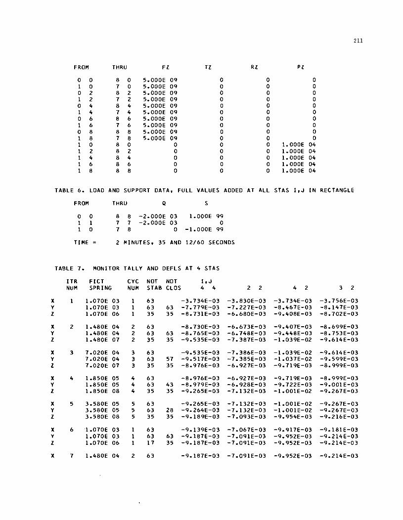
211
FROM THRU Fl T! RI PI
0 0 8 0 5.000E 09 0 0 0 1 0 7 0 5.000E 09 0 0 0 0 2 8 2 5.000E 09 0 0 0 1 2 7 2 5.000E 09 0 0 0 0 4 8 4 5.000E 09 0 0 0 1 4 7 4 5.000E 09 0 0 0 0 6 8 6 5.000E 09 0 0 0 1 6 7 6 5.000E 09 0 0 0 0 8 8 8 5.000E 09 0 0 0 1 8 7 8 5.000E 09 0 0 0 1 0 8 0 0 0 0 1.000E 04 1 2 8 2 0 0 0 1.000E 04 1 4 8 4 0 0 0 1.000E 04 1 6 8 6 0 0 0 1.000E 04 1 8 8 8 0 0 0 1.000E 04
TABLE 6. LOAD AND SUPPORT DATA, FULL VALUES ADDED AT ALL STAS I, J IN RECTANGLE
FROM THRU Q S
0 0 8 8 -2.000E 03 1.000E 99 1 1 7 7 -2.000E 03 0 1 0 7 8 0 -1.000E 99
TIME = 2 MINUTES, 35 AND 12/60 SECONDS
TABLE 7. MONITOR TALLY AND DEFLS AT 4 STAS
ITR FICT CYC NOT NOT I, J NUM SPRING NUM STAB CLOS 4 4 2 2 4 2 3 2
X 1 1.070E 03 1 63 -3.734E-03 -3.830E-03 -3.734E-03 -3.756E-03 Y 1.070E 03 1 63 63 -7.779E-03 -7.227E-03 -8.467E-03 -8.147E-03 Z 1.070E 06 1 35 35 -8.731E-03 -6.680E-03 -9.408E-03 -8.702E-03
X 2 1.480E 04 2 63 -8.730E-03 -6.673E-03 -9.407E-03 -8.699E-03 Y 1.480E 04 2 63 63 -8.765E-03 -6.748E-03 -9.448E-03 -8.753E-03 Z 1.480E 07 2 35 35 -9.535E-03 -7.387E-03 -1.039E-02 -9.614E-03
X 3 7.020E 04 3 63 -9.535E-03 -7.386E-03 -1.039E-02 -9.614E-03 Y 7.020E 04 3 63 57 -9.517E-03 -7.385E-03 -1.037E-02 -9.599E-03 Z 7.020E 07 3 35 35 -8.976E-03 -6.927E-03 -9.719E-03 -8.999E-03
X 4 1.850E 05 4 63 -8.976E-03 -6.927E-03 -9.719E-03 -8.999E-03 Y 1.850E 05 4 63 43 -8.979E-03 -6.928E-03 -9.722E-03 -9.00lE-03 Z 1.850E 08 4 35 35 -9.265E-03 -7.132E-03 -1.001E-02 -9.267E-03
X 5 3.580E 05 5 63 -9.265E-03 -7.132E-03 -1.001E-02 -9.267E-03 Y 3.580E 05 5 63 28 -9.264E-03 -7.132E-03 -1.001E-02 -9.267E-03 Z 3.580E 08 5 35 35 -9.189E-03 -7.093E-03 -9.954E-03 -9.216E-03
X 6 1.070E 03 1 63 -9.139E-03 -7.067E-03 -9.917E-03 -9.18lE-03 Y 1.070E 03 1 63 63 -9.187E-03 -7.091E-03 -9.952E-03 -9.214E-03 Z 1.070E 06 1 17 35 -9.187E-03 -7.091E-03 -9.952E-03 -9.214E-03
X 7 1.480E 04 2 63 -9.187E-03 -7.091E-03 -9.952E-03 -9.214E-03
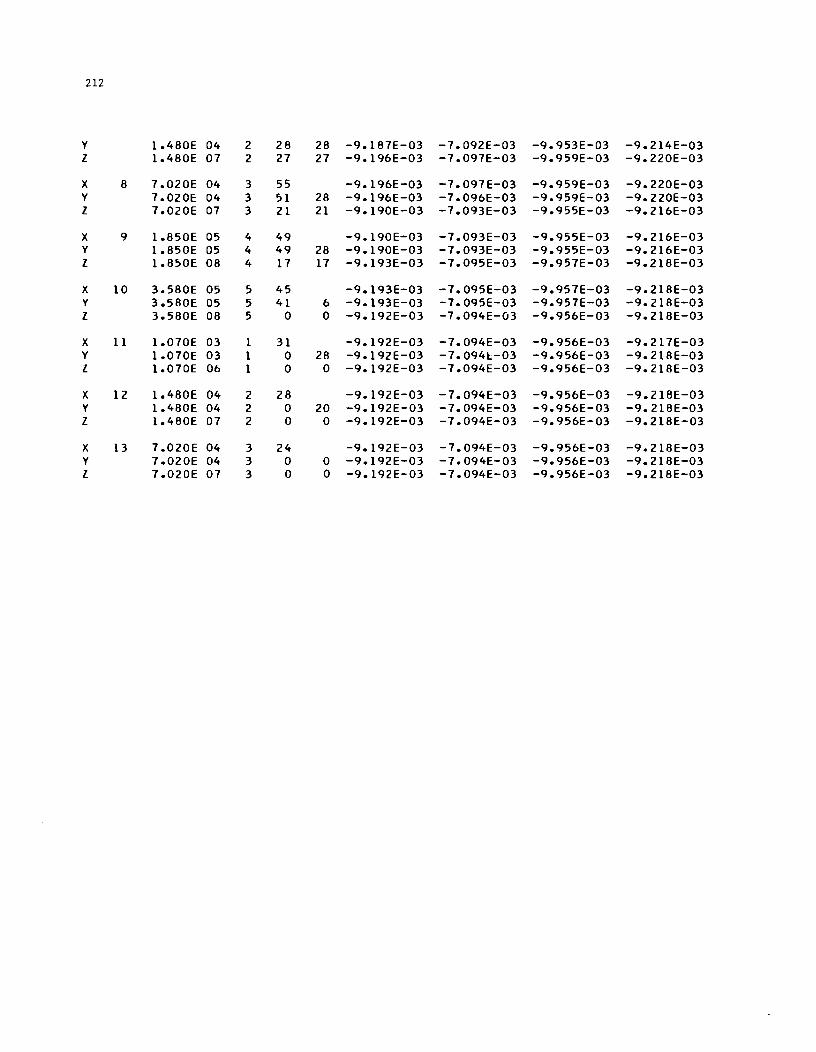
212
y 1.480E 04 2 28 28 -9.187E-03 -7.092E-03 -9.953E-03 -9.214E-03 Z 1.480E 07 2 27 27 -9.196E-03 -7.097E-03 -9.959E-03 -9.220E-03
X 8 7.020E 04 3 55 -9.196E-03 -7.097E-03 -9.959E-03 -9.220E-03 Y 7.020E 04 3 51 28 -9.196E-03 -7.096E-03 -9.959E-03 -9.220E-03 Z 7.020E 07 3 21 21 -9.190E-03 -7.093E-03 -9.955E-03 -9.216E-03
X 9 1.850E 05 4 49 -9.190E-03 -7.093E-03 -9.955E-03 -9.216E-03 Y 1.850E 05 4 49 28 -9.190E-03 -7.093E-03 -9.955E-03 -9 •. 216E-03 Z 1.850E 08 4 17 17 -9.193E-03 -7.095E-03 -9.957E-03 -9.218E-03
X 10 3.580E 05 5 45 -9.193E-03 -7.095E-03 -9.957E-03 -9.218E-03 Y 3.580E 05 5 41 6 -9.193E-03 -7.095E-03 -9.957E-03 -9.218E-03 Z 3.580E 08 5 0 0 -9.192E-03 -7.094E-03 -9.956E-03 -9.218E-03
X 11 1.070E 03 1 31 -9.192E-03 -7.094E-03 -9.956E-03 -9.217E-03 Y 1.070E 03 1 0 28 -9.192E-03 -7.094[-03 -9.956E-03 -9.218E-03 Z 1.070E 06 1 0 0 -9.192E-03 -7.094E-03 -9.956E-03 -9.218E-03
X 12 1.480E 04 2 28 -9.192E-03 -7.094E-03 -9.956E-03 -9.218E-03 Y 1.480E 04 2 0 20 -9.192E-03 -7.094E-03 -9.956E-03 -9.218E-03 Z 1.480E 07 2 0 0 -9.192E-03 -7.094E-03 -9.956E-03 -9.218E-03
X 13 7.020E 04 3 24 -9.192E-03 -7.094E-03 -9.956E-03 -9.218E-03 Y 7.020E 04 3 0 0 -9.192E-03 -7.094E-03 -9.956E-03 -9.218E-03 Z 7.020E 07 3 0 0 -9. 192E-03 -7.094E-03 -9.956E-03 -9.218E-03
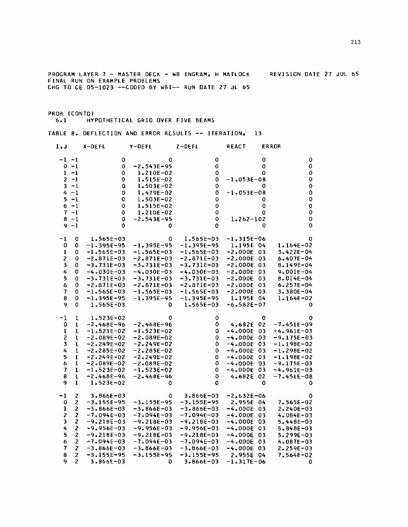
PROGRAM LAYER 1 - MASTER DECK - WB INGRAM, H MATLOCK FINAL RUN ON EXAMPLE PROBLEMS CHG TO CE 05-1023 --CODED BY WBI-- RUN DATE 21 JL 65
PROB (CONTD) 6.1 HYPOTHETICAL GRID OVER FIVE BEAMS
TABLE B. DEFLECTION AND ERROR RESULTS ITERATION,
213
REVISION DATE 21 JUL 65
13
I,J X-DEFL Y-DEFL l-DEFL REACT ERROR
-1 -1 0 0 0 0 0 0 -1 0 -2.543E-95 0 0 0 1 -1 0 1.210E-02 0 0 0 2 -1 0 1.515E-02 0 -1.053E-OB 0 3 -1 0 1.503E-02 0 0 0 4 -1 0 1.419E-02 0 -1.053E-OB 0 5 -1 0 1.503E-02 0 0 0 6 -1 0 1.515E-02 0 0 0 1 -1 0 1.210E-02 0 0 0 B -1 0 -2.543E-95 0 1.262-102 0 9 -1 0 0 0 0 0
-1 0 1.565E-03 0 1.565E-03 -1.315E-06 0 0 0 -1.395E-95 -1.395E-95 -1.395E-95 1.195E 04 1.164E-02 1 0 -1.565E-03 -1.565E-03 -1.565E-03 -2.000E 03 3.422E-04 2 0 -2.B7lE-03 -2.B7lE-03 -2. B7lE-03 -2.000E 03 6.401E-04 3 0 -3.131E-03 -3.131E-03 -3.13lE-03 -2.000E 03 B.149E-04 4 0 -4.030E-03 -4.030E-03 -4.030E-03 -2.000E 03 9.001E-04 5 0 -3.131E-03 -3.131E-03 -3.131E-03 -2.000E 03 B.014E-04 6 0 -2.B7lE-03 -2.BllE-03 -2.B7lE-03 -2.000E 03 6.251E-04 1 0 -1.565E-03 -1.565E-03 -1.565E-03 -2.000E 03 3.3BOE-04 B 0 -1.395E-95 -1.395E-95 -1.395E-95 1.195E 04 1.164E-02 9 0 1.565E-03 0 1.565E-03 -6.5B2E-01 0
-1 1 1.523E-02 0 0 0 0 0 1 -2.46BE-96 -2.46BE-96 0 4.6B2E 02 -1.451E-09 1 1 -1.523E-02 -1.523E-02 0 -4.000E 03 -4.961E-03 2 1 -2.0B9E-02 -2.0B9E-02 0 -4.000E 03 -9.115E-03 3 1 -2.249E-02 -2.249E-02 0 -4.000E 03 -1.19BE-02 4 1 -2.2B5E-02 -2.2B5E-02 0 -4.000E 03 -1.29BE-02 5 1 -2.249E-02 -2.249E-02 0 -4.000E 03 -l.l9BE-02 6 1 -2.0B9E-02 -2.0B9E-02 0 -4.000E 03 -9.115E-03 1 1 -1.523E-02 -1.523E-02 0 -4.000E 03 -4.961E-03 B 1 -2.46BE-96 -2.46BE-96 0 4.6B2E 02 -1.45lE-OB 9 1 1.523E-02 0 0 0 0
-1 2 3.B66E-03 0 3.B66E-03 -2.632E-06 0 0 2 -3.155E-95 -3.155E-95 -3.155E-95 2.955E 04 1.565E-02 1 2 -3.B66E-03 -3.B66E-03 -3.B66E-03 -4.000E 03 2.240E-03 2 2 -1.094E-03 -1.094E-03 -1.094E-03 -4.000E 03 4.0B4E-03 3 2 -9.21BE-03 -9.21BE-03 -9.21BE-03 -4.000E 03 5.44BE-03 4 2 -9.956E-03 -9.956E-03 -9.956E-03 -4.000E 03 5.B4BE-03 5 2 -9.21BE-03 -9.21BE-03 -9.21BE-03 -4.000E 03 5.299E-03 6 2 -1.094E-03 -1.094E-03 -1.094E-03 -4.000E 03 4.0B1E-03 1 2 -3.B66E-03 -3.B66E-03 -3.B66E-03 -4.000E 03 2.259E-03 8 2 -3.155E-95 -3.155E-95 -3.155E-95 2.955E 04 1.564E-02 9 2 3.866E:-03 0 3.866E:-03 -1.311E-06 0
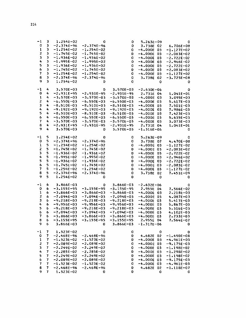
214
-1 3 1.254E-02 0 0 5.263E-09 0 0 3 -2.374E-96 -2.374E-96 0 3.738E 02 6.706E-08 1 3 -1.254E-02 -1.254E-02 0 -4.000E 03 -1.127E-02 2 3 -1.745E-02 -1.745E-02 0 -4.000E 03 -2.083E-02 3 3 -1.936E-02 -1.936E-02 0 -4.000E 03 -2.722E-:02 4 3 -1.995E-02 -1.995E-02 0 -4.000E 03 -2.946E-02 5 3 -1.936E-02 -1.936E-02 0 -4.000E 03 -2.722E-02 6 3 -1.745E-02 -1.745E-02 0 -4.000E 03 -2.083E-02 7 3 -1.254E-02 -1.254E-02 0 -4.000E 03 -1.127E-02 8 3 -2.374E-96 -2.374E-96 0 3.738E 02 -3.725E-08 9 3 1.254E-02 0 0 0 0
-1 4 3.570E-03 0 3.570E-03 -2.630E-06 0 0 4 -2.931E-95 -2.931E-95 -2.931E-95 2.731E 04 1.041E-Ol 1 4 -3.570E-03 -3.570E-03 -3.570E-03 -4.000E 03 3.095E-03 2 4 -6.550E-03 -6.550E-03 -6.550E-03 -4.000E 03 5.617E-03 3 4 -8.510E-03 -8.510E-03 -8.510E-03 -4.000E 03 7.501E-03 4 4 -9.192E-03 -9.192E-03 -9.192E-03 -4.000E 03 7.986E-03 5 4 -8.510E-03 -8.510E-03 -8.510E-03 -4.000E 03 7.423E-03 6 4 -6.550E-03 -6.550E-03 -6.550E-03 -4.000E 03 5.635E-03 7 4 -3.570E-03 -3.570E-03 -3.570E-03 -4.000E 03 3.073E-03 8 4 -2.931E-95 -2.931E-95 -2.931E-95 2.73IE 04 1.041E-Ol 9 4 3.570E-03 0 3.570E-03 -1.316E-06 0
-1 5 1.254E-02 0 0 5.263E-09 0 0 5 -2.374E-96 -2.374E-96 0 3.738E 02 4.470E-08 1 5 -1.254E-02 -1.254E-02 0 -4.000E 03 -1.127E-02 2 5 -1.745E-02 -1.745E-02 0 -4.000E 03 -2.083E-02 3 5 -1.936E-02 -1.936E-02 0 -4.000E 03 -2.722E-02 4 5 -1.9-95E-02 -1.995E-02 0 -4.000E 03 -2.946E-02 5 5 -1.936E-02 -1.936E-02 0 -4.000E 03 -2.722E-02 6 5 -1.745E-02 -1.745E-02 0 -4.000E 03 -2.083E-02 7 5 -1.254E-02 -1.254E-02 0 -4.000E 03 -1.127E-02 8 5 -2.374E-96 -2.374E-96 0 3.738E 02 7.451E-09 9 5 1.254E-02 0 0 0 0
-1 6 3.866E-03 0 3.866E-03 -2.632E-06 0 0 6 -3.155E-95 -3.155E-95 -3.155E-95 2.955E 04 7.566E-02 1 6 -3.866E-03 -3.866E-03 -3.866E-03 -4.000E 03 2.218E-03 2 6 -7.094E-03 -7.094E-03 -7.094E-03 -4.000E 03 4.087E-03 3 6 -9.218E-03 -9.218E-03 -9.218E-03 -4.000E 03 5.417E-03 4 6 -9.956E-03 -9.956E-03 -9.956E-03 -4.000E 03 5.867E-03 5 6 -9.218E-03 -9.218E-03 -9.218E-03 -4.000E 03 5.316E-03 6 6 -7.094E-03 -7.094E-03 -7.094E-03 -4.000E 03 4.102E-03 7 6 -3.866E-03 -3.866E-03 -3.866E-03 -4.000E 03 2.233E-03 8 6 -3.155E-95 -3.155E-95 -3.155E-95 2.955E 04 7.564E-02 9 6 3.866E-03 0 3.866E-03 -1.317E-06 0
-1 7 1.523E-02 0 0 0 0 0 7 -2.468E-96 -2.468E-96 0 4.682E 02 -1.490E-08 1 7 -1.523E-02 -1.523E-02 0 -4.000E 03 -4.96lE-03 2 7 -2.089E-02 -2.089E-02 0 -4.000E 03 -9.175E-03 3 7 -2.249E-02 -2.249E-02 0 -4.000E 03 -1.198E-02 4 7 -2.285E-02 -2.285E-02 0 -4.000E 03 -1.298E-02 5 7 -2.249E-02 -2.249E-02 0 -4.000E 03 -1.198E-02 6 7 -2.089E-02 -2.089E-02 0 -4.000E 03 -9.175E-03 7 7 -1.523E-02 -1.523E-02 0 -4.000E 03 -4.96IE-03 8 7 -2.468E-96 -2.468E-96 0 4.682E 02 -1.118E-07 9 7 1.523E-02 0 0 0 0
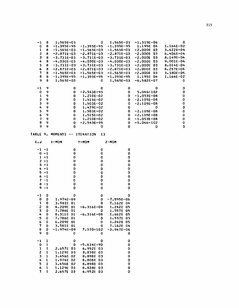
215
-1 8 1.565E-03 0 1.565E-03 -1.315E-06 0 0 8 -1.395E-95 -1.395E-95 -1.395E-95 1.195E 04 1.164E-02 1 8 -1.565E-03 -1.565E-03 -1.565E-03 -2.000E 03 3.422E-04 2 8 -2.871E-03 -2.871E-03 -2.871E-03 -2.000E 03 6.406E-04 3 8 -3.731E-03 -3.731E-03 -3.731E-03 -2.000E 03 8. 149E-04 4 8 -4.030E-03 -4.030E-03 -4.030E-03 -2.000E 03 9.001E-04 5 8 -3.731E-03 -3.731E-03 -3.731E-03 -2.000E 03 8.014E-04 6 8 -2.871E-03 -2.871E-03 -2.871E-03 -2.000E 03 6.257E-04 7 8 -1.565E-03 -1.565E-03 -1.565E-03 -2.000E 03 3.380E-04 8 8 -1.395E-95 -1.395E-95 -1.395E-95 1.195E 04 1.164E-02 9 8 1.565E-03 0 1~565E-03 -6.582E-07 0
-1 9 0 0 0 0 0 0 9 0 -2.543E-95 0 5.046-102 0 1 9 0 1.210E-02 0 -1.053E-08 0 2 9 0 1.515E-02 0 -2.105E-08 0 3 9 0 1.503E-02 0 -2.105E-08 0 4 9 0 1.479E-02 0 0 0 5 9 0 1.503E-02 0 -2.105E-08 0 6 9 0 1.515E:-02 0 -2.105E-08 0 7 9 0 1.210E-02 0 -1.053E-08 0 8 9 0 -2.543E-95 0 -5.046-102 0 9 9 0 0 0 0 0
TABLE 9. MOMENTS I TERAT ION 13
I, J X-MOM V-MOM Z-MOM
-1 -1 0 0 0 0 -1 0 0 0 1 -1 0 0 0 2 -1 0 0 0 3 -1 0 0 0 4 -1 0 0 0 5 -1 0 0 0 6 -1 0 0 0 7 -1 0 0 0 8 -1 0 0 0 9 -1 0 0 0
-1 0 0 0 0 0 0 1.974E-09 0 -7.895E-06 1 0 3.581E 01 0 7.162E 04 2 0 6.209E 01 -6.316E-08 1.242E 05 3 0 7.786E 01 0 1.557E 05 4 0 8.311E 01 -6.316E-08 1.662E 05 5 0 7.786E 01 0 1.557E 05 6 0 6.209E 01 0 1.242E 05 7 0 3.58lE 01 0 7.162E 04 8 0 -1.974E-09 7.570-102 -3.947E-06 9 0 0 0 0
-1 1 0 0 0 0 1 0 -5.634E-90 0 1 1 2.657E 03 6.952E 03 0 2 1 1.129E 03 8.838E 03 0 3 1 3.456E 02 8.898E 03 0 4 1 1.974E 02 8.808E 03 0 5 1 3.456E 02 8.898E 03 0 6 1 1.129E 03 8.838E 03 0 7 1 2.657E 03 6.952E 03 0
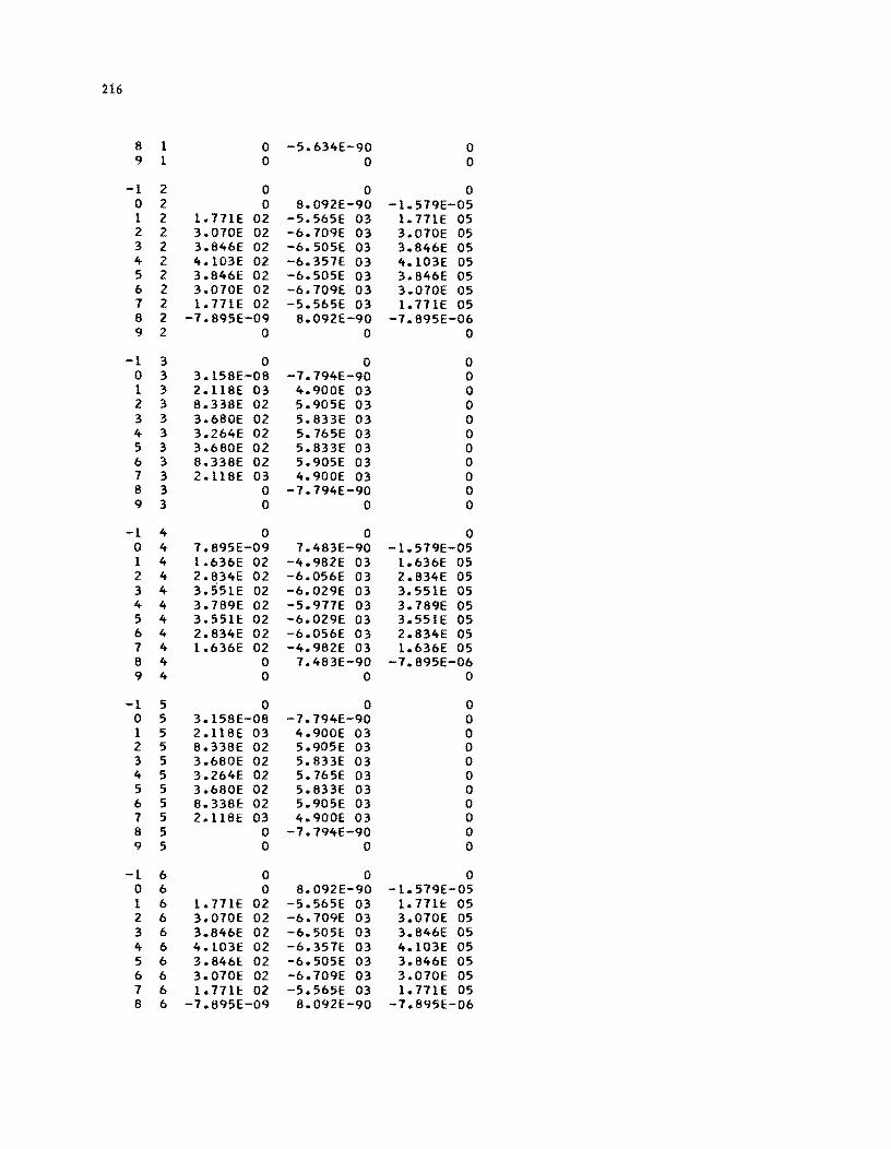
H6
8 1 0 -5.634E-90 0 9 1 0 0 0
-1 2 0 0 0 0 2 0 8.092E-90 -1.579E-05 1 2 1.771E 02 -5.565E 03 1.771E 05 2 2 3.070E 02 -6.709E 03 3.070E 05 3 2 3.846E 02 -6.505E 03 3.846E 05 4 2 4.103E 02 -6.357E 03 4.103E 05 5 2 3.846E 02 -6.505E 03 3.846E 05 6 2 3.070E 02 -6.709E 03 3.070E 05 7 2 1.771E 02 -5.565E 03 1.771E 05 8 2 -7.895E-09 8.092E-90 -7.895E-06 9 2 0 0 0
-1 3 0 0 0 0 3 3.158E-08 -7.794E-90 0 1 3 2.ll8E 03 4.900E 03 0 2 3 8.338E 02 5.905E 03 0 3 3 3.680E 02 5.833E 03 0 4 3 3.264E 02 5.765E 03 0 5 3 3.680E 02 5.833E 03 0 6 3 8.338E 02 5.905E 03 0 7 3 2.ll8E 03 4.900E 03 0 8 3 0 -7.794E-90 0 9 3 0 0 0
-1 4 0 0 0 0 4 7.895E-09 7.483E-90 -1.579E-05 1 4 I.636E 02 -4.982E 03 1.636E 05 2 4 2.834E 02 -6.056E 03 2.834E 05 3 4 3.S51E 02 -6.029E 03 3.55IE 05 4 4 3.789E 02 -5.977E 03 3.789E 05 5 4 3.551E 02 -6.029E 03 3.55IE 05 6 4 2.834E 02 -6.056E 03 2.834E 05 7 4 I.636E 02 -4.982E 03 1.636E 05 8 4 0 7.483E-90 -7.895E-06 9 4 0 0 0
-1 5 0 0 0 0 5 3.158E-08 -7.794E-90 0 1 5 2.U8E 03 4.900E 03 0 2 5 8.338E 02 5.905E 03 0 3 5 3.680E 02 5.833E 03 0 4 5 3.264E 02 5.765E 03 0 5 5 3.680E 02 5.833E 03 0 6 5 8.338E 02 5.905E 03 0 7 5 2.ll8E 03 4.900E 03 0 8 5 0 -7.794E-90 0 9 5 0 0 0
-1 6 0 0 0 0 6 0 8.092E-90 -1.579E-05 1 6 1.771E 02 -5.565E 03 1.771E 05 2 6 3.070E 02 -6.709E 03 3.070E 05 3 6 3.846E 02 -6.505£ 03 3.846E 05 4 6 4.103E 02 -6.357E 03 4.I03E 05 5 6 3.8461:: 02 -6.505E 03 3.846E 05 6 6 3.070E 02 -6.709E 03 3.070E 05 7 6 1.77IE 02 -5.565E 03 1.77IE 05 8 6 -7.895E-09 8.092E-90 -7.895E-06
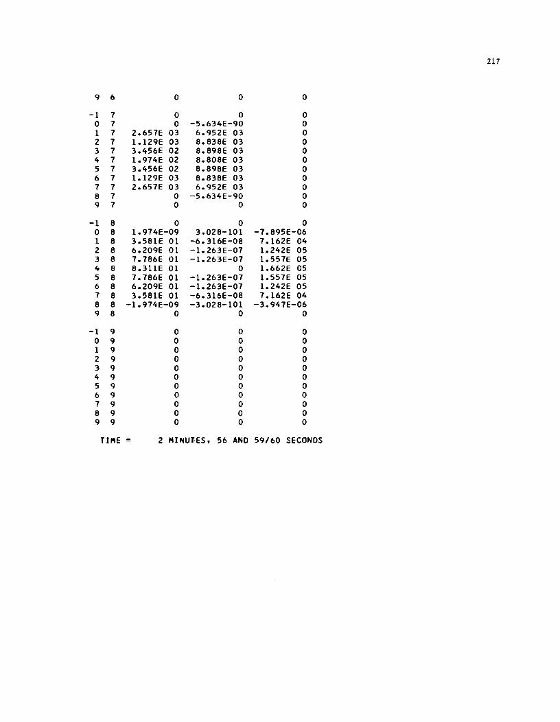
211
9 6 0 0 0
-1 7 0 0 0 0 7 0 -5.634E-90 0 1 7 2.657E 03 6.952E 03 0 2 7 1.129E 03 8.838E 03 0 3 7 3.456E 02 8.898E 03 0 4 7 1.974E 02 8.808E 03 0 5 7 3.456E 02 8.898E 03 0 6 7 1.129E 03 8.838E 03 0 7 7 2.657E 03 6.952E 03 0 8 7 0 -5.634E-90 0 9 7 0 0 0
-1 8 0 0 0 0 8 1.974E-09 3.028-101 -7.895E-06 1 8 3.581E 01 -6.316E-08 7.162E 04 2 8 6.209E 01 -1.263E-07 1.242E 05 3 8 7.786E 01 -1.263E-07 1.557E 05 4 8 8.311E 01 0 1.662E 05 5 8 7.786E 01 -1.263E-07 1.557E 05 6 8 6.209E 01 -1.263E-07 1.242E 05 7 8 3.581E 01 -6.316E-08 7.162E 04 8 8 -1.974E-09 -3.028-101 -3.947E-06 9 8 0 0 0
-1 9 0 0 0 0 9 0 0 0 1 9 0 0 0 2 9 0 0 0 3 9 0 0 0 4 9 0 0 0 5 9 0 0 0 6 9 0 0 0 7 9 0 0 0 8 9 0 0 0 9 9 0 0 0
TIME = 2 MINUTES, 56 AND 59/60 SECONDS
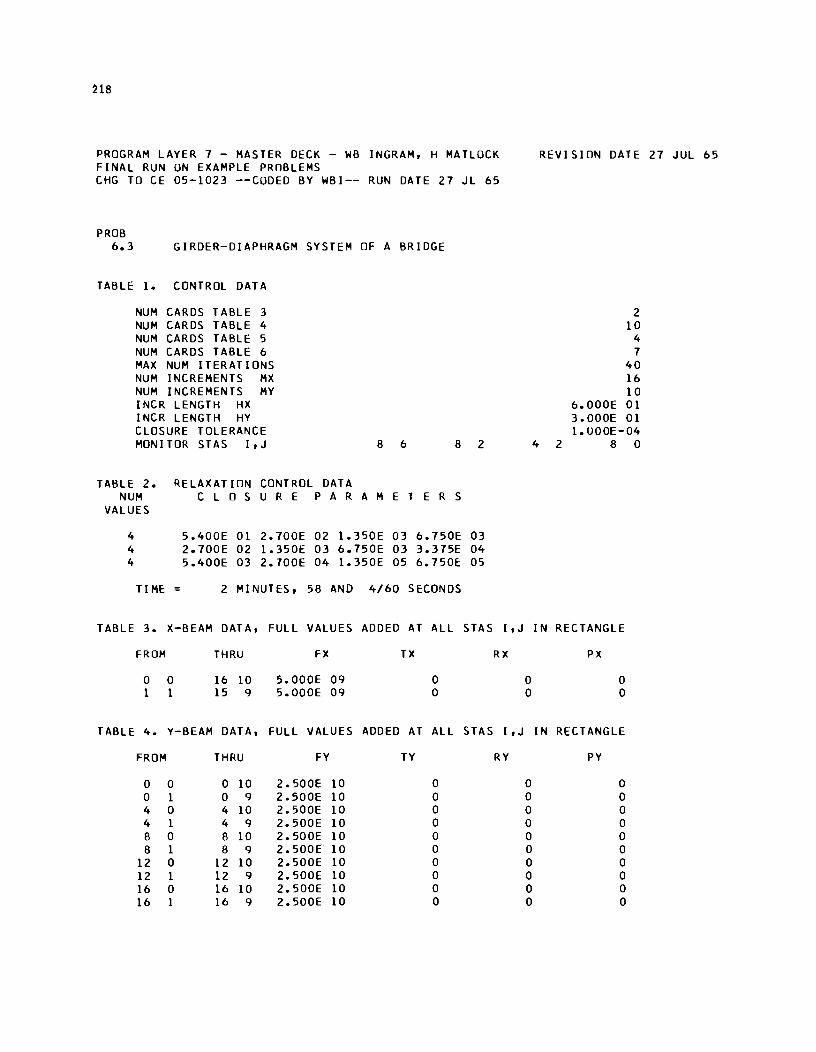
H8
PROGRAM LAYER 7 - MASTER DECK - WB INGRAM, H MATLOCK FINAL RUN ON EXAMPLE PROBLEMS CHG TO CE 05-1023 --CODED BY WBI-- RUN DATE 27 JL 65
PROB 6.3 GIRDER-DIAPHRAGM SYSTEM OF A BRIDGE
TABLE 1. CONTROL DATA
NUM CARDS TABLE 3 NUM CARDS TABLE 4 NUM CARDS TABLE 5 NUM CARDS TABLE 6 MAX NUM ITERATIONS NUM INCREMENTS MX NUM INCREMENTS MY INCR LENGTH HX INCR LENGTH HY CLOSURE TOLERANCE MONITOR STAS I,J 8 6 8 2
TABLE 2. R.ELAXATIDN CONTROL DATA NUM C LOS U R E PAR A M E T E R S
VALUES
4 5.400E 01 2.700E 02 1.350E 03 6.750E 03 4 2.700E 02 1.350E 03 6.750E 03 3.375E 04 4 5.400E 03 2.700E 04 1.350E 05 6.750E 05
TIME: = 2 MINUTES, 58 AND 4/60 SECONDS
TABLE 3. X-BEAM DATA, FULL VALUES ADDED AT ALL STAS I ,J
FROM THRU FX TX RX
0 0 16 10 5.000E 09 0 1 1 15 9 5.000E 09 0
TABLE 4. Y-BEAM DATA, FULL VALUES ADDED AT ALL STAS I ,J
FROM THRU FY TY RY
0 0 0 10 2.500E 10 0 0 1 0 9 2.500E 10 0 4 0 4 10 2.500E 10 0 4 1 4 9 2.500E 10 0 8 0 8 10 2.500E 10 0 8 1 8 9 2.500E 10 0
12 0 12 10 2.500E 10 0 12 1 12 9 2.500E 10 0 16 0 16 10 2.500E 10 0 16 1 16 9 2.500E 10 0
0 0
0 0 0 0 0 0 0 0 0 0
REVISION DATE 27 JUL 65
2 10
4 7
40 16 10
6.000E 01 3.000E 01 1.000E-04
4 2 8 0
IN RECTANGLE
PX
0 0
IN RECTANGLE
PY
0 0 0 0 0 0 0 0 0 0
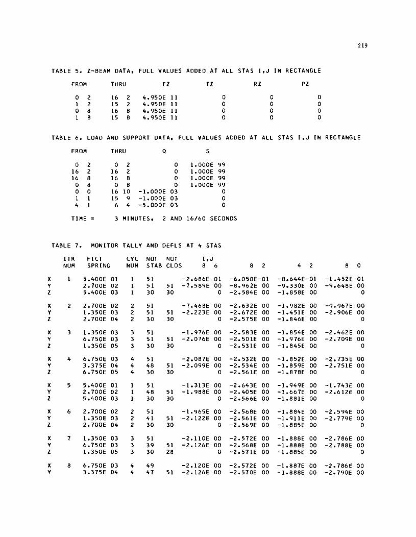
219
TABLE 5. I-BEAM DATA, FULL VALUES ADDED AT ALL STAS I,J IN RECTANGLE
FROM THRU Fl Tl RI PI
0 2 16 2 4.950E 11 0 0 0 1 2 15 2 4.950E 11 0 0 0 0 8 16 8 4.950E 11 0 0 0 1 8 15 8 4.950E 11 0 0 0
TABLE 6. LOAD AND SUPPORT DATA. FULL VALUES ADDED AT ALL STAS I.J IN RECTANGLE
FROM THRU Q S
0 2 0 2 0 1.000E 99 16 2 16 2 0 1.000E 99 16 8 16 8 0 1.000E 99
0 8 0 8 0 1.000E 99 0 0 16 10 -1.000E 03 0 1 1 15 9 -1.000E 03 0 4 1 6 4 -5.000E 03 0
TIME = 3 MINUTES. 2 AND 16/60 SECONDS
TABLE 7. MONITOR TALLY AND DEFLS AT 4 STAS
ITR FICT CYC NOT NOT I. J NUM SPRING NUM STAB CLOS 8 6 8 2 4 2 8 0
X 1 5.400E 01 1 51 -2.686E 01 -6.050E-01 -8.644E-01 -1.452E 01 Y 2.700E 02 1 51 51 -7.589E 00 -8.962E 00 -9.330E 00 -9.648E 00 I 5.400E 03 1 30 30 0 -2.584E 00 -1.858E 00 0
X 2 2.700E 02 2 51 -7.468E 00 -2.632E 00 -1.982E 00 -9.967E 00 Y 1.350E 03 2 51 51 -2.223E 00 -2.672E 00 -1.451E 00 -2.906E 00 I 2.700E 04 2 30 30 0 -2.575E 00 -1.846E 00 0
X 3 1.350E 03 3 51 -1.976E 00 -2.583E 00 -1.854E 00 -2.462E 00 Y 6.750E 03 3 51 51 -2.076E 00 -2.501E 00 -1.976E 00 -2.709E 00 I 1.350E 05 3 30 30 0 -2.531E 00 -1.845E 00 0
X 4 6.750E 03 4 51 -2.087E 00 -2.532E 00 -1.852E 00 -2.735E 00 Y 3.375E 04 4 48 51 -2.099E 00 -2.534E 00 -1.859E 00 -2.751E 00 I 6.750E 05 4 30 30 0 -2.561E 00 -1.878E 00 0
X 5 5.400E 01 1 51 -1.313E 00 -2.643E 00 -1.949E 00 -1.743E 00 Y 2.700E 02 1 48 51 -1.988E 00 -2.405E 00 -1.667E 00 -2.612E 00 I 5.400E 03 1 30 30 0 -2.566E 00 -1.881E 00 0
X 6 2.700E 02 2 51 -1.965E 00 -2.568E 00 -1.884E 00 -2.594E 00 Y 1.350E 03 2 41 51 -2.122E 00 -2.561E 00 -1.911E 00 -2.779E 00 I 2.700E 04 2 30 30 0 -2.569E 00 -1.885E 00 0
X 7 1.350E 03 3 51 -2.110E 00 -2.572E 00 -1.888E 00 -2.786E 00 Y 6.750E 03 3 39 51 -2.126E 00 -2.568E 00 -1.888E 00 -2.788E 00 I 1.350E 05 3 30 28 0 -2.571E 00 -1.885E 00 0
X· 8 6.750E 03 4 49 -2.120E 00 -2.572E 00 -1.881E 00 -2.786E 00 Y 3.375E 04 4 47 51 -2.126E 00 -2.570E 00 -1.888E 00 -2.790E 00
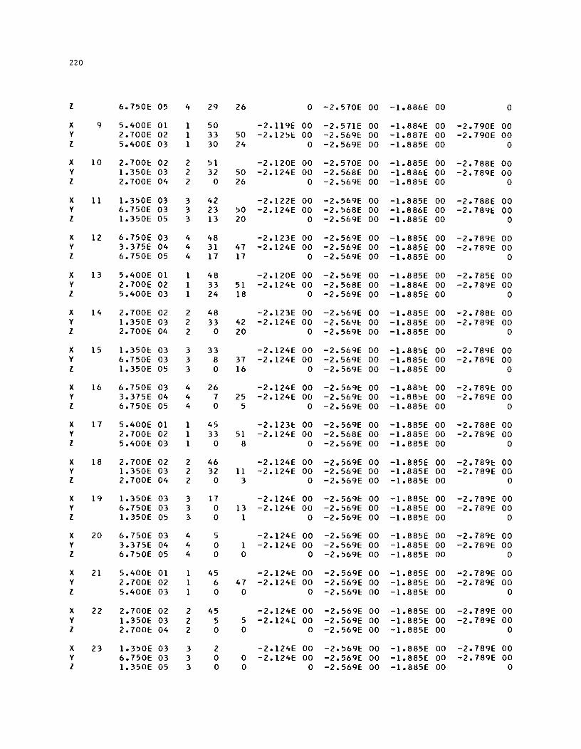
220
l 6.750E 05 4 29 26 0 -2.570E 00 -1.886E 00 0
X 9 5.400E 01 1 50 - 2. 119E 00 -2.571E 00 -1.884E 00 -2. HOE 00 Y 2.700E 02 1 33 50 -2.125E 00 -2.569E 00 -1.887E 00 -2. HOE 00 l 5.400E 03 1 30 24 0 -2.569E 00 -1.885E 00 0
X 10 2.700E 02 2 51 -2.120E 00 -2.570E 00 -1.885E 00 -2.788E 00 Y 1.350E 03 2 32 50 -2.124E 00 -2.568E 00 -1.886E 00 -2.789E 00 l 2.700E 04 2 0 26 0 -2.569E 00 -1.885E 00 0
X 11 1.350E 03 3 42 -2.122E 00 -2.569E 00 -1.885E 00 -2.788E 00 Y 6.750E 03 3 23 50 -2.124E 00 -2.568E 00 -1.886E 00 -2.789E: 00 l 1.350E 05 3 13 20 0 -2.569E 00 -1.885E 00 0
X 12 6.750E 03 4 48 -2.123E 00 -2.569E 00 -1.885E 00 -2.789E 00 Y 3.375E 04 4 31 47 -2.124E 00 -2.569E 00 -1.885E 00 -2.789E 00 l 6.750E 05 4 17 17 0 -2.569E 00 -1.885E 00 0
X 13 5.400E 01 1 48 -2.120E 00 -2.569E 00 -1.885E 00 -2.785E 00 Y 2.700E 02 1 33 51 -2.124E 00 -2.568E 00 -1.884E 00 -2.789E 00 l 5.400E 03 1 24 18 0 -2.569E 00 -1.885E 00 0
X 14 2.700E 02 2 48 -2.123E 00 -2.569E 00 -I.885E 00 -2.788E 00 Y 1.350E 03 2 33 42 -2.124E 00 -2.569E 00 -1.885E 00 -2.789E 00 l 2.700E 04 2 0 20 0 -2.569E 00 -1.885E 00 0
X 15 1.350E 03 3 33 -2.124E 00 -2.569E 00 -1.885E 00 -2.789E 00 Y 6.750E 03 3 8 37 -2.124E 00 -2.569E 00 -1.885E 00 -2.789E 00 l 1.350E 05 3 0 16 0 -2.569E 00 -1.885E 00 0
X 16 6.750E 03 4 26 -2.124E 00 -2.569E 00 -I.885E 00 -2.789E 00 Y 3.375E 04 4 7 25 -2.124E 00 -2.569E 00 -1.885E 00 -2.789E 00 l 6.750E 05 4 0 5 0 -2.569E 00 -1.885E 00 0
X 17 5.400E 01 1 45 -2.123E 00 -2.569E 00 -I.885E 00 -2.788E 00 Y 2.700E 02 1 33 51 -2.124E 00 -2.568E 00 -1.885E 00 -2.789E 00 l 5.400E 03 1 0 8 0 -2.569E 00 -1.885E 00 0
X 18 2.700E 02 2 46 -2.124E 00 -2.569E 00 -1.885E 00 -2.789E 00 Y 1.350E 03 2 32 11 -2.124E 00 -2.569E 00 -1.885E 00 -2.789E 00 l 2.700E 04 2 0 3 0 -2.569E 00 -1.885E 00 0
X 19 1.350E 03 3 17 -2.124E 00 -2.569E 00 -1.885E 00 -2.789E 00 Y 6.750E 03 3 0 13 -2.124E OU -2.569E 00 -1.885E 00 -2.789E 00 l 1.350E 05 3- 0 1 0 -2.569E 00 -1.885E 00 0
X 20 6.750E 03 4 5 -2.124E 00 -2.569E 00 -1.885E 00 -2.789E 00 Y 3.375E 04 4 0 I -2.124E 00 -2.569E 00 -1.885E 00 -2.789E 00 l 6.750E 05 4 0 0 0 -2.569E 00 -1.885E 00 0
X 21 5.400E 01 1 45 -2.124E 00 -2.569E 00 -1.885E 00 -2.789E 00 Y 2.700E 02 1 6 47 -2.124E 00 -2.569E 00 -1.885E 00 -2.789E 00 l 5.400E 03 1 0 0 0 -2.569E 00 -1.885E 00 0
X 22 2.700E 02 2 45 -2.124E 00 -2.569E 00 -1.885E 00 -2.789E 00 Y 1.350E 03 2 5 5 -2.124E 00 -2.569E 00 -1.885E 00 -2.789E 00 l 2.700E 04 2 0 0 0 -2.569E 00 -1.885E 00 0
X 23 1.350E 03 3 2 -2.124E 00 -2.569E 00 -1.885E 00 -2.789E 00 Y 6.750E 03 3 0 0 -2.I24E 00 -2.569E 00 -1.885E 00 -2.789E 00 l 1.350E 05 3 0 0 0 -2.569E 00 -1.8S5E 00 0
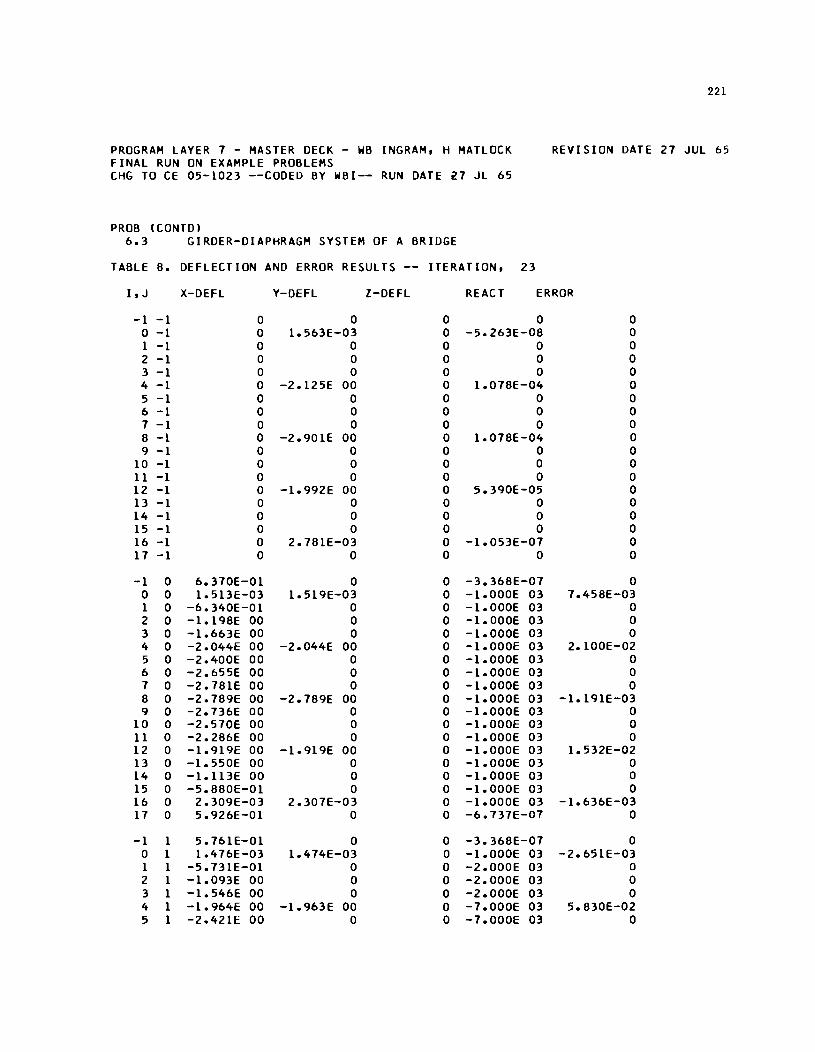
PROGRAM LAYER 7 - MASTER DECK - WB INGRAM, H MATLOCK FINAL RUN ON EXAMPLE PROBLEMS CHG TO CE 05-1023 --CODED BY WBI-- RUN DATE ~7 JL 65
PROB (CONTOI 6.3 GIRDER-DIAPHRAGM SYSTEM OF A BRIDGE
TABLE 6. DEFLECTION AND ERROR RESULTS -- ITERATION,
221
REVISION DATE 27 JUL 65
23
I, J X-DEFL Y-DEFL l-DEFL REACT ERROR
-1 -1 0 0 0 0 0 0 -1 0 1.563E-03 0 -5.263E-06 0 1 -1 0 0 0 0 0 2 -1 0 0 0 0 0 3 -1 0 0 0 0 0 4 -1 0 -2.125E 00 0 1.076E-04 0 5 -1 0 0 0 0 0 6 -1 0 0 0 0 0 7 -1 0 0 0 0 0 6 -1 0 -2.901E 00 0 1.076E-04 0 9 -1 0 0 0 0 0
10 -1 0 0 0 0 0 11 -1 0 0 0 0 0 12 -1 0 -1.992E 00 0 5.390E-05 0 13 -1 0 0 0 0 0 14 -1 0 0 0 0 0 15 -1 0 0 0 0 0 16 -1 0 2.761E-03 0 -1.053E-07 0 17 -1 0 0 0 0 0
-1 0 6.370E-01 0 0 -3.366E-07 0 0 0 1.513E-03 1.519E-03 0 -1.000E 03 7.456E-03 1 0 -6.340E-01 0 0 -1.000E 03 0 2 0 -1.196E 00 0 0 -1.000E 03 0 3 0 -1.663E 00 0 0 -1.000E 03 0 4 0 -2.044E 00 -2.044E 00 0 -1.000E 03 2.100E-02 5 0 -2.400E 00 0 0 -1.000E 03 0 6 0 -2.655E 00 0 0 -1.000E 03 0 7 0 -2.761E 00 0 0 -1.000E 03 0 6 0 -2.769E 00 -2.769E 00 0 -1.000E 03 -1.191E-03 9 0 -2.736E 00 0 0 -1.000E 03 0
10 0 -2.570E 00 0 0 -1.000E 03 0 11 0 -2.266E 00 0 0 -1.000E 03 0 12 0 -1.919E 00 -1.919E 00 0 -1.000E 03 1.532E-02 13 0 -1.550E 00 0 0 -1.000E 03 0 14 0 -1.113E 00 0 0 -1.000E 03 0 15 0 -5.660E-01 0 0 -1.000E 03 0 16 0 2.309E-03 2.307E-03 0 -1.000E 03 -1.636E-03 17 0 5.926E-01 0 0 -6.737E-07 0
-1 1 5.761E-01 0 0 -3.366E-07 0 0 1 1.476E-03 1.474E-03 0 -1.000E 03 -2.651E-03 1 1 -5.731E-01 0 0 -2.000E 03 0 2 1 -1.093E 00 0 0 -2.000E 03 0 3 1 -1.546E 00 0 0 -2.000E 03 0 4 1 -1.964E 00 -1.963E 00 0 -7.000E 03 5.630E-02 5 1 -2.421E 00 0 0 -7.000E 03 0
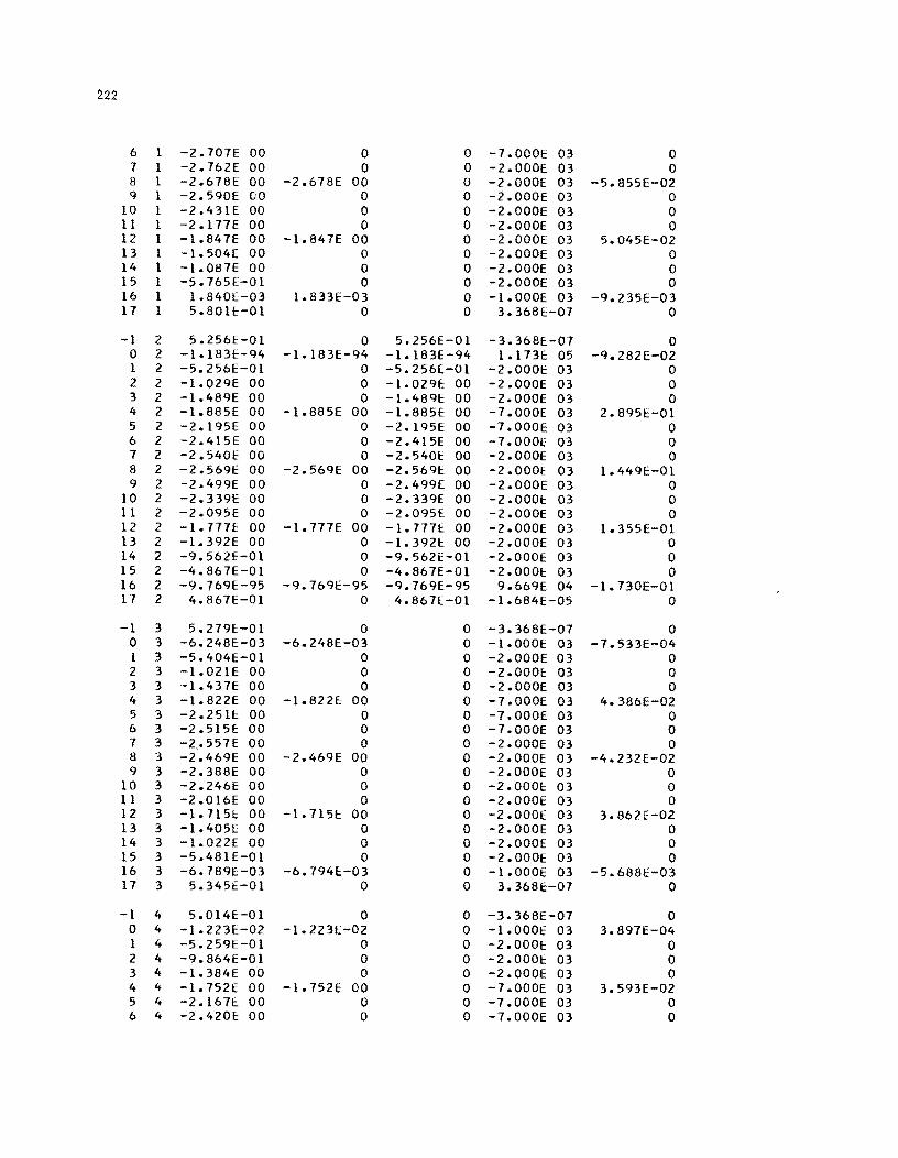
222
6 1 -2.101E 00 0 0 -1.000E 03 0 1 1 -2.162E 00 0 0 -2.000E 03 0 8 1 -2.618E 00 -2.618E 00 0 -2.000E 03 -5.855E-02 9 1 -2.590E 00 0 0 -i.OOOE 03 0
10 1 -2.431E 00 0 0 -2.000E 03 0 11 1 -2.111E 00 0 0 -2.000E 03 0 12 1 -1.841E 00 -1.841E 00 0 -2.000E 03 5.045E-02 13 1 -1.504[ 00 0 0 -2.000E 03 0 14 1 -1.081E 00 0 0 -2.000E 03 0 15 1 -5.165E-Ol 0 0 -2.000E 03 0 16 1 1.840E-03 1.833E-03 0 -1.000E 03 -9.235E-03 11 1 5.8011::-01 0 0 3.368E-01 0
-1 2 5.256E-01 0 5.256E-01 -3.368E-01 0 0 2 -1.183E-94 -1.183E-94 -1.183E-94 1.113E 05 -9.282E-02 1 2 -5.256E-Ol 0 -5.256£-01 -2.0001: 03 0 2 2 -1.029E 00 0 -1.029E 00 -2.000E 03 0 3 2 -1.489E 00 0 -1.489E 00 -2.000E 03 0 4 2 -1.885E 00 -I.885E 00 -1.885E 00 -1. OOOE 03 2.8951::-01 5 2 -2.195E 00 0 -2.195E 00 -1.OOOE 03 0 6 2 -2.415E 00 0 -2.415E 00 -1.0001:' 03 0 1 2 -2.540E 00 0 -2.5401:: 00 -2.000E 03 0 8 2 -2.569E 00 -2.569E 00 -2.569E 00 -2.000E 03 1.449E-Ol 9 2 -2.499E 00 0 -2.499E 00 -2.000E 03 0
10 2 -2.3391: 00 0 -2.339E 00 -2.0001:: 03 0 11 2 -2.095E 00 0 -2.0951:: 00 -2.000E 03 0 12 2 -l.11IE 00 -1.111E 00 -1.111f::. 00 -2.000E 03 1.355E-Ol 13 2 -1.392E 00 0 -1.3921:: 00 -2.000E 03 0 14 2 -9.5621"-01 0 -9.562£-01 -2.000E 03 0 15 2 -4.861E-Ol 0 -4.861E-Ol -2.000E 03 0 16 2 -9.769E-95 -9.169E-95 -9.169E-95 9.669E 04 -1.130E-01 11 2 4.861E-Ol 0 4.861[-01 -1.684E-05 0
-1 3 5.279E:-Ol 0 0 -3.368E-01 0 0 3 -6.248E-03 -6.248E-03 0 -1.000E 03 -1.533E-04 1 3 -5.404E-Ol 0 0 -2.000E 03 0 2 3 -1.021E 00 0 0 -2.000£: 03 0 3 3 -1.431E 00 0 0 -2.000E 03 0 4 3 -1.822E 00 -1.822E 00 0 -1.000E 03 4.386E-02 5 3 -2.251E 00 0 0 -1.000E 03 0 6 3 -2.515!: 00 0 0 -1.000E 03 0 1 3 -2 .• 551E 00 0 0 -2.000E 03 0 8 3 -2.469E 00 -2.469E 00 0 -2.000E 03 -4.232E-02 9 3 -2.388E 00 0 0 -2.000E 03 0
10 3 -2.246E 00 0 0 -2.000E 03 0 11 3 -2.016E 00 0 0 -2.000E 03 0 12 3 -1.115E 00 -1.115E 00 0 -2.000E 03 3.862E-02 13 3 -1.405E 00 0 0 -2.000E 03 0 14 3 -1.022E 00 0 0 -2.000E 03 0 15 3 -5.481E-01 0 0 -2.000E 03 0 16 3 -6.189E-03 -6.194E-03 0 -l.OOOE 03 -5.688E-03 l1 3 5.345E-Ol 0 0 3.368E-01 0
-1 4 5.014E:-01 0 0 -3.368E-01 0 0 4 -1.223E:-02 -1.223[-02 0 -1.000E 03 3.891E-04 1 4 -5.259E-Ol 0 0 -2.000E 03 0 2 4 -9.864E-Ol 0 0 -2.0001:: 03 0 3 4 -1.384E 00 0 0 -2.000E 03 0 4 4 -1.752E 00 -1.752E 00 0 -1.000E 03 3.593E-02 5 4 -2.161E:. 00 0 0 -1.000E 03 0 6 4 -2.420E 00 0 0 -1.000E 03 0
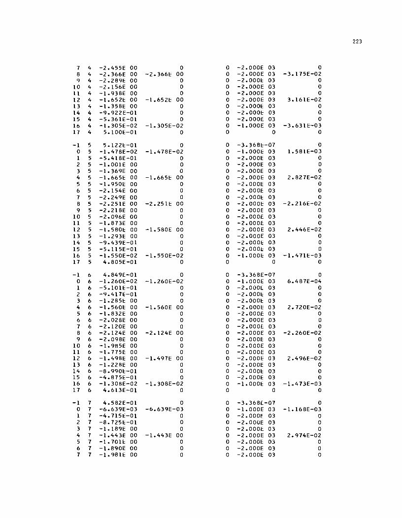
223
7 4 -2.455E 00 0 0 -2.000E 03 0 8 4 -2.366E 00 -2.366E 00 0 -2.000E 03 -3.175E-02 9 4 -2.289E 00 0 0 -2.0001: 03 0
10 4 -2.156E 00 0 0 -2.000E 03 0 11 4 -1.938E 00 0 0 -2.000E 03 0 12 4 -1.652E 00 -1.652E 00 0 -2.000E 03 3.161E-02 13 4 -1.358E 00 0 0 -2.000E 03 0 14 4 -9.922E-01 0 0 -2.000E 03 0 15 4 -5.361E-01 0 0 -2.000E 03 0 16 4 -1.305E-02 -1.305E-02 0 -1.000E 03 -3.631E-03 17 4 5.100E-01 0 0 0 0
-1 5 5.122E-01 0 0 -3.368E-07 0 0 5 -1.478E-02 -1.478E-02 0 -1.000E 03 1.581E-03 1 5 -5.418E-01 0 0 -2.000E 03 0 2 5 -1.001E 00 0 0 -2.000E 03 0 3 5 -1.369E 00 0 0 -2.000E 03 0 4 5 -1.665E 00 -1.665E 00 0 -2.000E 03 2.827E-02 5 5 -1.950E 00 0 0 -2.000E 03 0 6 5 -2.154E 00 0 0 -2.0001: 03 0 7 5 -2.249E 00 0 0 -2.000E 03 0 8 5 -2.251E 00 -2.251E 00 0 -2.000E 03 -2.216E-02 9 5 -2.218E 00 0 0 -2.000E 03 0
10 5 -2.096E 00 0 0 -2.000E 03 0 11 5 -1.873E 00 0 0 -2.0001: 03 0 12 5 -1.580E 00 -1.580E 00 0 -2.000E 03 2.446E-02 13 5 -1.293E 00 0 0 -2.000E 03 0 14 5 -9.439E-01 0 0 -2.000E 03 0 15 5 -5.115E-01 0 0 -2.0001: 03 0 16 5 -1.550E-02 -1.550E-02 0 -1.000E 03 -1.471E-03 17 5 4.805E-01 0 0 0 0
-1 6 4.849E-01 0 0 -3.368E-07 0 0 6 -1.260E-02 -1.260E-02 0 -1.000E 03 6.487E-04 1 6 -5.101E-01 0 0 -2.000E 03 0 2 6 -9.417E-01 0 0 -2.000E 03 0 3 6 -1.285E 00 0 0 -2.000E 03 0 4 6 -1.560E 00 -1.560E 00 0 -2.000E 03 2.720E-02 5 6 -1.832E 00 0 0 -2.000E 03 0 6 6 -2.028E 00 0 0 -2.000E 03 0 7 6 -2.120E 00 0 0 -2.0001: 03 0 8 6 -2.124E 00 -2.124E 00 0 -2.000E 03 -2.260E-02 9 6 -2.098E 00 0 0 -2.0001: 03 0
10 6 -1.985E 00 0 0 -2.000E 03 0 11 6 -1.775E 00 0 0 -2.0001: 03 0 12 6 -1.498E 00 -1.497E 00 0 -2.000E 03 2.496E-02 13 6 -1.228E 00 0 0 -2.000E 03 0 14 6 -8.990E-01 0 0 -2.000E 03 0 15 6 -4.875E-01 0 0 -2.000E 03 0 16 6 -1.308E-02 -1.308E-02 0 -1.000E 03 -1.473E-03 17 6 4.613E-01 0 0 0 0
-1 7 4.582E-01 0 0 -3.3681:-07 0 0 7 -6.639E-03 -6.639E-03 0 -1.000E 03 -1.168E-03 1 7 -4.715E-01 0 0 -2.000E 03 0 2 7 -8.725E-01 0 0 -2.000E 03 0 3 7 -1.189E 00 0 0 -2.0001: 03 0 4 7 -1.443E 00 -1.443E 00 0 -2.000E 03 2.974E-02 5 7 -1.7011: 00 0 0 -2.0001: 03 0 6 7 -1.890E 00 0 0 -2.000E 03 0 7 7 -1.981E 00 0 0 -2.000E 03 0
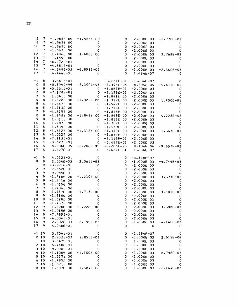
224
8 7 -1.988E 00 -1.988E 00 0 -2.000E 03 -2.770E-02 9 7 -1.9671:: 00 0 0 -2.000E 03 0
10 7 -1.865[ 00 0 0 -2.000E 03 0 11 7 -1.667£ 00 0 0 -2.000E 03 0 12 7 -1.4061::. 00 -1.406E 00 0 -2.0001::: 03 2.768E-02 13 7 -1.155E 00 0 0 -2.0001::: 03 0 14 7 -8.472L-Ol 0 0 -2.000E 03 0 15 7 -4.581E-Ol 0 0 -2.000E 03 0 16 7 -6.849E-03 -6.851E-03 0 -1.0001:: 03 -2.360E-03 17 7 4.4441:-01 0 0 1.6841::-07 0
-1 8 3.66lE-01 0 3.6611::-01 -1.684E-07 0 0 8 -8.394[-95 -8.394E-95 -8.394E-95 8.2941::: 04 -9.411E-02 1 8 -3.6611::-01 0 -3.6611:::-01 -2.0001: 03 0 2 8 -7.1781::-01 0 -7.1781::-01 -2.000£ 03 0 3 8 -1.041E 00 0 -1.0411:: 00 -2.0001:: 03 0 4 8 -1.32L'l: 00 -1.322E 00 -1.322E 00 -2.000E 03 1.450E-Ol 5 8 -1.547E 00 0 -1.547E 00 -2.0001:: 03 0 6 8 -1.713£ 00 0 -1.7131:: 00 -2.0001:: 03 0 7 8 -1.815E 00 0 -1.815E 00 -2.0001:: 03 0 8 8 -1.848£ 00 -1.848E 00 -1.848E 00 -2.000E: 03 9.2?2E-02 9 8 -l.g11E: 00 0 -1.811E 00 -2.0001:: 03 0
10 8 -1.707l 00 0 -1.707E 00 -2.000E: 03 0 11 8 -1.539E: 00 0 -1.539E 00 -2.000E 03 0 12 8 -1.3121:: 00 -1.3121: 00 -1.312E: 00 -2.000E 03 1.343E-Ol 13 8 -1.032F 00 0 -1.032E 00 -2.0001::: 03 0 14 8 -7.113[-01 0 -7.113E-Ol -2.000E 03 0 15 8 -3.627E-Ol 0 -3.627E-Ol -2.000E 03 0 16 8 -8.2061::.-95 -8.2061:::-95 -8.206E-95 8.106E 04 -9.637E-02 17 8 3.627E-Ol 0 3.627E-Ol -1.684E-07 0
-1 9 4.012E:-Ol 0 0 -3.368E-07 0 0 9 2.064E-03 2.061E-03 0 -1.000E 03 -4.744E-03 1 9 -3.971E-Ol 0 0 -2.0001:: 03 0 2 9 -7.362E-Ol 0 0 -2.0001::: 03 0 3 9 -9.9841::-01 0 0 -2.000E 03 0 4 9 -1.7101:: 00 -1.210£ 00 0 -2.000E 03 3.373E-02 5 9 -1.441E 00 0 0 -2.0001:: 03 0 6 9 -1.6151: 00 0 0 -2.0001::. 03 0 7 9 -1.704£ 00 0 0 -2.000E 03 0 8 9 -1.717E 00 -1.717E 00 0 -2.000E 03 -3.8011::-02 9 9 -1.7101:: 00 0 0 -2.000E 03 0
10 9 -1.628E 00 0 0 -2.000[ 03 0 11 9 -1.4571:: 00 0 0 -2.000E 03 0 12 9 -1.228E 00 -1.2281:: 00 0 -2.000E 03 3.398E-02 13 9 -1.015E 00 0 0 -2.000E 03 0 14 9 -7. 485E-0 1 0 0 -2.000[ 03 0 15 9 -4.0361:'-01 0 0 -2.000E 03 0 16 9 2.202[-03 2.199E-03 0 -1.000f: 03 -4.140E-03 17 9 4.0801::-01 0 0 0 0
-1 10 3.7041::-01 0 0 -1.684E-07 0 0 10 2.8521::.-03 2.853E-03 0 -1.000E: 03 2.019E-04 1 10 -3.647f-Ol 0 0 -1.0001::: 03 0 2 10 -6.7401:-01 0 0 -1.0001:: 03 0 3 10 -C).098t-Ol 0 0 -1.0001:: 03 0 4 10 -1.1001:: 00 -1.100E 00 0 -1.000l: 03 8.798E-03 5 10 -1.3171:: 00 0 0 -1.0001:: 03 0 6 10 -1.485E 00 0 0 -1.0001:: 03 0 7 10 -1.5711:: 00 0 0 -1.000E 03 0 8 10 -1.587r 00 -1.5871: 00 0 -1.000E 03 -2.1641::-03
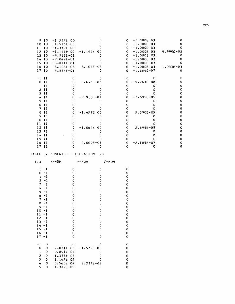
225
9 10 -1.587L 00 0 0 -1. 000t' 03 0 10 10 -1.5161:: 00 0 0 -1.000t 03 0 11 10 -1.3591:: 00 0 0 -1.0001:: 03 0 12 10 -1.146E 00 -1.1461:: 00 0 -1.000E 03 9.990E-03 13 10 -9.512[-01 0 0 -1.000E 03 0 14 10 -7.0491::-01 0 0 -1.0001:: 03 0 15 10 -3.811E-Ol 0 0 -1.000E 03 0 16 10 3.103L-03 3.104E-03 0 -1.000E 03 1.9331::-03 17 10 3.873E-Ol 0 0 -1.684E-07 0
-1 11 0 0 0 0 0 0 11 0 3.6451::-03 0 -5.263E-08 0 1 11 0 0 0 0 0 2 11 0 0 0 0 0 3 11 0 0 0 0 0 4 11 0 -9.9101::-01 0 -2.6951::-05 0 5 11 0 0 0 0 0 6 11 0 0 0 0 0 7 11 0 0 0 0 0 8 11 0 -1.457E 00 0 5.390E-05 0 9 11 0 0 0 0 0
10 11 0 0 0 0 0 11 11 0 0 0 0 0 12 11 0 -1.064E 00 0 2.695[-05 0 13 11 0 0 0 0 0 14 11 0 0 0 0 0 15 11 0 0 0 0 0 16 11 0 4.009E-03 0 -2.105E-07 0 17 11 0 0 0 0 0
TABLE 9. MOMENTS ITERATION 23
I, J X-MOM V-MOM l-MOM
-1 -1 0 0 0 0 -1 0 0 0 1 -1 0 0 0 2 -1 0 0 0 3 -1 0 0 0 4 -1 0 0 0 5 -1 0 0 0 6 -1 0 0 0 7 -1 0 0 0 8 -1 0 0 0 9 -1 0 0 0
10 -1 0 0 0 11 -1 0 0 0 12 -1 0 0 0 13 -1 0 0 0 14 -1 0 0 0 15 -1 0 0 0 16 -1 0 0 0 17 -1 0 0 0
-1 0 0 0 0 0 0 -2.0211.:-05 -1.579E-06 0 1 0 9.891[ 04 0 0 2 0 1.378E 05 0 0 3 0 1.1671:: 05 0 0 4 0 3.5631:: 04 3.234E-03 0 5 0 1. 3821:. 05 0 0
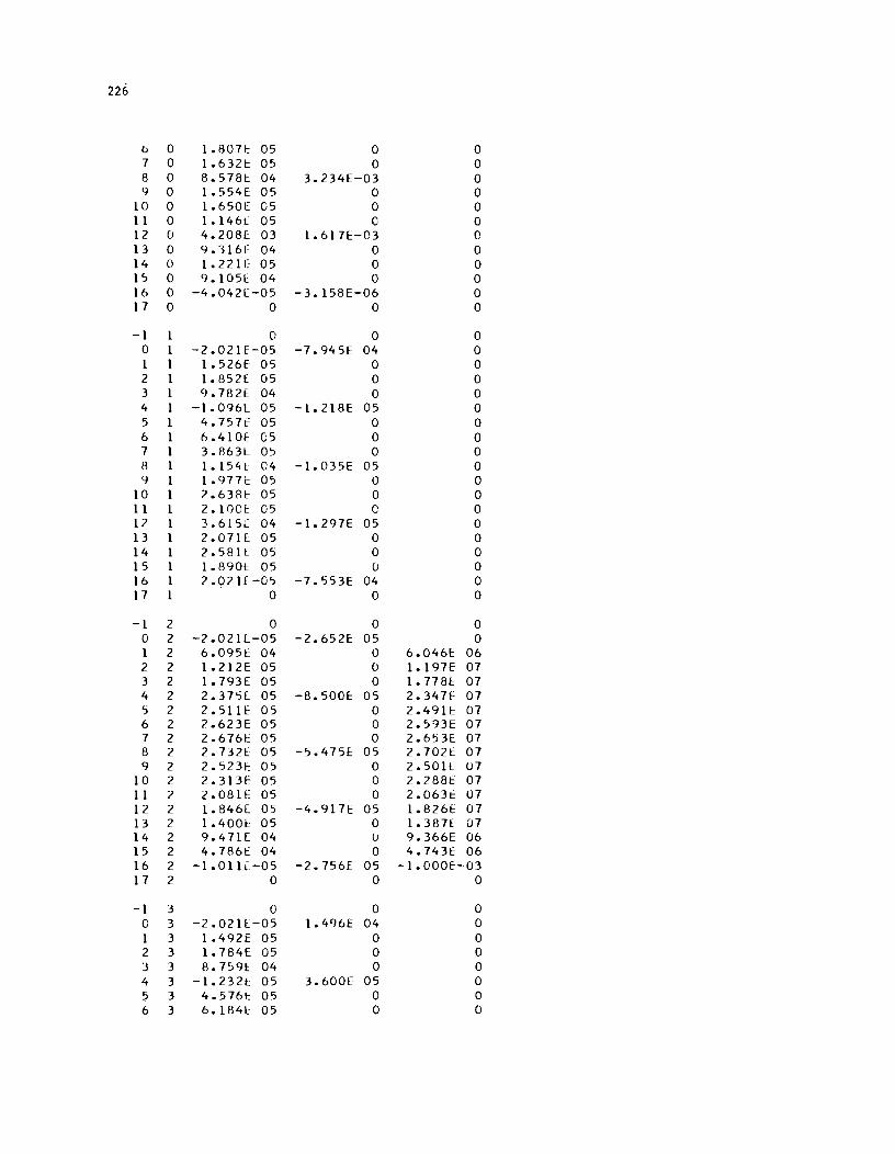
226
b 0 1.8071: 05 0 0 7 0 1.632t: 05 0 0 8 0 8.578t 04 3.234E-03 0 '} 0 1.554E 05 0 0
10 0 1.6501: 05 0 0 11 0 1.1461:' 05 0 0 12 (J 4.208[: 03 1.617E-03 0 13 0 9.316[: 04 0 0 14 0 1.221E 05 0 0 1~ 0 9.105[ 04 0 0 16 0 -4.042[-05 -3.158E-06 0 17 0 0 0 0
-1 1 [I 0 0 0 1 -2.021E-05 -7.945E 04 0 1 1 1.526E 05 0 0 2 1 1.852E: 05 0 0 3 1 9.782E: 04 0 0 4 1 -1.096L 05 -1.218E 05 0 5 1 4.757t' 05 0 0 6 1 6.4101: 05 0 0 7 1 3.863t 05 0 0 8 1 1.154[ 04 -1.035E 05 0 9 1 1.977't. O~ 0 0
10 1 2.63Rf 05 0 0 1 1 1 2.100E: 05 C 0 12 1 3.615'-- 04 -1.297E 05 0 13 1 2.071E: 05 0 0 14 1 2.581E 05 0 0 15 1 1.890t 05 Q 0 16 1 2 .02lE -05 -7.553E 04 0 17 1 0 0 0
-1 2 0 0 0 0 2 -2.021£:-05 -2.652E: 05 0 1 2 6.095t 04 0 6.046E: 06 2 2 1.212E 05 (J 1.197E 07 3 2 1.793E 05 0 1.77 8f: 07 4 2 2.375E: 05 -8.500E: 05 2.347E 07 5 2 2.51lE 05 0 2.491E: 07 6 2 2.623E 05 0 2.~93E 07 7 2 2.6761: 05 0 2.653E 07 8 2 2.7321::: 05 -5.475E 05 2.7021:' 07 9 2 2.5231: 05 0 2.50lt 07
10 2 2.313E 05 0 2.288t 07 11 2 2.0811: 05 0 2.063t 07 12 2 1.846E 05 -4.917E 05 1.826E: 07 13 2 1.4001::: 05 0 1.38n 07 14 2 9.471E 04 () 9.366E 06 15 2 4.7861: 04 0 4.743t 06 16 2 -1.011t-05 -2.756E 05 -1.000E-03 17 2 0 0 0
-1 3 0 0 0 0 3 -2.02 U. -05 1.4%E 04 0 1 3 1.492E 05 0 0 2 3 1.784E 05 0 0 3 3 8.7591::: 04 0 0 4 3 -1.232t 05 3.600f 05 0 5 3 4.5761::: 05 0 0 6 3 6.184[ 05 0 0
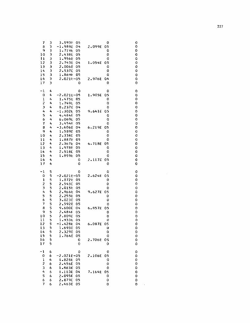
227
7 3 3.593E 05 0 0 8 3 -1.989E 04 2.099E 05 0 9 3 1.7191.: 05 0 0
10 3 2.438E 05 0 0 11 3 1.956E 05 0 0 12 3 2.743E 04 1.054E 05 0 13 3 2.006E 05 0 0 14 3 2.537E 05 0 0 15 3 1.869E 05 0 0 16 3 2.021E-05 2.976E 04 0 17 3 0 0 0
-1 4 0 0 0 0 4 -2.021E-05 1.905E 05 0 1 4 1.475E 05 0 0 2 4 1.7491;. 05 0 0 3 4 8.237E 04 0 0 4 4 -1.3021.: 05 9.641E 05 0 5 4 4.484E 05 0 0 6 4 6.069E 05 0 0 7 4 3.454E 05 0 0 8 4 -3.606E 04 6.219E 05 0 9 4 1.589E 05 0 0
10 4 2.338E 05 0 0 11 4 1.887E 05 0 0 12 4 2.367E: 04 4.7l8E 05 0 13 4 1.978E 05 0 0 14 4 2.518[ 05 0 0 15 4 1.8591.: 05 0 0 16 4 0 2.11 7E 05 0 17 4 0 0 0
-1 5 0 0 0 0 5 -2.021E-05 2.624E 05 0 1 5 1.872E 05 0 0 2 5 2.543[ 05 0 0 3 5 2.015E 05 0 0 4 5 2.866E 04 9.627E 05 0 5 5 2.2551.: 05 0 0 6 5 3.0231.: 05 0 0 7 5 2.592E 05 0 0 8 5 9.600E 04 6.857E 05 0 9 5 2.484E 05 0 0
10 5 2.809[ 05 0 0 11 5 1.933E 05 0 0 12 5 -1.428E: 04 6.087E 05 0 13 5 1.693E 05 0 0 14 5 2.329E 05 0 0 15 5 1.764E 05 0 0 16 5 0 2.706E 05 0 17 5 0 0 0
-1 6 0 0 0 0 6 -2.021E-05 2.106E 05 0 1 6 1.828E 05 0 0 2 6 2.456E 05 0 0 3 6 1.683E 05 0 0 4 6 i.ll0E 04 7.164E 05 0 5 6 2.095E 05 0 0 6 6 2.879[ 05 0 0 7 6 2.463E 05 0 0
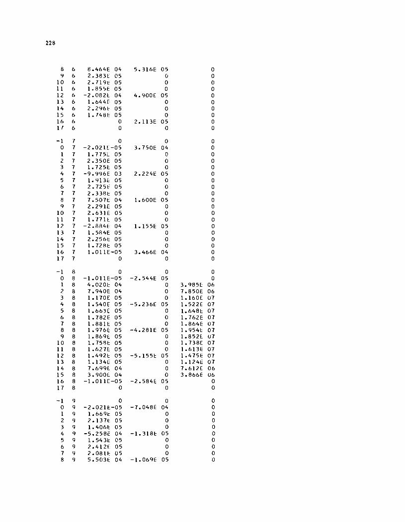
228
8 6 8.464E 04 5.316E 05 0 9 6 2.383E 05 0 0
10 6 2.719t: 05 0 0 11 6 1.85'>1' 05 0 0 12 6 -2.0821: 04 4.900E 05 0 13 6 1.6441' 05 0 0 14 6 2.29M: 05 0 0 15 6 1.748E 05 0 0 16 6 0 2.113E 05 0 17 6 0 0 0
-1 7 0 0 0 0 7 -2.021E-05 3.750E 04 0 1 7 1.775E 05 0 0 2 7 2.350E 05 0 0 3 7 1.7251' 05 0 0 4 7 -9.996E 03 2.224E 05 0 5 7 1.913E 05 0 0 6 7 2.72SE 05 0 0 7 7 2.338f: 05 0 0 8 7 7. 50n: 04 1.600E 05 0 9 7 2.2911' 05 0 0
10 7 2.631E 05 0 0 11 7 1.n1l 05 0 0 12 7 -2.884E 04 1.155E 05 0 13 7 1.584E 05 0 0 14 7 2.256E 05 0 0 15 7 1.728f: 05 0 0 1& 7 1.011E-05 3.466E 04 0 17 7 0 0 0
-1 8 0 0 0 0 8 -1.011E-05 -2.544E 05 0 1 8 4.0201' 04 0 3.985[ 06 2 8 7.940E 04 0 7.850E 06 3 8 1.170E 05 0 1.160E U7 4 8 1.540E 05 -5.236E 05 1.522E 07 5 8 1.663E 05 0 1.648E 07 6 8 1.782E 05 0 1.762E 07 7 8 1.881E 05 0 1.864E 07 8 8 1.976E 05 -4.281E 05 1.9541: 07 <} 8 1. 8691: 05 0 1.8521: U7
10 8 1.7581: 05 0 1.738E 07 11 8 1.6271 05 0 1.6l3E 07 12 8 1.492E 05 -5.155E 05 1.475E 07 13 8 1.l34[ 05 0 1.124E 07 14 8 7.699E: 04 0 7.612E 06 15 8 3.900E 04 0 3.866E U6 16 8 -1.011E-05 -2.584E 05 0 17 8 0 0 0
-1 9 0 0 0 0 9 -2.021E-05 -7.048E 04 0 1 9 1.6691: 05 0 0 2 9 2.1371: 05 0 0 3 9 1.406!:: 05 0 0 4 9 -5.258E 04 -1.318E 05 0 5 9 1. 5431: 05 0 0 6 9 2.412E 05 0 0 7 9 2.0811:: 05 0 0 8 9 5.503E 04 -1.069E 05 0
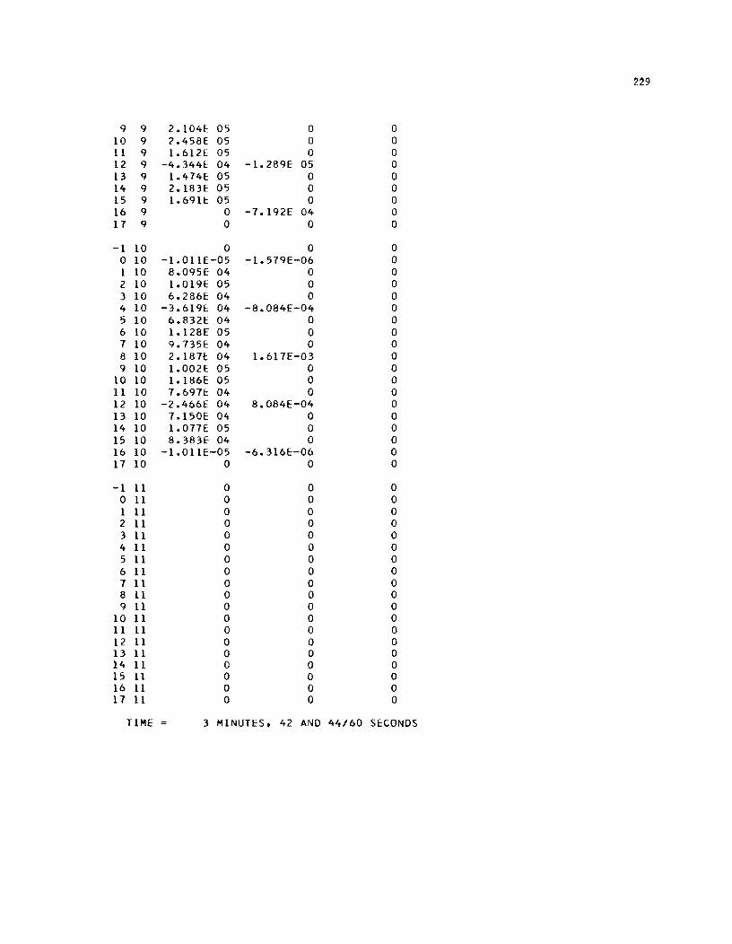
2~9
9 9 2.1041: 05 0 0 10 9 2.458E 05 0 0 11 9 1.61ZE 05 0 0 12 9 -4.344E 04 -1.289E 05 0 13 9 1.414E 05 0 0 14 9 2.183F 05 0 0 15 9 1.691t 05 0 0 16 9 0 -7.192E 04 0 17 9 0 0 0
-1 10 0 0 0 0 10 -1.0llE-05 -1.519E-06 0 1 10 8.095E 04 0 0 2 10 1.019E 05 0 0 3 10 6.286E 04 0 0 4 10 -3.6191:: 04 -8.084E-04 0 5 10 6.8321: 04 0 0 6 10 1.128E 05 0 0 7 10 9.735E 04 0 0 8 10 2.1871: 04 1.617E-03 0 9 10 1.002E 05 0 0
10 10 1.186E 05 0 0 11 10 1.691f: 04 0 0 12 10 -2.466E 04 8.084E-04 0 13 10 7.150E 04 0 0 14 10 1.017E 05 0 0 15 10 8.383E 04 0 0 16 10 -l.01lE-05 -6.316E-06 0 17 10 0 0 0
-1 11 0 0 0 0 11 0 0 0 1 11 0 0 0 2 11 0 0 0 3 11 0 0 0 4 11 0 0 0 5 11 0 0 0 6 11 0 0 0 7 11 0 0 0 8 11 0 0 0 9 11 0 0 0
10 11 0 0 0 11 11 0 0 0 12 11 0 0 0 13 11 0 0 0 14 11 0 0 0 15 11 0 0 0 16 11 0 0 0 17 11 0 0 0
TIME 3 MINUTES. 42 AND 44/60 SECONDS

!!!!!!!!!!!!!!!!!!!"#$%!&'()!*)&+',)%!'-!$-.)-.$/-'++0!1+'-2!&'()!$-!.#)!/*$($-'+3!
44!5"6!7$1*'*0!8$($.$9'.$/-!")':!
APPENDIX 13
SAMPLE INPUT AND OUTPUT FOR PROGRAM LAYER 8

!!!!!!!!!!!!!!!!!!!"#$%!&'()!*)&+',)%!'-!$-.)-.$/-'++0!1+'-2!&'()!$-!.#)!/*$($-'+3!
44!5"6!7$1*'*0!8$($.$9'.$/-!")':!
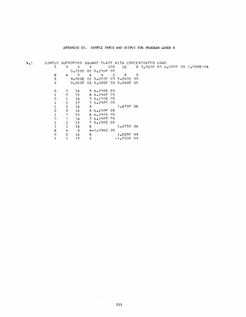
APPENDIX 13. SAMPLE INPUT AND OUTPUT FOR PROGRAM LAYER 8
9.1 SrMPLY SUPPORTFD SQUARE PLATF WrTH COPCENTRATFD LOAD 5 5 0 '3 100 16 8 '3.000F on 6.000F 00 1.000E-04
0.250E 00 0.250F 00 8 4 n 4 4 2 8 0 3 9.000E 02 5.oaOE 0'3 5.040E 05 3 9.000E 02 5.000E 03 5.040E 05
0 0 16 A 6.2,)OE 05 1 0 15 A A.?,)OF 05 0 1 16 7 1'l.2c,oE 05 1 1 1') 7 6.25nE 05 1 1 16 8 1.875E 06 0 0 16 8 6.250F 05 1 () Pi A ". ;''''i() F 05 0 1 16 7 6.2,)!'IE 05 1 1 15 7 6.250E 05 1 1 16 8 1.875E 06 8 4 8 4-1.000E 05 0 0 16 R I.DDOF 99 1 1 1 ') 7 -1.000F QQ
233
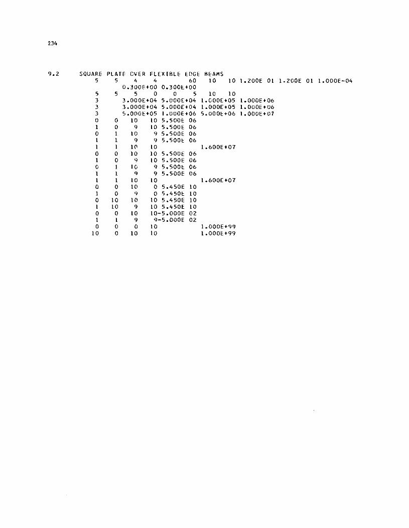
234
9.2 SQUARE PLATE eVER FLEXIBLE EDGE BEAMS 5 5 4 4 60 10 10 1.200E 01 1.200E 01 1.000E-04
0.300E+00 0.300[+00 5 5 5 0 0 5 10 10 3 3.000[+04 5.000[+04 I.GOO[+05 1.000E+06 3 3.000E+04 5.000[+04 1.000[+05 1.000[+06 3 5.000E+05 1.000E+06 5.000E+06 1.000E+07 0 0 10 10 5.500E 06 1 0 9 10 5.500E 06 0 1 10 9 5.500E 06 1 1 9 9 5.500E 06 1 1 10 10 1.600E+07 0 0 10 10 5.500E 06 1 0 9 10 5.500E 06 a 1 10 9 5.500E 06 1 1 q 9 5.500E 06 1 1 10 10 1.600E+07 0 0 10 0 5.450E 10 1 0 9 0 5.450E 10 0 10 10 10 5.450E 10 1 10 9 10 5.450E: 10 0 0 10 10-5.000E 02 1 1 9 9-5.000E 02 0 0 0 10 1.000E+99
10 0 10 10 1.000E+99
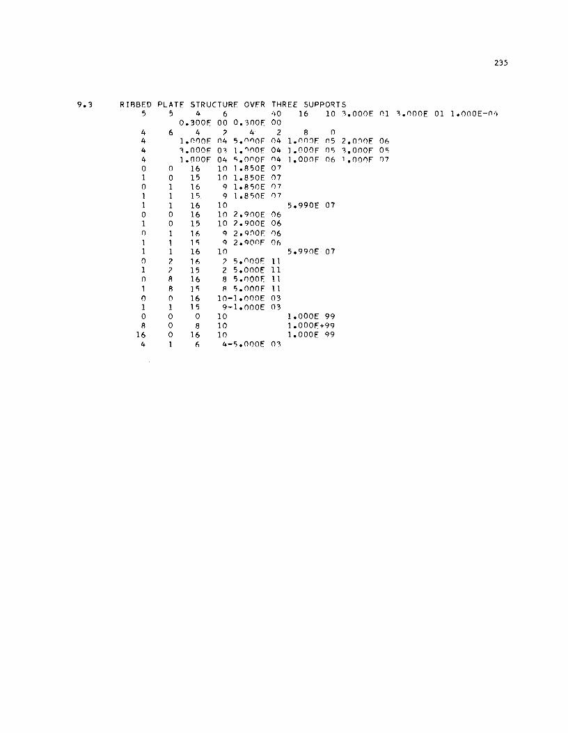
235
9.3 RIBBED PLATE STRUCTURE OVER THREE SUPPORTS 5 5 4 6 40 16 10 '.OOOE 01 '.OOOE 01 1.000E-(14
0.300E 00 O.,OOE 00 4 6 4 ? 4 2 8 0 4 1.0nOE 04 5.(1()OE 04 1.000E 05 2.0()OE 06 4 '.OOOE 0, 1.()()OE 04 J.OOOF 05 '.OOOF 00; 4 1.nOOE 04 'i.OOOF ()4 1.000F 06 '.oonF 07 0 0 16 10 1.850E 07 1 0 15 10 1.850E 07 0 1 16 9 1.8'iOE 07 1 1 15 9 1.8'iOE 07 1 1 16 10 5.990E 07 0 0 16 10 2.900E 06 1 0 15 10 2.900E 06 0 1 1(, 9 2.900f 06 1 1 1'i 9 2.900F 06 1 1 16 10 5.990E 07 0 2 16 ? 'i.OOOE 1 1 1 2 15 2 5.000E 11 0 8 16 8 'i.nOOE 1 1 1 8 1 'i R 'i.OOOE 1 1 0 () 16 10-1.000E 03 1 1 15 9-1.000E 03 0 0 0 10 1.000E 99 8 0 8 10 1.000E+99
16 0 16 10 1.000E 99 4 (, 4-'i.000E 0'3
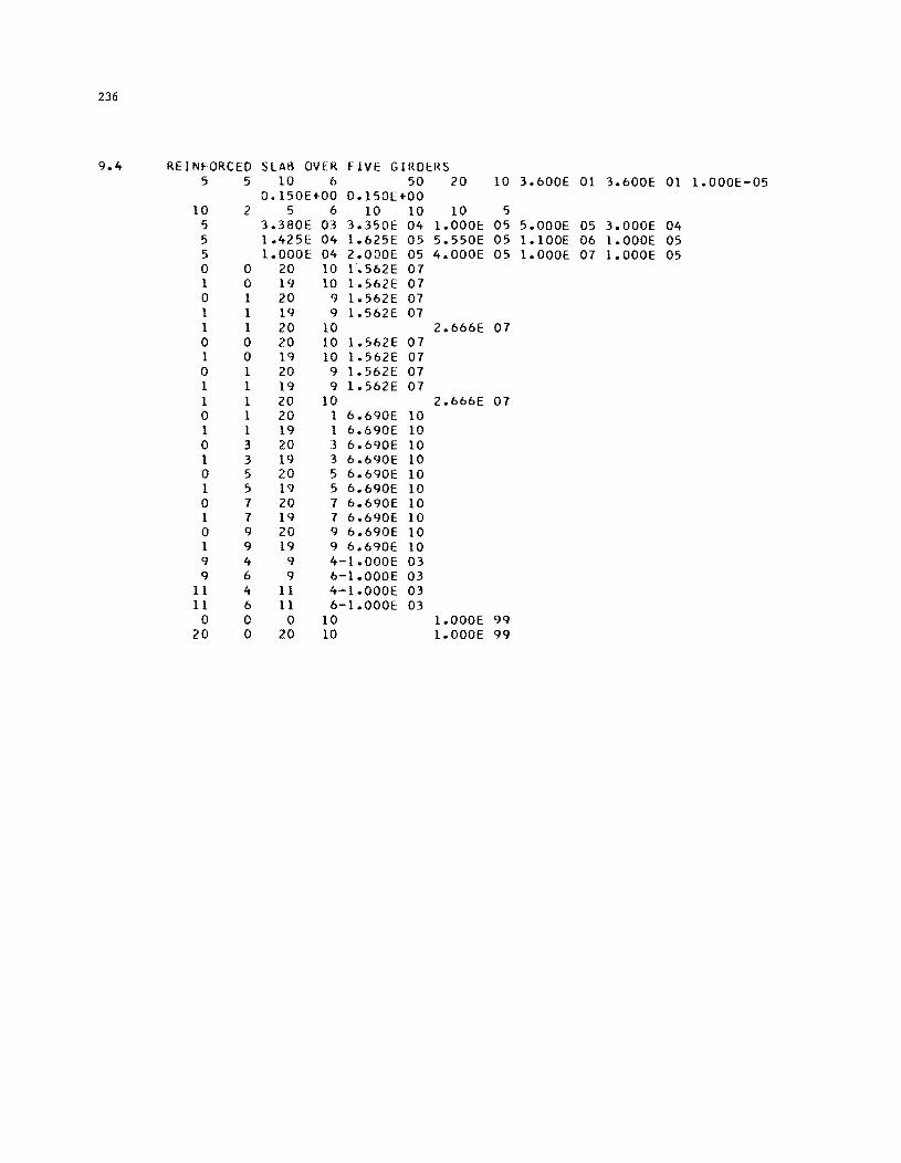
236
9.4 REINFORCED SLAB OVER FIVE GIRDERS 5 5 10 b 50 20 10 3.bOOE 01 3.bOOE 01 1.000E-05
0.150E+00 0.150E+00 10 2 5 b 10 10 10 5
5 3.380E 03 3.350E 04 1.000E 05 5.000E 05 3.000E 04 5 1.4251: 04 1.625E 05 5.550E 05 1. 100E 06 1.000E 05 5 1.000E 04 2.000E 05 4.000E 05 1.000E 07 1.000E 05 0 0 20 10 1.562E 07 1 0 19 10 1.562E 07 0 1 20 9 1.5b2E 07 1 I 19 9 1.5b2E 07 1 I 20 10 2.66bE 07 0 0 20 10 1.562E 07 1 0 19 10 1.562E 07 0 I 20 9 I.S62E 07 I I 19 9 1.562E 07 I 1 20 10 2.666E 07 0 1 20 1 6.690E 10 1 1 19 1 6.690E 10 0 3 20 3 6.690E 10 1 3 19 3 6.690E 10 0 5 20 5 6.690E 10 1 5 19 5 6.690E 10 0 7 20 7 6.690E 10 1 7 19 7 6.690E 10 0 9 20 9 6.690E 10 1 9 19 9 6.690E 10 9 4 9 4-1.000E 03 9 6 9 6-1.000E 03
11 4 11 4-1.000E 03 11 6 11 6-1.000E 03
0 0 0 10 1.000E 99 20 0 20 10 1.000E 99
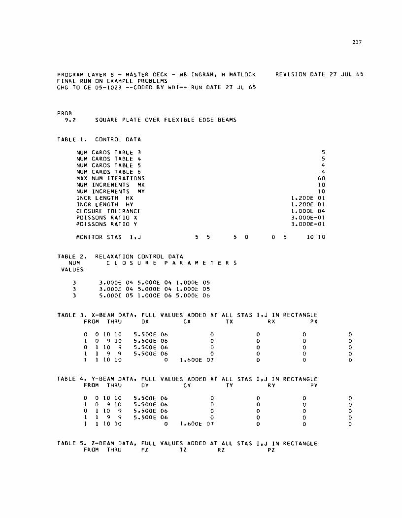
PROGRAM LAYER 8 - MASTER DECK - WB INGRAM, H MATLOCK FINAL RUN ON EXAMPLE PROBLEMS CHG TO CE 05-1023 --CODED BY WBI-- RUN DATE 27 JL 65
PROB 9.2 SQUARE PLATE OVER FLEXIBLE EDGE BEAMS
TABLE 1. CONTROL DATA
NUM CARDS TABLE 3 NUM CARDS TABLE 4 NUM CARDS TABLE 5 NUM CARDS TABLE 6 MAX NUM ITERATIONS NUM INCREMENTS MX NUM INCREMENTS MY INCR LENGTH HX INCR LENGTH HY CLOSURE TOLERANCE POISSONS RATIO X POISSONS RATIO Y
MON lTOR S TAS I,J 5 5 5 0
TABLE 2. RELAXATION CONTROL DATA NUM C LOS U R E PAR A MET E R S
VALUES
3 3.000E 04 5.000E 04 1.000E 05 3 3.000E 04 5.000E 04 1.000f: 05 3 5.000E 05 1.000E 06 5.0001:. 06
TABLE 3. X-BEAM DATA, FULL VALUES ADDED AT ALL STAS FROM THRU OX CX TX
0 0 10 10 5.500E 06 0 1 0 9 10 5.500E 06 0 0 1 10 9 5.500E 06 0 1 1 9 9 5.500E 06 0 1 1 10 10 0 1.600E 07
TABLE 4. Y-BEAM DATA, FULL VALUES ADDED AT ALL STAS FROM THRU DY CY TY
0 0 10 10 5.500E 06 0 1 0 9 10 5.500E 06 0 0 1 10 9 5.500E 06 0 1 1 9 9 5.500E 06 0 I 1 10 10 0 1.600E 07
TABLE 5. Z-BEAM DATA, FULL VALUES ADDED AT ALL STAS FROM THRU FZ TZ RZ
237
REVISION DATE 27 JUL 65
5 5 4 4
60 10 10
1.200E 01 1.200E 01 1.000E-04 3.000E-Ol 3.000E-Ol
0 5 10 10
I,J IN RECTANGLE RX PX
0 0 0 0 0 0 0 0 0 0 0 0 0 0 0
I,J IN RECTANGLE RY PY
0 0 0 0 0 0 0 0 0 0 0 0 0 0 0
I, J IN RECTANGLE PZ
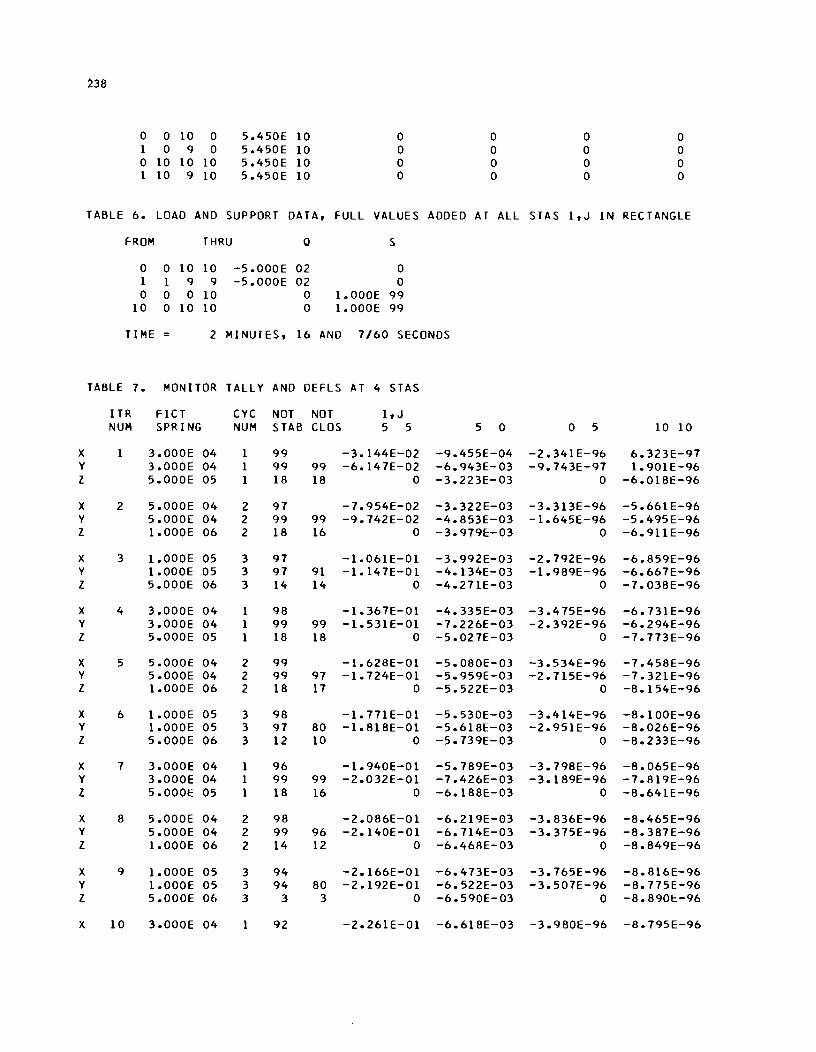
238
0 0 10 0 5.450E 10 0 0 0 0 1 0 9 0 5.450E 10 0 0 0 0 0 10 10 10 5.450E 10 0 0 0 0 1 10 9 10 5.450E 10 0 0 0 0
TABLE 6. LOAD AND SUPPORT DATA, FULL VALUES ADDED AT ALL STAS I, J IN RECTANGLE
FROM THRU 0 S
0 0 10 10 -5.000E 02 0 1 1 9 9 -5.000E 02 0 0 0 0 10 0 1.000E 99
10 0 10 10 0 1.000E 99
TIME 2 MINUTES, 16 AND 7/60 SECONDS
TABLE 7. MONITOR TALLY AND DEFLS AT 4 STAS
ITR FICT CYC NOT NOT I, J NUM SPRING NUM STAB CLOS 5 5 5 0 0 5 10 10
X 1 3.000E 04 1 99 -3.144E-02 -9.455E-04 -2.341E-96 6.323E-97 Y 3.000E 04 1 99 99 -6.147E-02 -6.943E-03 -9.743E-97 1.901E-96 l 5.000E 05 1 18 18 0 -3.223E-03 0 -6.018E-96
X 2 5.000E 04 2 97 -7.954E-02 -3.322E-03 -3.313E-96 -5.661E-96 Y 5.000E 04 2 99 99 -9.742E-02 -4.853E-03 -1.645E-96 -5.495E-96 l 1.000E 06 2 18 16 0 -3.979E-03 0 -6.911E-96
X 3 1.000E 05 3 97 -1.061E-01 -3.992E-03 -2.792E-96 -6.859E-96 Y 1.000E 05 3 97 91 -1.147E-01 -4.134E-03 -1.989E-96 -6.667E-96 l 5.000E 06 3 14 14 0 -4.271E-03 0 -7.038E-96
X 4 3.000E 04 1 98 -1.367E-01 -4.335E-03 -3.475E-96 -6.73IE-96 Y 3.000E 04 1 99 99 -1.531 E-01 -7.226E-03 -2.392E-96 -6.294E-96 l 5.000E 05 1 18 18 0 -5.027E-03 0 -7.773E-96
X 5 5.000E 04 2 99 -1.628E-Ol -5.080E-03 -3.534E-96 -7.458E-96 Y 5.000E 04 2 99 97 -1.724E-01 -5.959E-03 -2.715E-96 -7.321E-96 l 1.000E 06 2 18 17 0 -5.522E-03 0 -8.154E-96
X 6 1.000E 05 3 98 -1.771E-01 -5.530E-03 -3.414E-96 -8.100E-96 Y 1.000E 05 3 97 80 -1.818E-01 -5.618E-03 -2.951E-96 -8.026E-96 l 5.000E 06 3 12 10 0 -5.739E-03 0 -8.233E-96
X 7 3.000E 04 1 96 -1.940E-01 -5.789E-03 -3.798E-96 -8.065E-96 Y 3.000E 04 1 99 99 -2.032E-01 -7.426E-03 -3.189E-96 -7.819E-96 l 5.000E 05 1 18 16 0 -6.188E-03 0 -8.64IE-96
X 8 5.000E 04 2 98 -2.086E-01 -6.219E-03 -3.836E-96 -8.465E-96 Y 5.000E 04 2 99 96 -2.140E-01 -6.714E-03 -3.375E-96 -8.387E-96 l 1.000E 06 2 14 12 0 -6.468E-03 0 -8.849E-96
X 9 1.000E 05 3 94 -2.166E-01 -6.473E-03 -3.765E-96 -8.816E-96 Y 1.000E 05 3 94 80 -2.192E-01 -6.522E-03 -3.507E-96 -8.775E-96 l 5.000E 06 3 3 3 0 -6.590E-03 0 -8.890E-96
X 10 3.000E 04 92 -2.26IE-01 -6.618E-03 -3.980E-96 -8.795E-96
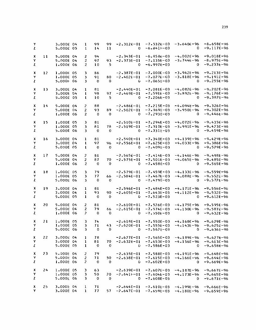
239
y 3.000E 04 1 99 99 -2.312£-01 -7.532E-03 -3.640£-96 -8.658E-96 I 5.000E 05 1 14 11 0 -6.841E-03 0 -9.117£-96
X 11 5.000£ 04 2 94 -2.343E-Ol -6.858£-03 -4.002E-96 -9.018E-96 Y 5.000E 04 2 97 93 -2.373E-Ol -7.135£-03 -3.744£-96 -8.975E-96 I 1.000E 06 2 10 5 0 -6.997E-03 0 -9.233E-96
X 12 1.000E 05 3 86 -2.387E-Ol -7.000E-03 -3.962E-96 -9.213E-96 Y 1.000E 05 3 91 80 -2.402E-Ol -7.027E-03 -3.818E-96 -9.191[-96 I 5.0001:: 06 3 0 0 (j -7.065E-03 0 -9.2551::-96
X 13 3.000E 04 1 81 -2.440E-Ol -7.081E-03 -4.082E-96 -9.202E-96 Y 3.000E 04 1 98 97 -2.469E-Ol -7.591E-03 -3.892E-96 -9.126E-96 I 5.000E 05 1 10 5 0 -7.206E-03 0 -9.382E-96
X 14 5.000E 04 2 88 -2.486[-01 -7.215E-03 -4.0941::-96 -9.326E-96 Y 5.000E 04 2 93 89 -2.502E-Ol -7.369E-03 -3.950E-96 -9.302E-96 I 1.000E 06 2 0 0 0 -7.293E-03 0 -9.446E-96
X 15 1.000E 05 3 81 -2.510E-Ol -7.294E-03 -4.072E-96 -9.435E-96 Y 1.000E 05 3 81 78 -2.519E-Ol -7.310E-03 -3.991E-96 -9.423E-96 I 5.000E 06 3 0 0 0 -7.331E-03 0 -9.459E-96
X 16 3.000E 04 1 81 -2.540E-Ol -7.340E-03 -4.139E-96 -9.429E-96 Y 3.000E 04 1 97 96 -2.556E-Ol -7.625E-03 -4.033E-96 -9.386E-96 I 5.000E 05 1 0 0 0 -7.409E-03 0 -9.529E-96
X 1 7 5.000E 04 2 81 -2.565E-Ol -7.414E-03 -4.146E-96 -9.498E-96 Y 5.000E 04 2 87 70 -2.575E-Ol -7.501E-03 -4.065E-96 -9.485E-96 I 1.000E 06 2 0 0 0 -7.458£-03 0 -9.565E-96
X 18 1.000E 05 3 79 -2.579E-Ol -7.459E-03 -4.133E-96 -9.559E-96 Y 1.000E 05 3 77 66 -2.584E-Ol -7.467E-03 -4.088E-96 -9.552[-96 I 5.000E 06 3 0 0 0 -7.479E-03 0 -9.572E-96
X 19 3.000E 04 1 81 -2.596E-Ol -7.484E-03 -4.1 71E -96 -9.556E-96 Y 3.000E 04 1 93 90 -2.605E-Ol -7.643E-03 -4.112E-96 -9.532E-96 I 5.0001:: 05 1 0 0 (j -7.523E-03 0 -9.612E-96
X 20 5.000E 04 2 81 -2.610E-Ol -7.526E-03 -4.175E-96 -9.595E-96 Y 5.0001:: 04 2 79 66 -2.615E-Ol -7.574E-03 -4.130E-96 -9.587£-96 I 1.000E 06 2 0 0 0 -7.550E-03 0 -9.632E-96
X 21 1.000E 05 3 74 -2.618E-Ol -7.550E-03 -4.168E-96 -9.629E-96 Y 1.000E 05 3 71 43 -2.620E-Ol -7.555E-03 -4.143E-96 -9.625[-96 I 5.000E 06 3 0 0 0 -7.562E-03 0 -9.636E-96
X 22 3.000E 04 1 78 -2.627E-Ol -7.565E-03 -4.189E-96 -9.627E-96 Y 3.000E 04 1 81 70 -2.632E-Ol -7.653E-03 -4.156E-96 -9.613E-96 I 5.000E 05 1 0 0 0 -7.586E-03 0 -9.658E-96
X 23 5.000E 04 2 79 -2.635E-Ol -7.588E-03 -4.191E-96 -9.648E-96 Y 5.000E 04 2 71 50 -2.638E-Ol -7.615E-03 -4.166E-96 -9.644E-96 I 1.000E 06 2 0 0 0 -7.602E-03 0 -9.669E-96
X 24 1.000E 05 3 63 -2.639E-Ol -7.602E-03 -4.187E-96 -9.667E-96 Y 1.000E 05 3 50 20 -2.64lE-01 -7.604E:-03 -4.173E-96 -9.665E-96 I 5.000E 06 3 0 0 0 -7.608E-03 0 -9.671E-96
X 25 3.0001:: 04 1 71 -2.644E-Ol -7.610E-03 -4.199E-96 -9.666E-96 Y 3.000E 04 1 77 57 -2.647E-Ol -7.659E-03 -4.180E-96 -9.659E-96

240
I 5.000E OS 0 0 0 -7.622E-03 0 -9.684E-96
X 26 S.OOOE 04 2 71 -2.649E-Ol -7.623£-03 -4.200E-96 -9.678E-96 Y 5.000E 04 2 52 28 -2.650E-Ol -7.638E-03 -4.186E-96 -9.676E-96 I 1.000E 06 2 0 0 0 -7.630E-03 0 -9.690E-96
X 27 1.000E 05 3 44 -2.651E-Ol -7.6301::-03 -4.198E-96 -9.689E-96 Y 1.000£ 05 3 25 0 -2.652E-01 -7.632E-03 -4.190E-96 -9.688E-96 I 5.000E 06 3 0 0 0 -7.634E-03 0 -9.6<HE-96
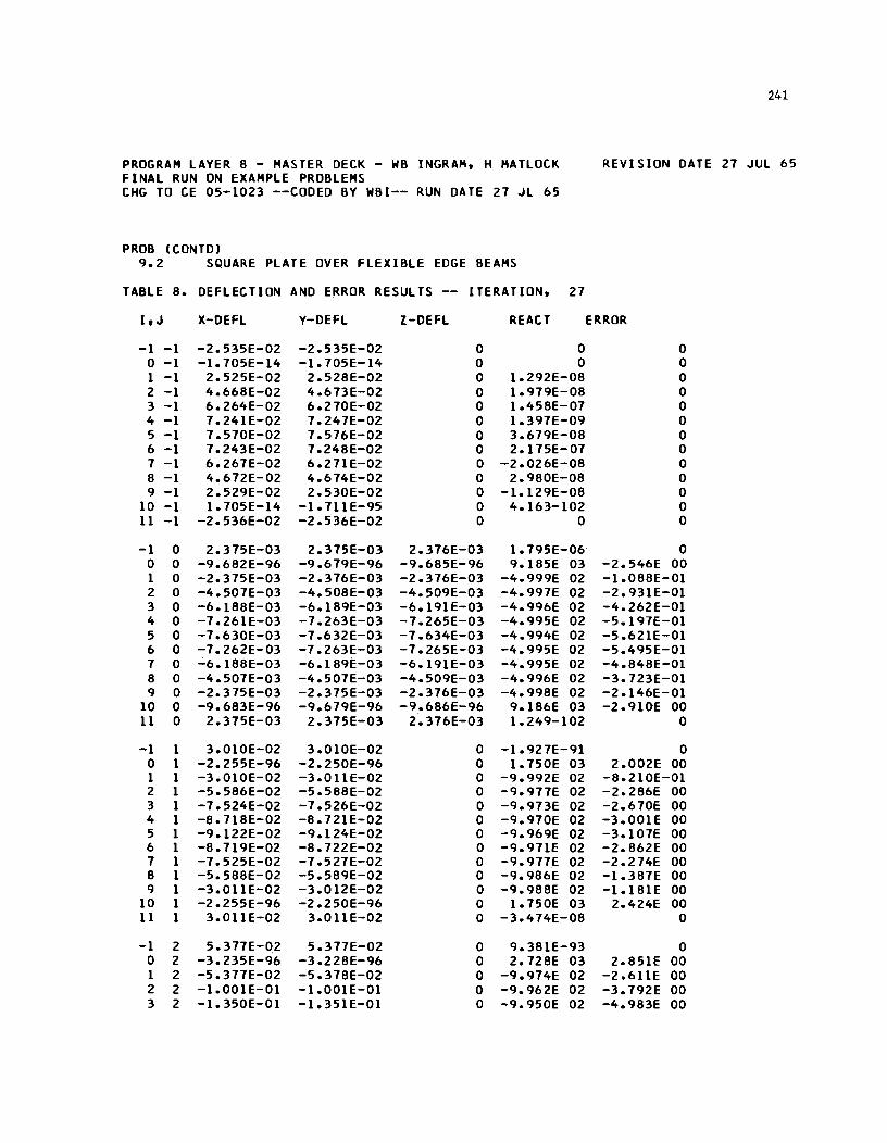
PROGRAM LAYER 8 - MASTER DECK - WB INGRAM. H MATLOCK FINAL RUN ON EXAMPLE PROBLEMS CHG TO CE 05-1023 --CODED BY WBI-- RUN DATE 27 JL 65
PROB (CONTO) 9.2 SQUARE PLATE OVER FLEXIBLE EDGE BEAMS
TABLE 8. DEFLECTION AND ERROR RESULTS -- ITERATION. 27
I, J X-DEFL Y-DEFL l-DEFL REACT
-1 -1 -2.535E-02 -2.535E-02 0 0 0 -1 -1.705E-14 -1.705E-14 0 0 1 -1 2.525E-02 2.528E-02 0 1.292E-08 2 -1 4.668E-02 4.673E-02 0 1.979E-08 3 -1 6.264E-02 6.270E-02 0 1.458E-07 4 -1 7.241E-02 7.247E-02 0 1.397E-09 5 -1 7.570E-02 7.576E-02 0 3.679E-08 6 -1 7.243E-02 7.248E-02 0 2.175E-07 7 -1 6.267E-02 6.271E-02 0 -2.026E-08 8 -1 4.672E-02 4.674E-02 0 2.980E-08 9 -1 2.529E-02 2.530E-02 0 -1.129E-08
10 -1 1.705E-14 -1.7llE-95 0 4.163-102 II -1 -2.536E-02 -2.536E-02 0 0
-1 0 2.375E-03 2.375E-03 2.376E-03 1.795E-06 0 0 -9.682E-96 -9.679E-96 -9.685E-96 9.185E 03 1 0 -2.375E-03 -2.376E-03 -2.376E-03 -4.999E 02 2 0 -4.507E-03 -4.508E-03 -4.509E-03 -4.997E 02 3 0 -6.188E-03 -6.189E-03 -6.191E-03 -4.996E 02 4 0 -7.26lE-03 -7.263E-03 -7.265E-03 -4.995E 02 5 0 -7.630E-03 -7.632E-03 -7.634E-03 -4.994E 02 6 0 -7.262E-03 -7.263E-03 -7.265E-03 -4.995E 02 7 0 -6.188E-03 -6.189E-03 -6.19lE-03 -4.995E 02 8 0 -4.507E-03 -4.507E-03 -4.509E-03 -4.996E 02 9 0 -2.375E-03 -2.375E-03 -2.376E-03 -4.998E 02
10 0 -9.683E-96 -9.679E-96 -9.686E-96 9.186E 03 II 0 2.375E-03 2.375E-03 2.376E-03 1.249-102
,..1 1 3.010E-02 3.010E-02 0 -1.927E-91 0 1 -2.255E-96 -2.250E-96 0 1.750E 03 1 1 -3.010E-02 -3.0llE-02 0 -9.992E 02 2 1 -5.586E-02 -5.588E-02 0 -9.977E 02 3 1 -7.524E-02 -7.526E-02 0 -9.973E 02 4 1 -8.718E-02 -8.72lE-02 0 -9.970E 02 5 1 -9.122E-02 -9.124E-02 0 -9.969E 02 6 1 -8.719E-OZ -8.722E-02 0 -9.971E 02 7 1 -7.525E-02 -7.527E-02 0 -9.977E 02 8 1 -5.588E-02 -5.589E-02 0 -9.986E 02 9 1 -3.0llE-02 -3.012E-02 0 -9.988E 02
10 1 -2.255E-96 -2.250E-96 0 1.750E 03 II 1 3.0llE-02 3.011E-02 0 -3.474E-08
-1 2 5.377E-02 5.377E-02 0 9.381E-93 0 2 -3.235E-96 -3.228E-96 0 2.728E 03 1 2 -5.377E-02 -5.378E-02 0 -9.974E 02 2 2 -1.00lE-01 -1.001E-01 0 -9.962E 02 3 2 -1.350E-01 -1.351E-01 0 -..9. 950E 02
241
REVISION DATE 27 JUL 65
ERROR
0 0 0 0 0 0 0 0 0 0 0 0 0
0 -2.546E 00 -1.088E-01 -2.931E-01 -4.262E-01 -5.197E-01 -5.621E-01 -5.495E-01 -4.848E-01 -3.723E-01 -2.146E-01 -2.910E 00
0
0 2.002E 00
-8.210E-01 -2.286E 00 -2.670E 00 -3.00lE 00 -3.107E 00 -2.862E 00 -2.274E 00 -1.387E 00 -1.18lE 00
2.424E 00 0
0 2.851E 00
-2.6llE 00 -3.792E 00 -4.983E 00
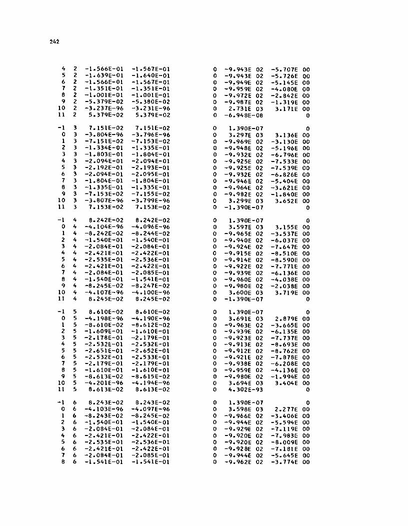
24~
4 2 -1.566E-Ol -1.567E-01 0 -9.943E 02 -5.707E 00 5 2 -1.639E-01 -1.640E-Ol 0 -9.943E 02 -5.726E 00 6 2 -1.566E-Ol -1.567E-Ol 0 -9~949E 02 -5.145E 00 7 2 -1.351E-Ol -1.351E-Ol 0 -9.959E 02 -4.080E 00 8 2 -1.001E-Ol -1.001E-Ol 0 -9.972E 02 -2.842E 00 9 2 -5.379E-02 -5.380E-02 0 -9.987E 02 -1.319E 00
10 2 -3.237E-96 -3.231E-96 0 2.731E 03 3.171E 00 11 2 5.379E-02 5.379E-02 0 -6.948E-08 0
-1 3 7.151E-02 7.151E-02 0 1.390E-07 0 0 3 -3.804E-96 -3.796E-96 0 3.297E 03 3.136E 00 1 3 -7.151E-02 -7.153E-02 0 -9.969E 02 -3.130E 00 2 3 -1.334E-Ol -1.335E-Ol 0 -9.948E 02 -5.196E 00 3 3 -1.803E-01 -1.804E-Ol 0 -9.932E 02 -6.796E 00 4 3 -2.094E-Ol -2.094E-Ol 0 -9.925E 02 -7.533E 00 5 3 -2.192E-Ol -2.193E-Ol 0 -9.925E 02 -7.539E 00 6 3 -2.094E-Ol -2.095E-Ol 0 -9.932E 02 -6.826E 00 7 3 -1.804E-Ol -1.804E-Ol 0 -9.946E 02 -5.404E 00 8 3 -1.335E-Ol -1.335E-Ol 0 -9.964E 02 -3.621E 00 9 3 -7.153E-02 -7.155E-02 0 -9.982E 02 -1.840E 00
10 3 -3.807E-96 -3.799E-:96 0 3.299E 03 3.652E 00 11 3 7.153E-02 7.153E-02 0 -1.390E-07 0
-1 4 8.242E-02 8.242E-02 0 1.390E-07 0 0 4 -4.104E-96 -4.096E-96 0 3.597E 03 3.155E 00 1 4 -8.242E-02 -8.244E-02 0 -9.965E 02 -3.537E 00 2 4 -1.540E-Ol -1.540E-Ol 0 -9.940E 02 -6.037E 00 3 4 -2.084E-Ol -2.084E-Ol 0 -9.924E 02 -7.647E 00 4 4 -2.421E-Ol -2.422E-01 0 -9.915E 02 -8.510E 00 5 4 -2.535E-Ol -2.536E-01 0 -9.914E 02 -8.590E 00 6 4 -2.421E-01 -2.422E-Ol 0 -9.922E 02 -7.771E 00 7 4 -2.084E-Ol -2.085E-Ol 0 -9.939E 02 -6.136E 00 8 4 -1.540E-Ol -1.541E-Ol 0 -9.960E 02 -4.038E 00 9 4 -8.245E-02 -8.247E-02 0 -9.980E 02 -2.038E 00
10 4 -4.107E-96 -4.100E-96 0 3.600E 03 3.719E 00 11 4 8.245E-02 8.245E-02 0 -1.390E-07 0
-1 5 8.610E-02 8.610E-02 0 1.390E-07 0 0 5 -4.198E-96 -4.190E-96 0 3.691E 03 2.879E 00 1 5 -8.610E-02 -8.612E-02 0 -9.963E 02 -3.665E 00 2 5 -1.609E-Ol -1.610E-Ol 0 -9.939E 02 -6.135E 00 3 5 -2. 178E-Ol -2.179E-Ol 0 -9.923E 02 -7.737E 00 4 5 -2.532E-Ol -2.532E-Ol 0 -9.913E 02 -8.693E 00 5 5 -2.651E-Ol -2.652E-Ol 0 -9.912E 02 -8.762E 00 6 5 -2.532E-Ol -2.533E-Ol 0 -9.921E 02 -7.878E 00 7 5 -2.179E-Ol -2.179E-Ol 0 -9.938E 02 -6.208E 00 8 5 -1.610E-Ol -1.610E-Ol 0 -9.959E 02 -4.136E 00 9 5 -8.613E-02 -8.615E-02 0 -9.980E 02 -1.994E 00
10 5 -4.201E-96 -4.194E-96 0 3.694E 03 3.404E 00 11 5 8.613E-02 8.613E-02 0 4.302E-93 0
-1 6 8.243E-02 8.243E-02 0 1.390E-07 0 0 6 -4.103E-96 -4.097E-96 0 3.598E 03 2.277E 00 1 6 -8.243E-02 -8.245E-02 0 -9.966E 02 -3.406E 00 2 6 -1.540E-Ol -1.540E-Ol 0 -9.944E 02 -5.594E 00 3 6 -2.084E-Ol -2.084E-Ol 0 -9.92ge 02 -7.119E 00 4 6 -2.421E-Ol -2.422E-Ol 0 -9.920E 02 -7.983E 00 5 6 -2.535E-Ol -2.536E-Ol 0 -9.920E 02 -8.009E 00 6 6 -2.421E-Ol -2.422E-Ol 0 -9.928E 02 -7.181E 00 7 6 -2.084E-Ol -2.085E-Ol 0 -9.944e 02 -5.645E 00 8 6 -1.541E-Ol -1.541E-01 0 -9.962E 02 -3.774E 00
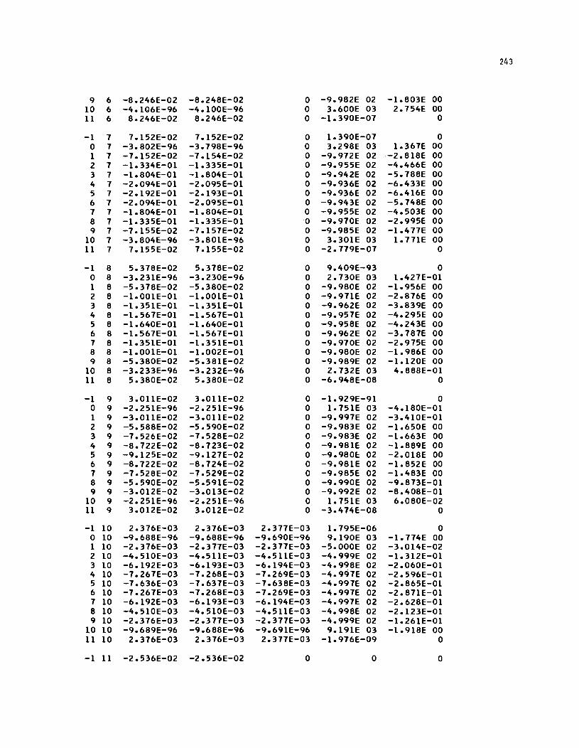
243
9 6 -8.246E-02 -8.248E-02 0 -9.982E 02 -1.803E 00 10 6 -4.106E-96 -4.100E-96 0 3.600E 03 2.754E 00 11 6 8.246E-02 8.246E-02 0 -1.390E-07 0
-1 7 7.152E-02 7.152E-02 0 1.390E-07 0 0 7 -3.802E-96 -3.798E-96 0 3.298E 03 1.367E 00 1 7 -7.152E-02 -7.154E-02 0 -9.972E 02 -2.818E 00 2 7 -1.334E-Ol -1.335E-Ol 0 -9.955E 02 -4.466E 00 3 7 -1.804E-Ol -1.804E-Ol 0 -9.942E 02 -5.788E 00 4 7 -2.094E-Ol -2.095E-Ol 0 -9.936E 02 -6.433E 00 5 7 -2.192E-Ol -2.193E-Ol 0 -9.936E 02 -6.416E 00 6 7 -2.094E-Ol -2.095E-Ol 0 -9.943E 02 -5.748E 00 7 7 -1.804E-Ol -1.804E-Ol 0 -9.955E 02 -4.503E 00 8 7 -1.335E-Ol -1.335E;"01 0 -9.970E 02 -2.995E 00 9 7 -7.155E-02 -7.157E-02 0 -9.985E 02 -1.477E 00
10 7 -3.804E-96 -3.80lE-96 0 3.30lE 03 1.771E 00 11 7 7.155E-02 7.155E-02 0 -2.779E-07 0
-1 8 5.378E-02 5.378E-02 0 9.409E-93 0 0 8 -3.231E-96 -3.230E-96 0 2.730E 03 1.427E-Ol 1 8 -5.378E-02 -5.380E-02 0 -9.980E 02 -1.956E 00 2 8 -1.00lE-01 -1.00lE-01 0 -9.971E 02 -2.876E 00 3 8 -1.35lE-01 -1.35lE-01 0 -9.962E 02 -3.839E 00 4 8 -1.567E-Ol -1.567E-Ol 0 -9.957E 02 -4.295E 00 5 8 -1.640E-Ol -1.640E-Ol 0 -9.958E 02 -4.243E 00 6 8 -1.567E-Ol -1.567E-Ol 0 -9.962E 02 -3.787E 00 7 8 -1.35lE-01 -1.35lE-01 0 -9.970E 02 -2.975E 00 8 8 -1.00IE-Ol -1.002E-Ol 0 -9.980E 02 -1.986E 00 9 8 -5.380E-02 -5.38lE-02 0 -9.989E 02 -1.120E 00
10 8 -3.233E-96 -3.232E-96 0 2.732E 03 4.888E-Ol 11 8 5.380E-02 5.380E-02 0 -6.948E-08 0
-1 9 3.011E-02 3.011E-02 0 -1.929E-91 0 0 9 -2.25lE-96 -2.251E-96 0 1.751E 03 -4.180E-Ol 1 9 -3.011E-02 -3.011E-02 0 -9.997E 02 -3.410E-Ol 2 9 -5.588E-02 -5.590E-02 0 -9.983E 02 -1.650E 00 3 9 -7.526E-02 -7.528E-02 0 -9.983E 02 -1.663E 00 4 9 -8.722E-02 -8.723E-02 0 -9.981E 02 -1.889E 00 5 9 -9.125E-02 -9.127E-02 0 -9.980E 02 -2.018E 00 6 9 -8.722E-02 -8.724E-02 0 -9.98lE 02 -1.852E 00 7 9 -7.528E-02 -7.529E-02 0 -9.985E 02 -1.483E 00 8 9 -5.590E-02 -5.59lE-02 0 -9.990E 02 -9.873E-Ol 9 9 -3.012E-02 -3.013E-02 0 -9.992E 02 -8.408E-Ol
10 9 -2.25lE-96 -2.25lE-96 0 1.75lE 03 6.080E-02 11 9 3.012E-02 3.012E-02 0 -3.474E-08 0
-1 10 2.376E-03 2.376E-03 2.377E-03 1.795E-06 0 0 10 -9.688E-96 -9.688E-96 -9.690E-96 9.190E 03 -1.774E 00 1 10 -2.376E-03 -2.377E-03 -2.377E-03 -5.000E 02 -3.014E-02 2 10 -4.510E-03 -4.511E-03 -4.511E-03 -4.999E 02 -1.312E-Ol 3 10 -6.192E-03 -6.193E-03 -6.194E-03 -4.998E 02 -2.060E-Ol 4 10 -7.267E-03 -7.268E-03 -7.269E-03 -4.997E 02 -2.596E-Ol 5 10 -7.636E-03 -7.637E-03 -7.638E-03 -4.997E 02 -2.865E-Ol 6 10 -7.267E-03 -7.268E-03 -7.269E-03 -4.997E 02 -2.871E-Ol 7 10 -6.192E-03 -6.193E-03 -6. 194E-03 -4.997E 02 -2.628E-Ol 8 10 -4.510E-03 -4.510E-03 -4.511E-03 -4.998E 02 -2.123E-Ol 9 10 -2.376E-:-03 -2.377E-03 -2.377E-03 -4.999E 02 -1.261E-Ol
10 10 -9.689E-96 -9.688E-96 -9.691E-96 9.191E 03 -1.918E 00 11 10 2.376E-03 2.376E-03 2.377E-03 -1.976E-09 0
-1 11 -2.536E-02 -2.536E-02 0 0 0
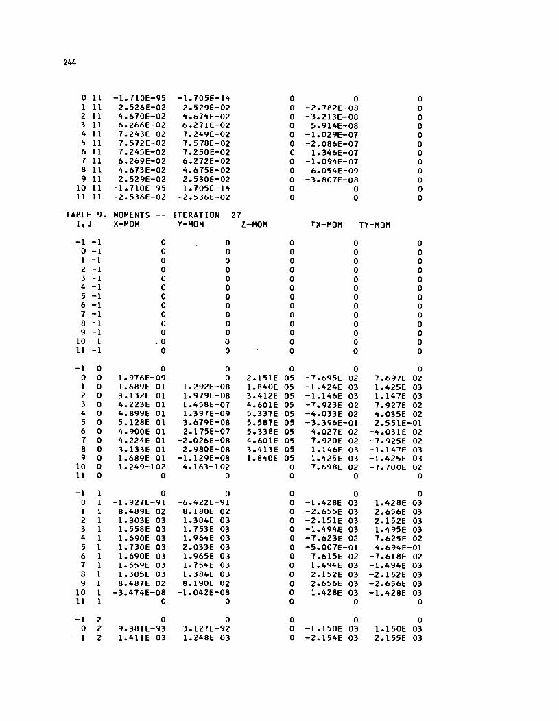
~44
0 11 -1.1l0E-95 -1.105E-14 0 0 0 1 11 2.526E-02 2.529E-02 0 -2.1S2E-OS 0 2 11 4.610E-02 4.614E-02 0 -3 .• 213E-OS 0 3 11 6.266E-02 6.21lE-02 0 5.914E-OS 0 4 11 1.243E-02 1.249E-02 0 -1.029E-01 0 5 11 1.512E-02 1.51SE-02 0 -2.0S6E-01 0 6 11 1.245E-02 1.250E-02 0 1.346E-01 0 1 11 6.269E-02 6.212E-02 0 -1.094E-01 0 S 11 4.613E-02 4.615E-02 0 6.054E-09 0 9 11 2.529E-02 2.530E-02 0 -3.S01E-OS 0
10 11 -1.1l0E-95 1.105E-14 0 0 0 11 11 -2.536E-02 -2.536E-02 0 0 0
TABLE 9. MOMENTS ITERATION 21 I, J X-MOM V-MOM Z-MOM TX-MOM TV-MOM
-1 -1 0 0 0 0 0 0 -1 0 0 0 0 0 1 -1 0 0 0 0 0 2 -1 0 0 0 0 0 3 -1 0 0 0 0 0 4 -1 0 0 0 0 0 5 -1 0 0 0 0 0 6 -1 0 0 0 0 0 1 -1 0 0 0 0 0 S -1 0 0 0 0 0 9 -1 0 0 0 0 0
10 -1 • 0 0 0 0 0 11 -1 0 0 0 0 0
-1 0 0 0 0 0 0 0 0 1.916E-09 0 2.151E-05 -1.695E 02 1.691E 02 1 0 1.6S9E 01 1.292E-OS 1.S40E 05 -1.424E 03 1.425E 03 2 0 3.132E 01 1.919E-OS 3.412E 05 -1.146E 03 1.141E 03 3 0 4.223E 01 1.45SE-01 4.60lE 05 -1.923E 02 1.921E 02 4 0 4.S99E 01 1.391E-09 5.331E 05 -4.033E 02 4.035E 02 5 0 5.12SE 01 3.619E-OS 5.5S1E 05 -3.396E-01 2.551E-01 6 0 4.900E 01 2.115E-01 5.33SE 05 4.021E 02 -4.031E 02 1 0 4.224E 01 -2.026E-OS 4.601E 05 1.920E 02 -1.925E 02 S 0 3.133E 01 2.9S0E-OS 3.413E 05 1.146E 03 -1.147E 03 9 0 1.6S9E 01 -1.129E-OS 1.S40E 05 1.425E 03 -1.425E 03
10 0 1.249-102 4.163-102 0 1.69SE 02 -7.100E 02 11 0 0 0 0 0 0
-1 1 0 0 0 0 0 0 1 -1.921E-91 -6.422E-91 0 -1.42SE 03 1.42SE 03 1 1 S.4S9E 02 S.lS0E 02 0 -2.655E 03 2.656E 03 2 1 1.303E 03 1.3S4E 03 0 -2.151E 03 2.152E 03 3 1 1.55SE 03 1.153E 03 0 -1.494E 03 1.495E 03 4 1 1.690E 03 1.964E 03 0 -1.623E 02 1.625E 02 5 1 1.130E 03 2.033E 03 0 -5.001E-01 4.694E-01 6 1 1.690E 03 1.965E 03 0 7.615E 02 -1.61SE 02 1 1 1.559E 03 1.154E 03 0 1.494E 03 -1.494E 03 S 1 1.30SE 03 1.3S4E 03 0 2.152E 03 -2.152E 03 9 1 S.4S1E 02 S.190E 02 0 2.656E 03 -2.6561: 03
10 1 -3.414E-OS -1.042E-OS 0 1.42SE 03 -1.42SE 03 11 1 0 0 0 0 0
-1 2 0 0 0 0 0 0 2 9.3SlE-93 3.127E-92 0 -1.150E 03 1.150E 03 1 2 1.411E 03 1.24SE 03 0 -2.154E 03 2.155E 03

245
2 2 2.235E 03 2.184E 03 0 -1.769E 03 1.770E 03 3 2 2.706E 03 2.829E 03 0 -1.240E 03 1.240E 03 4 2 2.949E 03 3.206E 03 0 -6.359E 02 6.360E 02 5 2 3.025E 03 3.330E 03 0 -4.743E-OI 4.039E-OI 6 2 2.950E 03 3.206E 03 0 6.351E 02 -6.354E 02 7 2 2.708E 03 2.830E 03 0 1.240E 03 -1.240E 03 8 2 2.237E 03 2.185E 03 0 1.769E 03 -1.770E 03 9 2 1.412E 03 1.248E 03 0 2.155E 03 -2.156E 03
10 2 -6.948E-08 -2.084E-08 0 1.151E 03 -1.15IE 03 11 2 0 0 0 0 0
-1 3 0 0 0 0 0 0 3 1.390E-07 4.169E-08 0 -7.958E 02 7.959E 02 1 3 1.780E 03 1.483E 03 0 -1.497E 03 1.498E 03 2 3 2.876E 03 2.638E 03 0 -1.241E 03 1.241E 03 3 3 3.520E 03 3.457E 03 0 -8.767E 02 8.769E 02 4 3 3.856E 03 3.944E 03 0 -4.5l7E 02 4.518E 02 5 3 3.960E 03 4.106E 03 0 -3.159E-Ol 3.028E-Ol 6 3 3.857E 03 3.945E 03 0 4.511E 02 -4.513E 02 7 3 3.523E 03 3.458E 03 0 8.764E 02 -8.767E 02 8 3 2.879E 03 2.640E 03 0 1.241E 03 -1.242E 03 9 3 1.781E 03 1.484E 03 0 1.498E 03 -1.498E 03
10 3 -1.390E-07 -4.169E-08 0 7.962E 02 -7.963E 02 11 3 0 0 0 0 0
-1 4 0 0 0 0 0 0 4 1.390E-07 4.169E-08 0 -4.052E 02 4.053E 02 1 4 1.989E 03 1.603E 03 0 -7.643E 02 7.645E 02 2 4 3.25lE 03 2.870E 03 0 -6.367E 02 6.368E 02 3 4 4.005E 03 3.782E 03 0 -4.51aE 02 4.519E 02 4 4 4.401E 03 4.330E 03 0 -2.335E 02 2.335E 02 5 4 4.524E 03 4.513E 03 0 -1.682E-Ol 1.377E-Ol 6 4 4.403E 03 4.331E 03 0 2.332E 02 -2.333E 02 7 4 4.008E 03 3.784E 03 0 4.5l7E 02 -4.518E 02 B 4 3.255E 03 2.872E 03 0 6.367E 02 -6.369E 02 9 4 1.991E 03 1.604E 03 0 7.646E 02 -7.647E 02
10 4 -1.390E-07 -4.169E-08 0 4.054E 02 -4.055E 02 11 4 0 0 0 0 0
-1 5 0 0 0 0 0 0 5 1.390E-07 4.169E-08 0 -2.349E-Ol 2.233E-Ol 1 5 2.058E 03 1.639E 03 0 -4.592E-Ol 3.594E-Ol 2 5 3.375E 03 2.942E 03 0 -3.828E-Ol 2.893E-Ol 3 5 4.166E 03 3.883E 03 0 -2.579E-Ol 2.276E-Ol 4 5 4.583E 03 4.450E 03 0 -1.384E-Ol 1.02lE-01 5 5 4.713E 03 4.640E 03 0 -1.144E-03 -2.297E-02 6 5 4.585E 03 4.451E 03 0 1.525E-Ol -1.280E-Ol 7 5 4.169E 03 3.884E 03 0 2.860E-Ol -2.176E-Ol 8 5 3.378E 03 2.943E 03 0 3.698E-Ol -3.079E-Ol 9 5 2.060E 03 1.6'tOE 03 0 4.322E-Ol -3.464E-Ol
10 5 4.302E-93 1.434E-92 0 2.339E-Ol -2.006E-Ol 11 5 0 0 0 0 0
-1 6 0 0 0 0 0 0 6 1.390E-07 4.169E-08 0 4.048E 02 -4.049E 02 1 6 1.990E 03 1.603E 03 0 7.635E 02 -7.639E 02 2 6 3.252E 03 2.871E 03 0 6.360E 02 -6.363E 02 3 6 4.006E 03 3.783E 03 0 4.514E 02 -4.516E 02 4 6 4.402E 03 4.331E 03 0 2.332E 02 -2.334E 02 5 6 4.525E 03 4.514E 03 0 1.839E-Ol -1.636E-Ol 6 6 4.403E 03 4.332E 03 0 -2.329E 02 2.331E 02
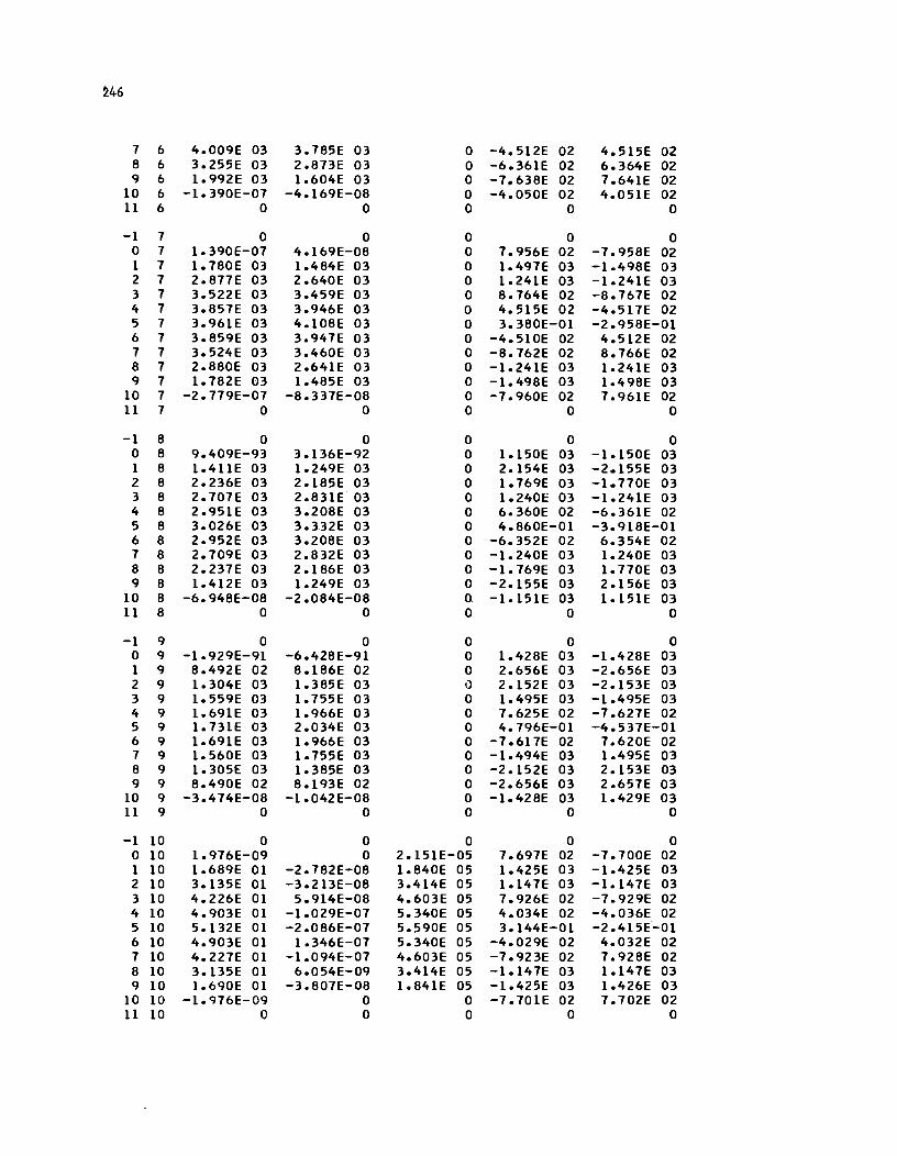
~46
7 6 4.009E 03 3.785E 03 0 -4.512E 02 4.515E 02 8 6 3.255E 03 2.873E 03 0 -6.361E 02 6.364E 02 9 6 1.992E 03 1.604E 03 0 -7 .. 638E 02 7.641E 02
10 6 -1.390E-07 -4.169E-08 0 -4.050E 02 4.051E 02 11 6 0 0 0 0 0
-1 7 0 0 0 0 0 0 7 1.390f-07 4.169E-08 0 7.956E 02 -7.958E 02 1 7 1.780E 03 1.484E 03 0 1.497E 03 -1.498E 03 2 7 2.877E 03 2.640E 03 0 1.24lE 03 -1.24lE 03 3 7 3.522E 03 3.459E 03 0 8.764E 02 -8.767E 02 4 7 3.857E 03 3.946E 03 0 4.515E 02 -4.517E 02 5 7 3.96lE 03 4.108E 03 0 3.380E-01 -2.958E-01 6 7 3.859E 03 3.947E 03 0 -4.510E 02 4.512E 02 7 7 3.524E 03 3.460E 03 0 -8.762E 02 8.766E 02 8 7 2.880E 03 2.64lE 03 0 -1.241E 03 1.241E 03 9 7 1.782E 03 1.485E 03 0 -1.498E 03 1.498E 03
10 7 -2.779E-07 -8.337E-08 0 -7.960E 02 7.961E 02 11 7 0 0 0 0 0
-1 8 0 0 0 0 0 0 8 9.409E-93 3.136E-92 0 1.150E 03 -1.150E 03 1 8 1.41lE 03 1.249E 03 0 2.154E 03 -2.155E 03 2 8 2.236E 03 2.185E 03 0 1.769E 03 -1.770E 03 3 8 2.707E 03 2.831E 03 0 1.240E 03 -1.241E 03 4 8 2.95lE 03 3.208E 03 0 6.360E 02 -6.36lE 02 5 8 3.026E 03 3.332E 03 0 4.860E-01 -3.918E-01 6 8 2.952E 03 3.208E 03 0 -6.352E 02 6.354E 02 7 8 2.709E 03 2.832E 03 0 -1.240E 03 1.240E 03 8 8 2.237E 03 2.186E 03 0 -1.769E 03 1.770E 03 9 8 1.412E 03 1.249E 03 0 -2.155E 03 2.156E 03
10 8 -6.948E-08 -2.084E-08 0 -1.15lE 03 1.151E 03 11 8 0 0 0 0 0
-1 9 0 0 0 0 0 0 9 -1.929E-91 -6.428E-91 0 1.428E 03 -1.428E 03 1 9 8.492E 02 8.186E 02 0 2.656E 03 -2.656E 03 2 9 1.304E 03 1.385E 03 I) 2.152E 03 -2.153E 03 3 9 1.559E 03 1.755E 03 0 1.495E 03 -1.495E 03 4 9 1.69lE 03 1.966E 03 0 7.625E 02 -7.627E 02 5 9 1.731E 03 2.034E 03 0 4.796E-01 -4.537E-01 6 9 1.69lE 03 1.966E 03 0 -7.617E 02 7.620E 02 7 9 1.560E 03 1.755E 03 0 -1.494E 03 1.495E 03 8 9 1.305E 03 1.385E 03 0 -2.152E 03 2.153E 03 9 9 8.490E 02 8.193E 02 0 -2.656E 03 2.657E 03
10 9 -3.474E-08 -1.042E-08 0 -1.428E 03 1.429E 03 11 9 0 0 0 0 0
-1 10 0 0 0 0 0 0 10 1.976E-09 0 2.15lE-05 7.697E 02 -7.700E 02 1 10 1.689E 01 -2.782E-08 1.840E 05 1.425E 03 -1.425E 03 2 10 3.135E 01 -3.213E-08 3.414E 05 1.147E 03 -1.147E 03 3 10 4.226E 01 5.914E-08 4.603E 05 7.926E 02 -7.929E 02 4 10 4.903E 01 -1.029E-07 5.340E 05 4.034E 02 -4.036E 02 5 10 5.132E 01 -2.086E-07 5.590E 05 3.144E-01 -2.415E-01 6 10 4.903E 01 1.346E-07 5.340E 05 -4.029E 02 4.032E 02 7 10 4.227E 01 -1.094E-07 4.603E 05 -7.923E 02 7.928E 02 8 10 3.135E 01 6.054E-09 3.414E 05 -1.147E 03 1.147E 03 9 10 1.690E 01 -3.807E-08 1.841E 05 -1.425E 03 1.426E 03
10 10 -1.976E-09 0 0 -7.70lE 02 7.702E 02 11 10 0 0 0 0 0
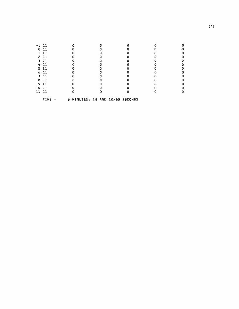
241
-1 11 0 0 0 0 0 0 11 0 0 0 0 0 1 11 0 0 0 0 0 2 11 0 0 0 0 0 3 11 0 0 0 0 0 4 11 0 0 0 0 0 5 11 0 0 0 0 0 6 11 0 0 0 0 0 1 11 0 0 0 0 0 8 11 0 0 0 0 0 9 11 0 0 0 0 0
10 11 0 0 0 0 0 11 11 0 0 0 0 0
TIME = 3 MINUTES, 18 AND 10/60 SECONDS
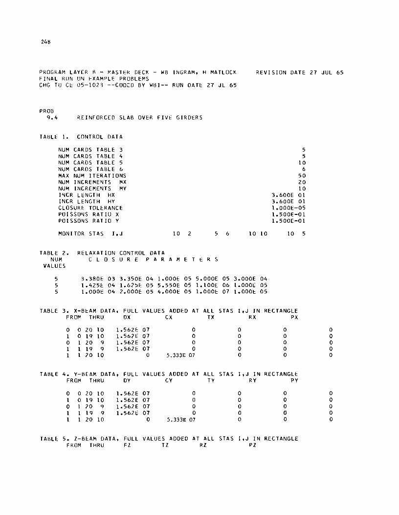
248
PROGRAM LAYER B - ~ASTER DECK - WB INGRAM, H MATLOCK FINAL KUN ON EXAMPLE PROBLEMS
REVISION DATE 27 JUL 65
CHG TO CE OS-1023 --CODED BY WBI-- RUN DATE 27 JL 6S
PRO[3 9.4 REINFORCED SLAB OVER FIVE GIRDERS
TABLE 1. CONTROL DATA
NUM CARDS TABLE 3 NUM CARDS TABLE 4 NUM CARDS TABLE S NUM CARDS TABLE 6 MAX NUM ITERATIONS NUM INCREMENTS MX NUM INCREMENTS MY INCR LENGTH HX INCR LENGTH HY CLOSURE TOLERANCE POISSONS RATIO X POISSONS RAT 10 Y
MONITOR STAS I,J 10 2 S 6
TABLE 2. RELAXATION CONTROL DATA NUM C LOS U R E PAR A MET E R S
VALUES
S 3.380E 03 3.3S0E 04 1.000E OS S.OOOE OS S 1.42SE 04 1.625E OS S.SSOE OS 1.100E 06 S 1.000E 04 2.000E OS 4.000E OS 1.000E 07
TABLE 3. X-Bl::AM DATA, FULL VALUES ADDED AT ALL STAS FROM THRU OX CX TX
0 0 20 10 1.S62E 07 0 1 0 19 10 1.S62E 07 0 0 1 20 9 1.S62E 07 0 1 1 19 9 1.S62E 07 0 1 1 20 10 0 5.333E 07
TABLE 4. Y-BEAM DATA, FULL VALUES ADDED AT ALL STAS FROM THRU DY CY TY
0 0 20 10 1.S62E 07 0 1 0 19 10 1.S62E 07 0 0 1 20 9 1.S62E 07 0 1 1 19 9 1.S62E 07 0 1 1 20 10 0 5.333E 07
TABLE S. I-BEAM DATA, FULL VALUES ADDED AT ALL STAS FROM THRU Fl Tl RI
S 5
10 6
SO 20 10
3.600E 01 3.600E 01 1.000E-OS 1.S00E-Ol 1.S00[-01
10 10 10 S
3.000E 04 1.000E OS 1.000E OS
I ,J IN RECTANGLE RX PX
0 0 0 0 0 0 0 0 0 0
I , J IN RECTANGLE RY PY
0 0 0 0 0 0 0 0 0 0
I ,J IN RECTANGLE PI
0 0 0 0 0
0 0 0 0 0
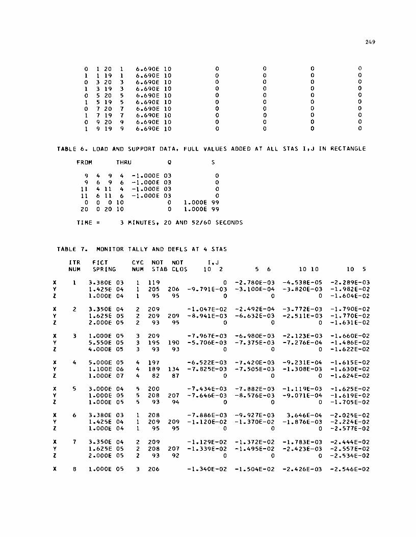
249
0 1 20 1 6.690E 10 0 0 0 0 1 1 19 1 6.690E 10 0 0 0 0 0 3 20 3 6.690E 10 0 0 0 0 1 3 19 3 6.690E 10 0 0 0 0 0 5 20 5 6.690E 10 0 0 0 0 1 5 19 5 6.690E 10 0 0 0 0 0 7 20 7 6.690E 10 0 0 0 0 1 7 19 7 6.690E 10 0 0 0 0 0 9 20 9 6.690E 10 0 0 0 0 1 9 19 9 6.690E 10 0 0 0 0
TABLE 6. LOAD AND SUPPORT DATA, FULL VALUES ADDED AT ALL STAS I, J IN RECTANGLE
FROM THRU Q S
9 4 9 4 -1.000E 03 0 9 6 9 6 -1.000E 03 0
11 4 11 4 -1.000E 03 0 11 6 11 6 -1.000E 03 0
0 0 0 10 0 1.000E 99 20 0 20 10 0 1.000E 99
TIME 3 MINUTES. 20 AND 52/60 SECONDS
TABLE 7. MONITOR TALLY AND DEHS AT 4 STAS
ITR FICT CYC NOT NOT I.J NUM SPRING NUM STAB CLOS 10 2 5 6 10 10 10 5
X 1 3.380E 03 1 119 0 -2.780E-03 -4.538E-05 -2.289E-03 Y 1.425E 04 1 205 206 -9.791E-03 -3.100E-04 -3.820E-03 -1.982E-02 Z 1.000E 04 1 95 95 0 0 0 -1.604E-02
X 2 3.350E 04 2 209 -1.047E-02 -2.492E-04 -3.772E-03 -1.790E-02 Y 1.625E 05 2 209 209 -8.941E-03 -6.632E-03 -2.51lE-03 -1.770E-02 Z 2.000E 05 2 93 95 0 0 0 -1.631E-02
X 3 1.000E 05 3 209 -7.967E-03 -6.980E-03 -2.123E-03 -1.660E-02 Y 5.550E 05 3 195 190 -5.706E-03 -7.375E-03 -7.276E-04 -1.486E-02 Z 4.000E 05 3 93 93 0 0 0 -1.622E-02
X 4 5.000E 05 4 197 -6.522E-03 -7.420E-03 -9.231E-04 -1.615E-02 Y 1.100E 06 4 189 134 -7.825E-03 -7.505E-03 -1.308E-03 -1.630E-02 Z 1.000E 07 4 82 87 0 0 0 -1.624E-02
X 5 3.000E 04 5 200 -7.434E-03 -7.882E-03 -1.119E-03 -1.625E-02 Y 1.000E 05 5 208 207 -7.646E-03 -8.576E-03 -9.071E-04 -1.619E-02 Z 1.000E 05 5 93 94 0 0 0 -1.705E-02
X 6 3.380E 03 1 208 -7.886E-03 -9.927E-03 3.646E-04 -2.025E-02 Y 1.425E 04 1 209 209 -1.120E-02 -1.370E-02 -1.876E-03 -2.224E-02 Z 1.000E 04 1 95 95 0 0 0 -2.577E-02
X 7 3.350E 04 2 209 -1.129E-02 -1.372E-02 -1.783E-03 -2.444E-02 Y 1.625E 05 2 208 207 -1.339E-02 -1.495E-02 -2.423E-03 -2.557E-02 Z 2.000E 05 2 93 92 0 0 0 -2.534E-02
X 8 i.OOOE 05 3 206 -1.340E-02 -1.504E-02 -2.426E-03 -2.546E-02
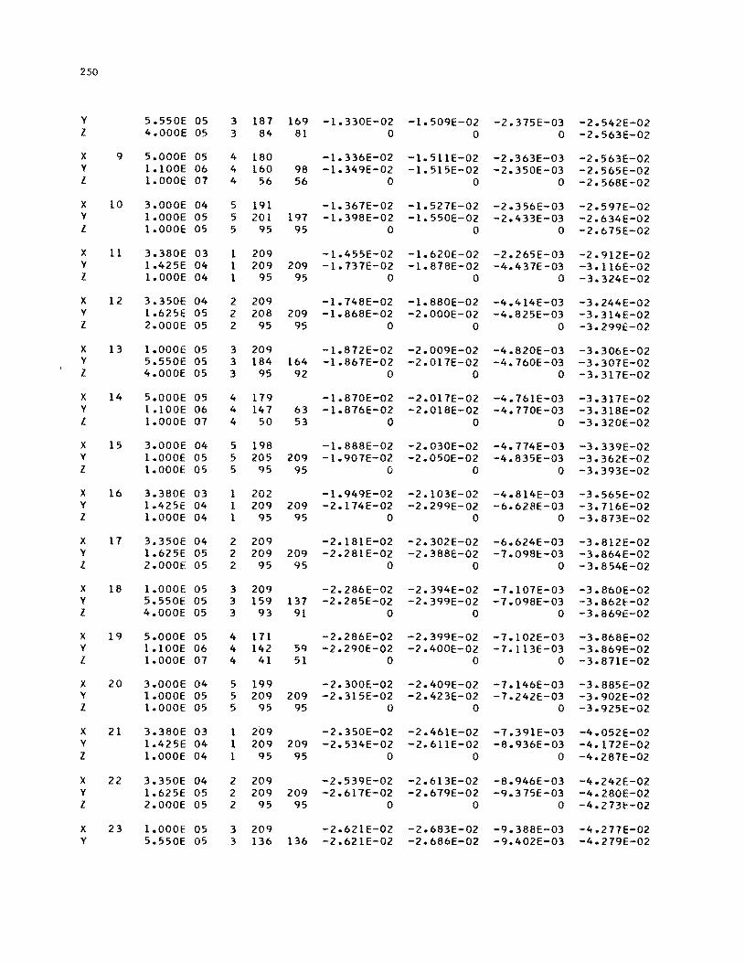
250
y 5.550E 05 3 187 169 -1.330E-02 -1.509E-02 -2.375E-03 -2.542E-02 Z 4.000E 05 3 84 81 0 0 0 -2.563E-02
X 9 5.000E 05 4 180 -1.336E-02 -1.511E-02 -2.363E-03 -2.563E-02 Y 1.100E 06 4 160 98 -1.349E-02 -1.515E-02 -2.350E-03 -2.565E-02 Z 1.000E 07 4 56 56 0 0 0 -2.568E-02
X 10 3.000E 04 5 191 -1.367E-02 -1.527E-02 -2.356E-03 -2.597E-02 Y I.OOOE 05 5 201 197 -1.398E-02 -1.550E-02 -2.433E-03 -2.634E-02 Z 1.000E 05 5 95 95 0 0 0 -2.675E-02
X 11 3.380E 03 1 209 -1.455E-02 -1.620E-02 -2.265E-03 -2.912E-02 Y 1.425E 04 I 209 209 -1.737E-02 -1.878E-02 -4.437E-03 -3.116E-02 Z 1.000E 04 1 95 95 0 0 0 -3.324E-02
X 12 3.350E 04 2 209 -1.748E-02 -1.880E-02 -4.414E-03 -3.244E-02 Y 1.625E 05 2 208 209 -1.868E-02 -2.000E-02 -4.825E-03 -3.314E-02 Z 2.000E 05 2 95 95 0 0 0 -3.299E-02
X 13 1.000E 05 3 209 -1.872E-02 -2.009E-02 -4.820E-03 -3.306E-02 Y 5.550E 05 3 184 164 -1.867E-02 -2.017E-02 -4.760E-03 -3.307E-02 Z 4.000E 05 3 95 92 0 0 0 -3.317E-02
X 14 5.000E 05 4 179 -1.870E-02 -2.017E-02 -4.76IE-03 -3.317E-02 Y 1.100E 06 4 147 63 -1.876E-02 -2.018E-02 -4.770E-03 -3.318E-02 Z I.OOOE 07 4 50 53 0 0 0 -3.320E-02
X 15 3.000E 04 5 198 -1.888E-02 -2.030E-02 -4.774E-03 -3.339E-02 Y I.OOOE 05 5 205 209 -1.907E-02 -2.050E-02 -4.835E-03 -3.362E-02 1 1.000E 05 5 95 95 0 0 0 -3.393E-02
X 16 3.380E 03 1 202 -1.949E-02 -2.103E-02 -4.814E-03 -3.565E-02 Y 1.425E 04 1 209 209 -2.174E-02 -2.299E-02 -6.628E-03 -3.716E-02 Z 1.000E 04 1 95 95 0 0 0 -3.873E-02
X 17 3.350E 04 2 209 -2.181E-02 -2.302E-02 -6.624E-03 -3.812E-02 Y 1.625E 05 2 209 209 -2.281E-02 -2.388E-02 -7.098E-03 -3.864E-02 Z 2.000E 05 2 95 95 0 0 0 -3.854E-02
X 18 1.000E 05 3 209 -2.286E-02 -2.394E-02 -7.107E-03 -3.860E-02 Y 5.550E 05 3 159 137 -2.285E-02 -2.399E-02 -7.098E-03 -3.862E-02 Z 4.000E 05 3 93 91 0 0 0 -3.869E-02
X 19 5.000E 05 4 171 -2.286E-02 -2.399E-02 -7.102E-03 -3.868E-02 Y I.IOOE 06 4 142 59 -2.290E-02 -Z.400E-02 -7.I13E-03 -3.869E-02 Z I.OOOE 07 4 41 51 0 0 0 -3.871E-02
X 20 3.000E 04 5 199 -2.300E-02 -2.409E-02 -7.146E-03 -3.885E-02 Y 1.000E 05 5 209 209 -2.315E-02 -2.423E-02 -7.242E-03 -3.902E-02 Z 1.000E 05 5 95 95 0 0 0 -3.925E-02
X 21 3.380E 03 1 209 -2.350E-02 -2.461E-02 -7.391E-03 -4.052E-02 Y 1.425E 04 I 209 209 -2.534E-02 -2.61IE-02 -8.936E-03 -4.172E-02 Z 1.000E 04 I 95 95 0 0 0 -4.287E-02
X 22 3.350E 04 2 209 -2.539E-02 -2.613E-02 -8.946E-03 -4.242E-02 Y 1.625E 05 2 209 209 -2.617E-02 -Z.679E-02 -9.375E-03 -4.280E-02 Z 2.000E 05 2 95 95 0 0 0 -4.273E-02
X 23 1.000E 05 3 209 -2.621E-02 -2.683E-02 -9.388E-03 -4.277E-02 Y 5.550E 05 3 136 136 -2.621E-02 -Z.686E-02 -9.402E-03 -4.279E-02
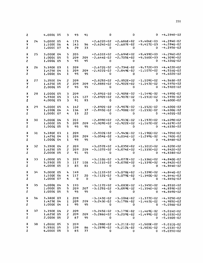
251
Z 4.000E 05 3 93 91 0 0 0 -4.284E-02
X 24 5.000E 05 4 173 -2.622E-02 -2.686E-02 -9.406E-03 -4.284E-02 Y 1.100E 06 4 143 56 -2.624E-02 -2.687E-02 -9.417E-03 -4.284E-02 Z 1.000E 07 4 29 33 0 0 0 -4.285E-02
X 25 3.000E 04 5 205 -2.631E-02 -2.694E-02 -9.459E-03 -4.296E-02 Y 1.000E 05 5 209 209 -2.644E-02 -2.705E-02 -9.560E-03 -4.309E-02 Z 1.000E 05 5 95 95 0 0 0 -4.326E-02
X 26 3.380E 03 1 209 -2.672E-02 -2.734E-02 -9.772E-03 -4.422E-02 Y 1.425E 04 1 209 209 -2.822E-02 -2.849E-02 -1.107E-02 -4.516E-02 Z 1.000E 04 1 95 95 0 0 0 -4.602E-02
X 27 3.350E 04 2 209 -2.825E-02 -2.852E-02 -1.109E-02 -4.568E-02 Y 1.625E 05 2 209 209 -2.888E-02 -2.902E-02 -1.147E-02 -4.597E-02 Z 2.000E 05 2 95 95 0 0 0 -4.592E-02
X 28 1.000E 05 3 209 -2.891E-02 -2.905E-02 -1.149E-02 -4.595E-02 Y 5.550E 05 3 124 127 -2.892E-02 -2.907E-02 -1.151E-02 -4.597E-02 Z 4.000E 05 3 91 83 0 0 0 -4.600E-02
X 29 5.000E 05 4 162 -2.892E-02 -2.907E-02 -1.152E-02 -4.600E-02 Y 1.100E 06 4 136 37 -2.893E-02 -2.908E-02 -1.153E-02 -4.600E-02 Z 1.000E 07 4 15 22 0 0 0 -4.601E-02
X 30 3.000E 04 5 201 -2.899E-02 -2.913E-02 -1.157E-02 -4.609E-02 Y 1.000E 05 5 209 209 -2.909E-02 -2.922E-02 -1.167E-02 -4.619E-02 Z 1.000E 05 5 95 95 0 0 0 -4.633E-02
X 31 3.380E 03 1 209 -2.932E-02 -?943E-02 -1.190E-02 -4.705E-02 Y 1.425E 04 1 209 209 -3.054E-02 -3.034E-02 -1.299E-02 -4.780E-02 Z 1.000E 04 1 95 95 0 0 0 -4.846E-02
X 32 3.350E 04 2 209 -3.057E-02 -3.035E-02 -1.301E-02 -4.820E-02 Y 1.625E 05 2 209 209 -3.107E-02 -3.074E-02 -1.335E-02 -4.842E-02 Z 2.000E 05 2 91 95 0 0 0 -4.838E-02
X 33 1.000E 05 3 209 -3.110E-02 -3.077E-02 -1.336E-02 -4.840E-02 Y 5.550E 05 3 117 108 -3.111E-02 -3.078E-02 -1.339E-02 -4.842E-02 Z 4.000E 05 3 85 81 0 0 0 -4.844E-02
X 34 5.000E 05 4 149 -3.111E-02 -3.078E-02 -1.339E-02 -4.844E-02 Y 1.100E 06 4 117 20 -3.112E-02 -3.079E-02 -1.340E-02 -4.844E-02 Z 1.000E 07 4 0 0 0 0 0 -4.845E-02
X 35 3.000E 04 5 193 -3.117E-02 -3.083E-02 -1.345E-02 -4.851E-02 Y 1.000E 05 5 209 207 -3.125E-02 -3.089E-02 -1.354E-02 -4.859E-02 Z 1.000E 05 5 95 95 0 0 0 -4.869E-02
X 36 3.380E 03 1 209 -3.143E-02 -3.106E-02 -1.377E-02 -4.925E-02 Y 1.425E 04 1 209 209 -3.243E-02 -3.178E-02 -1.467E-02 -4.985E-02 Z 1.000E 04 1 95 95 0 0 0 -5.036E-02
X 37 3.350E 04 2 209 -3.245E-02 -3.179E-02 -1.469E-02 -5.016E-02 Y 1.625E 05 2 209 209 -3.286E-02 -3.209E-02 -1.499E-02 -5.033E-02 Z 2.000E 05 2 87 95 0 0 0 -5.030E-02
X 38 1.000E 05 3 209 -3.288E-02 -3.211E-02 -1.500E-02 -5.031E-02 Y 5.550E 05 3 109 86 -3.289E-02 -3.212E-02 -1.503E-02 -5.033E-02 Z 4.000E 05 3 85 77 0 0 0 -5.035E-02
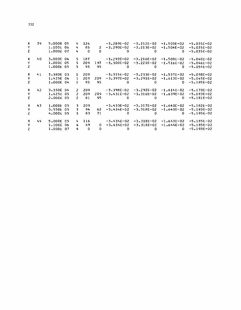
252
X 39 5.000E 05 4 126 -3.289E-02 -3.212E-02 -1.503E-02 -5.035E-02 Y 1.100E 06 4 85 2 -3.290E-02 -3.213E-02 -1.504E-02 -5.035E-02 Z 1.000E 07 4 0 0 0 0 0 -5.035E-02
X 40 3.000E 04 5 187 -3.293E-02 -3.216E-02 -1.508E-02 -5.040E-02 Y 1.000t 05 5 209 197 -3.300E-02 -3.221E-02 -1.516E-02 -5.046E-02 Z 1.000E 05 5 95 95 0 0 0 -5.054E-02
X 41 3.380E 03 1 209 -3.315E-02 -3.233E-02 -1.537E-02 -5.098£-02 Y 1.425E 04 1 209 209 -3.397E-02 -3.291E-02 -1.613E-02 -5.145E-02 Z 1.000E 04 1 95 95 0 0 0 -5.185E-02
X 42 3.350E 04 2 209 -3.398E-02 -3.292E-02 -1.614E-02 -5.170E-02 Y 1.625E 05 2 209 209 -3.431E-02 -3.316E-02 -1.639E-02 -5.183E-02 Z 2.0001:: 05 2 81 95 0 0 0 -5.181E-02
X 43 1.000E 05 3 209 -3.433E-02 -3.317E-02 -1.640E-02 -5.182E-02 Y 5.550E 05 3 94 62 -3.434E-02 -3.318E-02 -1.643E-02 -5.183E-02 Z 4.000E 05 3 83 71 0 0 0 -5.185E-02
X 44 5.000E 05 4 116 -3.434£-02 -3.318E-02 -1.643E-02 -5.185E-02 Y 1.100E 06 4 49 0 -3.434E-02 -3.318E-02 -1.644E-02 -5.185E-02 Z 1.000E 07 4 0 0 0 0 0 -5.185E-02
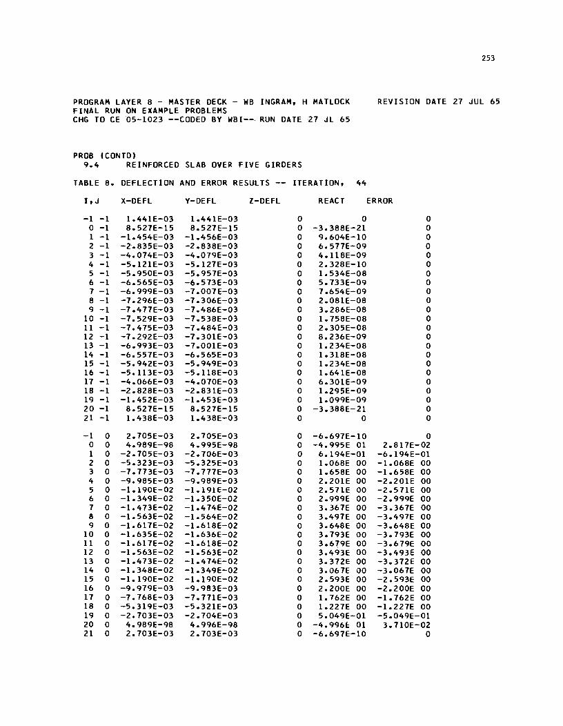
PROGRAM LAYER 8 - MASTER DECK - WB INGRAM, H MATLOCK FINAL RUN ON EXAMPLE PROBLEMS CHG TO CE 05-1023 --CODED BY WBI-- RUN DATE 27 JL 65
PROB (CONTD) 9.4 REINFORCED SLAB OVER FIVE GIRDERS
TABLE 8. DEflECTION AND ERROR RESULTS -- ITERATION, 44
I,J X-DEFL Y-DEFL l-DEFL REACT
-1 -1 1.441E-03 1.441E-03 0 0 0 -1 8.527E-15 8.527E-15 0 -3.388E-21 1 -1 -1.454E-03 -1.456E-03 0 9.604E-10 2 -1 -2-.835E-03 -2.838E-03 0 6. 577E-09 3 -1 -4.074E-03 -4.079E-03 0 4.1l8E-09 4 -1 -5.121E-03 -5.127E-03 0 2.328E-10 5 -1 -5.950E-03 -5.957E-03 0 1.534E-08 6 -1 -6.565E-03 -6.573E-03 0 5.733E-09 7 -1 -6.999E-03 -7.001E-03 0 7.654E-09 8 -1 -7.296E-03 -7.306E-:-03 0 2.081E-08 9 -1 -7.477E-03 -7.486E-03 0 3.286E-08
10 -1 -7.529E-03 -7.538E-03 0 1.758E-08 11 -1 -7.475E-03 -7.484E-03 0 2.305E-08 12 -1 -7.292E-03 -7.301E-03 0 8.236E-09 13 -1 -6.993E-03 -7.001E-03 0 1.234E-08 14 -1 -6.557E-03 -6.565E-03 0 1.318E-08 15 -1 -5.942E-03 -5.949E-03 0 1.B4E-08 16 -1 -5.1l3E-03 -5.1l8E-03 0 1.641E-08 17 -1 -4.066E-03 -4.070E-03 0 6.301E-09 18 -1 -2.828E-03 -2.831E-03 0 1.295E-09 19 -1 -1.452E-03 -1.453E-03 0 1.099E-09 20 -1 8.527E-15 8.527E-15 0 -3.388E-21 21 -1 1.438E-03 1.438E-03 0 0
-1 0 2.705E-03 2.705E-03 0 -6.697E-10 0 0 4.989E-98 4.995E-98 0 -4.995E 01 1 0 -2.705E-03 -2.706E-03 0 6.194E-01 2 0 -5.323E-03 -5.325E-03 0 1.068E 00 3 0 -7.773E-03 -7.777E-03 0 1.658E 00 4 0 -9.985E-03 -9.989E-03 0 2.201E 00 5 0 -1.190E-02 -1.191E-02 0 2.571E 00 6 0 -1.349E-02 -1.350E-02 0 2.999E 00 7 0 -1.473E-02 -1.474E-02 0 3.367E 00 8 0 -1.563E-02 -1.564E-02 0 3.497E 00 9 0 -1.617E-02 -1.618E-02 0 3.648E 00
10 0 -1.635E-02 -1.636E-02 0 3.793E 00 11 0 -1.617E-02 -1.618E-02 0 3.679E 00 12 0 -1.563E-02 -1.563E-02 0 3.493E 00 13 0 -1.473E-02 -1.474E-02 0 3.372E 00 14 0 -1.348E-02 -1.349E-02 0 3.067E 00 15 0 -1.190E-02 -1.190E-02 0 2.593E 00 16 0 -9.979E-03 -9.983E-03 0 2.200E 00 17 0 -7.768E-03 -7.771 E-03 0 1.762E 00 18 0 -5.319E-03 -5.321E-03 0 1.227E 00 19 0 -2.703E-03 -2.704E-03 0 5.049E-01 20 0 4.989E-98 4.996E-98 0 -4.996E 01 21 0 2.703E-03 2.703E-03 0 -6.697E-10
253
REVISION DATE 27 JUL 65
ERROR
0 0 0 0 0 0 0 0 0 0 0 0 0 0 0 0 0 0 0 0 0 0 0
0 2.817E-02
-6.194E-01 -1.068E 00 -1.658E 00 -2.201E 00 -2.51lE 00 -2.999E 00 -3.367E 00 -3.497E 00 -3.648E 00 -3.793E 00 -3.679E 00 -3.493E 00 -3.372E 00 -3.067E 00 -2.593E 00 -2.200E 00 -1.762E 00 -1.227E 00 -5.049E-01
3.1l0E-02 0

B4
-1 1 3.968E-03 3.968E-03 3.969E-03 -1.658E-07 0 0 1 -2.894E-97 -2.894E-97 -2.895E-97 2.895E 02 -3.682E-02 1 1 -3.968E-03 -3.969E-03 -3.969E-03 1.093E 00 -1.093E 00 2 1 -7.838E-03 -7.838E-03 -7.839E-03 2.161E 00 -2.161E 00 3 1 -1.151E-02 -1.151E-02 -1.151E-02 3.179E 00 -3.1 HE 00 4 1 -1.489E-02 -1.490E-02 -1.490E-02 4.120E 00 -4.120E 00 5 1 -1.791E-02 -1.791E-02 -1.791E-02 4.966E 00 -4.966E 00 6 1 -2.047E-02 -2.047E-02 -2.047E-02 5.697E 00 -5.697E 00 7 1 -2.252E-02 -2.252E-02 -2.253E-02 6.282E 00 -6.282E 00 8 1 -2.402E-02 -2.402E-02 -2.402E-02 6.707E 00 -6.707E 00 9 1 -2.493E-02 -2.493E-02 -2.493E-02 6.974E 00 -6.974E 00
10 1 -2.523E-02 -2.523E-02 -2.524E-02 7.069E 00 -7.069E 00 11 1 -2.493E-02 -2.493E-02 -2.493E-02 6.979E 00 -6.979E 00 12 1 -2.402E-02 -2.402E-02 -2.402E-02 6.722E 00 -6.722E 00 13 1 -2.252E-02 -2.252E-02 -2.253E-02 6.312E 00 -6.312E 00 14 1 -2.047E-02 -2.047E-02 -2.047E-02 5.738E 00 -5.738E 00 15 1 -1.790E-02 -1.790E-02 -1.791E-02 5.016E 00 -5.016E 00 16 1 -1.489E-02 -1.489E-02 -1.489E-02 4.180E 00 -4.180E 00 17 1 -1.151E-02 -1.151E-02 -1.151E-02 3.241E 00 -3.241E 00 18 1 -7.836E-03 -7.836E-03 -7.837E-03 2.205E 00 -2.205E 00 19 1 -3.968E-03 -3.968E-03 -3.968E-03 1.104E 00 -1.104E 00 20 1 -2.891E-97 -2.892E-97 -2.892E-97 2.892E 02 -2.659E-02 21 1 3.968E-03 3.968E-03 3.968E-03 -2.740E-09 0
-1 2 5.242E-03 5.242E-03 0 -2.740E-09 0 0 2 -1.332E-98 -1.324E-98 0 1.321E 01 6.799E-02 1 2 -5.242E-03 -5.243E-03 0 4.962E-Ol -4.962E-Ol 2 2 -1.037E-02 -1.038E-02 0 9.229E-Ol -9.229E-Ol 3 2 -1.529E-02 -1.529E-02 0 1.415E 00 -1.415E 00 4 2 -1.987E-02 -1.987E-02 0 1.811E 00 -1.811E 00 5 2 -2.401E-02 -2.401E-02 0 2.062E 00 -2.062E 00 6 2 -2.759E-02 -2.759E-02 0 2.483E 00 -2.483E 00 7 2 -3.050E-02 -3.050E-02 0 2.787E 00 -2.787E 00 8 2 -3.262E-02 -3.262E-02 0 2.796E 00 -2.796E 00 9 2 -3.388E-02 -3.389E-02 0 2.966E 00 -2.966E 00
10 2 -3.434E-02 -3.434E-02 0 3.151E 00 -3.151E 00 11 2 -3.388E-02 -3.389E-02 0 2.953E 00 -2.953E 00 12 2 -3.262E-02 -3.262E-02 0 2.77 7E 00 -2.777E 00 13 2 -3.050E-02 -3.050E-02 0 2.793E 00 -2.793E 00 14 2 -2.759E-02 -2.759E-02 0 2.512E 00 -2.512E 00 15 2 -2.400E-02 -2.401E-02 0 2.025E 00 -2.025E 00 16 2 -1.987E-02 -1.987E-02 0 1.787E 00 -1.787E 00 17 2 -1.528E-02 -1.529E-02 0 1.487E 00 -1.487E 00 18 2 -1.037E-02 -1.038E-02 0 8.506E-Ol -8.506E-Ol 19 2 -5.242E-03 -5.243E-03 0 4.539E-Ol -4.539E-Ol 20 2 -1.340E-98 -1.325E-98 0 1.325E 01 7.429E-02 21 2 5.242E-03 5.242E-03 0 -2.240E-93 0
-1 3 6.353E-03 6.353E-03 6.354E-03 -3.315E-07 0 0 3 -3.566E-97 -3.565E-97 -3.567E-97 3.567E 02 -7.711E-02 1 3 -6.353E-03 -6.354E-03 -6.354E-03 1.241E 00 -1.241E 00 2 3 -1.259E-02 -1.259E-02 -1.259E-02 2.439E 00 -2.439E 00 3 3 -1.859E-02 -1.859E-02 -1.860E-02 3.556E 00 -3.556E 00 4 3 -2.424E-02 -2.424E-02 -2.424E-02 4.5741:: 00 -4.574E 00 5 3 -2.940E-02 -2.940E-02 -2.940E-02 5.485E 00 -5.485E 00 6 3 -3.394E-02 -3.394E-02 -3.395E-02 6.270E 00 -6.270E 00 7 3 -3.773E-02 -3.773E-02 -3.773E-02 6.896E 00 -6.896E 00 8 3 -4.061E-02 -4.061E-02 -4.061E-02 7.3501:: 00 -7.350E 00 9 3 -4.242E-02 -4.242E-02 -4.243E-02 7.630E 00 -7.630E 00
10 3 -4.304E-02 -4.304E-02 -4.304E-02 7.722E 00 -7.722E 00
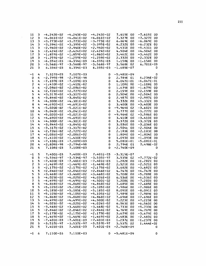
255
11 3 -4.242E-02 -4.243E-02 -4.243E-02 7.615E 00 -7.615E 00 12 3 -4.061E-02 -4.061E-02 -4.061E-02 7.327E 00 -7.327E 00 13 3 -3.773E-02 -3.773E-02 -3.773E-02 6.869E 00 -6.869E 00 14 3 -3.394E-02 -3.395E-02 -3.395E-02 6.232E 00 -6.232E 00 15 3 -2.940E-02 -2.940E-02 -2.940E-02 5.431E 00 -5.4311: 00 16 3 -2.424E-02 -2.424E-02 -2.424E-02 4.504E 00 -4.504E 00 17 3 -1.859E-02 -1.859E-02 -1.860E-02 3.462E 00 -3.462E 00 18 3 -1.259E-02 -1.259E-02 -1.259E-02 2.332E 00 -2.332E 00 19 3 -6.354E-03 -6.354E-03 -6.355E-03 1.158E 00 -1.158E 00 20 3 -3.568E-97 -3.568E-97 -3.568E-97 3.568E 02 6.701E-03 21 3 6.354E-03 6.354E-03 6.355E-03 -1.685E-07 0
-1 4 7.107E-03 7.107E-03 0 -5.481E-09 0 0 4 -2.799E-98 -2.791E-98 0 2.789E 01 6.234E-02 1 4 -7.107E-03 -7.109E-03 0 6.047E-01 -6.047E-01 2 4 -1.410E-02 -1.410E-02 0 1.108E 00 -1.108E 00 3 4 -2.086E-02 -2.086E-02 0 1.679E 00 -1.679E 00 4 4 -2.726E-02 -2.727E-02 0 2.159E 00 -2.159E 00 5 4 -3.317E-02 -3.317E-02 0 2.504E 00 -2.504E 00 6 4 -3.844E-02 -3.845E-02 0 2.987E 00 -2.987E 00 7 4 -4.300E-02 -4.301E-02 0 3.332E 00 -3.332E 00 8 4 -4.690E-02 -4.691E-02 0 3.400E 00 -3.400E 00 9 4 -5.020E-02 -5.021E-02 0 -9.964E 02 -3.602E 00
10 4 -5.040E-02 -5.041E-02 0 3.777E 00 -3.777E 00 11 4 -5.020E-02 -5.021E-02 0 -9.964E 02 -3.586E 00 12 4 -4.690E-02 -4.691E-02 0 3.410E 00 -3.410E 00 13 4 -4.300E-02 -4.301E-02 0 3.372E 00 -3.372E 00 14 4 -3.844E-02 -3.845E-02 0 3.036E 00 -3.036E 00 15 4 -3.317E-02 -3.317E-02 0 2.5041: 00 -2.504E 00 16 4 -2.726E-02 -2.727E-02 0 2.183E 00 -2.183E 00 17 4 -2.086E-02 -2.086E-02 0 1.804E 00 -1.804E 00 18 4 -1.410E-02 -1.410E-02 0 1.093E 00 -1.093E 00 19 4 -7.108E-03 -7.109E-03 0 5.081E-01 -5.081E-01 20 4 -2.809E-98 -2.794E-98 0 2.794E 01 7.498E-02 21 4 7.108E-03 7.108E-03 0 -2.740E-09 0
-1 5 7.400E-03 7.400E-03 7.401E-03 -3.315E-07 0 0 5 -3.534E-97 -3.534E-97 -3.535E-97 3.535E 02 -7.772E-02 1 5 -7.400E-03 -7.401E-03 -7.401E-03 1.282E 00 -1.282E 00 2 5 -1.469E-02 -1.469E-02 -1.469E-02 2.521E 00 -2.521E 00 3 5 -2.175E-02 -2.175E-02 -2.175E-02 3.682E 00 -3.682E 00 4 5 -2.846E-02 -2.846E-02 -2.846E-02 4.747E 00 -4.747E 00 5 5 -3.468E-02 -3.468E-02 -3.468E-02 5.708E 00 -5.708E 00 6 5 -4.025E-02 -4.025E-02 -4.026E-02 6.536E 00 -6.536E 00 7 5 -4.499E-02 -4.499E-02 -4.500E-02 7.200E 00 -7.200E 00 8 5 -4.868E-02 -4.868E-02 -4.868E-02 7.685E 00 -7.685E 00 9 5 -5.105E-02 -5.105E-02 -5.105E-02 7.986E 00 -7.986E 00
10 5 -5.185E-02 -5.185E-02 -5.185E-02 8.091E 00 -8.091E 00 11 5 -5.105E-02 -5.105E-02 -5.105E-02 7.989E 00 -7.989E 00 12 5 -4.868E-02 -4.868E-02 -4.868E-02 7.696E 00 -7.696E 00 13 5 -4.499E-02 -4.499E-02 -4.500E-02 7.223E 00 -7.223E 00 14 5 -4.025E-02 -4.025E-02 -4.026E-02 6.563E 00 -6.563E 00 15 5 -3.468E-02 -3.468E-02 -3.468E-02 5.733E 00 -5.733E 00 16 5 -2.846E-02 -2.846E-02 -2.846E-02 4.769E 00 -4.769E 00 17 5 -2.175E-02 -2.175E-02 -2.175E-02 3.679E 00 -3.679E 00 18 5 -1.469E-02 -1.469E-02 -1.469E-02 2.483E 00 -2.483E 00 19 5 -7.401E-03 -7.401E-03 -7.401E-03 1.237E 00 -1.237E 00 20 5 -3.537E-97 -3.537E-97 -3.537E-97 3.537E 02 1.444E-02 21 5 7.401E-03 7.401E-03 7.401E-03 -2.740E-09 0
-1 6 7.110E-03 7.110E-03 0 -5.481E-09 0
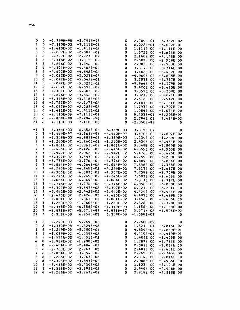
~56
0 6 -2.799E-98 -2.791E-98 0 2.789E 01 6.352E-02 1 6 -7.110E-03 -7.111E-03 0 6.022E-01 -6.022E-01 2 6 -1.410E-02 -1.411E-02 0 l.lllE 00 -l.l11E 00 3 6 -2.087E-02 -2.087E-02 0 1.673E 00 -1.673E 00 4 6 -2.727E-02 -2.727E-02 0 2.148E 00 -2.148E 00 5 6 -3.318E-02 -3.318E-02 0 2.509E 00 -2.509E 00 6 6 -3.846E-02 -3.846E-02 0 2.983E 00 -2.983E 00 7 6 -4.301E-02 -4.302E-02 0 3.314E 00 -3.314E 00 8 6 -4.692E-02 -4.692[-02 0 3.402E 00 -3.402E 00 9 6 -5.022E-02 -5.023E-02 0 -9.964E 02 -3.605E 00
10 6 -5.042E-02 -5.042E-02 0 3.757E 00 -3.757E 00 11 6 -5.022E-02 -5.023E-02 0 -9.964E 02 -3.579E 00 12 6 -4.692E-02 -4.692E-02 0 3.420E 00 -3.420E 00 13 6 -4.301E-02 -4.302E-02 0 3.359E 00 -3.359E 00 14 6 -3.846E-02 -3.846E-02 0 3.021E 00 -3.021E 00 15 6 -3.318E-02 -3.318E-02 0 2.512E 00 -2.512E 00 16 6 -2.727E-02 -2.727E-02 0 2.181E 00 -2.181E 00 17 6 -2.087E-02 -2.087E-02 0 1.797E 00 -1.797E 00 18 6 -1.411E-02 -1.411E-02 0 1.084E 00 -1.084E 00 19 6 -7.11OE-03 -7.111E-03 0 5.203E-01 -5.203E-01 20 6 -2.809E-98 -2.794E-98 0 2.794E 01 7.474E-02 21 6 7.110E-03 7.110E-03 0 -2.368E-93 0
-1 7 6.358E-03 6.358E-03 6.359E-03 -3.315E-07 0 0 7 -3.569E-97 -3.568E-97 -3.570E-97 3.570E 02 -7.897E-02 1 7 -6.358E-03 -6.358E-03 -6.359E-03 1.239E 00 -1.239E 00 2 7 -1.260E-02 -1.260E-02 -1.260E-02 2.434E 00 -2.434E 00 3 7 -1.861E-02 -1.861E-02 -1.861E-02 3.549E 00 -3.549E 00 4 7 -2.426E-02 -2.426E-02 -2.426E-02 4.565E 00 -4.565E 00 5 7 -2.942E-02 -2.942E-02 -2.942E-02 5.476E 00 -5.476E 00 6 7 -3.3,97E-02 -3.397E-02 -3.397E-02 6.259E 00 -6.259E 00 7 7 -3.776E-02 -3.776E-02 -3.776E-02 6.884E 00 -6.884E 00 8 7 -4.064E-02 -4.064E-02 -4.064E-02 7.338E 00 -7.338E 00 9 7 -4.245E-02 -4.245E-02 -4.246E-02 7.617E 00 -7.617E 00
10 7 -4.306E-02 -4.307E-02 -4.307E-02 7.709E 00 -7.709E 00 11 7 -4.245E-02 -4.245E-02 -4.246E-02 7.603E 00 -7.603E 00 12 7 -4.064E-02 -4.064E-02 -4.064E-02 7.317E 00 -7.317E 00 13 7 -3.776E-02 -3.776E-02 -3.776E-02 6.858E 00 -6.858E 00 14 7 -3.397E-02 -3.397E-02 -3.397E-02 6.221E 00 -6.221E 00 15 7 -2.942E-02 -2.942E-02 -2.942E-02 5.424E 00 -5.424E 00 16 7 -2.426E-02 -2.426E-02 -2.426[-02 4.499E 00 -4.499E 00 17 7 -1.861E-02 -1.861E-02 -1.861E-02 3.456E 00 -3.456E 00 18 7 -1.260E-p2 -1.260E-02 -1.260E-02 2.328[: 00 -2.328E 00 19 7 -6.358E-03 -6.358E-03 -6.359E-03 1.158E 00 -1.158E 00 20 7 -3.571 E-97 -3.571E-97 -3.571E-97 3.571E 02 -1.506E-02 21 7 6.358E-03 6.358E-03 6.359E-03 -1.658E-07 0
-1 8 5.249E-03 5.249E-03 0 -2.740E-09 0 0 8 -1.330E-98 -1.324E-98 0 1.321E 01 5.816E-02 1 8 -5.249E-03 -5.250E-03 0 4.839E-01 -4.839E-01 2 8 -1.039E-02 -1.039E-02 0 9.419E-01 -9.419E-01 3 8 -1.531E-02 -1.531E-02 0 1.405E 00 -1.405E 00 4 8 -1.989E-02 -1.990E-02 0 1.787E 00 -1.787E 00 5 8 -2.404E-02 -2.404E-02 0 2.087E 00 -2.087E 00 6 8 -2.763E-02 -2.763E-02 0 2.481[: 00 -2.481E 00 7 8 -3.054E-02 -3.054E-02 0 2.745E 00 -2.745E 00 8 8 -3.266E-02 -3.267E-02 0 2.814E 00 -2.814E 00 9 8 -3.393E-02 -3.393E-02 0 2.986E 00 -2.986E 00
10 8 -3.438E-02 -3.439E-02 0 3.103E 00 -3.103E 00 11 8 -3.393E-02 -3.393E-02 0 2.946E 00 -2.946E 00 12 8 -3.266E-02 -3.267E-02 0 2.818E 00 -2.818E 00
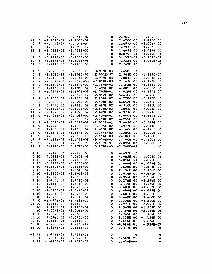
257
13 8 -3.054E-02 -3.054E-02 0 2.764E 00 -2.764E 00 14 8 -2.762E-02 -2.763E-02 0 2.478E 00 -2.478E 00 15 8 -2.404E-02 -2.404E-02 0 2.057E 00 -2.057E 00 16 8 -1.989E-02 -1.990E-02 0 1.793E 00 -1.793E 00 17 8 -1.531E-02 -1.53lE-02 0 1.469E 00 -1.469E 00 18 8 -1.039E-02 -1.039E-02 0 8.079E-01 -8.079E-01 19 8 -5.249E-03 -5.250E-03 0 5.155E-01 -5.155E-01 20 8 -1.335E-98 -1.323E-98 0 1.323E 01 6.080E-02 21 8 5.249E-03 5.249E-03 0 -2.243E-93 0
-1 9 3.978E-03 3.978E-03 3.979E-03 -1.658E-07 0 0 9 -2.902E-97 -2.90lE-97 -2.901E-97 2.901E 02 -1.715E-02 1 9 -3.978E-03 -3.978E-03 -3.979E-03 1.083E 00 -1.083E 00 2 9 -7.857E-03 -7.857E-03 -7.858E-03 2.143E 00 -2.143E 00 3 9 -1.154E-02 -1.154E-02 -1.154E-02 3.152E 00 -3.152E 00 4 9 -1.493E-02 -1.493E-02 -1.493E-02 4.085E 00 -4.085E 00 5 9 -1.795E-02 -1.795E-02 -1.795E-02 4.925E 00 -4.925E 00 6 9 -2.052E-02 -2.052E-02 -2.052E-02 5.648E 00 -5.648E 00 7 9 -2.258E-02 -2.258E-02 -2.258E-02 6.228E 00 -6.228E 00 8 9 -2.408E-02 -2.408E-02 -2.408E-02 6.652E 00 -6.652E 00 9 9 -2.499E-02 -2.499E-02 -2.499E-02 6.916E 00 -6.916E 00
10 9 -2.530E-02 -2.530E-02 -2.530E-02 7.008E 00 -7.008E 00 11 9 -2.499E-02 -2.499E-02 -2.499E-02 6.921E 00 -6.921E 00 12 9 -2.408E-02 -2.408E-02 -2.408E-02 6.669E 00 -6.669E 00 13 9 -2.258E-02 -2.258E-02 -2.258E-02 6.259E 00 -6.259E 00 14 9 -2.052E-02 -2.052E-02 -2.052E-02 5.689E 00 -5.689E 00 15 9 -1.795E-02 -1.795E-02 -1.795E-02 4.917E 00 -4.917E 00 16 9 -1.493E-02 -1.493E-02 -1.493E-02 4.148E 00 -4.148E 00 17 9 -1.154E-02 -1.154E-02 -1.154E-02 3.209E 00 -3.209E 00 18 9 -7.855E-03 -7.855E-03 -7.856E-03 2.186E 00 -2.186E 00 19 9 -3.917E-03 -3.917E-03 -3.978E-03 1.100E 00 -1.100E 00 20 9 -2.899E-97 -2.898E-97 -2.899E-97 2.899E 02 -1.906E-02 21 9 3.917E-03 3.917E-03 3.978E-03 -2.740E-09 0
-1 10 2.717E-03 2.717E-03 0 -6.697E-10 0 0 10 4.982E-98 4.982E-98 0 -4.982E 01 -1.093E-03 1 10 -2.717E-03 -2.718E-03 0 5.846E-01 -5.846E-01 2 10 -5.348E-03 -5.350E-03 0 1.069E 00 -1.069E 00 3 10 -7.810E-03 -7.813E-03 0 1.625E 00 -1.625E 00 4 10 -1.003E-02 -1.004E-02 0 2.136E 00 -2.136E 00 5 10 -1.196E-02 -1.196E-02 0 2.539E 00 -2.539E 00 6 10 -1.355E-02 -1.356E-02 0 2.954E 00 -2.954E 00 7 10 -1.480E-02 -1.481E-02 0 3.276E 00 -3.276E 00 8 10 -1.571E-02 -1.571E-02 0 3.439E 00 -3.439E 00 9 10 -1.625E-02 -1.626E-02 0 3.603E 00 -3.603E 00
10 10 -1.643E-02 -1.6'44E-02 0 3.698E 00 -3.698E 00 11 10 -1.625E-02 -1.626E-02 0 3.601E 00 -3.601E 00 12 10 -1.510E-02 -1.571E-02 0 3.460E 00 -3.460E 00 13 10 -1.480E-02 -1.48lE-02 0 3.300E 00 -3.300E 00 14 10 -1.355E-02 -1.356E-02 0 2.991E 00 -2.991E 00 15 10 -1.195E-02 -1.196E-02 0 2.565E 00 -2.565E 00 16 10 -1.003E-02 -1.003E-02 0 2.154E 00 -2.154E 00 17 10 -7.804E-03 -7.808E-03 0 1.765E 00 -1.765E 00 18 10 -5.344E-03 -5.346E-03 0 1.128E 00 -1.128E 00 19 10 -2.715E-03 -2.716E-03 0 5.686E-01 -5.686E-01 20 10 4.985E-98 4.986E-98 0 -4.986E 01 6.529E-03 21 10 2.715E"-03 2.715E-03 0 -1.339E-09 0
-1 11 1.456E-03 1.456E-03 0 0 0 0 11 8.527E-15 8.527E-15 0 -3.388E-21 0 1 11 -1.470E-03 -1.472E-03 0 1.506E-09 0

258
2 11 -2.866E-03 -2.869E-03 0 5.763E-09 0 3 11 -4.119E-03 -4.124E-03 0 1.206E-08 0 4 11 -5.180E-03 -5.186E-03 0 -7.945E-09 0 5 11 -6.021E-03 -6.027E-03 0 -5.180E-09 0 6 11 -6.645E-03 -6.653E-03 0 2.273E-08 0 7 11 -7.087E-03 -7.096E-03 0 2.029E-08 0 8 11 -7.391E-03 -7.400E-03 0 6.024E-09 0 9 11 -7.57SE-03 -7.S84E-03 0 5.501E-09 0
10 11 -7.628E-03 -7.637E-03 0 3.507E-08 0 11 11 -7.S73E-03 -7.S82E-03 0 1.478E-08 0 12 11 -7.387E-03 -7.39SE-03 0 6.577E-09 0 13 11 -7.081E-03 -7.089E-03 0 1.068E-08 0 14 11 -6.638E-03 -6.64SE-03 0 -2.416E-09 0 IS 11 -6.012E-03 -6.019E-03 0 9.89SE-09 0 16 11 -5.17lE-03 -S.176E-03 0 -7.8S8E-1O 0 17 11 -4.11lE-03 -4.l1SE-03 0 -2.459E-09 0 18 11 -2.859E-03 -2.862E-03 0 3.580E-09 0 19 11 -1.467E-03 -1.468E-03 0 4.664E-09 0 20 11 3.891E-97 1.70SE-14 0 -6.776E-21 0 21 II 1.453E-03 1.4S3E-03 0 0 0
TABLE 9. MOMENTS ITERATION 44 It J X-MOM V-MOM I-MOM TX-MOM TV-MOM
-1 -1 0 0 0 0 0 0 -1 0 0 0 0 0 1 -1 0 0 0 0 0 2 -1 0 0 0 0 0 3 -1 0 0 0 0 0 4 -1 0 0 0 0 0 5 -1 0 0 0 0 0 6 -1 0 0 0 0 0 7 -1 0 0 0 0 0 8 -1 0 0 0 0 0 9 -1 0 0 0 0 0
10 -1 0 0 0 0 0 11 -1 0 0 0 0 0 12 -1 0 0 0 0 0 13 -1 0 0 0 0 0 14 -1 0 0 0 0 0 IS -1 0 0 0 0 0 16 -1 0 0 0 0 0 17 -1 0 0 0 0 0 18 -1 0 0 0 0 0 19 -1 0 0 0 0 0 20 -1 0 0 0 0 0 21 -1 0 0 0 0 0
-1 0 0 0 0 0 0 0 0 -6.697E-I0 -3.388E-21 0 -6.483E 00 6.481E 00 1 0 2.026E 00 9.604E-I0 0 -1.286E 01 1.286E 01 2 0 3.968E 00 6.S77E-09 0 -1.266E 01 1.265E 01 3 0 S.630E 00 4.118E-09 0 -1.227E 01 1.226E 01 4 0 6.924E 00 2.328E-IO 0 -1.162E 01 1.161E 01 5 0 7.773E 00 1.534E-08 0 -1.062E 01 1.062E 01 6 0 8.ll2E 00 S.733E-09 0 -9.178E 00 9.17SE 00 7 0 8.162E 00 7.654E-09 0 -7.249E 00 7.24SE 00 8 0 8.326E 00 2.08lE-08 0 -4.95SE 00 4.953E 00 9 0 8.606E 00 3.2B6E-08 0 -2.523E 00 2.S23E 00
10 0 8.442E 00 1.758E-08 0 -3.912E-03 3.946E-03 11 0 8.S98E 00 2.30SE-08 0 2.S16E 00 -2.S1f;>E 00
259
12 0 8.325E 00 8.236E-09 0 4.950E 00 -4.947E 00 13 0 8.158E 00 1.234E-08 0 7.243E 00 -7.239E 00 14 0 8.094E 00 1.318E-08 0 9.174E 00 -9.170E 00 15 0 7.766E 00 1.234E-08 0 1.062E 01 -1.062E 01 16 0 6.922E 00 1.64lE-08 0 1.162E 01 -1.161E 01 17 0 5.602E 00 6.30lE-09 0 1.227E 01 -1.226E 01 18 0 3.930E 00 1.295E-09 0 1.267E 01 -1.266E 01 19 0 2.052E 00 1.099E-09 0 1.288E 01 -1.287E 01 20 0 -6.697E-10 -3.388E-21 0 6.486E 00 -6.485E 00 21 0 0 0 0 0 0
-1 1 0 0 0 0 0 0 1 -2.740E-09 -4.1llE-10 -5.869E-06 -1.305E 01 1.305E 01 1 1 4.708E 00 1.567E-01 1.027E 04 -2.597E 01 2.597E 01 2 1 9.285E 00 1.926E-01 2.028E 04 -2.558E 01 2.558E 01 3 1 1.359E 01 -7.192E-03 2.978E 04 -2.484E 01 2.484E 01 4 1 1.749E 01 -6.045E-01 3.852E 04 -2.361E 01 2.361E 01 5 1 2.083E 01 -1.769E 00 4.623E 04 -2.169E 01 2.169E 01 6 1 2.350E 01 -3.52lE 00 5.265E 04 -1.883E 01 1.883E 01 7 1 2.544E 01 -5.407E 00 5.753E 04 -1.485E 01 1.485E 01 8 1 2.677E 01 -6.275E 00 6.072E 04 -9.992E 00 9.99lE 00 9 1 2.76lE 01 -5.734E 00 6.238E 04 -5.130E 00 5.131E 00
10 1 2.772E 01 -6.879E 00 6.300E 04 -7.36lE-03 6.909E-03 11 1 2.760E 01 -5.728E 00 6.237E 04 5.11 7E 00 -5.118E 00 12 1 2.677E 01 -6.266E 00 6.070E 04 9.982E 00 -9.980E 00 13 1 2.543E 01 -5.39lE 00 5.75lE 04 1.484E 01 -1.484E 01 14 1 2.349E 01 -3.496E 00 5.262E 04 1.883E 01 -1.883E 01 15 1 2.082E 01 -1.741E 00 4.620E 04 2.169E 01 -2.169E 01 16 1 1.748E 01 -5.688E-01 3.849E 04 2.361E 01 -2.361E 01 17 1 1.358E 01 4.322E-02 2.975E 04 2.485E 01 -2.485E 01 18 1 9.281E 00 2.34lE-01 2.026E 04 2.560E 01 -2.560E 01 19 1 4.707E 00 1.653E-01 1.026E 04 2.600E 01 -2.599E 01 20 1 -2.740E-09 -4.1llE-10 0 1.306E 01 -1.306E 01 21 1 0 0 0 0 0
-1 2 0 0 0 0 0 0 2 -2.740E-09 -4.11lE-10 0 -1.227E 01 1.227E 01 1 2 6.498E 00 8.704E 00 0 -2.444E 01 2.444E 01 2 2 1.297E 01 1.717E 01 0 -2.416E 01 2.416E 01 3 2 1.935E 01 2.515E 01 0 -2.361E 01 2.361E 01 4 2 2.565E 01 3.237E 01 0 -2.269E 01 2.269E 01 5 2 3.194E 01 3.835E 01 0 -2.124E 01 2.124E 01 6 2 3.812E 01 4.218E 01 0 -1.909E 01 1.909E 01 7 2 4.356E 01 4.208E 01 0 -1.60IE 01 1.601E 01 8 2 4.566E 01 3.592E 01 0 -l.l77E 01 1.177E 01 9 2 4.208E 01 2.619E 01 0 -6.243E 00 6.243E 00
10 2 4.689E 01 2.666E 01 0 -4.797E-03 4.752E-03 11 2 4.208E 01 2.62lE 01 0 6.234E 00 -6.234E 00 12 2 4.566E 01 3.594E 01 0 1.176E 01 -1.176E 01 13 2 4.356E 01 4.210E 01 0 1.601E 01 -1.601E 01 14 2 3.8llE 01 4.222E 01 0 1.909E 01 -1.909E 01 15 2 3.195E 01 3.839E 01 0 2.124E 01 -2.124E 01 16 2 2.566E 01 3.241E 01 0 2.269E 01 -2.269E 01 17 2 1.933E 01 2.520E 01 0 2.362E 01 -2.362E 01 18 2 1.300E 01 1.72lE 01 0 2.417E 01 -2.417E 01 19 2 6.515E 00 8.727E 00 0 2.445E 01 -2.445E 01 20 2 -2.240E-93 -1.493E-92 0 1.227E 01 -1.227E 01 21 2 0 0 0 0 0
-1 3 0 0 0 0 0 0 3 -5.481E-09 -8.221E-I0 -1.174E-05 -9.594E 00 9.594E 00
260
1 3 8.179E 00 1.797E 01 1.202E 04 -1.917E 01 1.917E 01 2 3 1.640E 01 3.558E 01 2.424E 04 -1.908E 01 1.908E 01 3 3 2.468E 01 5.246E 01 3.684E 04 -1.887E 01 1.887E 01 4 3 3.304E 01 6.823E 01 4.998E 04 -1.845E 01 1.845E 01 5 3 4.148E 01 8.251E 01 6.377E 04 -1.779E 01 1.779E 01 6 3 4.990E 01 9.445E 01 7.830E 04 -1.718E 01 1.718E 01 7 3 5.782E 01 1.005E 02 9.366E 04 -1.764E 01 1.764E 01 8 3 6.343E 01 8.897E 01 1.097E 05 -1.964E 01 1.964E 01 9 3 6.349E 01 4.489E 01 1.244E 05 -9.153E 00 9.153E 00
10 3 6.850E 01 7.250E 01 1.263E 05 -2.037E-03 1.996E-03 11 3 6.349E 01 4.490E 01 1.244E 05 9.149E 00 -9.149E 00 12 3 6.343E 01 8.900E 01 1.097E 05 1.964E 01 -1.964E 01 13 3 5.783E 01 1.006E 02 9.366E 04 1.764E 01 -1.764E 01 14 3 4.991E 01 9.450E 01 7.830E 04 1.71 7E 01 -1.718E 01 15 3 4.149E 01 8.256E 01 6.378E 04 1.779E 01 -1.779E 01 16 3 3.306E 01 6.829E 01 4.999E 04 1.845E 01 -1.845E 01 17 3 2.469E 01 5.251E 01 3.685E 04 1.887E 01 -1.887E 01 18 3 1.641E 01 3.562E 01 2.424E 04 1.908E 01 -1.908E 01 19 3 8.186E 00 1.799E 01 1.202E 04 1.917E 01 -1.917E 01 20 3 -5.481E-09 -8.221E-10 -5.869E-06 9.596E 00 -9.597E 00 21 3 0 0 0 0 0
-1 4 0 0 0 0 0 0 4 -5.481E-09 -8.221E-10 0 -5.384E 00 5.384E 00 1 4 8.868E 00 2.317E 01 0 -1.079E 01 1.079E 01 2 4 1.793E 01 4.630E 01 0 -1.086E 01 1.086E 01 3 4 2.731E 01 6.929E 01 0 -1.092E 01 1.092E 01 4 4 3.708E 01 9.1881:: 01 0 -1.091E 01 1.09lE 01 5 4 4.678E 01 1.137E 02 0 -1.073E 01 1.073E 01 6 4 5.419E 01 1.355E 02 0 -1.019E 01 1.019E 01 7 4 5.546E 01 1.635E 02 0 -9.051E 00 9.051E 00 8 4 6.164E 01 2.228E 02 0 -7.002E 00 7.002E 00 9 4 1.999E 02 3.575E 02 0 -3.818E 00 3.818E 00
10 4 6.192E 01 2.889E 02 0 -1.503E-04 1.506E-04 11 4 1.999E 02 3.575E 02 0 3.818E 00 -3.818E 00 12 4 6.164E 01 2.228E 02 0 7.001E 00 -7.001E 00 13 4 5.546E 01 1.635E 02 0 9.051E 00 -9.051E 00 14 4 5.418E 01 1.355E 02 0 1.019E 01 -1.019E 01 15 4 4.b79E 01 1.137E 02 0 1.073E 01 -1.073E 01 16 4 3.109E 01 9.1BBE 01 0 1.091E 01 -1.091E 01 17 4 2.729E 01 6.929E 01 0 1.092E 01 -1.092E 01 18 4 1.795E 01 4.631E 01 0 1.08bE 01 -1.086E 01 19 4 8.903E 00 2.318E 01 0 1.079E 01 -1.079E 01 20 4 -2.740E-09 -4.111E-10 0 5.384E 00 -5.384E 00 21 4 0 0 0 0 0
-1 5 0 0 0 0 0 0 5 -5.481E-09 -8.221E-10 -1.174E-05 -1.141E-02 1.139E-02 1 5 9.581E 00 2.883E 01 1.152E.04 -2.248E-02 2.251E-02 2 5 1.941E 01 5.800E 01 2.348E 04 -2.174E-02 2.171E-02 3 5 2.975E 01 8.77SE 01 3.633E 04 -2.043E-02 2.029E-02 4 5 4.085E 01 1.184E 02 5.060E 04 -1.828E-02 1.839E-02 5 5 5.297E 01 1.496E 02 6.690E 04 -1.601E-02 1.610E-02 6 5 6.614E 01 1.793E 02 8.599E 04 -1.360E-02 1.336E-02 7 5 7.941E 01 1.983E 02 1.088E 05 -1.024E-02 1.028E-02 8 5 8.885E 01 1.793E 02 1.357E 05 -6.765E-03 6.994E-03 9 5 8.776E 01 9.133E 01 1.623E 05 -3.744E-03 3.528E-03
10 5 9.773E 01 1.495E 02 1.650E 05 -5.525E-05 -6.029E-05 11 5 8.776E 01 9.133E 01 1.623E 05 3.935E-03 -3.621E-03 12 5 8.885E 01 1.793E 02 1.357E 05 7.004E-03 -7.059E-03 13 5 7.941E 01 1.983E 02 1.088E 05 1.007E-02 -1.033E-02
261
14 5 6.614E 01 1.793E 02 8.600E 04 1.360E-02 -1.338E-02 15 5 5.297E 01 1.496E 02 6.690E 04 1.626E-02 -1.612E-02 16 5 4.085E 01 1.184E 02 5.060E 04 1.821E-02 -1.837E-02 17 5 2.975E 01 8.778E 01 3.633E 04 2.015E-02 -2.021E-02 18 5 1.942E 01 5.799E 01 2.348E 04 2.183E-02 -2.163E-02 19 5 9.585E 00 2.882E 01 1.153E 04 2.250E-02 -2.241E-02 20 5 -2.740E-09 -4.111E-10 0 1.121E-02 -1.127E-02 21 5 0 0 0 0 0
-1 6 0 0 0 0 0 0 6 -5.481E-09 -8.221E-10 0 5.361E 00 -5.361E 00 1 6 8.871E 00 2.317E 01 0 1.075E 01 -1.075E 01 2 6 1.794E 01 4.629E 01 0 1.081E 01 -1.081E 01 3 6 2.731E 01 6.928E 01 0 1.088E 01 -1.088E 01 4 6 3.709E 01 9.186E 01 0 1.088E 01 -1.088E 01 5 6 4.679E 01 1.137E 02 0 1.069E 01 -1.069E 01 6 6 5.420E 01 1.355E 02 0 1.016E 01 -1.016E 01 7 6 5.547E 01 1.635E 02 0 9.030E 00 -9.030E 00 8 6 6.165E 01 2.228E 02 0 6.987E 00 -6.987E 00 9 6 2.000E 02 3.575E 02 0 3.811E 00 -3.811E 00
10 6 6.193E 01 2.889E 02 0 2.256E-04 -2.510E-04 11 6 2.000E 02 3.575E 02 0 -3.811E 00 3.8llE 00 12 6 6.165E 01 2.228E 02 0 -6.987E 00 6.987E 00 13 6 5.547E 01 1.635E 02 0 -9.030E 00 9.030E 00 14 6 5.420E 01 1.355E 02 0 -1.016E 01 1.016E 01 15 6 4.680E 01 1.137E 02 0 -1.069E 01 1.070E 01 16 6 3.710E 01 9.186E 01 0 -1.088E 01 1.088E 01 17 6 2.729E 01 6.928E 01 0 -1.088E 01 1.088E 01 18 6 1.795E 01 4.630E 01 0 -1.081E 01 1.081E 01 19 6 8.902E 00 2.318E 01 0 -1.075E 01 1.075E 01 20 6 -2.368E-93 -1.579E-92 0 -5.361E 00 5.361E 00 21 6 0 0 0 0 0
-1 7 0 0 0 0 0 0 7 -5.481E-09 -8.221E-10 -1.174E-05 9.569E 00 -9.569E 00 1 7 8.183E 00 1.796E 01 1.203E 04 1.912E 01 -1.912E 01 2 7 1.641E 01 3.557E 01 2.426E 04 1.903E 01 -1.903E 01 3 7 2.469E 01 5.243E 01 3.687E 04 1.882E 01 -1.883E 01 4 7 3.306E 01 6.820E 01 5.003E 04 1.841E 01 -1.841E 01 5 7 4.150E 01 8.247E 01 6.383E 04 1.775E 01 -1.776E 01 6 7 4.992E 01 9.440E 01 7.836E 04 1.715E 01 -1.715E 01 7 7 5.784E 01 1.005E 02 9.373E 04 1.762E 01 -1.762E 01 8 7 6.345E 01 8.892E 01 1.098E 05 1.963E 01 -1.963E 01 9 7 6.351E 01 4.483E 01 1.244E 05 9.145E 00 -9.146E 00
10 7 6.852E 01 7.245E 01 1.263E 05 1.963E-03 -2.129E-03 11 7 6.352E 01 4.485E 01 1.244E 05 -9.141E 00 9.142E 00 12 7 6.346E 01 8.894E 01 1.098E 05 -1.962E 01 1.962E 01 13 7 5.785E 01 1.005E 02 9.373E 04 -1.761E 01 1.761E 01 14 7 4.993E 01 9.445E 01 7.836E 04 -1.715E 01 1.715E 01 15 7 4.151E 01 8.252E 01 6.383E 04 -1.775E 01 1.776E 01 16 7 3.307E 01 6.825E 01 5.003E 04 -1.841E 01 1.841E 01 17 7 2.470E 01 5.248E 01 3.688E 04 -1.883E 01 1.883E 01 18 7 1.642E 01 3.560E 01 2.427E 04 -1.903E 01 1.904E 01 19 7 8.190E 00 1.798E 01 1.203E 04 -1.912E 01 1.912E 01 20 7 -2.740E-09 -4.111 E-10 -5.869E-06 -9.572E 00 9.572E 00 21 7 0 0 0 0 0
-1 8 0 0 0 0 0 0 8 -2.740E-09 -4.111 E-10 0 1.224E 01 -1.224E 01 1 8 6.508E 00 8.696E 00 0 2.439E 01 -2.439E 01 2 8 1.298E 01 1.715E 01 0 2.411E 01 -2.411E 01
262
3 8 1.937E 01 2.513E 01 0 2.356E 01 -2.356E 01 4 8 2.568E 01 3.234E 01 0 2.264E 01 -2.264E 01 5 8 3.196E 01 3.831E 01 0 2.120E 01 -2.120E 01 6 8 3.815E 01 4.214E 01 0 1.906E 01 -1.906E 01 7 8 4.361E 01 4.203E 01 0 1.599E 01 -1.599E 01 8 8 4.569E 01 3.587E 01 0 1.176E 01 -1.176E 01 9 8 4.211 E 01 2.614E 01 0 6.235E 00 -6.235E 00
10 8 4.695E 01 2.661E 01 0 4.918E-03 -4.895E-03 11 8 4.212E 01 2.616E 01 0 -6.225E 00 6.225E 00 12 8 4.569E 01 3.589£ 01 0 -1.175E 01 1.175E 01 13 8 4.360E 01 4.206E 01 0 -1.598E 01 1.598E 01 14 8 3.815E 01 4.218E 01 0 -1.905E 01 1.905E 01 15 8 3.197E 01 3.836E 01 0 -2.120E 01 2.120E 01 16 8 2.568E 01 3.238E 01 0 -2.265E 01 2.265E 01 17 8 1.936E 01 2.518E 01 0 -2.357E 01 2.357E 01 18 8 1.302E 01 1.720E 01 0 -2.412E 01 2.412E 01 19 8 6.506E 00 8.717E 00 0 -2.440E 01 2.440E 01 20 8 -2.243E-93 -1.496E-92 0 -1.224E 01 1.224E 01 21 8 0 0 0 0 0
-1 9 0 0 0 0 0 0 9 -2.740E-09 -4.111E-10 -5.869E-06 1.302E 01 -1.302E 01 1 9 4.719E 00 1.476E-01 1.029E 04 2.592E 01 -2.592E 01 2 9 9.304E 00 1. 775E-0 1 2.033E 04 2.553E 01 -2.553E 01 3 9 1.362E 01 -3.110E-02 2.985E 04 2.479E 01 -2.479E 01 4 9 1.752E 01 -6.361E-01 3.861E 04 2.357E 01 -2.356E 01 5 9 2.088E 01 -1.803E 00 4.634E 04 2.165E 01 -2.165E 01 6 9 2.355E 01 -3.561E 00 5.277E 04 1.880E 01 -1.880E 01 7 9 2.550E 01 -5.454E 00 5.767E 04 1.483E 01 -1.483E 01 8 9 2.683E 01 -6.322E 00 6.087E 04 9.975E 00 -9.974E 00 9 9 2.7b7E 01 -5.781E 00 6.253E 04 5.122E 00 -5.122E 00
10 9 2.778E 01 -6.930E 00 6.316E 04 7.233E-03 -6.795E-03 11 9 2.767E 01 -5.777E 00 6.252E 04 -5.108E 00 5.109E 00 12 9 2.683E 01 -6.310E 00 6.085E 04 -9.963E 00 9.962E 00 13 9 2.549E 01 -5.435E 00 5.765E 04 -1.482E 01 1.482E 01 14 9 2.354E 01 -3.537E 00 5.275E 04 -1.879E 01 1.879E 01 15 9 2.087E 01 -1.774E 00 4.631E 04 -2.165E 01 2.165E 01 16 9 1.752E 01 -5.935E-01 3.858E 04 -2.357E 01 2.356E 01 17 9 1.361E 01 1.949E-02 2.982E 04 -2.480E 01 2.480E 01 18 9 9.302E 00 2.173E-01 2.031E 04 -2.554E 01 2.554E 01 19 9 4.715E 00 1.624E-01 1.028E 04 -2.594E 01 2.594E 01 20 9 -2.740E-09 -4.111E-10 0 -1.303E 01 1.303E 01 21 9 0 0 0 0 0
-1 10 0 0 0 0 0 0 10 -6.697E-10 -3.388E-21 0 6.467E 00 -6.465E 00 1 10 2.039E 00 1.506E-09 0 1.283E 01 -1.283E 01 2 10 3.978E 00 5.763E-09 0 1.263E 01 -1.262E 01 3 10 5.651E 00 1.206E-08 0 1.224E 01 -1.223E 01 4 10 6.957E 00 -7.945E-09 0 1.160E 01 -1.159E 01 5 10 7.802E 00 -5.180E-09 0 1.060E 01 -1.060E 01 6 10 8.147E 00 2.273E-08 0 9.160E 00 -9.156E 00 7 10 8.210E 00 2.029£-08 0 7.235E 00 -7.232E 00 8 10 8.368E 00 6.024E-09 0 4.946£ 00 -4.944E 00 9 10 8.646E 00 5.501E-09 0 2.518E 00 -2.518E 00
10 10 8.495E 00 3.507E-08 0 3.676E-03 -3.654E-03 11 10 8.646E 00 1.478E-08 0 -2.511E 00 2.511 E 00 12 10 8.362E 00 6.577E-09 0 -4.940E 00 4.937E 00 13 10 8.202E 00 1.068E-08 0 -7.230E 00 7.226E 00 14 10 8.136E 00 -2.416E-09 0 -9.156E 00 9.152E 00 15 10 7.795E 00 9.895E-09 0 -1.060E 01 1.060E 01

263
16 10 6.950E 00 -7.858E-I0 0 -1.159E 01 1.159E 01 17 10 5.616E 00 -2.459E-09 0 -1.224E 01 1.224E 01 18 10 3.962E 00 3.580E-09 0 -1.264E 01 1.263E 01 19 10 2.043E 00 4.664E-09 0 -1.285E 01 1.284E 01 20 10 -1.339E-09 -6.776E-21 0 -6.472E 00 6.47lE 00 21 10 0 0 0 0 0
-1 11 0 0 0 0 0 0 11 0 0 0 0 0 1 11 0 0 0 0 0 2 11 0 0 0 0 0 3 11 0 0 0 0 0 4 11 0 0 0 0 0 5 11 0 0 0 0 0 6 11 0 0 0 0 0 7 11 0 0 0 0 0 8 11 0 0 0 0 0 9 11 0 0 0 0 0
10 11 0 0 0 0 0 11 11 0 0 0 0 0 12 11 0 0 0 0 0 13 11 0 0 0 0 0 14 11 0 0 0 0 0 15 11 0 0 0 0 0 16 11 0 0 0 0 0 17 11 0 0 0 0 0 18 11 0 0 0 0 0 19 11 0 0 0 0 0 20 11 0 0 0 0 0 21 11 0 0 0 0 0
TIME 6 MINUTES, 52 AND 4/60 SECONDS