Embed Size (px)
Citation preview

1
Team ID: 56.2
CMT ID: 272
A Control Strategy for an Autonomous Robotic
Vacuum Cleaner for Solar Panels Aravind G, Gautham Vasan*, Gowtham Kumar T.S.B, Naresh Balaji R
G. Saravana Ilango
National Institute of Technology - Tiruchirapalli
Tiruchirapalli - 620015
Email: *[email protected]
Abstract— Accumulation of dust on the surface of solar panels
reduces the amount of radiation reaching it. This leads to loss in
generated electric power and formation of hotspots which would
permanently damage the solar panel. This project aims at developing
an autonomous vacuum cleaning method which can be used on a
regular basis to maximize the lifetime and efficiency of a solar panel.
This system is implemented using two subsystems namely a Robotic
Vacuum Cleaner and a Docking Station. The Robotic Vacuum Cleaner
uses a two stage cleaning process to remove the dust from the solar
panel. It is designed to work on inclined and slippery surfaces. A
control strategy is formulated to navigate the robot in the required path
using an appropriate feedback mechanism. The battery voltage of the
robot is determined periodically and if it goes below a threshold, it
returns to the docking station and charges itself automatically using
power drawn from the solar panels. The operation of the robotic
vacuum cleaner has been verified and relevant results are presented.
The DC Charging circuit in the docking station is simulated in Proteus
environment and is implemented in hardware. An economical, robust
Robotic Vacuum Cleaner which can clean arrays of Solar panels (with
or without inclination) interlinked by rails and recharge itself
automatically at a docking station is designed and implemented.
Keywords—PID, Hotspots, Bypass Diodes, Docking Station, Robotic
Vacuum Cleaner
I. INTRODUCTION
India is one of the few countries endowed with abundant
solar energy. The country receives about 5000Trillion
KWh/year, which is more than sufficient to satisfy the power
requirement of the entire nation [1]. With more than 300
million people without access to uninterrupted supply of
electricity and industries citing energy shortage as key growth
barrier in India, solar power has the potential to help the
country address the shortage of power for economic growth [2].
Although solar energy is a very promising source since it
supports delocalized power generation, it requires regular
maintenance after installation. Accumulated dust on the surface
of photovoltaic solar panel can reduce the system‟s efficiency
up to 50% [3] [4]. This emphasizes the need to keep the surface
of the solar panel as clean as possible. Most of the present
cleaning methods employ water based techniques (e.g.,
washing directly from a water pump, a soap solution, etc.). One
could not afford to waste copious amounts of water on cleaning
solar panels since it cannot be recycled very easily for practical
uses. Also standalone panels installed in different areas do not
always have a nearby water source which further adds to the
problem. Another efficient method of cleaning solar panels is
using Electrostatic cleaning method. Though it is very
effective, there is a decrease in power performance [5]. Also
every solar panel requires an individual electrostatic cleaner for
permanent installations which makes cleaning laborious and
expensive [5].
Photovoltaic panels are generally installed in relatively
inaccessible areas like roofs or arid deserts which make manual
cleaning operations difficult and expensive. Most solar panels
are normally cleaned early in the morning or late at night since
cleaning during its principal operation leads to non-uniform
power outage and decrease in efficiency. Thus the lack of
automation capabilities in most cleaning solutions proves
costlier in terms of water and energy-use. Thus, by
implementing the proposed design the need for water based
cleaning methods, manual intervention and cleansing
difficulties in remote places is eliminated.
The goal of the project is to design a robust, commercially
viable product which provides a simple, cost-effective solution
to the clean solar panels. The robot uses a two stage cleaning
process to remove dust effectively from the solar panels. A
rolling brush is placed in front to disperse the dust towards the
vacuum cleaner. A high speed motor capable of creating
suitable suction is used for removing dust from the panels. It
traverses the solar panel using a pre-defined path controlled by
the accelerometers and ultrasonic sensor. The proposed design
can detect edges easily, work on inclined planes and
automatically charge itself at the docking station.
The report has been organized into 6 sections as follows:
section 1 provides the comparison with previous works, section
2 gives the technical background for the project, section 3.1 and
3.2 provide the detailed explanation of the proposed system,
section 4.A shows the practical realization of the system in
hardware with different ICs, and section 4.B presents the

2
Team ID: 56.2
CMT ID: 272
implementation of the various algorithms using flowcharts.
Section 5 shows the various experimental results and
simulations performed to verify the system. The conclusions
and future scope of the project are presented in Section 6
II TECHNICAL BACKGROUND
When there is a loss of illumination intensity caused by
obscuration of light by dust layers on the panels, there are three
adverse effects: (1) Reduction in power output (2) Decrease in
overall efficiency (3) Formation of hotspots and dead cells if
the modules are partially blocked by dust layer deposits [6].
When some of the cells are covered by dust, the shaded cells do
not generate enough power to match the other cells; rather, they
act as dead load on the working cells. As a result, the
temperature of the shaded cell increases forming hotspots [6].
Unless efficient protection devices like bypass diodes [7] are
used to prevent the formation of hotspots, the modules can get
permanently damaged [6].
Hence the need for a cost-effective, automated cleaning
solution arises which can be satisfied by the proposed method.
Though the concept of a robotic vacuum cleaner has already
been commercially implemented by corporations like
Electrolux (Trilobite), iRobot (Roomba), the problem lies in the
fact that they are designed for home applications only. When
the concept of a robotic vacuum cleaner for solar panels comes
into picture, the factors to be taken in to account are: (1)
Inclination of the Solar Panels (2) Multiplicity of panels (3)
Detection of edges (4) Scheduled time of operation (5) Need
for a generic algorithm.
Though it can be argued that vacuum cleaner designed for
home applications like Roomba can be used on solar panels,
there are few complications that arise as follows: The area of
cleaning is fixed by either allowing Roomba to find the
perimeter using its IR sensor or by manually setting up to a
maximum of two virtual walls [8]. But solar panels do not have
any large obstacles (vertical structures/walls) in the surrounding
area and hence to find the perimeter, it now has to use four
virtual walls which is not possible. To avoid this, a set of rules
are pre-defined so that the robot traverses along a pattern until
it reaches the end of the interconnected array of panels. Also
Roomba, Trilobite, etc., are not designed specifically for
working on inclined planes. Hence, problems like slipping,
power wastage, etc., may arise. This difficulty is tackled by
using powerful Geared DC motors coupled with gripper
wheels. Also Roomba finds the shortest path back to the
docking station from its virtual map in the memory and a RF
module [9]. But since it is very unlikely to create a memory
map, it may not reach the docking station via a computed route,
but through a more complex route. A simple yet effective path
is used in the proposed system. Roomba employs Infra-Red
sensors for obstacle detection, perimeter calculation and cliff
detection [8]. It also uses the Infra-Red signal to find its current
location in the room [10]. But IR sensors are not very effective
when used in sunlight. Instead an Ultrasonic sensor has been
placed in the front of the robot to detect edges of the
panels/cliffs and stop in order to change the direction of
motion. The robot‟s position in the panel is found by counting
the number of cycles of cleaning.
To cover the entire expanse of the solar panels, a path is pre-
defined as shown in fig 2.1. The robot travels in a reciprocating
motion to travel along the defined path. Feedback from
ultrasonic sensor and accelerometers are used to detect the
edges (cliffs) and stay on the defined path. The arrays of solar
panels are interlinked using rails to ensure that one robot is
enough to clean an entire array of solar panels. Once a group of
solar panels are cleaned completely, the robot moves to the next
group using the connecting rails. For the robot to be fully
autonomous, it should be able to dock itself and charge itself
automatically. Thus when the battery level is low, the robot
stops the cleaning process and returns to the docking station to
charge itself. Provision of battery charging is provided in the
docking station by using a Lithium Polymer battery charging
circuit. This circuit draws input power supply from the solar
panels. When charging is complete, the robot disconnects itself
from the docking station. Now the robot starts cleaning the
panels if it is required to do so. The Overall Block Diagram of
this system is shown in fig 2.2.
Fig 2.1: Path-Plan Overview
.
Fig 2.2: Overall Block Diagram

3
Team ID: 56.2
CMT ID: 272
III. PROPOSED SYSTEM
The proposed system is implemented by developing two
subsystems as follows:
(i) The Robotic Vacuum Cleaner
The dust accumulated on solar panels forms a sticky layer which
cannot be cleaned directly by using portable vacuum cleaners.
Hence a two stage cleaning process is implemented. Stage 1: A
rolling brush is fixed on the robot such that it agitates and
pushes the dust towards the vacuum cleaner. Stage 2: The
vacuum motor is used to create enough suction to collect the
dust scattered on the solar panel. The presence of a sticky layer
of dust on a smooth inclined surface adds to the problem of
slipping. Therefore, to have better traction gripper wheels are
used to traverse the solar panels. The robot is controlled using
the MSP430G2553 microcontroller. It acts as the master control
element of the robot. The robot is designed to minimize the total
load in order to achieve higher efficiency and longer battery life.
(ii) The Docking Station
The docking station is setup at the beginning of the solar panels.
It comprises of a base and two Aluminium strips mounted on it
acting as the positive and negative terminals. The circular design
ensures that the robot can charge itself at any orientation till it
makes contact with the charging strips.
If the battery voltage falls below a particular threshold, the robot
returns to the docking station to charge itself. During the
charging process, if the battery voltage exceeds the reference
limit, the charging circuit disconnects itself from the battery.
When charging is complete, it starts the cleaning the panels
again if required.
3.1 Hardware Components 3.1.1 MSP430 Launchpad
The MSP430G2 Launchpad is used for the overall control of the
robot. It triggers the ultrasonic sensor and processes the ADC
inputs from the accelerometer and echo pulses from the
ultrasonic sensor for navigation control. It also relays control
signals to the Motor driver. It takes input signals from the
battery level indicator to keep track of the source battery
voltage. A common output signal from the MSP430 is used to
control the rolling brush and the vacuum cleaner
simultaneously. Since the vacuum cleaner requires a large
amount of current, it is connected directly to the battery and
controlled using a Power-MOSFET IRFZ44 as a switch.
3.1.2 Lithium Polymer Battery Charging Circuit
The DC charging circuit comprises of a Lithium Battery
charging circuit which is placed in the docking station. It is a
Six Cell 12.6V charger with a DC input of 15V – 40V. The
variable voltage regulator LM317 transistor BC547, dual
operational amplifier LM358N and Power-MOSFET IRF540N
are used in the circuit. An over-voltage protection circuit is
added to the charging circuit to ensure safety. The rate at which
the battery continues to absorb charge or the current from the
solar panels gradually slows down because the voltage is
maintained constant. Completion of charging is indicated by the
use of an LED.
3.1.2 DC-DC Converter
The buck converters LM2675-5.0 and LM2675-3.3 are used to
regulate the power supply. It also comprises of a diode and LC
filter. The LC filter is used to achieve a ripple free DC output.
3.1.3 Battery Level Indicator
LM 3914 (Dot/Bar Led Driver) has been used to indicate the
voltage of the battery. It is operated in dot mode. It is calibrated
for the full charge voltage (12.6 V) of the battery.
3.1.4 Motor Driver
The TPIC0298 motor driver module has been used to control
the motors since they require a higher current which cannot be
drawn using the L293D motor driver. The TPIC0298 can
provide a maximum of 2A per channel.
3.1.5 Navigation Control
In order to ensure the robot travels in the right path, two
accelerometers and ultrasonic sensors are used to control the
orientation and detect edges respectively. The MMA7361
Triple axis accelerometers are used with sensitivity 800 mV/g.
The HCSR04 Ultrasonic sensor module is used to find
cliffs/obstacles along the path.
3.2 Software Components 3.2.1 Path-Planning Algorithm
The robot traverses the path as shown in fig 2.2. This pre-
defined path ensures that the total expanse of the solar panels
is covered effectively. The Ultrasonic sensor is used detect the
edges (cliffs) of the solar panel. In order to stay on the
defined path, the output signals from the accelerometers are
processed by the MSP430G2553 Microcontroller and compared
with a pre-defined set of values. The Proportional Integral
Derivative (PID) Control technique [11] is implemented by
adding the calculated error to the Timer's capture/compare
register value which alters the Pulse Width Modulation (PWM)
signal given as input to the motor driver. The total
error, e is found by using the formula:
Where ep, ei, ed are the proportional, integral and
derivative errors found by comparing the accelerometer
readings with preset values. kp, ki and kd are found by repeated
testing on inclined surfaces. A particular set of values are
chosen such that they are applicable for any small inclination.
The PID control algorithm is used only to control the
4
Team ID: 56.2
CMT ID: 272
navigation of the robot so that the total expanse of the solar
panels is covered effectively.
3.2.2 Battery Charging Algorithm
In an attempt to improve the battery health, two states of
charging have been implemented. The battery is charged at to a
preset threshold of 12.6 V beyond which it is charged at a lower
current to prevent damage.
3.3 Assumptions The inclination of the solar panels is limited to 30 degrees.
Only dust particles or small dispersible impurities are
settled on the solar panels. Water or any other substances
which can cause slipping are not present on the surface.
The dust is collected every week using the robot.
Though rails are used and a docking station as a part of this
project, it is generally not provided in regular
arrangements. Hence the provision of rails and a docking
station is absolutely necessary for that robot to clean all
panels and recharge automatically.
The differential turns taken by the robot are assumed to be
zero radius turns.
3.4 Constraints
When the robot moves on inclined surfaces, it can
encounter a free fall due to gravitational force. Hence
speed of the robot is regulated and gripper wheels are used.
In most installations, a bump is formed at the point of
contact between the two solar panels. The robot needs
additional power to climb over this obstacle. Hence small
gripper wheels are used instead of castor wheels to climb
smoothly over the bump.
Though negative power supply can be provided using a TI
IC DN43, it has not been used along with IC741 in order to
reduce the complexity and size of the charging circuit on
the docking station. Hence LM358, a single-supply dual
operational amplifier has been used for this purpose.
IV IMPLEMENTATION
A. Hardware Implementation
The hardware components of the system include the
microcontrollers, DC-DC converters, sensors, voltage
regulators, battery level indicator and motor drivers. The Robot
is self-sufficient since it can be powered by the PV panel array
does not require any other external power source. The voltage
sensors are constructed with differential amplifier circuits using
appropriate op-amps. The microcontroller is powered from
3.3V supplies obtained via Buck converter (LM2675-3.3). The
robotic vacuum cleaner has the following analog circuits
onboard: (a) Master Control Board (b) Buck Converter (c)
Battery Level Indicator (d) Motor Driver. The docking station
houses the robot and the Lithium polymer battery charging
circuit.
Fig 4.1: Hardware Setup
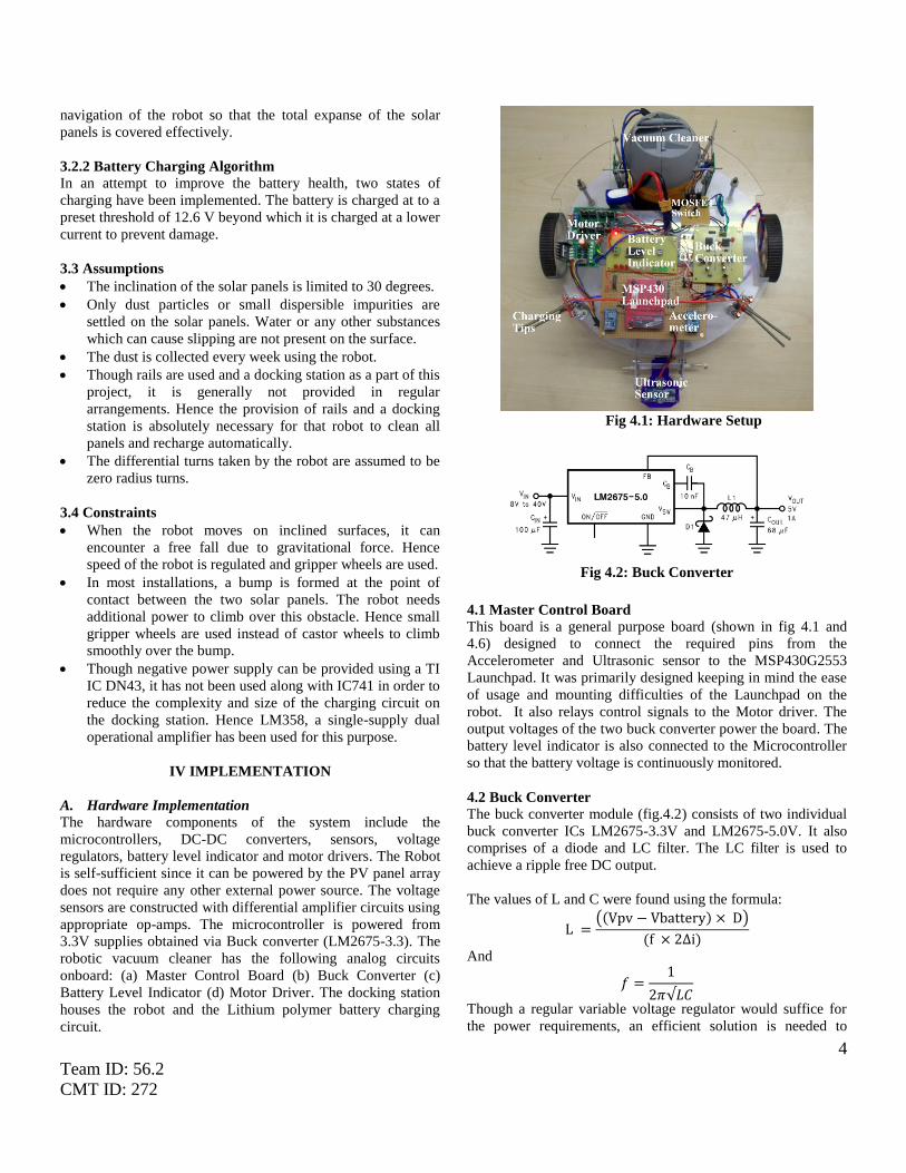
Fig 4.2: Buck Converter
4.1 Master Control Board
This board is a general purpose board (shown in fig 4.1 and
4.6) designed to connect the required pins from the
Accelerometer and Ultrasonic sensor to the MSP430G2553
Launchpad. It was primarily designed keeping in mind the ease
of usage and mounting difficulties of the Launchpad on the
robot. It also relays control signals to the Motor driver. The
output voltages of the two buck converter power the board. The
battery level indicator is also connected to the Microcontroller
so that the battery voltage is continuously monitored.
4.2 Buck Converter The buck converter module (fig.4.2) consists of two individual
buck converter ICs LM2675-3.3V and LM2675-5.0V. It also
comprises of a diode and LC filter. The LC filter is used to
achieve a ripple free DC output.
The values of L and C were found using the formula:
(( ) )
( )
And
Though a regular variable voltage regulator would suffice for
the power requirements, an efficient solution is needed to
5
Team ID: 56.2
CMT ID: 272
guarantee a longer battery life. The vacuum cleaner alone
draws a lot of power. Added to this power is required for
running three other motors and overcome the forces of gravity
and friction. Hence an energy efficient alternative is required.
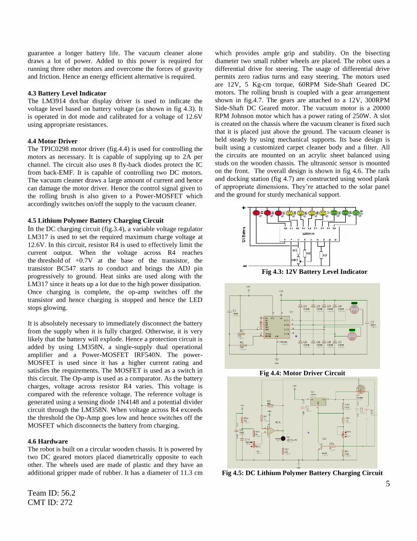
4.3 Battery Level Indicator
The LM3914 dot/bar display driver is used to indicate the
voltage level based on battery voltage (as shown in fig 4.3). It
is operated in dot mode and calibrated for a voltage of 12.6V
using appropriate resistances.
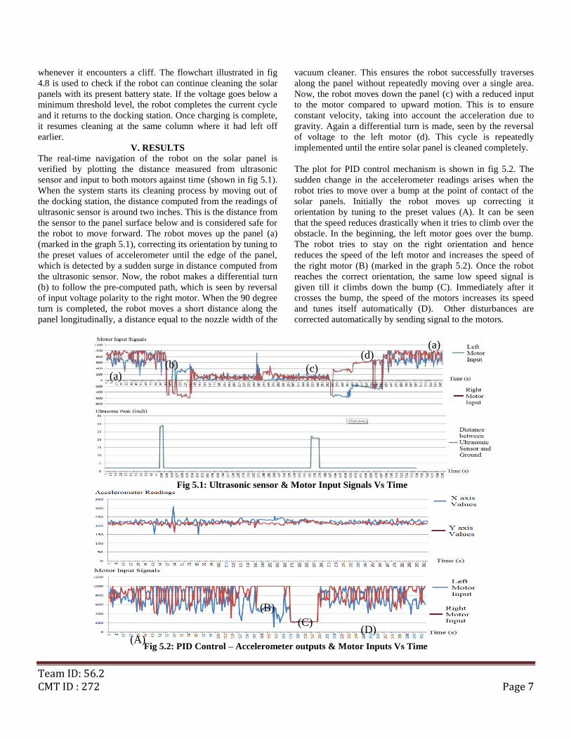
4.4 Motor Driver
The TPIC0298 motor driver (fig.4.4) is used for controlling the
motors as necessary. It is capable of supplying up to 2A per
channel. The circuit also uses 8 fly-back diodes protect the IC
from back-EMF. It is capable of controlling two DC motors.
The vacuum cleaner draws a large amount of current and hence
can damage the motor driver. Hence the control signal given to
the rolling brush is also given to a Power-MOSFET which
accordingly switches on/off the supply to the vacuum cleaner.
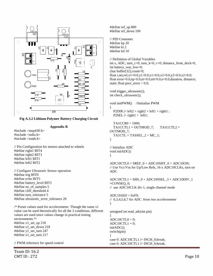
4.5 Lithium Polymer Battery Charging Circuit
In the DC charging circuit (fig.3.4), a variable voltage regulator
LM317 is used to set the required maximum charge voltage at
12.6V. In this circuit, resistor R4 is used to effectively limit the
current output. When the voltage across R4 reaches
the threshold of +0.7V at the base of the transistor, the
transistor BC547 starts to conduct and brings the ADJ pin
progressively to ground. Heat sinks are used along with the
LM317 since it heats up a lot due to the high power dissipation.
Once charging is complete, the op-amp switches off the
transistor and hence charging is stopped and hence the LED
stops glowing.
It is absolutely necessary to immediately disconnect the battery
from the supply when it is fully charged. Otherwise, it is very
likely that the battery will explode. Hence a protection circuit is
added by using LM358N, a single-supply dual operational
amplifier and a Power-MOSFET IRF540N. The power-
MOSFET is used since it has a higher current rating and
satisfies the requirements. The MOSFET is used as a switch in
this circuit. The Op-amp is used as a comparator. As the battery
charges, voltage across resistor R4 varies. This voltage is
compared with the reference voltage. The reference voltage is
generated using a sensing diode 1N4148 and a potential divider
circuit through the LM358N. When voltage across R4 exceeds
the threshold the Op-Amp goes low and hence switches off the
MOSFET which disconnects the battery from charging.
4.6 Hardware
The robot is built on a circular wooden chassis. It is powered by
two DC geared motors placed diametrically opposite to each
other. The wheels used are made of plastic and they have an
additional gripper made of rubber. It has a diameter of 11.3 cm
which provides ample grip and stability. On the bisecting
diameter two small rubber wheels are placed. The robot uses a
differential drive for steering. The usage of differential drive
permits zero radius turns and easy steering. The motors used
are 12V, 5 Kg-cm torque, 60RPM Side-Shaft Geared DC
motors. The rolling brush is coupled with a gear arrangement
shown in fig.4.7. The gears are attached to a 12V, 300RPM
Side-Shaft DC Geared motor. The vacuum motor is a 20000
RPM Johnson motor which has a power rating of 250W. A slot
is created on the chassis where the vacuum cleaner is fixed such
that it is placed just above the ground. The vacuum cleaner is
held steady by using mechanical supports. Its base design is
built using a customized carpet cleaner body and a filter. All
the circuits are mounted on an acrylic sheet balanced using
studs on the wooden chassis. The ultrasonic sensor is mounted
on the front. The overall design is shown in fig 4.6. The rails
and docking station (fig 4.7) are constructed using wood plank
of appropriate dimensions. They‟re attached to the solar panel
and the ground for sturdy mechanical support.
Fig 4.3: 12V Battery Level Indicator
Fig 4.4: Motor Driver Circuit
Fig 4.5: DC Lithium Polymer Battery Charging Circuit

6
Team ID: 56.2
CMT ID: 272
Fig 4.6: Overall Circuit Diagram
Fig 4.7: (i) Robotic Vacuum Cleaner (ii) Docking Station (iii) Connecting Rails
Fig 4.8: Battery Charging Algorithm
B. Software Implementation
The complete algorithm for path-planning, PID control and
battery charging is implemented using the MSP430G2553
microcontroller. The code was primarily tested using Code
Composer Studio which interfaces the microcontroller using the
JTAG interface. The data from various sensors were analyzed
by sending their output data to the Computer using UART
serial communication. The overall path planning algorithm is
implemented as shown in fig 4.9. It uses ADC inputs from
accelerometer and compares it with a preset value. This is to
ensure that the robot exhibits linear motion.
Fig 4.9: Path Planning Algorithm
The MSP430 triggers the ultrasonic sensor periodically and
continuously calculates the distance between the robot and the
ground using the echo pulses. This distance is also compared to
a threshold which enables the robot to act accordingly
Team ID: 56.2 CMT ID : 272 Page 7
whenever it encounters a cliff. The flowchart illustrated in fig
4.8 is used to check if the robot can continue cleaning the solar
panels with its present battery state. If the voltage goes below a
minimum threshold level, the robot completes the current cycle
and it returns to the docking station. Once charging is complete,
it resumes cleaning at the same column where it had left off
earlier.
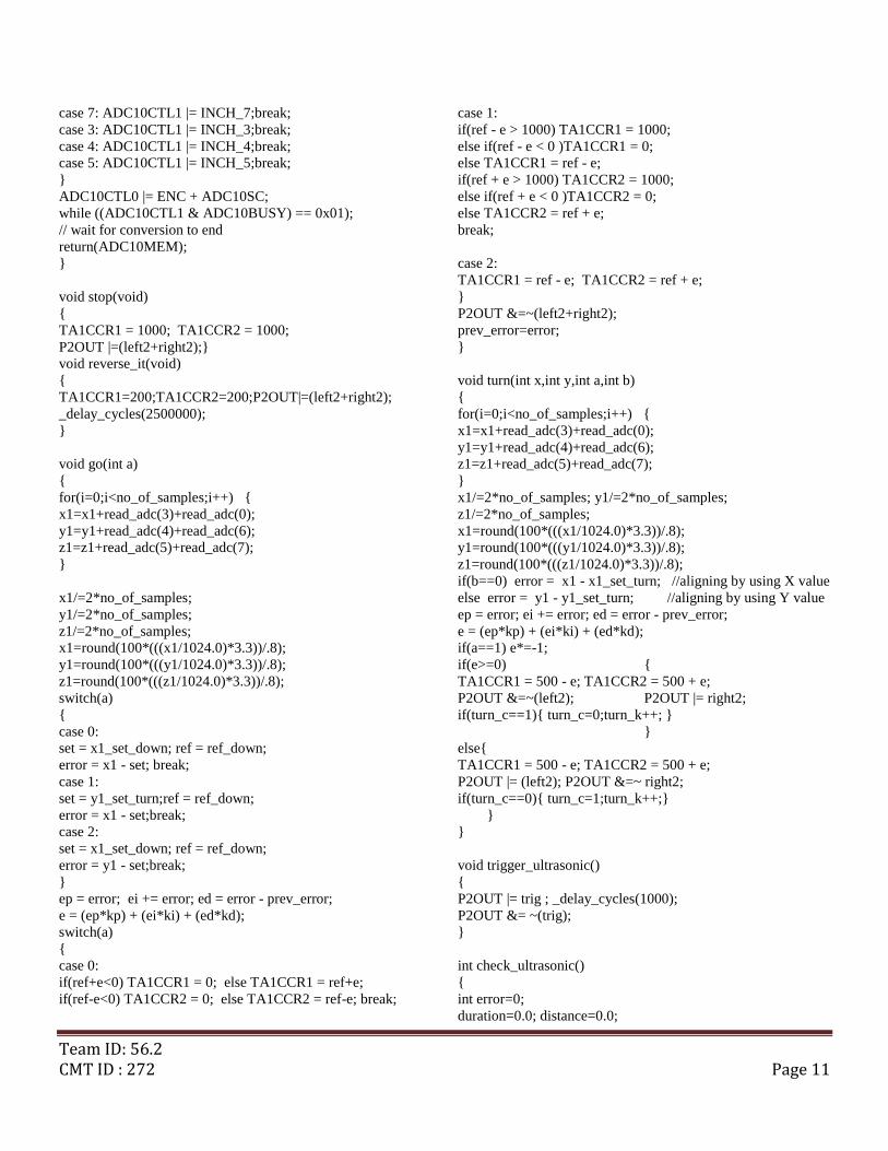
V. RESULTS
The real-time navigation of the robot on the solar panel is
verified by plotting the distance measured from ultrasonic
sensor and input to both motors against time (shown in fig 5.1).
When the system starts its cleaning process by moving out of
the docking station, the distance computed from the readings of
ultrasonic sensor is around two inches. This is the distance from
the sensor to the panel surface below and is considered safe for
the robot to move forward. The robot moves up the panel (a)
(marked in the graph 5.1), correcting its orientation by tuning to
the preset values of accelerometer until the edge of the panel,
which is detected by a sudden surge in distance computed from
the ultrasonic sensor. Now, the robot makes a differential turn
(b) to follow the pre-computed path, which is seen by reversal
of input voltage polarity to the right motor. When the 90 degree
turn is completed, the robot moves a short distance along the
panel longitudinally, a distance equal to the nozzle width of the
vacuum cleaner. This ensures the robot successfully traverses
along the panel without repeatedly moving over a single area.
Now, the robot moves down the panel (c) with a reduced input
to the motor compared to upward motion. This is to ensure
constant velocity, taking into account the acceleration due to
gravity. Again a differential turn is made, seen by the reversal
of voltage to the left motor (d). This cycle is repeatedly
implemented until the entire solar panel is cleaned completely.
The plot for PID control mechanism is shown in fig 5.2. The
sudden change in the accelerometer readings arises when the
robot tries to move over a bump at the point of contact of the
solar panels. Initially the robot moves up correcting it
orientation by tuning to the preset values (A). It can be seen
that the speed reduces drastically when it tries to climb over the
obstacle. In the beginning, the left motor goes over the bump.
The robot tries to stay on the right orientation and hence
reduces the speed of the left motor and increases the speed of
the right motor (B) (marked in the graph 5.2). Once the robot
reaches the correct orientation, the same low speed signal is
given till it climbs down the bump (C). Immediately after it
crosses the bump, the speed of the motors increases its speed
and tunes itself automatically (D). Other disturbances are
corrected automatically by sending signal to the motors.
Fig 5.1: Ultrasonic sensor & Motor Input Signals Vs Time
Fig 5.2: PID Control – Accelerometer outputs & Motor Inputs Vs Time
(a) (b) (c)
(d) (a)
(A)
(B)
(C) (D)

Team ID: 56.2 CMT ID : 272 Page 8
The fig 5.3 shows the result of the cleaning mechanism. The fig
5.4 shows the result of cleaning only once by using the robot to
clean only the solar panel located in the Centre.
Fig 5.3: Cleaning Process
If the robot battery voltage falls below a particular threshold,
The complete cleaning mechanism is shown in [12]. The
overall working principle and circuit design are demonstrated
in [12].
VI. CONCLUSIONS A control strategy for the Robotic Vacuum Cleaner has been
designed and tested. The two stage cleaning mechanism is very
effective in removing dust settled for a long time on solar
panels. Cleaning two to three times instead of just once shows
an improved performance in terms of effectiveness of cleaning.
It has been proved experimentally that the robot can traverse on
inclined surfaces without any difficulty. The robot traverses
entire arrays of the solar panels interconnected using rails
completely and clean with satisfactory results. It travels at a
speed of „2-6‟ cm per second based on the inclination of the
solar panel. If battery level falls below a threshold, it is
confirmed that the robot returns to the docking station and
charges itself automatically. It is verified that the robot returns
to the panel where it stopped cleaning and hence continues with
the cleaning process.
The PV power can be effectively used for charging the battery.
The system can be readily installed for solar panels without any
major modifications in the arrangement. The system is flexible
and can be easily extended to meet the cleaning requirements of
an entire solar farm. Further optimizations in size and cost can
be achieved by using smaller circuit boards and building a
smaller robot.
Using more powerful batteries, vacuum motors and gripper
wheels would be helpful in implementing the robot on a larger
scale. This work can be extended by implementing dust sensing
methods to control the speed of the rolling brush and the
vacuum motor. This system is very helpful to check if an area is
cleaned thoroughly. If the robot is unable to clean a spot it can
be programmed to send a message to the user so that the
particular spot can be cleansed manually to avoid formation of
hotspots. Addition of a gyroscope to the navigation control of
this system would improve the feedback mechanism.
Implementing machine learning concepts would enable the
robot to find preset values by itself accurately, thus making it
fully autonomous and a step closer to be released as a
commercial product.
REFERENCES 1. ABPS Infrastructure Advisory Private Limited, “Development of
Conceptual Framework For Renewable Energy Certificate Mechanism for
India”, Ministry of New and Renewable Energy, June 2009 2. Energy Sector Management Assistance Program (ESMAP) “Paving the
Way for a Transformational Future Lessons from Jawaharlal Nehru
National Solar Mission Phase I”, World Bank, Dec 2013 3. Shaharin A. Sulaiman, Haizatul H. Hussain, Nik Siti H. Nik Leh, and
Mohd S. I. Razali, “Effects of Dust on the Performance of PV Panels”,
World Academy of Science, Engineering and Technology 58 2011
4. J. Zorrilla-Casanova, M. Piliougine, J. Carretero, P. Bernaola, P.Carpena,
L. Mora-López, M. Sidrach-de-Cardona, “Analysis of dust losses in
photovoltaic modules”, World Renewable Energy Congress 2011 – Sweden, 8-13 May 2011, Linkoping, Sweden
5. Theodore G. Stern and Duane Krumweide, Composite Optics, Inc., San
Diego, CA 92121 , “Development of an electrostatically clean solar array panel”, Edward Gaddy, NASA/Goddard Space Flight Center, Greenbelt,
MD, Ira Katz, Maxwell Technologies, Inc., San Diego, CA 92138
6. Rajiv Kohli, Kashmiri L. Mittal, “Developments in Surface Contamination and Cleaning: Methods for Removal of Particle
Contaminants” William Andrew, Elsevier, Volume Three
7. Solar edge “Bypass Diode Effects in Shaded Conditions”, Technical Note 8/2010
8. Ben Tribelhorn and Zachary Dodds, “Evaluating the Roomba: A low-cost,
ubiquitous platform for robotics research and education”, Robotics and Automation, 2007 IEEE International Conference on, pp 1393 – 1399,
10-14 April 2007
9. Tod E. Kurt, “Hacking Roomba”, Wiley Publishing Inc, Extreme Tech 10. Jodi Forlizzi, Carl DiSalvo, Carnegie Mellon University, “Service Robots
in the Domestic Environment: A Study of the Roomba Vacuum in the
Home”, HRI‟06 Proceedings of the 1st ACM SIGCHI/SIGART conference on Human-robot interaction, ACM pp 258-265, 2006
11. Sellers, David. "An Overview of Proportional plus Integral plus
Derivative Control and Suggestions for Its Successful Application and
Implementation" (PDF). Archived from the original on March 7,
2007. Retrieved 2007-05-05.
12. Project Demonstration:
http://www.youtube.com/watch?v=qiCRSVuftFQ

Team ID: 56.2 CMT ID : 272 Page 9
Appendix A
PCB Designs
Fig A.1.1: Battery Level Indicator
Fig A.1.2: Battery Level Indicator
Fig A.2.1: DC-DC Buck Converter
Fig A.2.2: DC-DC Buck Converter
Fig A.3.1: Lithium Polymer Battery Charging Circuit
Team ID: 56.2 CMT ID : 272 Page 10
Fig A.3.2 Lithium Polymer Battery Charging Circuit
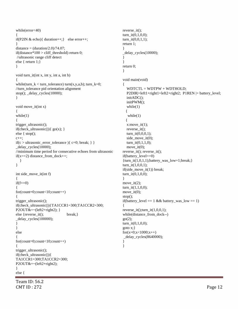
Appendix B
#include <msp430.h>
#include <stdio.h>
#include <math.h>
// Pin Configuration for motors attached to wheels
#define right1 BIT4
#define right2 BIT3
#define left1 BIT1
#define left2 BIT2
// Configure Ultrasonic Sensor operation
#define trig BIT0
#define echo BIT5
#define battery_level BIT1
#define no_of_samples 5
#define cliff_threshold 4
#define turn_tolerance 5
#define ultrasonic_error_tolerance 20
/* Preset values used for accelerometer. Though the same x1
value can be used theoretically for all the 3 conditions, different
values are used since values change in practical testing
environments */
#define x1_set_up 218
#define x1_set_down 218
#define y1_set_turn 247
#define x1_set_turn 217
// PWM reference for speed control
#define ref_up 800
#define ref_down 100
// PID Constants
#define kp 20
#define ki 2
#define kd 10
// Definition of Global Variables
int x, ADC, turn_c=0, turn_k=0, c=0; distance_from_dock=0,
int battery_was_low=0;
char buffer[32],count=0;
float i,set,ref,x1=0.0,y1=0.0,z1=0.0,x2=0.0,y2=0.0,z2=0.0;
float error=0.0,ep=0.0,ei=0.0,ed=0.0,e=0.0,duration, distance;
static float prev_error = 0.0;
void trigger_ultrasonic();
int check_ultrasonic();
void initPWM() //Initialize PWM
{
P2DIR |= left2 + right2 + left1 + right1 ;
P2SEL |= right1 + left1;
TA1CCR0 = 1000;
TA1CCTL1 = OUTMOD_7; TA1CCTL2 =
OUTMOD_7;
TA1CTL = TASSEL_2 + MC_1;
}
// Initialize ADC
void initADC()
{
ADC10CTL0 = SREF_0 + ADC10SHT_0 + ADC10ON;
// Use Vcc/Vss for Up/Low Refs, 16 x ADC10CLKs, turn on
ADC
ADC10CTL1 = SHS_0 + ADC10SSEL_3 + ADC10DIV_1
+CONSEQ_0;
// use ADC10CLK div 1, single channel mode
ADC10AE0 = 0xF9;
// 0,3,4,5,6,7 for ADC from two accelerometer
}
unsigned int read_adc(int pin)
{
ADC10CTL0 = 0;
ADC10CTL1 = 0;
initADC();
switch(pin)
{
case 0: ADC10CTL1 |= INCH_0;break;
case 6: ADC10CTL1 |= INCH_6;break;
Team ID: 56.2 CMT ID : 272 Page 11
case 7: ADC10CTL1 |= INCH_7;break;
case 3: ADC10CTL1 |= INCH_3;break;
case 4: ADC10CTL1 |= INCH_4;break;
case 5: ADC10CTL1 |= INCH_5;break;
}
ADC10CTL0 |= ENC + ADC10SC;
while ((ADC10CTL1 & ADC10BUSY) == 0x01);
// wait for conversion to end
return(ADC10MEM);
}
void stop(void)
{
TA1CCR1 = 1000; TA1CCR2 = 1000;
P2OUT |=(left2+right2);}
void reverse_it(void)
{
TA1CCR1=200;TA1CCR2=200;P2OUT|=(left2+right2);
_delay_cycles(2500000);
}
void go(int a)
{
for(i=0;i<no_of_samples;i++) {
x1=x1+read_adc(3)+read_adc(0);
y1=y1+read_adc(4)+read_adc(6);
z1=z1+read_adc(5)+read_adc(7);
}
x1/=2*no_of_samples;
y1/=2*no_of_samples;
z1/=2*no_of_samples;
x1=round(100*(((x1/1024.0)*3.3))/.8);
y1=round(100*(((y1/1024.0)*3.3))/.8);
z1=round(100*(((z1/1024.0)*3.3))/.8);
switch(a)
{
case 0:
set = x1_set_down; ref = ref_down;
error = x1 - set; break;
case 1:
set = y1_set_turn;ref = ref_down;
error = x1 - set;break;
case 2:
set = x1_set_down; ref = ref_down;
error = y1 - set;break;
}
ep = error; ei += error; ed = error - prev_error;
e = (ep*kp) + (ei*ki) + (ed*kd);
switch(a)
{
case 0:
if(ref+e<0) TA1CCR1 = 0; else TA1CCR1 = ref+e;
if(ref-e<0) TA1CCR2 = 0; else TA1CCR2 = ref-e; break;
case 1:
if(ref - e > 1000) TA1CCR1 = 1000;
else if(ref - e < 0 )TA1CCR1 = 0;
else TA1CCR1 = ref - e;
if(ref + e > 1000) TA1CCR2 = 1000;
else if(ref + e < 0 )TA1CCR2 = 0;
else TA1CCR2 = ref + e;
break;
case 2:
TA1CCR1 = ref - e; TA1CCR2 = ref + e;
}
P2OUT &=~(left2+right2);
prev_error=error;
}
void turn(int x,int y,int a,int b)
{
for(i=0;i<no_of_samples;i++) {
x1=x1+read_adc(3)+read_adc(0);
y1=y1+read_adc(4)+read_adc(6);
z1=z1+read_adc(5)+read_adc(7);
}
x1/=2*no_of_samples; y1/=2*no_of_samples;
z1/=2*no_of_samples;
x1=round(100*(((x1/1024.0)*3.3))/.8);
y1=round(100*(((y1/1024.0)*3.3))/.8);
z1=round(100*(((z1/1024.0)*3.3))/.8);
if(b==0) error = x1 - x1_set_turn; //aligning by using X value
else error = y1 - y1_set_turn; //aligning by using Y value
ep = error; ei += error; ed = error - prev_error;
e = (ep*kp) + (ei*ki) + (ed*kd);
if(a==1) e*=-1;
if(e>=0) {
TA1CCR1 = 500 - e; TA1CCR2 = 500 + e;
P2OUT &=~(left2); P2OUT |= right2;
if(turn_c==1){ turn_c=0;turn_k++; }
}
else{
TA1CCR1 = 500 - e; TA1CCR2 = 500 + e;
P2OUT |= (left2); P2OUT &=~ right2;
if(turn_c==0){ turn_c=1;turn_k++;}
}
}
void trigger_ultrasonic()
{
P2OUT |= trig ; _delay_cycles(1000);
P2OUT &= ~(trig);
}
int check_ultrasonic()
{
int error=0;
duration=0.0; distance=0.0;
Team ID: 56.2 CMT ID : 272 Page 12
while(error<40)
{
if(P2IN & echo){ duration++;} else error++;
}
distance = (duration/2.0)/74.07;
if(distance*100 > cliff_threshold) return 0;
//ultrasonic range cliff detect
else { return 1;}
}
void turn_it(int x, int y, int a, int b)
{
while(turn_k < turn_tolerance) turn(x,y,a,b); turn_k=0;
//turn_tolerance pid orientation alignment
stop(); _delay_cycles(10000);
}
void move_it(int x)
{
while(1)
{
trigger_ultrasonic();
if(check_ultrasonic()){ go(x); }
else { stop();
c++;
if(c > ultrasonic_error_tolerance ){ c=0; break; } }
_delay_cycles(10000);
//minimum time period for consecutive echoes from ultrasonic
if(x==2) distance_from_dock++;
}
}
int side_move_it(int f)
{
if(f==0)
{
for(count=0;count<10;count++)
{
trigger_ultrasonic();
if(check_ultrasonic()){TA1CCR1=300;TA1CCR2=300;
P2OUT&=~(left2+right2); }
else {reverse_it(); break;}
_delay_cycles(100000);
}
}
else
{
for(count=0;count<10;count++)
{
trigger_ultrasonic();
if(check_ultrasonic()){
TA1CCR1=300;TA1CCR2=300;
P2OUT&=~(left2+right2);
}
else {
reverse_it();
turn_it(0,1,0,0);
turn_it(0,0,1,1);
return 1;
}
_delay_cycles(10000);
}
}
return 0;
}
void main(void)
{
WDTCTL = WDTPW + WDTHOLD;
P2DIR|=left1+right1+left2+right2; P1REN |= battery_level;
initADC();
initPWM();
while(1)
{
while(1)
{
x:move_it(1);
reverse_it();
turn_it(0,0,0,1);
side_move_it(0);
turn_it(0,1,1,0);
move_it(0);
reverse_it(); reverse_it();
if(battery_level==0)
{turn_it(1,0,1,1);battery_was_low=1;break;}
turn_it(1,0,0,1);
if(side_move_it(1)) break;
turn_it(0,1,0,0);
}
move_it(2);
turn_it(1,1,0,0);
move_it(0);
stop();
if(battery_level == 1 && battery_was_low == 1)
{
reverse_it();turn_it(1,0,0,1);
while(distance_from_dock--)
go(2);
turn_it(0,1,0,0);
goto x;}
for(x=0;x<1000;x++)
_delay_cycles(8640000);
}
}
Team ID: 56.2 CMT ID : 272 Page 13
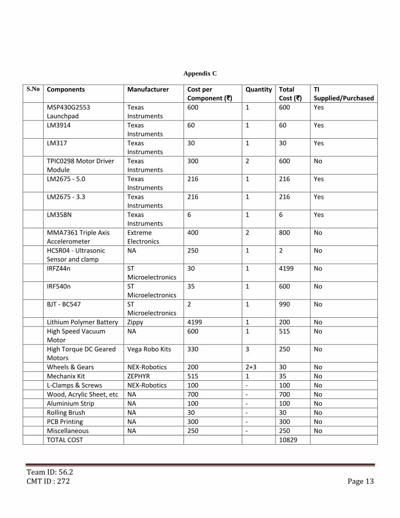
Appendix C
S.No Components Manufacturer Cost per Component (₹)
Quantity Total Cost (₹)
TI Supplied/Purchased
MSP430G2553 Launchpad
Texas Instruments
600 1 600 Yes
LM3914 Texas Instruments
60 1 60 Yes
LM317 Texas Instruments
30 1 30 Yes
TPIC0298 Motor Driver Module
Texas Instruments
300 2 600 No
LM2675 - 5.0 Texas Instruments
216 1 216 Yes
LM2675 - 3.3 Texas Instruments
216 1 216 Yes
LM358N Texas Instruments
6 1 6 Yes
MMA7361 Triple Axis Accelerometer
Extreme Electronics
400 2 800 No
HCSR04 - Ultrasonic Sensor and clamp
NA 250 1 2 No
IRFZ44n ST Microelectronics
30 1 4199 No
IRF540n ST Microelectronics
35 1 600 No
BJT - BC547 ST Microelectronics
2 1 990 No
Lithium Polymer Battery Zippy 4199 1 200 No
High Speed Vacuum Motor
NA 600 1 515 No
High Torque DC Geared Motors
Vega Robo Kits 330 3 250 No
Wheels & Gears NEX-Robotics 200 2+3 30 No
Mechanix Kit ZEPHYR 515 1 35 No
L-Clamps & Screws NEX-Robotics 100 - 100 No
Wood, Acrylic Sheet, etc NA 700 - 700 No
Aluminium Strip NA 100 - 100 No
Rolling Brush NA 30 - 30 No
PCB Printing NA 300 - 300 No
Miscellaneous NA 250 - 250 No
TOTAL COST 10829