Embed Size (px)
Citation preview
Cite this article: Welzbacher, P., Vorwerk-Handing, G., Kirchner, E. (2021) ‘A Control List for the Systematic Identification of Disturbance Factors’, in Proceedings of the International Conference on Engineering Design (ICED21), Gothenburg, Sweden, 16-20 August 2021. DOI:10.1017/pds.2021.6
ICED21 51
INTERNATIONAL CONFERENCE ON ENGINEERING DESIGN, ICED21 16-20 AUGUST 2021, GOTHENBURG, SWEDEN
ICED21 1
A CONTROL LIST FOR THE SYSTEMATIC IDENTIFICATION OF DISTURBANCE FACTORS Welzbacher, Peter; Vorwerk-Handing, Gunnar; Kirchner, Eckhard Technical University of Darmstadt; Institute for Product Development and Machine Elements (pmd)
ABSTRACT The importance of considering disturbance factors in the product development process is often emphasized as one of the key factors to a functional and secure product. However, there is only a small number of tools to support the developer in the identification of disturbance factors and none of them yet ensures that the majority of occurring disturbance factors is considered. Thus, it is the aim of this contribution to provide a tool in form of a control list for the systematic identification of disturbance factors. At the beginning of this contribution, the terms “disturbance factor” and “uncertainty” are defined based on a literature review and different approaches for the classification of uncertainty are presented. Subsequently, the fundamentals of multipole based model theory are outlined. Moreover, a first approach in terms of a control list for a systematic identification of disturbance factors is discussed. Based on the discussed approach and taking the identified weaknesses as a starting point, a control list is presented that combines the existing basic concept of the control list with the fundamentals of multipole based model theory. Keywords: Design methods, Uncertainty, Early design phases, Disturbance factor Contact: Welzbacher, Peter Technical University Darmstadt Institute for Product Development and Machine Elements (pmd) Germany [email protected]

52 ICED21
1 INTRODUCTION AND MOTIVATION
Considering disturbance factors in the framework of the product development process is often
emphasized as key to a functional, secure and stable product. For example, Pahl et al. (2007) state that
“disturbance factors such as temperature, humidity, dust, vibrations etc. can cause effects that should not
be neglected” (Pahl et al., 2007, p. 521). Thus, it is crucial for the success of the later product to identify
and consider these disturbance factors as well as their effects on the functionality of the product with
regard to robust design as early as possible in the product development process respectively already in
the early phase of concept development (cf. Pahl et al., 2007; Taguchi et al., 2005)
For the identification and evaluation of possible negative effects of disturbance factors in terms of
failures, a variety of standardised methods can be used, for example, the failure tree analysis (FTA),
failure mode and effects analysis (FMEA) or hazard and operability analysis (HAZOP). Moreover,
effect catalogues, for example, the one proposed by Koller (1998) can be used to systematically
identify possible physical effects that are caused by disturbance factors and may influence the
functionality of the product negatively (cf. Vorwerk-Handing et al., 2020). However, all these
methods and approaches have in common that they do not include or refer to a systematic approach or
tool to support the developer in the systematic identification of occurring disturbance factors.
Thus, it cannot be ensured that the majority of occurring disturbance factors that may result in function-
critical effects is identified. This results in a remaining uncertainty regarding the functionality of the
product to be developed under real conditions of use. This problem is also often addressed in the context
of uncertainty management, for example, in the Variation Mode and Effects Analysis by Chakhunashvili
et al. (2004). Oftentimes, it is simply assumed that the developer has already enough knowledge and/or
experience to be able to identify all relevant disturbance factors (cf. Pahl et al., 2007).
Especially in terms of industry 4.0 the identification and consideration of disturbance factors is of
great importance to ensure the functionality of measuring functions to be integrated into technical
systems as a first step towards cyber-physical systems (cf. Vorwerk-Handing et al., 2018). Due to the
above-mentioned lack of support of the developer in the identification of disturbance factors, there is
always uncertainty remaining regarding the functionality and robustness of these functions.
The aim of this contribution is therefore to provide a suitable tool in the form of a control list to support
the developer as early as possible in the identification of occurring disturbance factors and consequently
create a basis for the subsequent systematic identification and consideration of the caused effects.
2 FUNDAMENTALS AND STATE OF RESEARCH
This section begins with defining the terms “disturbance factor” and “uncertainty” based on a literature
review to ensure a uniform understanding of these terms for the following part of this contribution.
Furthermore, different existing approaches for the classification of uncertainty are portrayed. Subsequently,
as basis for the later on presented control list, the fundamentals of multipole based model theory are
described and a first approach in terms of a control list for the systematic identification of disturbance
factors is presented and discussed.
2.1 Definition of disturbance factor
In control engineering, a disturbance factor, also referred to as disturbance variable, is described as an
unwanted, independent and often unpredictable input quantity of a technical system that arises from
the systems surrounding (cf. Heinrich and Schneider, 2019). The overall goal in control engineering is
to eliminate or at least minimise the impact of these factors on the system in order to be able to fulfil
an intended function without the occurrence of errors and/or failures and ensure the systems stability
(cf. Feldhusen and Grote, 2013).
In robust design the overall goal is to design a system that is insensitive, i.e. robust, and thus will be
least affected by “noise factors” (cf. Taguchi et al., 2005; Andersson, 1997). In this context, Taguchi
et al. (2005) define “noise factor” as any uncontrollable factor that causes a variation in product
quality. Furthermore, three basic types of noise are distinct:
– noise due to external causes (for example temperature or vibration),
– noise due to internal causes (for example wear or material conversion) and
– noise due to part-to-part or product-to-product variation (for example production imprecisions).

ICED21 53
According to Taguchi et al. (2005), disturbance factors, as described in the context of control
engineering, are a subtype of noise factors and are referred to, in the context of robust design, as noise
due to external causes.
Both described views have in common, that a disturbance factor or noise due to external causes is seen
as an unwanted input originating from the surrounding and influences the behaviour of the system in a
negative way. This common understanding of a disturbance factor is used in the following.
2.2 Definition of uncertainty
Uncertainty is a term that is used in many scientific disciplines with different understandings (cf.
Hanselka and Platz, 2010). Thus, it is not possible to define this term in a way to fit all the different
understandings. As a consequence, the following definition and explanation of the term “uncertainty”
is referring exclusively to the understanding of uncertainty in product development.
Galbraith (1973) describes uncertainty in terms of a task as “the difference between the amount of
information required to perform the task and the amount of information already possessed” (Galbraith,
1973, p. 5). This understanding of uncertainty as a lack of information is taken up in a more general
way in the ISO Guide 73 (2009) in which uncertainty is defined as “state, even partial, of deficiency of
information related to, understanding or knowledge of, an event, its consequence, or likelihood”
(International Organization for Standardization, 2009, p. 2). In the further course of this contribution,
the definition from the ISO Guide 73 (2009) is used.
2.3 Approaches for classification of uncertainty
In literature, uncertainty is often distinct based on:
– its manifestation,
– its level and/or
– its nature.
The categorisation of uncertainty according to its manifestation refers to the location in a system
model where uncertainty occurs. A distinction is made between “context uncertainty”, “model
uncertainty”, “data uncertainty” and “phenomenological uncertainty” (cf. Kreye et al., 2011). The
different manifestations of uncertainty are shown in Figure 1 in a system model.
Figure 1: Manifestation of uncertainty in a system model (Kreye et al., 2011)
The context of a system describes the circumstances and conditions that surround the technical system
under consideration. Hence, context uncertainty describes the potential deficiency from influence of
the context on the considered system. Data uncertainty, also referred to as input uncertainty, is the
uncertainty that is connected to the input of a system or its model. However, input does not only
include the actual input of the system or its model but also its design parameters. Uncertainty that
results from modelling inaccuracies, made consciously or unconsciously, for example, in terms of
simplified relations used in the system model, are designated as model uncertainty. Model uncertainty
may result in a discrepancy between the predicted and the real system behaviour. The last type of
manifestation of uncertainty is phenomenological uncertainty. Phenomenological uncertainty refers to
the unpredictability of the future that is caused by unknown events or influences. It is, per definition,
impossible to fully know or model this manifestation because there may always be the influence of an
unexpected, and thus neglected, event. (cf. Walker et al., 2003; Kreye et al., 2011)

54 ICED21
The level of uncertainty refers to the amount of available and/or reliable information about an uncertainty
affected quantity, for example, a design parameter. According to Walker et al. (2003), the spectrum
ranges from “total ignorance” up to “determinism”. This idea for a classification of uncertainty was
taken up by the Collaborative Research Centre (CRC) 805, refined in terms of the definition of the
individual levels and extended regarding the knowledge about the effect of uncertainty. The uncertainty
model of the CRC 805 is shown in Figure 2. At this point it must be noted that determinacy is an
unattainable ideal in reality. (cf. Walker et al., 2003; Lotz, 2018; based on Engelhardt et al., 2010)
Figure 2: Uncertainty model of the CRC 805 (following Lotz, 2018)
In contrast to that, the nature of uncertainty describes the kind of relationship between uncertainty and
information. Two types of uncertainty are distinct: epistemic and aleatory uncertainty. Epistemic
uncertainty is uncertainty that results from a lack of information and thus can be reduced by gaining
more information (cf. Oberkampf et al., 2002; Walker et al., 2003). Due to that, epistemic uncertainty
is also often referred to as reducible uncertainty. In contrast to that, aleatory uncertainty cannot be
reduced by gaining more information. It is present under the assumption that the system is fully
describable and complete information exists, which is why it is also called irreducible uncertainty. It is
caused by inherent variation associated with the system under consideration or its environment (cf.
Oberkampf et al., 2002; Walker et al., 2003). The classification of uncertainty according to its nature
is also shown in Figure 2 as bar in the lower part. It has to be noted that the bar represents the relative
share of the individual type of uncertainty and not the absolute.
2.4 Fundamentals of multipole based model theory
The multipole-based model theory is used to create abstract cross-domain models of technical systems
based on elementary principles of conservation of energy using concentrated network elements with
two or more defined pols. The poles act as connectors between the different locally and functionally
delimited network elements from different physical domains and allow them an energy transfer.
Examples of physical domains are mechanics, electricity, hydraulics or thermodynamics. (cf.
Janschek, 2010)
The basic idea of multipole-based model theory is that the energy transfer between different network
elements is characterised by two generalised energy variables: a generalised flow variable f and a
generalised effort variable e (cf. Wellstead, 1979). A generalised flow variable f describes a variable
that travels through a network element and can be measured at a single pole of the element, for
example an electric current I. In contrast to that, a generalised effort variable e can only be measured
between two poles of a network element, for example an electric voltage U. (cf. Janschek, 2010)
The difference between these two variables is illustrated in Figure 3 using a concentrated network
element with two poles.
Aleatory Uncertainty Epistemic Uncertainty
UncertaintyDeterminacy
eff
ect
kn
ow
n
eff
ect
un
kno
wn
exact models,complete
information
determinate variability
known probability
density function (PDF)
estimated PDF or membership function (MF)
unknown or partly unknown PDF, estimated
MF, ranges
known or estimated
uncertainty, intentionally
neglected
model and parameter not
sufficiently known
unknown variability
uncertain variability
Stochastic Uncertainty
Estimated Uncertainty
Estimated Uncertainty
Ignored Uncertainty
Determinacy Nescience

ICED21 55
Figure 3: Concentrated network element with two poles (cf. Janschek, 2010)
The resulting generalised energy E(t) that is transferred between two different network elements over
the period of time t is calculated using equation (1) (cf. Janschek, 2010).
( ) ∫ ( )
∫ ( ) ( )
(1)
Due to the circumstance that there is only a limited number of existing physical domains, there is also
only a limited number of generalised energy variables to describe the energy transfer between different
network elements.
2.5 Previous work
Based on the list of standardised disturbance factors by Mathias (2016), Vorwerk-Handing et al. (2020)
developed a control list to support the developer in the systematic identification of disturbance factors in
the early phase of the product development process. For this purpose, the different standardised
disturbance factors defined by Mathias (2016) were first assigned to their corresponding physical
domains. Subsequently, each standardised disturbance factor, called potential disturbance variable by
Vorwerk-Handing et al. (2020), was linked with its corresponding so-called physical influencing
variables that directly act on, and thus influence, the considered technical system (cf. Vorwerk-Handing
et al., 2020). An extract of the control list by Vorwerk-Handing et al. (2020) is shown in Figure 4.
Figure 4: Extract of the disturbance factor control list (Vorwerk-Handing et al., 2020)
The influencing variables of the occurring potential disturbance variables can be used in a subsequent
step for a systematic identification of potential effects of these disturbance variables on a technical
system to be developed. Therefore, the different influencing variables are considered as inputs of
“unintended” physical effects that may affect the systems functionality or stability in a negative way.
These physical effects are called unintended because they are not intended in terms of the basic
physical concept of the technical system to be developed. For the systematic identification of
unintended physical effects, physical effect catalogues can be used, for example the one proposed by
Koller (1998) or Vorwerk-Handing (2021). A detailed description of the identification process of
unintended physical effects can be found in Vorwerk-Handing et al. (2020) and will not be further
elaborated here as it is not in the focus of this publication. (cf. Vorwerk-Handing et al., 2020)
However, the control list by Vorwerk-Handing et al. (2020) has two major weaknesses. On the one
hand, the control list builds up on the list of standardised disturbance factors by Mathias (2016). The
major problem of this list is that the methodology that was used to identify and define these
standardised disturbance factors is unclear. This results in ambiguities, for example, why there is a
distinction made between heat supply and heat dissipation, although both describe a heat transfer in
general, and which benefits result from this distinction. In addition to that, it stays unclear why the
Concentratednetwork element
f(t)
e(t)
56 ICED21
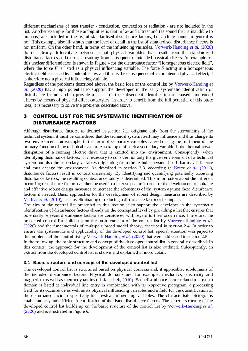
different mechanisms of heat transfer - conduction, convection or radiation - are not included in the
list. Another example for those ambiguities is that infra- and ultrasound (as sound that is inaudible to
humans) are included in the list of standardised disturbance factors, but audible sound in general is
not. This example also illustrates that the level of detail in the list of standardised disturbance factors is
not uniform. On the other hand, in terms of the influencing variables, Vorwerk-Handing et al. (2020)
do not clearly differentiate between actual physical variables that result from the standardised
disturbance factors and the ones resulting from subsequent unintended physical effects. An example for
this unclear differentiation is shown in Figure 4 for the disturbance factor “Homogeneous electric field”,
where the force F is listed as a physical influencing variable. The force F acting in a homogeneous
electric field is caused by Coulomb´s law and thus is the consequence of an unintended physical effect, it
is therefore not a physical influencing variable.
Regardless of the problems described above, the basic idea of the control list by Vorwerk-Handing et
al. (2020) has a high potential to support the developer in the early systematic identification of
disturbance factors and to provide a basis for the subsequent identification of caused unintended
effects by means of physical effect catalogues. In order to benefit from the full potential of this basic
idea, it is necessary to solve the problems described above.
3 CONTROL LIST FOR THE SYSTEMATIC IDENTIFICATION OF
DISTURBANCE FACTORS
Although disturbance factors, as defined in section 2.1, originate only from the surrounding of the
technical system, it must be considered that the technical system itself may influence and thus change its
own environment, for example, in the form of secondary variables caused during the fulfilment of the
primary function of the technical system. An example of such a secondary variable is the thermal power
dissipation of a running electric drive that is emitted into the environment. Consequently, when
identifying disturbance factors, it is necessary to consider not only the given environment of a technical
system but also the secondary variables originating from the technical system itself that may influence
and thus change the environment. As described in section 2.3, according to Kreye et al. (2011),
disturbance factors result in context uncertainty. By identifying and quantifying potentially occurring
disturbance factors, the resulting context uncertainty is determined. This information about the different
occurring disturbance factors can then be used in a later step as reference for the development of suitable
and effective robust design measures to increase the robustness of the system against these disturbance
factors if needed. Basic approaches for the development of robust design measures are described by
Mathias et al. (2010), such as eliminating or reducing a disturbance factor or its impact.
The aim of the control list presented in this section is to support the developer in the systematic
identification of disturbance factors already on the conceptual level by providing a list that ensures that
potentially relevant disturbance factors are considered with regard to their occurrence. Therefore, the
presented control list builds up on the basic concept of the control list by Vorwerk-Handing et al.
(2020) and the fundamentals of multipole based model theory, described in section 2.4. In order to
ensure the systematics and applicability of the developed control list, special attention was payed to
the problems of the control list by Vorwerk-Handing et al. (2020) that were addressed in section 2.5.
In the following, the basic structure and concept of the developed control list is generally described. In
this context, the approach for the development of the control list is also outlined. Subsequently, an
extract from the developed control list is shown and explained in more detail.
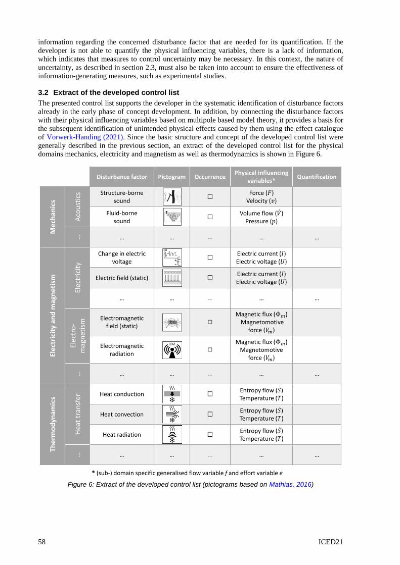
3.1 Basic structure and concept of the developed control list
The developed control list is structured based on physical domains and, if applicable, subdomains of
the included disturbance factors. Physical domains are, for example, mechanics, electricity and
magnetism as well as thermodynamics (cf. Janschek, 2010). Each disturbance factor related to a (sub-)
domain is listed as individual line entry in combination with its respective pictogram, a processing
field for its occurrence as well as its physical influencing variables and a field for the quantification of
the disturbance factor respectively its physical influencing variables. The characteristic pictograms
enable an easy and efficient identification of the listed disturbance factors. The general structure of the
developed control list builds up on the basic structure of the control list by Vorwerk-Handing et al.
(2020) and is illustrated in Figure 6.

ICED21 57
In the course of the identification and definition of disturbance factors to be included in the control
list, the list of standardised disturbance factors from Mathias (2016) was first analysed in detail for
existing ambiguities as well as inconsistencies in its level of detail. Based on this information, the list
of standardised disturbance factors was first reduced by summarizing similar disturbance factors, for
example heat supply and heat dissipation, as well as extended in some points, for example in the field
of nuclear physics, to achieve a uniform level of detail and eliminate ambiguities. In the next step, the
modified list was structured according to the addressed physical (sub-) domain of each disturbance
factor, similar to the control list from Vorwerk-Handing et al. (2020). Subsequently, each disturbance
factor was analysed with the help of guide words, like the ones used in HAZOP to predict
malfunctions or deviations, for example, “more/less”, “invert” or “otherwise” to systematically
generate disturbance factors that were not yet included and thus unconsidered. In order to be able to
control the amount of disturbance factors generated with this divergent approach, the additionally
identified disturbance factors were analysed and compared with the already included disturbance
factors regarding their similarity and if possible combined. Using this convergent approach, on the one
hand, the total number of disturbance factors included in the control list was reduced and, on the other
hand, ambiguities regarding the exact differentiation of similar disturbance variables were avoided. It
must be noted at this point, that in a few cases a disturbance factor is relevant in more than one
physical domain and thus is included more than once in the control list. An example for such a
disturbance factor is γ-radiation which is included in the physical domain “nuclear physics” as well as
in the domain “electricity and magnetism” in the subdomain “electromagnetic radiation”.
Each identified disturbance factor is generally characterised by its physical influencing variables that
directly act on the considered system and may cause unintended physical effects (cf. Vorwerk-
Handing et al., 2020). As described in section 2.4, the energy transfer between two network elements,
in this context between the considered technical system and its environment, is describable using a
generalised flow variable f and a generalised effort variable e. Thus, these two variables are sufficient
to fully describe a disturbance factor. The same applies to the energy transfer from the technical
system to its environment in terms of secondary variables. The interactions between a technical system
and its environment are shown in Figure 5.
Figure 5: Interactions between a technical system and its environment (based on Wellstead, 1979)
The physical effects caused by the physical influencing variables of occurring disturbance factors can be
systematically identified using the effect catalogue of Vorwerk-Handing (2021). This catalogue system is
also based on the principles of multipole based model theory and thus includes the generalised flow and
effort variables of the different physical domains as input and output of known physical effects. The
generalised energy variables of each occurring disturbance factor are considered as input of unintended
physical effects, which can negatively influence the functionality of the technical system. An example
for such a negative influence is the dependence of a functionally relevant input quantity on an acting
physical influencing variables, which results in an impermissible deviation of this quantity.
The last column in the control list is used for the quantification of the corresponding physical
influencing variables of the occurring disturbance factors. By quantifying these variables, the
developer determines the present level of uncertainty, as described in section 2.3, associated with the
individual disturbance factors. Therefore, the developer must check the availability and reliability of
Disturbance factor ( )(describable using a generalised flow variable
and effort variable )
Secondary variable ( )(describable using a generalised flow variable and effort variable )
Environment of the technical system
Technicalsystem
( ) ( )
( )
( )
58 ICED21
information regarding the concerned disturbance factor that are needed for its quantification. If the
developer is not able to quantify the physical influencing variables, there is a lack of information,
which indicates that measures to control uncertainty may be necessary. In this context, the nature of
uncertainty, as described in section 2.3, must also be taken into account to ensure the effectiveness of
information-generating measures, such as experimental studies.
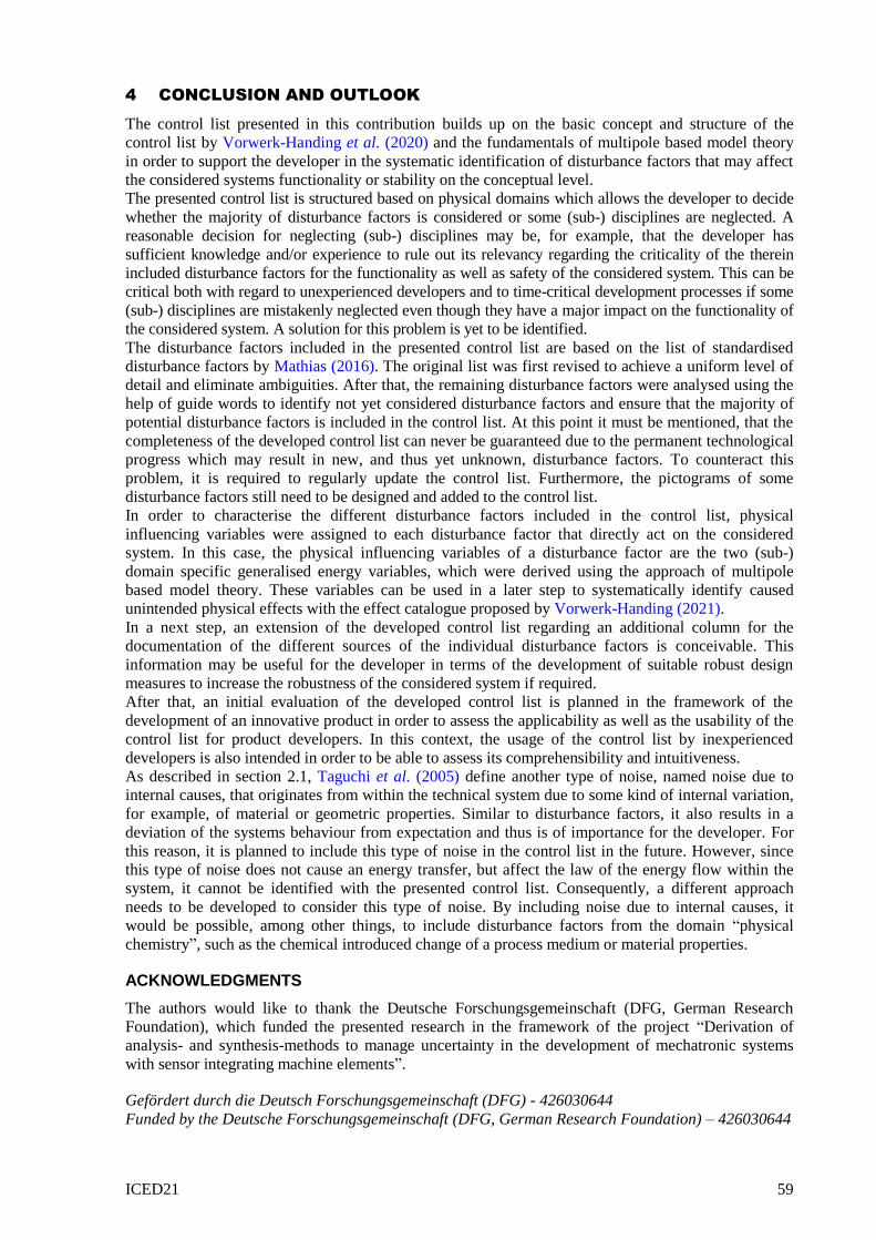
3.2 Extract of the developed control list
The presented control list supports the developer in the systematic identification of disturbance factors
already in the early phase of concept development. In addition, by connecting the disturbance factors
with their physical influencing variables based on multipole based model theory, it provides a basis for
the subsequent identification of unintended physical effects caused by them using the effect catalogue
of Vorwerk-Handing (2021). Since the basic structure and concept of the developed control list were
generally described in the previous section, an extract of the developed control list for the physical
domains mechanics, electricity and magnetism as well as thermodynamics is shown in Figure 6.
Figure 6: Extract of the developed control list (pictograms based on Mathias, 2016)
Disturbance factor Pictogram OccurrencePhysical influencing
variables*Quantification
Me
chan
ics
Aco
ust
ics Structure-borne
sound☐
Force ( )Velocity ( )
Fluid-borne sound
☐Volume flow ( )
Pressure ( )
… … … … … …
Ele
ctri
city
an
d m
agn
etis
m
Elec
tric
ity
Change in electric voltage
☐Electric current ( )Electric voltage ( )
Electric field (static) ☐Electric current ( )Electric voltage ( )
… … …. … …
Elec
tro
-m
agn
etis
m
Electromagnetic field (static)
☐
Magnetic flux ( )Magnetomotive
force ( )
Electromagnetic radiation
☐
Magnetic flux ( )Magnetomotive
force ( )
… … … … … …
The
rmo
dyn
amic
s
Hea
t tr
ansf
er
Heat conduction ☐Entropy flow ( )Temperature ( )
Heat convection ☐Entropy flow ( )Temperature ( )
Heat radiation ☐Entropy flow ( )Temperature ( )
… … … … … …
* (sub-) domain specific generalised flow variable f and effort variable e
ICED21 59
4 CONCLUSION AND OUTLOOK
The control list presented in this contribution builds up on the basic concept and structure of the
control list by Vorwerk-Handing et al. (2020) and the fundamentals of multipole based model theory
in order to support the developer in the systematic identification of disturbance factors that may affect
the considered systems functionality or stability on the conceptual level.
The presented control list is structured based on physical domains which allows the developer to decide
whether the majority of disturbance factors is considered or some (sub-) disciplines are neglected. A
reasonable decision for neglecting (sub-) disciplines may be, for example, that the developer has
sufficient knowledge and/or experience to rule out its relevancy regarding the criticality of the therein
included disturbance factors for the functionality as well as safety of the considered system. This can be
critical both with regard to unexperienced developers and to time-critical development processes if some
(sub-) disciplines are mistakenly neglected even though they have a major impact on the functionality of
the considered system. A solution for this problem is yet to be identified.
The disturbance factors included in the presented control list are based on the list of standardised
disturbance factors by Mathias (2016). The original list was first revised to achieve a uniform level of
detail and eliminate ambiguities. After that, the remaining disturbance factors were analysed using the
help of guide words to identify not yet considered disturbance factors and ensure that the majority of
potential disturbance factors is included in the control list. At this point it must be mentioned, that the
completeness of the developed control list can never be guaranteed due to the permanent technological
progress which may result in new, and thus yet unknown, disturbance factors. To counteract this
problem, it is required to regularly update the control list. Furthermore, the pictograms of some
disturbance factors still need to be designed and added to the control list.
In order to characterise the different disturbance factors included in the control list, physical
influencing variables were assigned to each disturbance factor that directly act on the considered
system. In this case, the physical influencing variables of a disturbance factor are the two (sub-)
domain specific generalised energy variables, which were derived using the approach of multipole
based model theory. These variables can be used in a later step to systematically identify caused
unintended physical effects with the effect catalogue proposed by Vorwerk-Handing (2021).
In a next step, an extension of the developed control list regarding an additional column for the
documentation of the different sources of the individual disturbance factors is conceivable. This
information may be useful for the developer in terms of the development of suitable robust design
measures to increase the robustness of the considered system if required.
After that, an initial evaluation of the developed control list is planned in the framework of the
development of an innovative product in order to assess the applicability as well as the usability of the
control list for product developers. In this context, the usage of the control list by inexperienced
developers is also intended in order to be able to assess its comprehensibility and intuitiveness.
As described in section 2.1, Taguchi et al. (2005) define another type of noise, named noise due to
internal causes, that originates from within the technical system due to some kind of internal variation,
for example, of material or geometric properties. Similar to disturbance factors, it also results in a
deviation of the systems behaviour from expectation and thus is of importance for the developer. For
this reason, it is planned to include this type of noise in the control list in the future. However, since
this type of noise does not cause an energy transfer, but affect the law of the energy flow within the
system, it cannot be identified with the presented control list. Consequently, a different approach
needs to be developed to consider this type of noise. By including noise due to internal causes, it
would be possible, among other things, to include disturbance factors from the domain “physical
chemistry”, such as the chemical introduced change of a process medium or material properties.
ACKNOWLEDGMENTS
The authors would like to thank the Deutsche Forschungsgemeinschaft (DFG, German Research
Foundation), which funded the presented research in the framework of the project “Derivation of
analysis- and synthesis-methods to manage uncertainty in the development of mechatronic systems
with sensor integrating machine elements”.
Gefördert durch die Deutsch Forschungsgemeinschaft (DFG) - 426030644
Funded by the Deutsche Forschungsgemeinschaft (DFG, German Research Foundation) – 426030644

60 ICED21
REFERENCES
Andersson, P. (1997), “On Robust Design in the Conceptual Design Phase: A Qualitative Approach”, Journal of
Engineering Design, Vol. 8 No. 1, pp. 75–89.
Chakhunashvili, A., Johansson, P.M. and Bergman, B.L.S. (2004), “Variation mode and effect analysis”, in
Annual Symposium Reliability and Maintainability, 2004 - RAMS, Jan. 26-29, 2004, Los Angeles, CA, USA,
IEEE, pp. 364–369.
Engelhardt, R., Koenen, J.F., Enss, G.C., Sichau, A., Platz, R., Kloberdanz, H., Birkhofer, H. and Hanselka, H.
(2010), “A Model to Categorise Uncertainty in Load-Carrying Systems”, 1st MMEP International
Conference on Modelling and Management Engineering Processes, pp. 53–64.
Feldhusen, J. and Grote, K.-H. (Eds.) (2013), Pahl/Beitz Konstruktionslehre: Methoden und Anwendung
erfolgreicher Produktentwicklung, 8th ed., Springer Berlin Heidelberg; Springer International Publishing
AG, Berlin, Heidelberg, Cham.
Galbraith, J.R. (1973), Designing complex organizations, Organization development, Addison-Wesley, Reading,
Mass.
Hanselka, H. and Platz, R. (2010), “Ansätze und Maßnahmen zur Beherrschung von Unsicherheit in
lasttragenden Systemen des Maschinenbaus”, Konstruktion, 11/12, pp. 55–62.
Heinrich, B. and Schneider, W. (2019), Grundlagen Regelungstechnik: Einfache Übungen, praktische Beispiele
und komplexe Aufgaben, Lehrbuch, 5th revised and extended ed., Springer Vieweg, Wiesbaden.
International Organization for Standardization (2009), Risk management: Vocabulary (ISO Guide 73),
November 2009, Beuth, Berlin.
Janschek, K. (2010), Systementwurf mechatronischer Systeme: Methoden - Modelle - Konzepte, Springer, Berlin.
Koller, R. (1998), Konstruktionslehre für den Maschinenbau: Grundlagen zur Neu- und Weiterentwicklung
technischer Produkte mit Beispielen; mit 16 Tabellen, 4th revised and extended ed., Springer, Berlin.
Kreye, M.E., Goh, Y. and Newnes, L.B. (2011), “Manifestation of uncertainty. a classification”, in Proceedings
of the 18th International Conference on Engineering Design, ICED 11, Design Society, København,
pp. 96–107.
Lotz, J. (2018), “Beherrschung von Unsicherheit in der Baureihenentwicklung”, Dissertation, Technical
University of Darmstadt, Darmstadt, 2018.
Mathias, J. (2016), “Auf dem Weg zu robusten Lösungen”, Doctoral Thesis, Technical University of Darmstadt,
Darmstadt, 2016.
Mathias, J., Kloberdanz, H., Engelhardt, R. and Birkhofer, H. (2010), “Strategies and principles to design robust
products”, DS 60: Proceedings of DESIGN 2010, the 11th International Design Conference, Dubrovnik,
Croatia, pp. 341–350.
Oberkampf, W.L., DeLand, S.M., Rutherford, B.M., Diegert, K.V. and Alvin, K.F. (2002), “Error and uncertainty
in modeling and simulation”, Reliability Engineering & System Safety, Vol. 75 No. 3, pp. 333–357.
Pahl, G., Beitz, W., Feldhusen, J. and Grote, K.-H. (2007), Engineering Design: A Systematic Approach, 3rd ed.,
Springer London; Springer International Publishing AG, London, Cham.
Taguchi, G., Chowdhury, S., Wu, Y., Taguchi, S. and Yano, H. (Eds.) (2005), Taguchi's quality engineering
handbook, John Wiley & Sons, Hoboken, N.J.
Vorwerk-Handing, G. (2021), “Erfassung systemspezifischer Zustandsgrößen. Physikalische Effektkataloge zur
systematischen Identifikation potentieller Messgrößen”, Doctoral Thesis, Technical University of
Darmstadt, Darmstadt, 2021.
Vorwerk-Handing, G., Martin, G. and Kirchner, E. (2018), “Integration of Measurement Functions in Existing
Systems – Retrofitting as Basis for Digitalization”, paper presented at NordDesign 2018.
Vorwerk-Handing, G., Welzbacher, P. and Kirchner, E. (2020), “Consideration of uncertainty within the
conceptual integration of measurement functions into existing systems”, Procedia Manufacturing, Vol. 52,
pp. 301–306.
Walker, W.E., Harremoës, P., Rotmans, J., van der Sluijs, J.P., van Asselt, M.B.A., Janssen, P. and Krayer von
Krauss, M.P. (2003), “Defining Uncertainty: A Conceptual Basis for Uncertainty Management in Model-
Based Decision Support”, Integrated Assessment, Vol. 4 No. 1, pp. 5–17.
Wellstead, P.E. (1979), Introduction to physical system modelling, Acad. Pr, London [etc.].