Embed Size (px)
Citation preview

Cleveland State University Cleveland State University
EngagedScholarship@CSU EngagedScholarship@CSU
Electrical Engineering & Computer Science Faculty Publications
Electrical Engineering & Computer Science Department
12-1993
A Concept for Sled Testing Minuteman III Guidance Systems A Concept for Sled Testing Minuteman III Guidance Systems
Hossny El-Sherief TRW Systems Integration Group
Dave Knight TRW Systems Integration Group
Daniel J. Simon Cleveland State University, [email protected]
Myron Teeter TRW Systems Integration Group
Follow this and additional works at: https://engagedscholarship.csuohio.edu/enece_facpub
Part of the Electrical and Computer Engineering Commons
How does access to this work benefit you? Let us know! How does access to this work benefit you? Let us know!
Original Citation Original Citation H. El-Sherief, D. Knight, D. Simon, and M. Teeter, “A Concept for Sled Testing Minuteman III Guidance Systems,” Sixteenth Biennial Guidance Test Symposium, Holloman Air Force Base, NM, pp. 91-113, December 1993
Repository Citation El-Sherief, Hossny; Knight, Dave; Simon, Daniel J.; and Teeter, Myron, "A Concept for Sled Testing Minuteman III Guidance Systems" (1993). Electrical Engineering & Computer Science Faculty Publications. 205. https://engagedscholarship.csuohio.edu/enece_facpub/205
This Conference Proceeding is brought to you for free and open access by the Electrical Engineering & Computer Science Department at EngagedScholarship@CSU. It has been accepted for inclusion in Electrical Engineering & Computer Science Faculty Publications by an authorized administrator of EngagedScholarship@CSU. For more information, please contact [email protected].
I Concept for Sled Testing Minuteman II!guidance Systemis
Rossny Ul-Sherief,Dave Knight, Dan Simon, and Myron Teeter
TRW Ballistic Missiles DivisionSystems Integration Group
P.O. Boz 1310Ban Bernardino# CA 92402-1310
Approved for Public Release; distribution is unlimited.
91

ABSTRACT
Rocket sled testing has proven to be a useful tool forevaluating the functional performance and accuracy of inertialnavigation systems. Sled testing can be used to evaluate theperformance of new prototype system designs as well as theperformance degradation or design enhancement of mature systems.
This paper describes the status of a conceptual study that isunderway for sled testing the Minuteman III, NS-20 Guidance System.Although the NS-20 has an extensive in-flight and ground testhistory, rocket sled testing has not been conducted on this system.In this paper, the basic advantages and limitations of sled testingthe NS-20 system are compared to other forms of ground tests andflight tests. Specific benefits of sled testing this matureguidance system are identified. Potential sled test show stoppers,guidance error observability, the sled test vibration environment,and the necessary sled test equipment and software modificationsare discussed.
I. INTRODUCTION
Rocket sled testing has proven to be a useful, non-destructivetest for evaluating inertial navigation systems in a highly dynamicenvironment [Bunco,Nielson]. Figure 1 depicts a typical sled testspace-time system, and Figure 2 shows the tracksite configuration.Although the Minuteman III guidance system (NS-20) first becameoperational over 22 years ago and has an extensive in-flight andground test history, rocket sled testing has not been conducted onthis system. This contrasts with many other ICBM guidance systemswhich have undergone extensive sled testing.
The predecessor to the NS-20, the Minuteman II NS-17 GuidanceSystem, underwent a total of 21 sled tests in 1973 and 1974. Thesetests were conducted to augment a reduction in Minuteman II flighttests. The Peacekeeper Advanced Inertial Reference Sphere (AIRS)guidance system has undergone a total of 72 sled test runs datingback to 1977 (Cuevas], including a series of nine test runs in1993. The AIRS was tested for a variety of reasons, although thecommon objective was to evaluate alignment accuracy and overallsystem performance. AIRS sled tests are currently scheduledthrough 1999. The AIRS guidance system also underwent 12 sledtests as part of the Rail Garrison program in 1989 and 1991[Cuevas].
The two candidate designs for the Small IntercontinentalBallistic Missile guidance systems, the Alternate InertialNavigation Systems (AINS), were sled tested as part of their designevaluation and part of the procedure to select from competing
92

designs. The two versions of the Advanced Inertial MeasurementUnit (AIMU) brasaboard units (high acceleration reentry guidancesystems) also underwent sled tests as part of the design assessmentand to compare competing designs.
Sled toots are currently planned for the now Advanced InertialMeasurement System (AIMS) in early 1994 to compare competingdesigns [Hand].
Given the significant benefits derived from sled testsconducted on many other guidance systems, could sled testing havevalue for the mature NS-20 guidance system? This paper discussesa conceptual study that has been performed to answer that question.The possibility of using sled testing as a method to detect age-related degradation in accuracy, reliability and functionalperformance is discussed. Augmentation of the current NS-20 flighttest program through sled testing is addressed. Specifics of anNS-20 sled test program are discussed, including the potential showstoppers, and the equipment needed for the test facility and theN5-20 guidance system. The software needed for sled testing isdescribed, and the observability of the guidance error terms in asled test are discussed. Sled testing of the N8-20 is compared toother tests, e.g. flight tests, vibration tests, and centrifugetests.
II. POTETIAL SHOW STOPPERS
At the inception of this study, three areas were identified aspotential show stoppers-that is, concerns that could be seriousenough to prevent a worthwhile N5-20 sled test program. The firstwas a concern that the sled test environment would seriously damagethe N8-20 gyrocompass assembly (GCA) or degrade its accuracy. Thesecond was the availability of guidance system support equipmentsuitable for sled testing, and the third was the lack of sparememory in the N8-20 Guidance System computer.
11-A. NS-20 GYROCOMPASS ASSEMBLY
The concern regarding the GCA's ability to withstand the sledtest environment was based upon the knowledge that the GCA is usedonly for pro-flight azimuth alignment. It has no purpose afterlaunch. Since it does not matter if it is damaged in flight (itwill obviously never be used again), its ability to withstand theflight environment (or simulated flight environment in sled tests)without damage or degradation was suspect. The cost of repairingor replacing the GCA after sled test induced damage would make sledtesting unacceptable. Damage to the GCA would also compromise amajor sled test benefit - repeated tests on the same guidance set.
93
The Minuteman II NS-17 Guidance System sled test programanswered this concern. At the time this study was initiated, itwas not known that N8-17 systems had been sled tested. Thisdiscovery and sabsequent review of the test documentation revealedthat multiplp sled test runs had been conducted on four N8-17systems. Extensive functional and performance data were takenbefore and after each run. Analysis revealed no evidence of GCAdamage or accuracy degradation. Although the N8-17 and N8-20 GCAsdiffer slightly, these differences are not in areas that wouldaffect the N8-20 GCA's ability to withstand the sled testenvironment. Consequently, it can be stated with confidence thatsled testing will not damage or degrade the accuracy of the N8-20GCA.
II-B. GIDANCE SYSTEM SUPPORT EQUIPMN]T
The second concern was the possible lack of suitable N8-20Guidance System sled test support equipment. This concern wasbased upon the prospect that the N8-20 Factory Test Equipment (FTE)would have been required for N8-20 sled tests, just as the N8-17FTE had been the guidance support equipment for the N5-17 sledtests. Concerns about the NS-20 FTE included its age (over 20years old), its obsolescence (based on old IBM 1800 computertechnology), its questionable reliability, and the fact that it islarge and difficult to transport, set up and debug. On top ofthese concerns, there was uncertainty regarding the availability ofthe N1-20 FTE. Fortunately, alternatives for guidance systemsupport equipment fulfilling N1-20 sled test requirements have beenidentified, thus eliminating this concern. The comparisons betweenalternatives are discussed later in this paper.
II-C. GUIDAiCE SYSTEM COMPUTER SPAM MEMORY
The third concern, extremely limited spare memory in the N8-20computer, was also eliminated as a show stopper. It was thoughtthat added instructions would be needed in the resident N8-20Operational Ground Program (OGP) and Operational Flight Program(OFP) for the sled test functions. It was concluded thatoverwriting the OFP with a sled test program can solve the memoryneeds. Other potential solutions are also being investigated. Itis concluded that this is not a show stopper, but it is achallenging area for an N8-20 sled test program. This subject isaddressed in more detail later in this paper.
III. GUIDANCE ERROR OB8ERVABILITY
This section discusses results of a covariance analysis whichwas conducted to determine the observability of guidance errors.
94
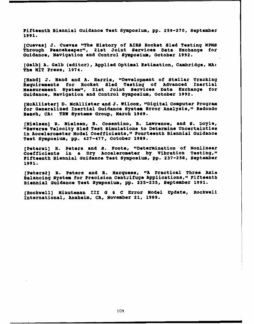
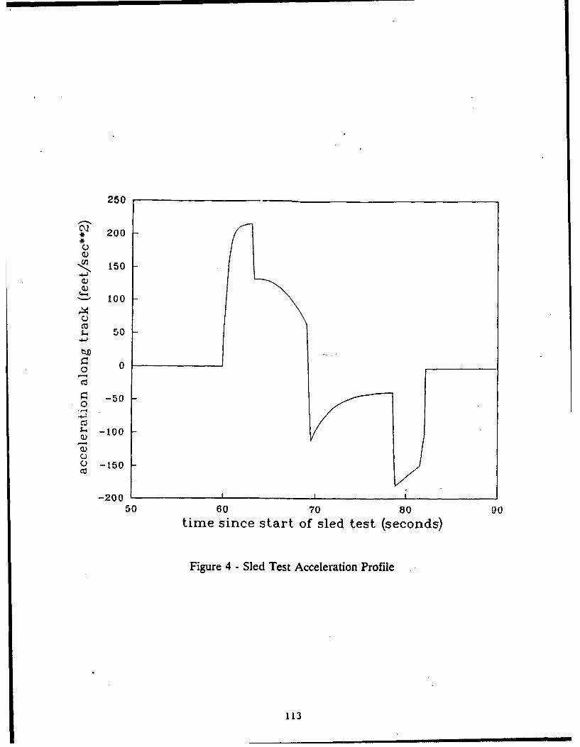
A Kalman filter has been implemented in a simulator program toestimate N8-20 guidance errors based on simulated sled test data.The start of the simulated sled track is located at 34 degreeslatitude, and the track runs due north (although in reality thetrack runs 4 degrees off of true north). The x-platform axis ofthe N8-20 points along the sled track. Figure 3 shows the N8-20geometry. The sled test software applies a constant torque to theN8-20 to maintain it in a locally level orientation (with respectto the launch point). One important result of this torquing isthat acceleration-sensitive N8-20 errors are driven by realacceleration (with respect to inertial space) rather than by theacceleration which is sensed by the accelerometers (which includesacceleration due to gravity). The simulated sled accelerationlasts for 80 seconds, although the acceleration during the last 50seconds or so is fairly low, as the sled is simply coasting to astop. The acceleration varies between -5.6 and 6.7 g's, and thevelocity reaches a maximum of 850 miles per hour. By the time thesled stops moving, it has travelled slightly over 4 miles. Thesled test includes 60 seconds of pre-run and 60 seconds of post-rundata collectio, sandwiched around the 80 seconds of hot-run datacollection, fo. a total of 200 seconds of test time. The sledtrajectory acceleration which was used is shown in Figure 4, andwas obtained from an analytical approximation found in [Aiyawar].
The covariance part of the Kalman filter was propagated duringthe 200 seconds of the sled test at a 100 Hz rate to determine theincrease of information that would result from a sled test. Thestate of the Kalman filter is composed of N5-20 errors [Rockwell].Since the errors are assumed to be constant during the duration ofthe sled test, the state transition matrix of the linear system isthe identity matrix and the process noise is zero. The measurementof the system is the difference between the NS-20-indicatedvelocity and the track-indicated velocity. The measurement matrixis therefore the sensitivity of the N8-20-indicated velocity to theN8-20 errors [McAllister]. The Kalman filter covariance is thuspropagated as follows [Gelb]:
Xk = Pk-I HkT (Hk Pk-1 "k' + Rd
Pk = (I --k Bk) Pk-1
where K is the Kalman filter gain, R is the covariance of themeasurement noise, H is the measurement matrix, I is the identitymatrix, and P is the covariance of the state estimate. The squareroots of the diagonal entries of P are the standard deviations ofthe state estimates. Note that the actual state estimate does notneed to be computed in order to compute the covariance matrix P.
The measurement noise values employed came from a PIGA noisemitigation method developed by Rockwell and currently used to
95

evaluate 1NU performance during N8-20 vibration tests. In thismethod the precise time of each PIGA pulse is determined therebyreducing pulse quantization standard deviation from 0.0346 feet persecond to noise that can be modelled by the equation
a = max (0.003, 0.0029 * g) (ft/sec).This equation means the standard deviation of the PIGA noise is themaximum of either 0.003 or 0.0029 times the absolute magnitude ofsensed acceleration in gs. Similarly, by this equation, the noisecan not be less than 0.003 feet per second.
The information gained about N8-20 error terms can bequantified by recovery ratios. The recovery ratio for an errorstate is the final standard deviation of the state estimate dividedby the initial standard deviation, so a low recovery ratiocorresponds to a better estimate and a greater increase ininformation. A recovery ratio less than approximately 0.5generally indicates that a significant amount of new informationhas been gained about the error state under consideration.
Table 1 shows the N8-20 recovery ratios for one standarddeviation magnitudes of the N18-20 error terms.It can be seen fromTable 1 that nine N8-20 errors are recoverable from an N8-20 sledtest if a slight latitude is extended in the 0.5 ratio criteria.Interpretation of this result, however, requires an understandingof which error terms are important contributors to impact miss.Observability of an error term that is insignificant to the NS-20CEP is of no value; observability of errors that are major misscontributors, however, is crucial to the determination of whetheror not sled tests can be used as a method to assess guidance systemaccuracy.
The N8-20 Error Nodel Document [Rockwell] identifies the majorsources of impact miss to be:
(1) Azimuth alignment error(2) Calibration error(3) Gyro g- and g 2-sensitivities (primarily B and 8 coefficients);(4) PIGA scale factor errors(5) Accelerometer input axis misalignments due to flight vibration
and shock; and(6) Deployment errors.
96

Table I - N8-20 Recovery Ratios
28-20 Error Onse-signa RecoveryRatios
Initial Con4itionsAzimuth 0.17West Alignment 0.23North Alignment 0.53
accelerometerz bias 0.S4y bias 0.72z bias 0.72z scale factor 0.31y scale factor 0.82z scale factor 0.82z input e_ 0.44y input i2 0.83z input j2 0.83
Gyroz bias 0.80y bias 0.43* bias 0.92
g-sensitive5B2 0.92Rai o.go8B1 1.00C2 0.82C1 0.98D2 1.00D1 0.89
g2 SensitiveB2 0.52B1 0.7332 1.0031 0.17132 0.96FAL 1.00FB1 1.00
97
Clearly, item (6) cannot be monitored with sled testing.
Item (5) will be observable by comparison of calibration databefore and after the sled test run.
When the analysis indicated some of the important error terms werenot observable at one standard deviation, additional analyses wererun with each of these unobservable errors increased to a threestandard deviation magnitude one at a time.
Item (4), PIGA scale factor, is observable, at one sigma on the zPIGA and three sigma on the y and s PIGAS (both y and • ratiosdropped to 0.43 at three sigma).
For item (3), the B2 error term is observable at one sigma and B1becomes observable at three sigma (ratio 0.34). The 8 coefficientsratios (0.62 and 0.57 respectively) indicate they might becomeobservable at slightly larger values.
Many of the elements of the calibration error, item (2), are due tomisalignment between the alignment reference block and the flightinstruments (PIGAS and G6 gyros). These errors manifest as azimuthalignment and level alignment errors, which have good observabilityin sled test.
Azimuth alignment, item (1), is readily observable even at onestandard deviation.
IV. POTENTIAL BENEFITS OF CONDUCTING AN NS-20 SLED TEST PROGRAM
As mentioned in the Introduction, the purpose of this study isto determine if there is benefit to be gained by sled testing themature NS-20 Guidance System. There is little incentive to conductsled tests to improve accuracy and/or reliability since the NS-20currently meets its requirements on both. It is postulated thatNS-20 sled tests could be used, however, as a monitor to identifyage-induced degradations in accuracy, functional performance,and/or reliability. As such, sled tests could augment themonitoring provided by the NS-20 flight test program which iscurrently limited to three flights per year after having been sixflights a year for a considerable period. Problems could bedetected and corrected as much as a year earlier than with flighttests alone.
For a sled test program to be a credible monitor for accuracydegradation of an aging system, however, the major flight errorsmust be excited by the sled test trajectory. The analysis
98

described in Section III was conducted to determine if this is thecase. It was shown that with the exception of the RV deploymenterror, most of the major in-flight errors are observable in sledtests if a three standard deviation magnitude is permitted for someof the error terms. For an accuracy degradation monitor this wouldprobably be acceptable. It thus appears that rocket sled testingwould be an effective test method to monitor NS-20 accuracydegradation.
If it is decided to initiate an NS-20 sled test program, it isenvisioned that this program might be patterned after thesuccessful AIRS sled test program, where each year three test runseach have been conducted on three guidance systems. Conductingsled tests on three NS-20 guidance systems would thus double thesample size of guidance systems tested in a dynamic environment(combining sustained acceleration, vibration, and shock), comparedto flight tests alone. The three runs per system provide insuranceagainst being unduly influenced by a single anomalous test run;combining each systems, three test results would produce morerepresentative performance than a single test.
The accuracy monitoring would be accomplished by comparing thetotal sled test guidance system error with the total guidancesystem error predicted by the NS-20 Error Budget. As long as theguidance system accuracy stayed within the one standard deviationboundariespredicted by the error budget, no further analysis wouldbe performed. Test results exceeding the boundaries would beanalyzed to determine -their cause. Test results indicating apattern of accuracy degradation with the passage of time, as mightbe expected with this aging system, would also be analyzed as tocause.
Functional performance would be monitored under a sled testprogram by reviewing functional signals for aberrant behavior.Reliability monitoring would be achieved by analyzing any guidancesystem failures.
V. SLED TESTING VERSUS OTHER TEST METHODS
There are several methods other than sled testing which can beused for testing a given guidance system. Some of these methodsare flight testing, centrifuge testing, vibration testing, andsubsystem/component testing. This section discusses the pros andcons of sled testing as compared to each of these alternatives.
V-A. SLED TESTS COMPARED TO FLIGHT TESTS
Minuteman III flight tests from Vandenberg Air Force Base(VAFB) are unquestionably more realistic approximations to anoperational mission than are rocket sled tests. A test flight
99

trajectory is quite similar to an operational trajectory. Theacceleration, vibration, and shock environments approximate thoseof operational launches.
Bled tests, however, offer the advantages that they cost muchless than flight tests. In addition, the guidance system is notexpended in a sled test so the same unit can be tested repeatedlyto obtain multiple measurements which has many advantages. A testprocedure can be modified and the test repeated on the same unit.Furthermore, calibration can be conducted before and after the sledrun to precisely measure any changes. The sled track provides avery precise reference for accuracy evaluation. The gi: •ancesystems can be oriented to improve error term observabili andchanges can be readily made to obtain additional data. Alý-.oughthe rocket sled test is a significantly les realisticapproximation of an actual operational Minuteman III mission thana VAPF flight test, it is the closest test to a flight test thatcan be done on the ground. It provides a unique combination offlight-like environments of sustained acceleration with someapplication of vibration and shock.
V-B. SLED TESTS COMPRZD TO CENRXWFUGE TMET8
Centrifuge tests could also be used to investigate N8-20performance [Peters2], but sled tests are the best ground testapproximation to flight tests. The centrifuge rotational method ofobtaining sustained g's departs significantly from an ICBXtrajectory simulation with a greater time to maximize acceleration.As a consequence, centrifuge tests aggravate gyro drift errors thatpersist for a shorter time during the ICBI boost phase of a flighttrajectory. This significantly complicates the use of centrifugetests as a method of assessing guidance system performance. Inaddition, existing centrifuges which are capable of testing the NO-20 lack sufficient accuracy for performance assessment. This isdue to such things as arm stretch and wobble, and the lack ofprecise position and velocity measurements for comparison to NS-20measurements. Centrifuge tests are less costly than sled tests.
V-C. SLED TESTS COMPARED TO VIBRATION TESTS
Vibration tests can provide a closer approximation to theflight test vibration environment (Burnett, Peteral], but cannotproduce the sled test linear acceleration which is key in assessingthe response of the guidance accelerometer under simulated flightand the platform gimbal structures and gimbal servos performanceunder inertial loading. Sled test vibration levels vary from testto test, but these levels are on the same order of magnitude asflight levels. Vibration testing is much less costly, however,than sled testing, and requires less test time. As a consequence,
100

many more systems can be tested in a given time frame and for agiven dollar cost.
V-D. SLED TESTS COMPARED TO SUBSYSTEM/COMPONUNT TESTS
When comparing sled tests to guidance subsystem/componenttests, sled testing has the advantage that the tests are on theentire guidance system in an environment that more realisticallyapproximates the mission. Tests at levels lower than the fullguidance system have the inherent risk that they may produceresults not fully representative of the guidance system as a unit.In addition, t.?sts on the full guidance system may help identifyunmodelled or inadequately modelled error terms. These error termsmay not be revealed in lower level testing, because either theenvironment cannot be duplicated, or the test procedure is notproperly designed to excite the error terms (since their existenceis either unknown or inadequately understood).
On the other hand, subsystem and component testing are muchless expensive than sled testing. Subsystem/component tests alsohave greater versatility in that more components can be tested andlarger sample sizes are easier to obtain.
Given the strengths and weaknesses of sled tests versussubsystem/component tests, the two test methods could be employedin conjunction. Subsystem/component tests could be used to analyzeproblems or anomalies found in sled tests.
VI. SLED TEST EQUIPMENT REQUIREMENTS AND SOFTWARE MODIFICATIONS
A major concern regarding the viability of NS-20 sled tests isthe identification of available guidance support equipment (GSB)that can meet the sled test requirements with few or nomodifications. If major modifications are required or nowequipment has to be designed and built, the development time andcost will weigh heavily against the value of the test.
As mentioned earlier, the N8-17 sled test program had used theFactory Test Equipment (FTE). At the time of the NS-17 tests in1973 and 1974, this FTE was fairly now and up-to-date. However,the N8-20 FTE is now relatively antiquated and is showing its agewith unreliability. It lacks many of the features of modern GSEand would consume a great deal of space in the sled trackblockhouse. The debugging of the test equipment software would alsobe difficult, and the availability of the N5-20 FTE is in doubt.
10)i
VI-o. ZAJDUAR
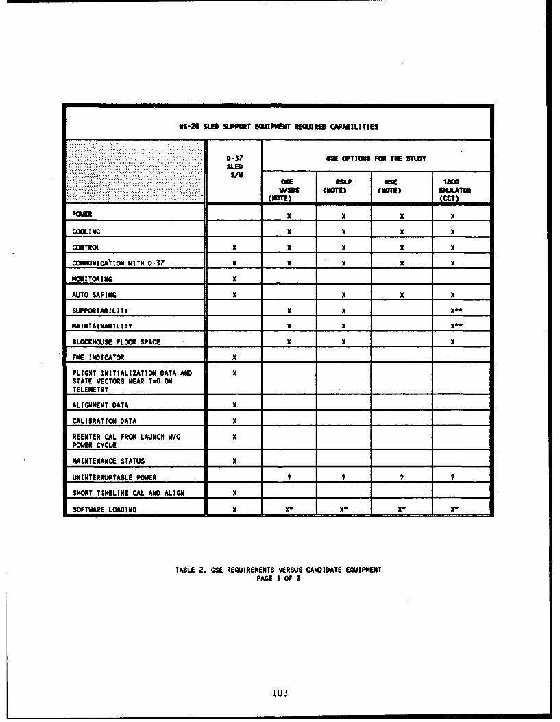
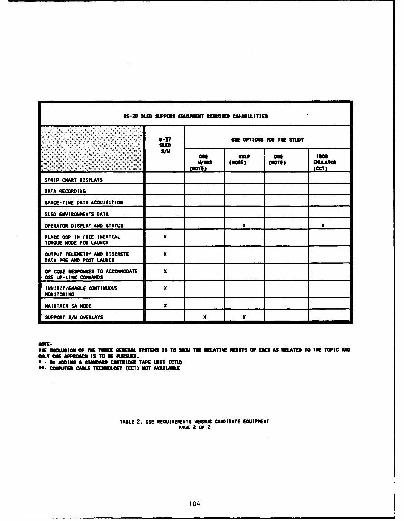
Before alternatives to the NS-20 FTE could be sought, themajor GBS requirements had to be defined. Theme requirements andthe GS candidates are summarized in Table 2 and discussed below.
The Operational Support Equipment (OS!) option consists of theprogrammer group, coupler, power supplies and chiller from thestandard launch facility. The launch control center function wouldbe supplied by the Squadron Data Simulator (SDS). The SDS can copysoftware overlay modifications from a test site launch controlcenter, thereby maintaining configuration with the current groundprogram. The primary advantage of this option is the low cost. Adisadvantage is that the sled software would need to utilize a setof operational commands to respond and execute sled uniquefunctions.
The Reentry System Launch Program (RSLP) equipment hascapabilities similar to the OSE. However, items such as groundprogram overlays are embedded in firmware, and changes could beprohibitively costly. The cost of a now set is unknown at thistime. Two sets of this equipment now exist at Vandenberg Air ForceBase in California, and are scheduled for use in supporting RSLPtest launches.
The Depot Support Equipment (DSE) and its emulator cannotcommunicate directly with the operational ground program. Thisoption would be most advantageous if the objectives of the sledtest were consistent with the use of the factory functionalsoftware in the 10 III flight computer.
A recent candidate not shown on the matrix is the hardnesssurveillance system control unit (HSSCU) which is also based upona very mature HP-1000 processor. This unit is now being evaluatedas to its potential in supporting a sled test software programenvisioned for the D-37.
The ability to load software and change the loaded software isa required feature of the test equipment. The ability to supportdirect memory addressing is also a desirable feature, but it is nota firm requirement if sufficient laboratory support for softwaretroubleshooting exists at another site.
102
iS-20 SLED SUPPOT EQUIPMENT REQUIRE CAPAILITIES
0-37 GSE OPTIONS FOR TE STUDY
S/VOSE RSLP DSE law0W/DS (mOTE) (CuTm) EMULATOR
(NmOTE) (CCT)
POWER x x x x
COOL I NG X X X X
CONTROL X X X X X
COMMUNICAYION WITH 0-37 X X X X X
MONITORING x
AUTO SAFING X X x
SUPPORTABILITY X X X*K
MAINTAINABILITY X X X**
BLOCKHOUSE FLOOR SPACE X X
FNE INDICATOR X
FLIGHT INITIALIZATION DATA AND XSTATE VECTORS NEAR TzO ONTELEMETRY
ALIGNMENT DATA X
CALIBRATION DATA X
REENTER CAL FROM LAUNCH W/O XPOWER CYCLE
MAINTENANCE STATUS X
UNINTERRUPTABLE POWER ?_?_? ?
SHORT TIMELINE CAL AND ALIGN X
SOFTWARE LOADING X X* X* X* X*
TABLE 2. GSE REQUIREMENTS VERSUS CANDIDATE EQUIPMENTPAGE 1 OF 2
103
ES-20 SLED SUPPOT EQUIPMENT REIE11 CAPABILITIES
0-3 ON OPTII FOR IR STUDYSLED_ _ _ _ __
"U/amE a"L DSE lawWING (NOTE) (NOTE) BILLATOR
_ _ _ _ _ _ _....._ (NOTE) __ _ _ _ (CCT)
STRIP CHART DISPLAYS_____________ ____ _________
DATA RECORDING ______ ____________
SPACE-TIME DATA ACQUISITION______ ______ ______ ______ ______
SLED ENVIRONMENTS DATA_____________ ___ __________
OPERATOR DISPLAY AND STATUS ______ ______ X ____ _ x
PLACE GSP IN FREE INERTIAL xTORMU MODE FOR LAUNCH_____________ ______ ____ ___ _______
OUTPUT TELEMETRY AND DISCRETE xDATA PRE AND POST LAUNCI4______ ______ ______ ______ ______
OP CODE RESPONSES TO ACCO OATE xOSE UIP-LINK COMMANDS I _____ _____ _____ _____
INHIUIT/ENABLE CONTINUOUS xHON!I TOR I ND______ ______G____________
MAINTAIN SA MODE x ______ ______ _____ __ ______
SIPORT S/W OVERLAYS xX
NOTE-TUE INCLUSION OF THE THREE GENERAL STSTIEMS is To SHOW TU RELATIVE NEITS; OF EACN AS RELATED TO TNE TOPIC AmOnLY 0E APPIUGCU IS TO BEPWSIN.
BY ADD UING A STANDARD CARTRIDGE TAPE UNIT (CUIi)COMPUTER CAKLE TECNNOLOGT (CCT) NOT AVAILABLE
TABLE 2. GSE REQUIREM4ENTS VERSUS CANDIDATE EQUIPMENTPAGE 2 OF 2
104

The test equipment must be supportable and easily maintainableby non-specialized contractor personnel and, upon occasion, testtrack personnel. Equipment which is not supported or not commonhas in tne past presented problems. The equipment must afford theoperator sufficient visibility and convenience for monitoring thetest progress, the general health of the test article, and criticalitems of the test equipment. This visibility is normally in theform of computer- generated displays, printouts, strip charts andmotors/readouts. A means of emergency power and cooling removal isalso required. Most of the equipment considered to date and shownin Table 2 meet or can be easily adapted through the use ofperipheral items to meet these requirements.
The conclusion to date regarding the selection of the GCE isthat its cost will be highly sensitive to the type of sled testsoftware used in the D-37. If the software chosen resembles theoperational ground program, then the OSE or RSLP suites can be usedwithout modifications. The remainder of the candidates wouldrequire software modification and would contain the attendantdevelopment costs.
VI--B. SLED SUPPORT EQUIPMENT
In addition to the GCE needed to support the guidance systemfor sled testing, there is a category of equipment needed for thetest itself, referred to herein as sled support equipment (SSE).This includes equipment such as the sled forebody, the rockets,cooling systems, etc. A review was conducted by the CentralInertial Guidance Test Facility (CIGTF) personnel to identify andassess the effort required to provide 883 needed for NS-20 sledtests. Although this was a preliminary analysis, CIGTF experiencewith other guidance system sled test programs enabled them toidentify with confidence the major items such as the forebody, thesled test instrumentation, the telemetry unit, miscellaneous groundequipment and the sled-borne coolant system.
The forebody would be a refurbished and modified unused assetfrom a previous program. This minimizes the cost and effort toprovide this major element of SSE. The remaining 8SE can beprovided by modifying equipment used on other programs as well.CIGTF foresees no obstacles or major cost items in any of the SSEneeded for the NS-20 sled tests.
The mechanical fixtures which attach and secure the testarticle would be chosen to simulate the vibration and attitudeflight environments. These fixtures would also be designed toprovide environmental protection, power, cooling, and data routingduring the testing. Data would be telemetered during the sled testby a radio frequency link, and simultaneously recorded on boardthe sled vehicle.
105
VI-C. BOFT WRN
The NS-20 software should be representative of the softwareaboard an operational MM III missile. Of paramount importance isthe capability to calibrate before and after the sled run withoutpower interruptions. In addition# the achievement of the launch-ready status for the sled test should replicate that of theoperational flight in order to avoid ambiguities in the results.These software operations should be identical in coding, and shouldreside on an identical NS-20 computer.
The sled launch mode for at least one run on each systemshould also replicate the missile flight mode in the torquing ofthe guidance instruments. Simulated flight navigation during thesled test allows the navigation data to be obtained in a positionframe, thereby smoothing the raw accelerometer data.
There are also other features to be incorporated in thesoftware in order to support the many different possible testobjectives. For example, control of and communication with theguidance platform and the test support equipment should beprovided. The platform and computer hardware should be monitored,and the self-test features of the software should be used todetermine the overall health of the system and to avoid anypotential damage. In response to a discrete issued by the sledtest program, power and cooling must be automatically removed toprevent damage. This feature is commonly referred to as auto-safingand will sometimes involve monitoring the communications. A lossof communication is interpreted as failure of either the NS-20 orthe GSE computer to service the communications link, and undercertain conditions is cause to terminate power and cooling. Anauto-safing summary of the critical events should be output inorder to effect the application and removal of the power andcooling sources. An indication of the change from launch-ready tolaunch mode should be telemetered in order to assist the post-testanalysis.
A software feature should be provided to allow rapid entry tolaunch mode. This will support simulated sled launches in order topractice activities which ensure launch team readiness. This so-called "short time line to launch", mode allows for practicing ofnormally lengthy sequences.
A method of re-entering calibration without power cyclingshould also be a feature of the test software. This feature willallow the assessment of any shifts of the instrument parametersacross the sled launch without risking parameter shifts whichfrequently occur with power cycling.
The ability to position the platform in an arbitrary attitudeis a candidate (unverified requirement) software feature. The
106

observability of platform errors may be enhanced by varying theplatform orientation.
In order to avoid a potentially lengthy qualification of thenow nonexistent sled software, a candidate software jump-off pointinvolving an existing qualified software program should bedetermined. The first of these candidates is the currentoperational ground program. This software would yield the mostrealistic attainment of strategiQ alert. Memory in the flightcomputer required for the sled software changes can be madeavailable by deleting the operational flight program. The secondcandidate for a jumping off point is the ground program previouslyused in the Fly-2 flight tests. The Fly-2 program had two NS-20platform/D-37 computers aboard a single missile.
Other software candidates for the jumping off point are alsounder consideration, but appear to contain calibration andalignment perturbations as compared to the operational groundprogram. This would result in an extensive verification effort.One of these candidates is the vibration test software, whichcontains the option to return to calibration and alignment afterthe test without power cycling. Another candidate is the factoryfunctional software which contains more extensive diagnostics thanany derivative of the operational ground program. Uponidentification of specific items or subsystems to be examined fordegradation post-test, this software could be an integral part ofachieving that objective. The pre and post-test execution of thissoftware on a sled test unit does not necessarily have to occur atthe sled test location, but could occur at either depot or factorysites.
VII. SUIIRY TAD CONCLUSIONS
The status of a conceptual study of sled testing theMinuteman III Guidance System (NS-20) has been presented. Sledtesting has proven to be of benefit to many ICBM guidance systems.Analytical findings show that sled testing will be of benefit tothe NS-20 as well. It appears that the primary benefit of sledtesting would be as a monitor to identify age-induced degradation,primarily in accuracy, but would also provide degradationinformation concerning functional performance and reliability. Asa consequence, it is possible that problems could be detected asmuch as a year earlier with NS-20 sled tests and flight testscombined than with flight tests alone.
Three serious concerns which could prevent a worthwhile sledtest program were addressed. Guidance system error observabilitywas determined by a covariance analysis. It was shown that, withthe exception of RV deployment error, the major error termsaffecting the guidance system CEP are observable in sled test
107

(although some error terms have to increase to three times theirerror budget values).
An area which is under investigation that nay enhance errorterm observability during sled testing is to include different NS-20 orientations.
It was mentioned that functional performance could bemonitored in sled tests by -reviewing functional signals foraberrant behavior. Reliability monitoring could be achieved byanalyzing guidance system failures which occur during the test. Inthis way, sled tests would augment the NS-20 flight test program,which is currently limited to three flights per year. Sled testswould thus double the sample size of guidance system tests in adynamic environment (combining acceleration and vibration).
The advantages and disadvantages of sled testing as comparedto other test methods were discussed. It was seen that sledtesting is unique, because it is the ground test which is most likea flight test. It is much less expensive, however, than flighttesting. Finally, the hardware and software requirements for anNS-20 sled test program were presented.
VIII. * ACWLEDGEXERNT8
This work has been performed in support of LTC Stu Flood,Guidance PMT Chief of the Sustainment Support Organization of theAir Force Systems Command, under contract number F04704-92-C-0005.The authors would like to thank the following personnel for theiruseful technical support during the course of this work: CaptainCurtis Coffman and Bob Lawrence of the 46th Test Group; GerryGrimaldi and Tom Williams of Rockwell International; and GoneHymas, Bruce Brown, Benjamin Frint, Bob Jesik, Nick Kfoury, DaveLarson, Richard Holdeman, and Ken Kosaka of TRW.
IX. REFER•NCZ8
[Aiyawar] R. Aiyawar, R. Boylan, and E. Graves, "AIRS/Sled TestSensitivity Analysis Report,"$ Cambridge, MA: The Charles StarkDraper Laboratory, June 1977.
(Bunco] K. Bunco and G. Grachis, "Utilization of Velocity ResidualSignatures to Determine Error Terms of Inertial Components andSystems in a Sled Test Environment," Fourteenth Biennial GuidanceTest Symposium, pp. 349-385, October 1989.
[Burnett] R. Burnett and R. Macary, "Design of Precision VibrationTest Station for High Accuracy Accelerometer Calibration,",
108
Fifteenth Biennial Guidance Test Symposium, pp. 259-270, September1991.
[Cuevas] J. Cuevas "The History of AIRS Rocket Sled Testing MPMSThrough Peacekeeper", 21st Joint Services Data Exchange forGuidance, Navigation and Control Symposium, October 1992.
[Gelb] A. Gelb (editor), Applied Optimal Estimation, Cambridge, MA:
The MIT Press, 1974.
[Hand] J. Hand and A. Harris, "Development of Stellar TrackingRequirements for Rocket Sled Testing of Advanced InertialMeasurement System"', 21st Joint Services Data Exchange forGuidance, Navigation and Control Symposium, October 1992.
[McAllister] D. McAllister and J. Wilcox, ,"Digital Computer Programfor Generalized Inertial Guidance System Error Analysis," RedondoBeach, CA: TRW Systems Group, March 1969.
[Nielsen] R. Nielsen, B. Cosentino, R. Lavrence, and S. Doyle,",,Reverse Velocity Sled Test Simulations to Determine Uncertaintiesin Accelerometer Model Coefficients,"# Fourteenth Biennial GuidanceTest Symposium, pp. 427-477, October 1989.
[Petersl] R. Peters and S. Foote, '"Determination of NonlinearCoefficients in a Dry Accelerometer by Vibration Testing,"9Fifteenth Biennial Guidance Test Symposium, pp. 237-258, September1991.
[Peters2] R. Peters and R. Marquess, "@A Practical Three AxisBalancing System for Precision Centrifuge Applications," FifteenthBiennial Guidance Test Symposium, pp. 225-235, September 1991.
(Rockwell] Minuteman III G & C Error Model Update, RockwellInternational, Anaheim, CA, November 21, 1989.
109

&J
0
Lu v 0 0
u C-
4) 0 ex E
to ri. &j
E
LLJ
LoU) V)
Cr) DQ- F-
LLJ uLJ u
F- V)ui
Lli. Li 0u 0< F- w0-U) <
cr LLDuu En
CCw0cc0Uwcc
wCL
F-
0cr
0coI
z0
110

.4
0n 0) ri
E 4 cn
ow cz
>r - Q
04 u
z0-
F-i
<
0 c,
o 000 - <4
L)4c LL.J N>
Cl) r,4
C~) 0.. -0
0 ~0
0 0
- ~0 z
D-U
W0 EnIcc wl
D LU
'-<
w (n I--1!

00 '3
0 Cd 4
Ln con
0 0
CD 0
o ) 0 t2
I o
> (n
c -I-
Goo
03 (
4-A-
- 0
112
250
C\I* 200Q0.
S.150
---- 100
CO50
t00
0
Cz
o-150-
-20050 60 70 80 90
time since start of sled test (seconds)
Figure 4 - Sled Test Acceleration Profile
113