Embed Size (px)
Citation preview

A CLASSIC SMALL INCINERATOR CASE: THE REBUILD AT LEVIS, QUEBEC
Andrew Haberl, eng. Technology Group Procedair Industries Inc. Montreal, Quebec Canada
ABSTRACT
The MSW incinerator in Levis, Canada, was upgraded in 1998 to include improved combustion controls, a dry scrubbing system, and a CEMS. The project went ahead despite the fact that the economic driving forces for a conversion to EFW were not there. Rather, it was government initiative, primarily to improve emissions, that made the retrofit a reality. As a result, the project was highlighted by a variety of interesting design details, which are reviewed in detail. Operating and emissions results are presented.
INTRODUCTION
The municipal waste incinerator at Levis, Quebec, has been accepting garbage from several local communities in the area for over twenty years. A schematic diagram of the simple system, along with key design parameters, is shown in Figure 1. It is owned and operated by La Regie Intermunicipale de Gestion des Dechets de la Rive Sud du Quebec (R.I.G.D.R.S.Q.), which is a public organization that is amicably known as the 'Regie'. Although originally designed to handle 65 TPD, it has been processing more than that amount for some time, and generating more than its share of unburned solids in the process.
Throughout the early 1990's, several options for using the waste energy were evaluated, including steam generation for an adjacent oil refinery and a small electric generation system. However, the economic feasibility of these schemes was limited, given the local energy market conditions. But the provincial government and the local community were highly motivated to improve the plant's emissions performance. So in 1996, the decision was finally taken to modernize the combustion process and upgrade capacity at the facility, and to add a state-of-theart scrubbing system at the same time. The Regie
191
engaged the services of Polygec, Inc. (a division of SNCLavalin) as its engineering consultant.
The overall project was awarded by the Regie to Tecksol Inc., in a joint turnkey bid with Procedair Industries Inc., in January, 1997. The system was installed in the spring and summer of 1998, and started up over the fall. The plant was shut down for a period of five weeks in August/September for the furnace rebuild and scrubber tie-in, and has been operating at the new capacity ever since.
Figure 1: System Configuration Before Rebuild
Flue Gas Outlet
t
Solids Disposal
0:::::::::::::===========9
There were three unique challenges with the project. Firstly, because of the lack of an energy-from-waste driving force, the project's feasibility was based on a very tight balance of capacity, resource consumption, and waste generation. Hence strict limits were placed on consumption of fuels, utilities, reagents, and even spare parts for the system, and the contractors were asked to guarantee them all. Secondly, the plant had succeeded in managing for many years with a minimum of operating

and maintenance staff, who were very used to the simplicity and flexibility of their existing equipment. So making the transition to a more complex system with stricter emissions control requirements without an increase in staff was a key issue. And finally, the incinerator was shut down every 2-3 weeks because of lack of a refuse stream, so the new system had to be easily stopped and started while maintaining the best possible emissions performance.
INCINERATOR MODIFICATIONS
Tecksol Inc. provided the engineering, supply, and installation of the furnace upgrade. Existing equipment was re-used where possible, although the existing cooling tower and electrostatic precipitator were removed. The key design parameters of the upgraded system are shown in Table I. The rebuilt furnace was designed to handle a greater amount of garbage, to minimize NO. emissions, and to destroy any VOC's that may be generated. The key features of the rebuild are as follows.
Table 1: Design Parameters After Rebuild
Design capacity 80 MTPD
Type of APC system Dry Lime Injection
Afterburner Yes, for VOC destruction.
Secondary air Yes, controlled automatically
Energy recovery Still none
Improved Furnace Controls
The scope of work included a new PC-based central control system. It permits trending and optimization of process parameters at a level which was not possible with the old equipment. Virtually all existing controls were outdated and hence mothbal1ed. Using the new system, al1 start-up and shut-down steps were automated such that the entire plant can now be started up in response to a single command. This was important in view of the limited operating manpower and frequent interruptions to the waste stream.
Tecksol's mandate also included destroying VOC's while meeting capacity targets and limits for unburned garbage. Hence the air for combustion is careful1y controlled using a series of strategical1y-located thermocouples and dampers to keep the furnace optimized at all times. Although there was a period of optimization of the thermocouples and the control logic, the result has been a
192
vastly improved garbage burning process with increased capacity and reduced solid wastes.
New Oil Burner
To compensate for variability in the burning process, a 30 MMBtulhr oil burner was added to the top of the furnace chamber. It is ignited when necessary to maintain an exhaust temperature of 1000"F at all times. As a result, VOC emissions from the plant are significantly reduced. The burner is retractable for on-line maintenance and is shown in Figure 2.
Figure 2: New Oil Burner
Continuous Emissions Monitoring System
Compliance is ensured with the support of a new Bomem multi-variable stack gas monitor. It monitors HCl, NOx, and combustion gases and alerts the operator if ever emissions exceed limits. Stack gas opacity is also tracked.
THE PROCEDAIR ALL-DRY SCRUBBER
Principle of Operation
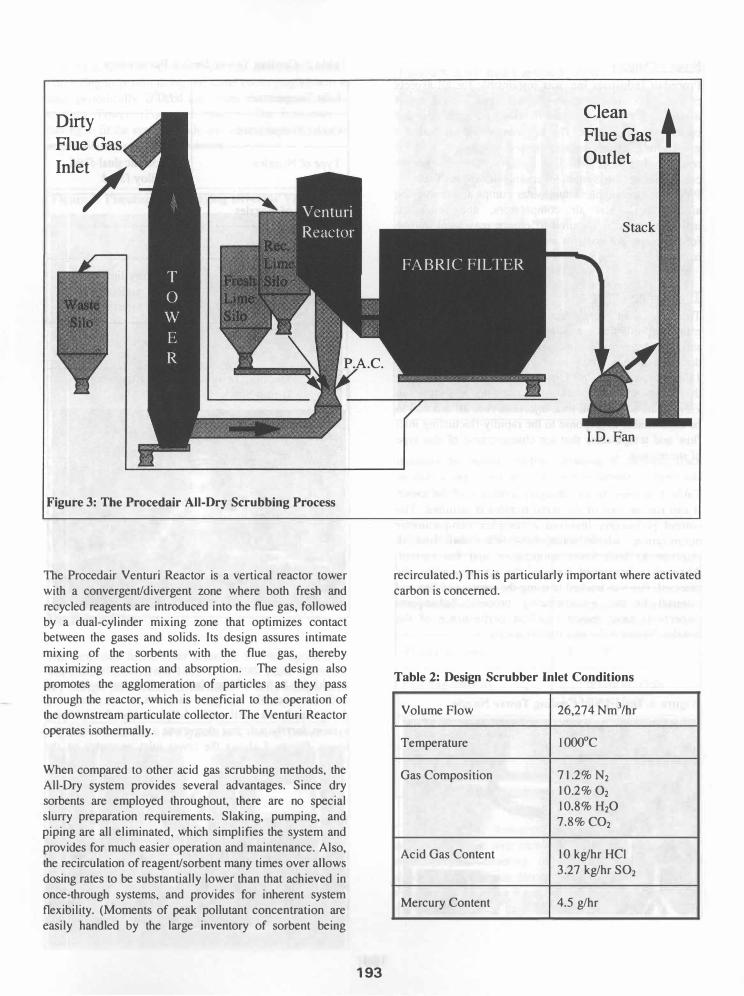
The Procedair All-Dry Scrubbing System controls pollutant emissions by reacting them with dry reagents to form inert salts. The process is illustrated in Figure 3. Flue gas from the municipal waste combustor, containing particulate, acid gas constituents, metals and organic compounds, is ducted first into a co-current Cooling Tower to achieve the optimum reaction temperature and flue gas moisture. It then enters the heart of the All-Dry scrubbing process, the Procedair Venturi Reactor. From there, the flue gas passes through a multi-module pulse jet Fabric Filter to collect the solids on the bags, and then exits via an Induced Draft Fan and up the stack to atmosphere. Since the collected solids contain significant amounts of unused sorbent, most are recycled back to the Venturi Reactor for re-use. A portion of the recycle stream is diverted to a silo for disposal.
Dirty
Flue
Inle/
Figure 3: The Procedair All-Dry Scrubbing Process
The Procedair Venturi Reactor is a vertical reactor tower with a convergent/divergent zone where both fresh and recycled reagents are introduced into the flue gas, followed by a dual-cylinder mixing zone that optimizes contact between the gases and solids. Its design assures intimate mixing of the sorbents with the flue gas, thereby maximizing reaction and absorption. The design also promotes the agglomeration of particles as they pass through the reactor, which is beneficial to the operation of the downstream particulate collector. The Venturi Reactor operates isothermally.
When compared to other acid gas scrubbing methods, the All-Dry system provides several advantages. Since dry sorbents are employed throughout, there are no special slurry preparation requirements. Slaking, pumping, and piping are all eliminated, which simplifies the system and provides for much easier operation and maintenance. Also, the recirculation of reagent/sorbent many times over allows dosing rates to be substantially lower than that achieved in once-through systems, and provides for inherent system flexibility. (Moments of peak pollutant concentration are easily handled by the large inventory of sorbent being
193
Clean
Flue Gas
Outlet
1.0. Fan
+
recirculated.) This is particularly important where activated carbon is concerned.
Table 2: Design Scrubber Inlet Conditions
Volume Flow 26,274 Nm%r
Temperature IOOO°C
Gas Composition 71.2% N2 10.2% O2 10.8% H2O 7.8% CO2
Acid Gas Content 10 kglhr HCI 3.27 kglhr S02
Mercury Content 4.5 glhr

· Scope of Supply
Procedair Industries Inc. was responsible for all aspects of the air pollution control system at Levis. This included the engineering, design, fabrication, construction, and commissioning phases. The key components included a gas cooling tower, venturi reactor, baghouse, and all reagent and waste handling systems. Design process conditions at the system inlet are shown in Table 2. Procedair also supplied dual water pumps and conveying air blowers, dual air compressors, and redundant instrumentation as required to ensure maximum uptime for the plant. All controls and instrumentation were also included.
The Cooling Tower
The lack of an energy recovery system on the furnace meant not only that a cooling tower was required for the scrubber, but that the tower sizing presented a significant design challenge. The gases had to be cooled from over 1800"F to as low as 285"F in a single pass, while insuring that that bottom of the tower remained dry at all times in view of the subsequent lime injection. And all this had to be controllable in response to the rapidly-fluctuating inlet flow and temperature that are characteristic of this type of incinerator.
Table 3 outlines the key design parameters of the tower. It can run on two of the three nozzles if required. The control philosophy involved a complex two-parameter optimization, where water flow was modulated in response to both tower temperature and fan current. Although a premature wear of the spray nozzles was detected, this was tracked to using the wrong welding rod material in the manufacturing process. Subsequent inspections have shown excellent performance of the nozzles. Figure 4 shows a typical nozzle.
Figure 4: Dual-Fluid Cooling Tower Nozzle
194
Table 3: Cooling Tower Design Parameters
Inlet Temperature IOOO°C
Outlet Temperature 140°C
Type of Nozzles Turbosonic dual-fluid, Hastelloy-faced
Quantity of Nozzles Three
Height of Tower 76 feet
Surface Coating Refractory-lined upper section, anticorrosion-painted lower section
Figure 5: Cooling Tower Inlet with Emergency Dump Stack
In addition to these design features, the tower is equipped with a retractable top plate that acts as an emergency dump stack, as well as a fully-automated conveying system for fly ash that drops out at the bottom of the tower. Figure 5 shows the tower inlet geometry on the roof.
Lime In jection
The reagent used for acid gas co�rol in this application is hydrated lime, Ca(OH)2. The lime reacts with the acid gas constituents (HCI, S02, HF) to form inert salts. Reaction products from the fabric filter are recycled pneumatically back to a silo and fed by gravity into the Venturi Reactor. An interesting feature of this application

· is that a divertor valve is incorporated into the pneumatic conveying to permit using the same conveying system to also periodically collect ash from the bottom of the Cooling Tower. (Figures 6 and 7). The limitation of having to fit the system inside an existing building was an important factor in these decisions.
Figure 6: Pneumatic Conveying Divertor Valve
Activated Carbon Injection
To capture mercury and dioxinlfuran compounds, the system is equipped with a powdered activated carbon injection system. The activated carbon is supplied in bulk bags and injected separately at the throat of the Venturi Reactor for optimum dispersion and maximum effect. The feed system is equipped with a variable speed drive to optimize consumption. Figure 8 shows this equipment as it was installed.
The Fabric Filter
The Procedair fabric filter installed for this application was a model SONAIR 4-1415-195-4290. Table 4 lists the key design parameters. It included 4 fully-independent
Figure 7: Collection of Fly Ash at Cooling Tower
195
Figure 8: Activated Carbon System
modules to permit off-line cleaning if desired. Each module is equipped with its own pyramidal hopper and rotary valve.
Table 4: Fabric Filter Design Details
Bag dimensions 6" diameter & 14' long
Bag material Fiberglass with Teflon B coating, 22 oz/yd2
Total filter area 17,157 ft2
Filtering velocity 2.23 ftlmin GROSS 2.97 ftlmin NET
Cleaning air pressure 50 psig
Bag access method Removable top doors with overhead crane
The fabric filter features Procedair's proprietary cage design, complete with custom-contoured venturi cap for optimum pulse cleaning. It is also is equipped with a double-poppet bypass damper to protect the bags against system upset. Figures 9 and 10 show the lower and upper views, respectively.

SYSTEM PERFORMANCE
Capacity, Utilities, & Waste Generation
The tight project economics necessitated very close tracking of all operating costs. Table 5 shows the agressiveness of the targets, which were specified contractually for key variables in the equation. A detailed formula for sharing the long-term costs of anything in excess of these limits was developed, and a six-month trial will begin in 1999. Preliminary indications over the first several months of operation, however, are that all parameters are well within the targeted values.
Stack Emissions Results
Table 6 lists the results of the performance test, which was done in December, 1998 by the Envirolab division of Roche Ltee. Particulate, acid gases, NO., heavy metals, and several other pollutants were measured using EPAspecified methods. Careful attention was paid to ensure that reagent consumptions were kept below the contractual limits. Lawson and Aube (1999) noted that all results were well within the norms recommended by the
Figure 10: On Top of the Fabric Filter
196
CCME, and far below the limits set by the provincial government. The EPA limits are added in Table 6 for conparison. They were also all easily met.
Table 5: Guaranteed Scrubber Operating Costs·
Hydrated Lime Consumption 150 T/yr
Activated Carbon 7.9 T/yr Consumption
Electricity Usage 2,061 ,240 KWHlyr
Fly Ash Disposal 618 T/yr
Disposal of Reaction Products 210 T/yr
Process Water Usage 22,072,723 Gimp'/yr
SUMMARY
Procedair's All-Dry Scrubbing System has shown its value in another MSW incinerator application. The system started up well and has been operational since September, 1998. Emissions were brought into line within two weeks of start-up. Control loop optimization, operator training, and clean-up of technical and contractual details were completed over the subsequent months. The performance test showed very good results.
The plant is now operating comfortably in the new regime and long-term measurement of utility and reagent consumption is under way. Key objectives in terms of operating costs appear to have been met. The apparent lack of sufficient economic feasibility for an energyfrom-waste retrofit, however, presents an important area for future study.
REFERENCES
Lawson, L., and Aube, F., 1999, "Rapport d'Echantillonnage et d' Analyse des Gaz de Combustion Incinerateur des Dechets de la R.I.G.D.R.S.Q.", Envirolab, Sainte-Foy (Quebec), p.44
..
I Based on 330 days/year operation at 80 tons/day.

Table 6: Stack Emission Test Results
Parameter2 Measured Value
Particulate (mglNm3) 7.5
HC} (ppm) 24 ..
S02 (ppm) I
CO (ppm) I
NO. (ppm as N02) 102
DioxinslFurans (nglNm3) 0.03
As (uglNm3) <0.3 Cd (uglNm3) <8 Cr (uglNm3) <6 Pb (uglNm3) <6 Hg (uglNm3) <15
Detected HAP's (uglNm3) 1.7
PCB's (uglNm3) <0.1
Detected Chlorophenols (uglNm3) 1.15
Detected Chlorobenzene (uglNm3) 0.3
2 All data corrected to II % oxygen. 3 Although the plant qualifies as a small plant, large-plant retrofit limits (more stringent) are listed here since the small-plant limits are under review. 4 The small-incinerator limit is 177 ppm. 5 The test report discusses a ±I 0% accuracy for this measurement, and hence concludes it is acceptable.
197
CCME Limit EPA Limie
20 27
50 224
100 22
50 50
210 210
0.5 30
I n1a 100 40 10 n1a 50 490
200 80
5 n1a
I n1a
I n1a
I n1a