Embed Size (px)
Citation preview
An Introduction to Incinerator Emissions and Permitting Course No: C03-043
Credit: 3 PDH
J. Paul Guyer, P.E., R.A., Fellow ASCE, Fellow AEI
Continuing Education and Development, Inc. 9 Greyridge Farm Court Stony Point, NY 10980 P: (877) 322-5800 F: (877) 322-4774 [email protected]
J. Paul Guyer, P.E., R.A. Paul Guyer is a registered civil engineer, mechanical engineer, fire protection engineer and architect with 35 years of experience designing buildings and related infrastructure. For an additional 9 years he was a principal staff advisor to the California Legislature on capital outlay and infrastructure issues. He is a graduate of Stanford University and has held numerous national, state and local offices with the American Society of Civil Engineers, Architectural Engineering Institute and National Society of Professional Engineers.
An Introduction to Incinerator Emissions and Permitting
© J. Paul Guyer 2013 1
CONTENTS 1. INCINERATOR EMISSIONS 2. STACK EMISSION REGULATIONS AND THE PERMITTING PROCESS
3. MEASURING TECHNIQUES (This publication is adapted from the Unified Facilities Criteria of the United States government which are in the public domain, have been authorized for unlimited distribution, and are not copyrighted.)
© J. Paul Guyer 2013 2
1. INCINERATOR EMISSIONS 1.1 INCINERATION This publication describes and quantifies, whenever possible, the
air pollution particulate emissions which are the direct result of the incineration process.
1.1.1 INCINERATION PROCESS. The incineration process consists of burning solid,
semisolid, liquid, or gaseous waste to produce carbon dioxide, water, and ash. It is an
efficient means of reducing waste volume. The solid, incombustible residue of
incineration is inert, sanitary, and sensibly odorless.
1.1.2 EMISSIONS. Incineration contributes to air pollution. The polluting emissions are
ash, hydrocarbons, sulfur oxides (SOX), nitrous oxides (NOX), chlorides, and carbon
monoxide. Estimating absolute quantities of these pollutants is not an exact science, hut
historical testing data from typical incinerators allow estimates of emissions to be made.
Also, measurement methods for incinerator emissions are sufficiently advanced to
permit actual data to be obtained for any existing incinerator. These measurements are
preferred in all cases over analytical estimates.
1.1.3 POLLUTION CODES. Air pollution particulate emissions must be considered as
they relate to the federal, state and local pollution codes. In general, incinerators cannot
meet current pollution code requirements without particulate control devices.
1.2 TYPES OF INCINERATOR WASTE MATERIALS. Waste materials are classified
as shown in Table 1. An ultimate analysis of a typical general solid waste is shown in
Table 2. Because of the wide variation in composition of waste materials, an analysis of
the actual material to be incinerated should be made before sizing the incineration
equipment.
© J. Paul Guyer 2013 3
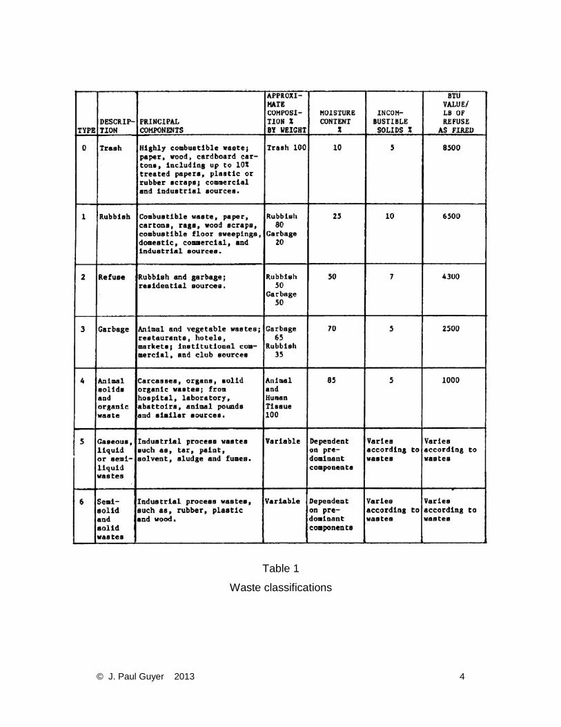
Table 1
Waste classifications
© J. Paul Guyer 2013 4
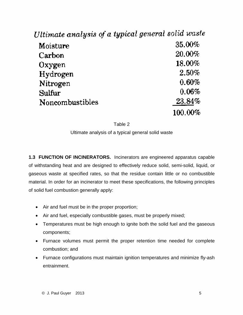
Table 2
Ultimate analysis of a typical general solid waste
1.3 FUNCTION OF INCINERATORS. Incinerators are engineered apparatus capable
of withstanding heat and are designed to effectively reduce solid, semi-solid, liquid, or
gaseous waste at specified rates, so that the residue contain little or no combustible material. In order for an incinerator to meet these specifications, the following principles
of solid fuel combustion generally apply:
• Air and fuel must be in the proper proportion;
• Air and fuel, especially combustible gases, must be properly mixed;
• Temperatures must be high enough to ignite both the solid fuel and the gaseous
components;
• Furnace volumes must permit the proper retention time needed for complete
combustion; and
• Furnace configurations must maintain ignition temperatures and minimize fly-ash
entrainment.
© J. Paul Guyer 2013 5
1.4 EFFECT OF WASTE PROPERTIES. The variability of chemical and physical
properties of waste materials, such as ash content, moisture content, volatility, burning
rate, density, and heating value, makes control of incineration difficult. All of these
factors affect to some degree the operating variables of the flame-propagation rate,
flame travel, combustion temperature, combustion air requirements, and the need for
auxiliary heat. Maximum combustion efficiency is maintained primarily through optimum
incinerator design. 1.5 TYPES OF INCINERATORS.
1.5.1 MUNICIPAL INCINERATORS. Incinerators are classified either as large or small
units, with the dividing point at a processing rate of 50 tons of waste per day. The trend
is toward the use of the smaller units because of their lower cost, their simplicity, and
lower air emission control requirements. There are three major types of municipal
incinerators discussed below.
1.5.1.1 RECTANGULAR INCINERATORS. The most common municipal incinerator is
the rectangular type. The multiple chamber units are either refractory lined or water
cooled and consist of a combustion chamber followed by a mixing chamber. The multi-
cell units consist of two or more side-by-side furnace cells connected to a common
mixing chamber. Primary air is fed under the grate. Secondary air is added in the mixing
chamber to complete combustion. A settling chamber often follows the mixing chamber.
Ash is removed from pits in the bottom of all of the chambers
1.5.1.2 VERTICAL CIRCULAR INCINERATORS. Waste is usually fed into the top of
the refractory lined chamber. The grate consists of a rotating cone in the center
surrounded by a stationary section with a dumping section around it. Arms attached to
the rotating cone agitate the waste and move the ash to the outside. Primary air is fed
underneath the grate. Overfire air is fed into the upper section of the chamber.
© J. Paul Guyer 2013 6
1.5.1.3 ROTARY KILN INCINERATORS. Rotary kiln incinerators are used to further the
combustion of waste that has been dried and partially burned in a rectangular chamber.
The waste is mixed with combustion air by the tumbling action of the kiln. Combustion is
completed in the mixing chamber following the kiln where secondary air is added. The
ash is discharged at the end of the kiln.
1.5.2 INDUSTRIAL AND COMMERCIAL INCINERATORS. Industrial and commercial
incinerators generally fall into six categories discussed below. The capacities of these
incinerators generally range from a half to less than 50 tons per day. They are usually
operated intermittently.
1.5.2.1 SINGLE CHAMBER INCINERATORS. Single chamber incinerators consist of a
refractory lined combustion chamber and an ash pit separated by a grate. There is no
separate mixing chamber. An auxiliary fuel burner is normally provided underneath the
grate. The units are normally natural draft (no fans). Emissions from single chamber
units are high because of incomplete combustion.
1.5.2.2 MULTIPLE CHAMBER INCINERATORS. Multiple chamber refractory lined
incinerators normally consist of a primary chamber, a mixing chamber and a secondary
combustion chamber. The primary chamber is similar to a single chamber unit. Air is
fed under the grate and through overfire air ports. Secondary air is added in the mixing
chamber. Combustion is completed in the secondary combustion chamber where some
settling occurs. These units are also normally based on natural draft.
1.5.2.3 CONICAL INCINERATORS. Conical incinerators known commonly as "tee-pee"
burners have been used primarily in the wood product industry to dispose of wood
waste. Since they cannot meet most local particulate emission requirements, and since
wood waste is becoming more valuable as a fuel, conical incinerators are being phased
out.
© J. Paul Guyer 2013 7
1.5.2.4 TRENCH INCINERATORS. Trench incinerators are used for the disposal of
waste with a high heat content and a low ash content. The incinerator consists of a U-
shaped chamber with air nozzles along the rim. The nozzles are directed to provide a
curtain of air over the pit and to provide air in the pit.
1.5.2.5 CONTROLLED-AIR INCINERATORS. Controlled-air incinerators consist of a
refractory lined primary chamber where a reducing atmosphere is maintained, and a
refractory lined secondary chamber where an oxidizing atmosphere is maintained. The
carbon in the waste burns and supplies the heat to release the volatiles in the waste in
the form of a dense combustible smoke. Overfire air is added between chambers. The
smoke is ignited in the secondary chamber with the addition of air. Auxiliary fuel burners
are sometimes provided in the secondary chamber if the mixture does not support
combustion. Air for this type of incinerator is provided by a forced draft fan and is
controlled by dampers in order to provide the proper distribution. Controlled-air
incinerators are efficient units with low particulate emission rates.
1.5.2.6 FLUIDIZED BED INCINERATORS. Fluidized bed incinerators consist of a
refractory lined vertical cylinder with a grid in the lower part that supports a bed of
granular material, such as sand or fine gravel. Air is blown into the chamber below the
grid causing the bed to fluidize. Waste is fed above the bed and then mixes with the
media where it burns. Fluidized bed incinerators are normally self-sustaining and
require an auxiliary fuel burner only for startup. Fluidizing air is supplied by a centrifugal
blower. Ash leaves the fluidized bed incinerator when it becomes fine enough to be
carried out by the flue gas. Fluidized bed incinerators are capable of burning most
types of liquid or solid waste.
1.5.3 SLUDGE INCINERATORS. Sludge incinerators handle materials high in water
content and low in heat content. Two types of incinerators are normally used for sludge
Incineration and are discussed below.
© J. Paul Guyer 2013 8
1.5.3.1 MULTIPLE HEARTH INCINERATORS. Multiple hearth incinerators consist of
vertically stacked grates. The sludge enters the top where the exiting flue gas is used to
drive off the moisture. The burning sludge moves through the furnace to the lower
hearths. Ash is removed from under the last hearth.
1.5.3.2 FLUIDIZED BED INCINERATOR. Fluidized bed incinerators are particularly well
suited for sludge disposal because of the high heat content of the bed media. Heat from
the combustion of the sludge is transferred to the bed media. This heat is then
transferred back to the incoming sludge, driving off the moisture.
1.6 PARTICULATE EMISSION STANDARDS. The Clean Air Act requires all states to
issue regulations regarding the amount of particulate emission from incinerators. Each
state must meet or exceed the primary standards set forth by the federal act, limiting particulate emissions for incinerators with a charging rate of more than 50 tons per day
of solid to .08 grains per standard cubic foot (gr/std ft3) of dry gas at 12 percent carbon
dioxide (CO2). Federal guidelines for sewage sludge incinerators limit emissions to 1.3 pounds (lbs) per ton of dry sludge input and opacity to 20 percent maximum. No federal
guidelines currently exist for gaseous emissions. State and local regulations may meet
or exceed the federal guidelines. These regulations are subject to change and must be
reviewed prior to selecting any air pollution control device. 1.7 PARTICULATE EMISSION ESTIMATING. In order to select a proper pollution
control device, the quantities of particulate emissions from an incinerator must be
measured or estimated. Measurement is the preferred method. For new incinerator
installations where particulate emissions must be estimated, Tables 3 and 4 should be
used unless concurrent data guaranteed by a qualified vendor is provided.
1.7.1 FACTORS AFFECTING EMISSION VARIABILITY. The quantity and size of
particulate emissions leaving the furnace of an incinerator vary widely, depending upon
such factors as incinerator design, refuse type, incinerator capacity, method of feeding,
© J. Paul Guyer 2013 9
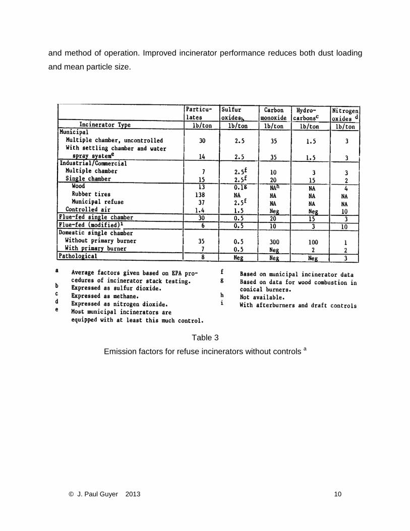
and method of operation. Improved incinerator performance reduces both dust loading
and mean particle size.
Table 3
Emission factors for refuse incinerators without controls a
© J. Paul Guyer 2013 10
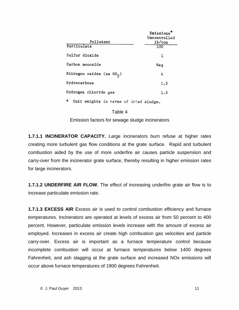
Table 4
Emission factors for sewage sludge incinerators
1.7.1.1 INCINERATOR CAPACITY. Large incinerators burn refuse at higher rates
creating more turbulent gas flow conditions at the grate surface. Rapid and turbulent
combustion aided by the use of more underfire air causes particle suspension and
carry-over from the incinerator grate surface, thereby resulting in higher emission rates
for large incinerators.
1.7.1.2 UNDERFIRE AIR FLOW. The effect of increasing underfire grate air flow is to
increase particulate emission rate.
1.7.1.3 EXCESS AIR Excess air is used to control combustion efficiency and furnace
temperatures. Incinerators are operated at levels of excess air from 50 percent to 400
percent. However, particulate emission levels increase with the amount of excess air
employed. Increases in excess air create high combustion gas velocities and particle
carry-over. Excess air is important as a furnace temperature control because
incomplete combustion will occur at furnace temperatures below 1400 degrees
Fahrenheit, and ash slagging at the grate surface and increased NOx emissions will
occur above furnace temperatures of 1900 degrees Fahrenheit.
© J. Paul Guyer 2013 11
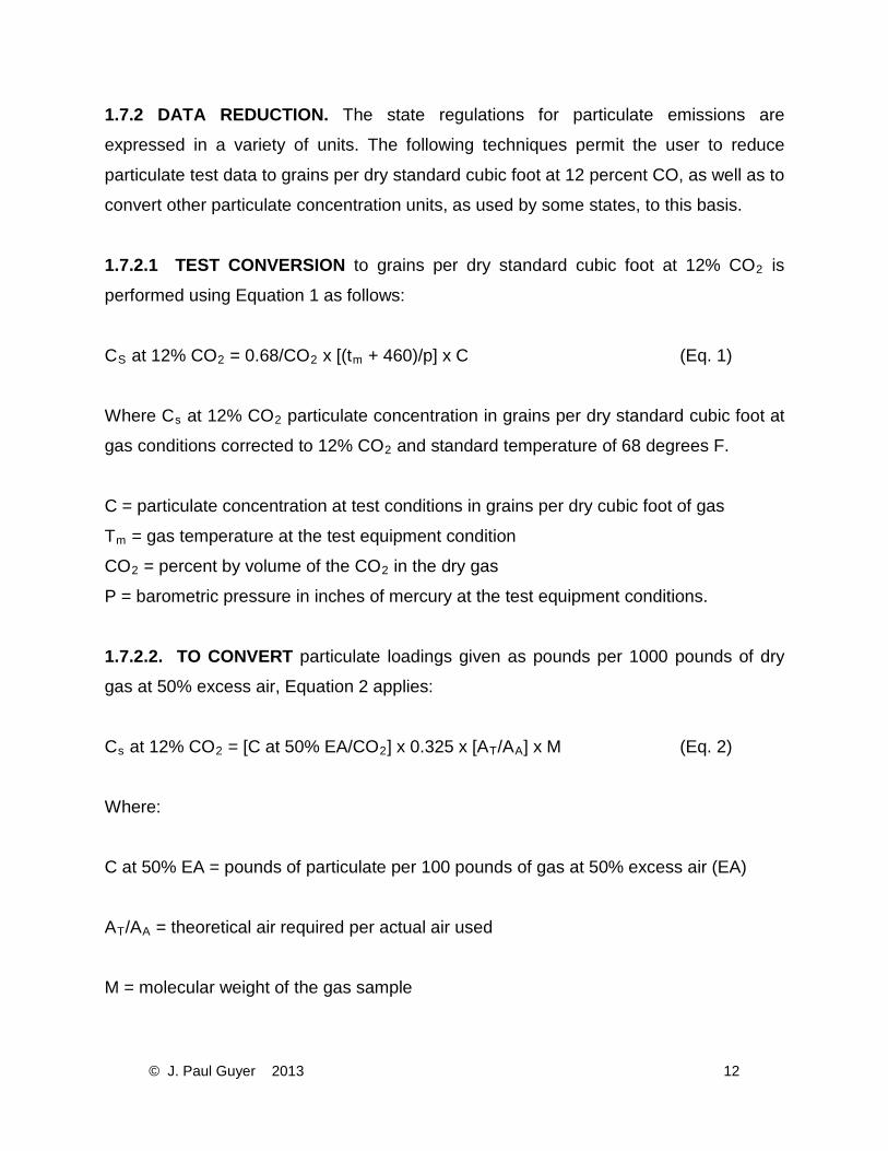
1.7.2 DATA REDUCTION. The state regulations for particulate emissions are
expressed in a variety of units. The following techniques permit the user to reduce
particulate test data to grains per dry standard cubic foot at 12 percent CO, as well as to
convert other particulate concentration units, as used by some states, to this basis.
1.7.2.1 TEST CONVERSION to grains per dry standard cubic foot at 12% CO2 is
performed using Equation 1 as follows:
CS at 12% CO2 = 0.68/CO2 x [(tm + 460)/p] x C (Eq. 1)
Where Cs at 12% CO2 particulate concentration in grains per dry standard cubic foot at
gas conditions corrected to 12% CO2 and standard temperature of 68 degrees F.
C = particulate concentration at test conditions in grains per dry cubic foot of gas
Tm = gas temperature at the test equipment condition
CO2 = percent by volume of the CO2 in the dry gas
P = barometric pressure in inches of mercury at the test equipment conditions.
1.7.2.2. TO CONVERT particulate loadings given as pounds per 1000 pounds of dry
gas at 50% excess air, Equation 2 applies:
Cs at 12% CO2 = [C at 50% EA/CO2] x 0.325 x [AT/AA] x M (Eq. 2)
Where:
C at 50% EA = pounds of particulate per 100 pounds of gas at 50% excess air (EA)
AT/AA = theoretical air required per actual air used
M = molecular weight of the gas sample
© J. Paul Guyer 2013 12
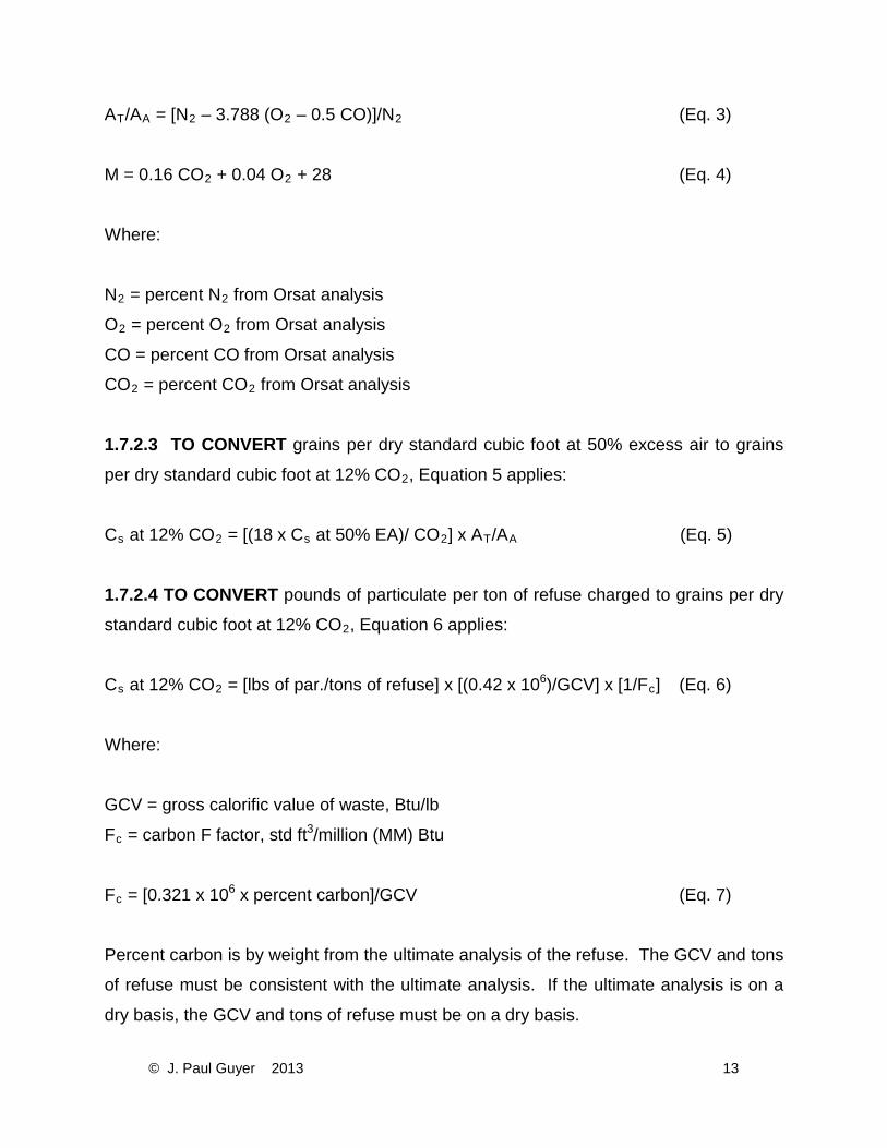
AT/AA = [N2 – 3.788 (O2 – 0.5 CO)]/N2 (Eq. 3)
M = 0.16 CO2 + 0.04 O2 + 28 (Eq. 4)
Where:
N2 = percent N2 from Orsat analysis
O2 = percent O2 from Orsat analysis
CO = percent CO from Orsat analysis
CO2 = percent CO2 from Orsat analysis
1.7.2.3 TO CONVERT grains per dry standard cubic foot at 50% excess air to grains
per dry standard cubic foot at 12% CO2, Equation 5 applies:
Cs at 12% CO2 = [(18 x Cs at 50% EA)/ CO2] x AT/AA (Eq. 5)
1.7.2.4 TO CONVERT pounds of particulate per ton of refuse charged to grains per dry
standard cubic foot at 12% CO2, Equation 6 applies:
Cs at 12% CO2 = [lbs of par./tons of refuse] x [(0.42 x 10⁶)/GCV] x [1/Fc] (Eq. 6)
Where:
GCV = gross calorific value of waste, Btu/lb
Fc = carbon F factor, std ft3/million (MM) Btu
Fc = [0.321 x 10⁶ x percent carbon]/GCV (Eq. 7)
Percent carbon is by weight from the ultimate analysis of the refuse. The GCV and tons
of refuse must be consistent with the ultimate analysis. If the ultimate analysis is on a
dry basis, the GCV and tons of refuse must be on a dry basis.
© J. Paul Guyer 2013 13
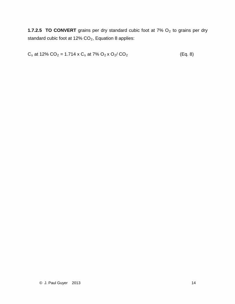
1.7.2.5 TO CONVERT grains per dry standard cubic foot at 7% O2 to grains per dry
standard cubic foot at 12% CO2, Equation 8 applies:
Cs at 12% CO2 = 1.714 x Cs at 7% O2 x O2/ CO2 (Eq. 8)
© J. Paul Guyer 2013 14
2. STACK EMISSION REGULATIONS AND THE PERMITTING PROCESS
2.1 STACK EMISSIONS. The discharge of pollutants from the smokestacks of
incinerators is regulated by both federal and state agencies. A permit to construct or
modify an emission source will almost certainly be required.
a. The emissions must comply with point source regulations, dependent upon
characteristics of the point source, and also with ambient air quality limitations which are
affected by physical characteristics of the location and the meteorology of the area of
the new source.
b. The permitting procedure requires that estimates be made of the effect of the stack
emissions on the ambient air quality. Predictive mathematical models are used for
arriving at these estimates.
c. Due to the time requirements and the complexity of the process and the highly
specialized nature of many of the tasks involved, it is advisable to engage consultants
who are practiced in the permitting procedures and requirements. This should be done
at a very early stage of planning for the project.
2.2 AIR QUALITY STANDARDS.
a. Federal Standards — Environmental Protection Agency Regulations on National
Primary and Secondary Ambient Air Quality Standards (40 CER 50).
b. State standards. Federal installations are also subject to State standards.
2.3 PERMIT ACQUISITION PROCESS.
2.3.1 NEW SOURCE REVIEW. The state agency with jurisdiction over pollution source
construction permits should be contacted at the very beginning of the project planning
© J. Paul Guyer 2013 15
process because a New Source Review (NSR) application will probably have to be filed
in addition to any other State requirements. A New Source Review is the process of
evaluating an application for a "Permit to Construct” from the Air Quality Regulatory
Agency having jurisdiction.
2.3.2 PLANNING. Consideration of air quality issues very early in the planning process
is important because engineering, siting, and financial decisions will be affected by a
New Source Review. Engineering and construction schedules should include the New
Source Review process which can take from 6 to 42 months to complete and which may
require the equivalent of one year of monitoring ambient air quality before the review
process can proceed.
2.3.3 EMISSION LEVELS. One must file for a New Source Review application if, after
use of air pollution control equipment, the new boiler or incinerator will result in
increased emissions of any pollutant greater than a specified limit. Proposed
modifications of existing boilers and incinerators that will cause increases in pollutant
emissions greater than certain threshold levels ("de minimis" emission rate) require a
New Source Review.
2.3.4 GENERAL DETERMINANTS FOR STEPS REQUIRED FOR PERMITTING. Steps required for a New Source Review depend on the location of the new source,
characteristics of the other sources in the area, discussions with the State Air Pollution
Control Agencies, possibly the EPA, and how well one is current with the changes in
regulations and administrative practices. Because of the constantly changing picture, it
is usually very beneficial to engage an air quality consultant to aid in the planning
permitting activities.
2.3.5 TECHNICAL TASKS. The principal technical tasks that are required for the
permitting effort in most cases may be summarized as follows:
© J. Paul Guyer 2013 16
(1) Engineering studies of expected emission rates and the control technology that must
be used.
(2) Mathematical modeling to determine the expected impact of the changed emission
source.
(3) Collection of air quality monitoring data required to establish actual air quality
concentrations and to aid in the analysis of air quality related values. All technical tasks
are open to public questioning and critique before the permitting process is completed.
2.3.6 NEW SOURCE REVIEW PROGRAM STEPS. The steps required in a New
Source Review vary. However, it is always required that a separate analysis be
conducted for each pollutant regulated under the Act. Different pollutants could involve
different paths for obtaining a permit, and may even involve different state and federal
agencies.
2.3.6.1 ATTAINMENT OR NONATTAINMENT AREAS. A concern which must be
addressed at the beginning of a New Source Review is whether the location is in a
"nonattainment" or “attainment” area. An area where the National Ambient Air Quality
Standards (NAAQS) are not met is a "nonattainment" area for any particular pollutant
exceeding the standards. An area where the National Ambient Air Quality Standards
(NAAQS) are being met is designated as an "attainment" area. Designation of the area
as "attaining", or "nonattaining", for each pollutant encountered determines which of the
two routes is followed to procure a permit. Note that the area can be attaining for one
pollutant and nonattaining for another pollutant. If this occurs one must use different
routes for each of the pollutants and would have to undertake both "prevention of
significant deterioration" (PSD) and "nonattainment" (NA) analyses simultaneously.
2.3.6.2 ATTAINMENT AREA. If the proposed source is in an "attainment" area, there is
a specified allowed maximum increase, or "increment", of higher air pollutant
concentrations. The upper limit of this increment may be well below the prevailing
© J. Paul Guyer 2013 17
National Ambient Air Quality Standard (NAAQS). The increment" concept is intended to
"prevent significant deterioration" of ambient air quality. The new source might be
allowed to consume some part of the “increment’‘ as determined by regulatory agency
negotiations.
2.3.6.3 NONATTAINMENT AREA. If the proposed new source is in a "nonattainment"
area, it may have to be more than off-set by decreases of emissions from existing
sources, resulting in air cleaner after addition of the new source than before it was
added. In the absence of pollutant reductions at an existing source which is within
administrative control, it may be necessary to negotiate for, and probably pay for,
emission reductions at other sources.
2.3.6.4 SUMMARY OF PERMITTING PATH. The steps listed below present a summary
of the permitting steps:
(a) Formulate a plan for obtaining a construction permit. It is usually advisable to
engage a consultant familiar with the permitting procedures to aid in obtaining the
permit.
(b) Contact state regulatory agencies.
(c) Determine if the modification could qualify for exemption from the New Source
Review process.
(d) Determine if the proposed facility will be considered a "major source" or "major
modification" as defined by the regulations.
(e) Determine if, and how, with appropriate controls, emissions can be held to less than
"de minimis" emission rates for the pollutant so the New Source Review procedures
might be avoided.
© J. Paul Guyer 2013 18
(f) Consider the questions related to prevention of significant deterioration and
nonattainment. If it is found that the facility will be a major source, determine for which
areas and pollutants you will have to follow PSD rules. Determine possible "off-sets" if
any will be required.
(g) List the tasks and steps required for a permit and estimate the costs and time
increments involved in the review process. Coordinate the New Source Review
schedule with the facility planning schedule and determine how the New Source Review
will affect construction plans, siting, budgetary impact, schedules and the engineering
for controls technology.
2.4 MATHEMATICAL MODELING.
2.4.1 MODELING REQUIREMENT. Air quality modeling is necessary to comply with
rules for proposed sources in both attaining and nonattaining areas. Modeling is a
mathematical technique for predicting pollutant concentrations in ambient air at ground
level for the specific site under varying conditions.
2.4.2 MODELING IN ATTAINMENT AREAS. Modeling is used, under PSD rules, to
show that emissions from the source will not cause ambient concentrations to exceed
either the allowable increments or the NAAQS for the pollutant under study. It may be
necessary to model the proposed new source along with others nearby to demonstrate
compliance for the one being considered.
2.4.3 MODELING IN NONATTAINMENT AREAS. Modeling is used to determine the
changes in ambient air concentrations due to the proposed new source emissions and
any off-setting decreases which can be arranged through emissions reduction of
existing sources. The modeling then verifies the net improvement in air quality which
results from subtracting the proposed off-sets from the new source emissions.
© J. Paul Guyer 2013 19
2.4.4 MONITORING. Modeling is also used to determine the need for monitoring and,
when necessary, to select monitoring sites.
2.4.5 GUIDELINE MODELS. EPA's guideline on air quality recommends several
standard models for use in regulatory applications. Selection requires evaluation of the
physical characteristics of the source and surrounding area and choice of a model that
will best simulate these characteristics mathematically. Selection of the proper model is
essential because one that greatly over-predicts may lead to unnecessary control
measures. Conversely, one that under-predicts ambient pollution concentration
requires expensive retrofit control measures. Because of the subtleties involved, it is
usually advisable to consult an expert to help select and apply the model.
2.5 MONITORING. For a New Source Review, monitoring may be required to obtain
data which shows actual baseline air quality concentrations. If monitoring is required,
prepare a monitoring plan that includes monitor siting, measurement system
specifications, and quality assurance program design. Once the plan is ready, it should
be reviewed with the relevant agencies. 2.6 PRESENTATION AND HEARINGS. After a New Source Review application is
prepared, it must be reviewed with the appropriate agency. Often a public hearing will
be necessary and the application will have to be supported with testimony. At the
hearing, all phases of work will be subject to public scrutiny and critique.
2.7 FACTORS AFFECTING STACK DESIGN.
a. Design of the stack has a significant effect on the resulting pollutant concentrations in
nearby ambient air. Stack emission dispersion analysis is used to determine increases
in local air pollution concentrations for specific emission sources. Factors which bear
upon the design of stacks include the following:
© J. Paul Guyer 2013 20
• Existing ambient pollutant concentrations in the area where the stack will be
located
• Meteorological characteristics for the area
• Topography of the surrounding area
b. Specific regulations having to do with stack design have been promulgated by the
EPA to assure that the control of air pollutant shall not be impacted by stack height that
exceeds "good engineering practice” or by any other dispersion technique. These
regulations have a direct bearing on the specific location and height of a stack designed
for a new pollution source.
© J. Paul Guyer 2013 21
3. MEASURING TECHNIQUES 3.1 CRITERIA. In order to evaluate the nature and magnitude of air pollution, establish
remedial measures and determine control programs. It is necessary to test for the
existence of pollutants. In the upgrading of existing installations, compliance is
determined through "point source emission rate tests." Revisions to the regulations regarding air pollution test requirements for federal installations appear in the Federal
Register. 3.2 STACK AND SOURCE MEASUREMENT TECHNIQUES. The point source
emission rate test methods and requirements are covered under Environmental
Protection Agency Regulations on Standards of Performance for the New Stationary
Sources, 40 CFR 60 and subsequent revisions. The techniques are listed in Table 5.
3.3 METEOROLOGICAL AND AMBIENT AIR MEASUREMENT. 3.3.1 MEASUREMENTS. Air quality measurements are used to trace emission sources
and determine if these sources comply with federal, state, and local air quality
standards. For the determination of possible violations of air quality, the continuous
monitoring of pollutant concentrations is normally required for a one-year period. Air
quality measurements are a function of the sampling site, the local meteorology, the
methods used, and the existing pollutant concentration in the atmosphere. Personnel
knowledgeable and experienced in meteorology and air quality testing are needed to
conduct and evaluate air-quality measurements.
3.3.2 SAMPLING TECHNIQUE. The criteria for instrumentation, calibration, and use of
EPA-approved sampling techniques are covered under 40 CFR 53 Environmental
Protection Agency Regulations on Ambient Air Monitoring Reference and Equivalent
Methods. See Table 6.
© J. Paul Guyer 2013 22
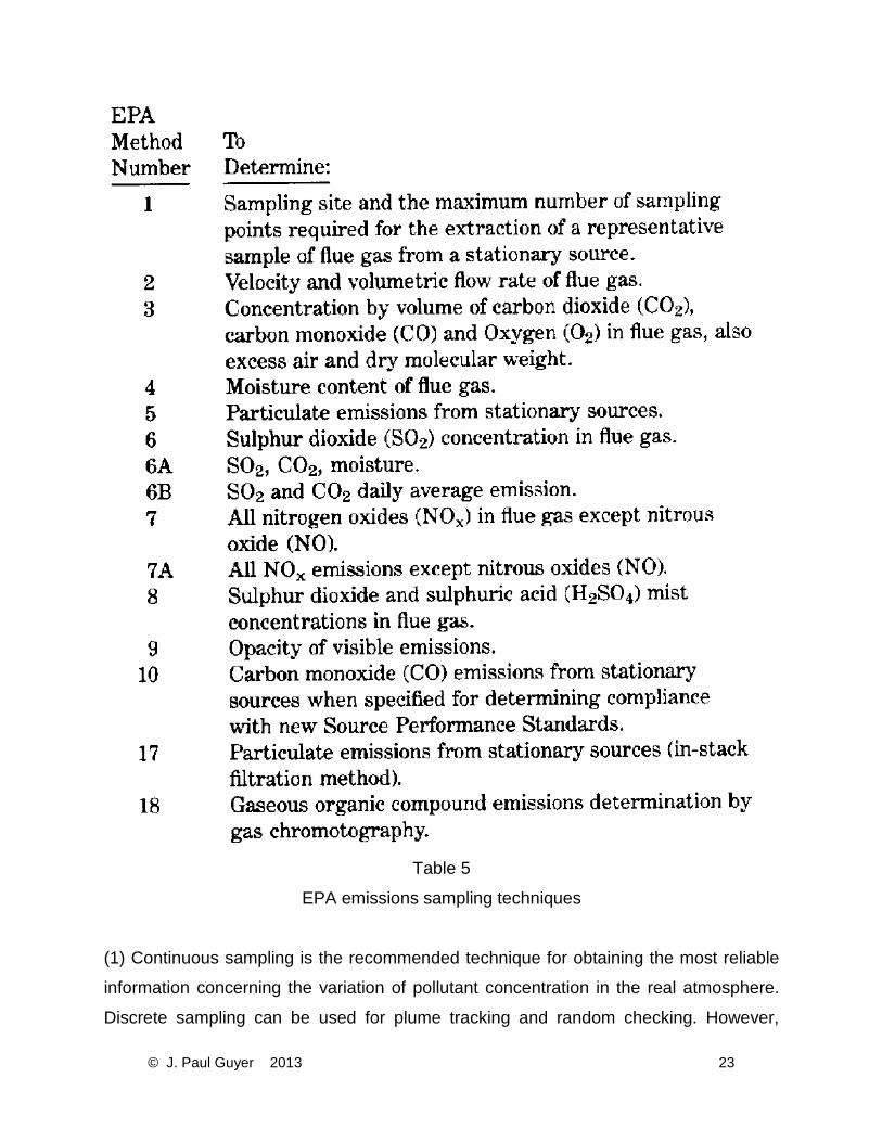
Table 5
EPA emissions sampling techniques
(1) Continuous sampling is the recommended technique for obtaining the most reliable
information concerning the variation of pollutant concentration in the real atmosphere.
Discrete sampling can be used for plume tracking and random checking. However,
© J. Paul Guyer 2013 23
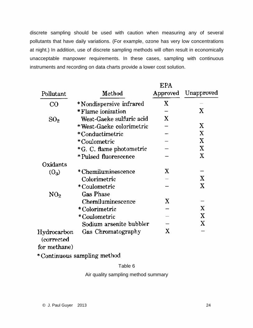
discrete sampling should be used with caution when measuring any of several
pollutants that have daily variations. (For example, ozone has very low concentrations
at night.) In addition, use of discrete sampling methods will often result in economically
unacceptable manpower requirements. In these cases, sampling with continuous
instruments and recording on data charts provide a lower cost solution.
Table 6
Air quality sampling method summary
© J. Paul Guyer 2013 24
(2) Air quality regulations require the measurement of extremely small pollutant
concentrations (1/100 of a part per million by volume). Sensitive instruments capable of
detecting small concentrations are needed.
3.3.3 SAMPLING METHOD FOR CARBON MONOXIDE. The federal reference method
for measuring carbon monoxide is the instrumental nondispersive infrared technique. A
typical instrument consists of a reference cell filled with CO free air, and a sample or
detector cell. The difference in transmittance of infrared radiation passing through the
sample cell and the reference cell is sensed by a photon detector. The difference is a
measure of the optical absorption of the CO in the sample cell and is proportional to the
CO concentration in the sample. The signal from the detector is amplified and used to
drive an output meter as a direct measure of CO concentration. This method is precise
and accurate.
3.3.4 SAMPLING METHOD FOR SULFUR DIOXIDE. The West-Gaeke sulfuric acid
method is the Federal reference method for measuring sulfur oxides. The West-Gaeke
method is a discrete bubbler technique which involves bubbling ambient air through an
impinger for 24 hours. Sulfuric acid is added to the absorber to eliminate interferences
from oxides of nitrogen. SO2 is collected in a tetrachloromercurate solution. When acid
bleach pararosaniline is added to the collected SO2 together with formaldehyde, a red
violet compound is formed which is then measured spectrophotometrically. This method
is a discrete instrumental sampling method but may be modified for continuous use.
3.3.5 SAMPLING METHOD FOR OXIDANTS AND OZONE. The instrumental-
chemiluminescence method is the federal reference method for measuring ozone. Upon
mixing ambient air and ethylene in the testing instrument, ozone reacts with the
ethylene to emit light. This light is measured by a photomultiplier. If the air and ethylene
flow rates are constant, and the proportion of air and ethylene therefore known, the
resulting signal can be related to ozone concentration. Analyzers are calibrated with a
known ozone concentration.
© J. Paul Guyer 2013 25
3.3.6 SAMPLING METHOD FOR NITROGEN DIOXIDE. The federal reference method
for NO2 is the indirect measurement of the concentration of nitrogen dioxide by
photometrically measuring the light intensity of wavelengths greater than 600
nanometers resulting from the gas phase chemiluminescent reaction of nitric oxide (NO)
with ozone (O3).
3.3.7 SAMPLING METHOD FOR TOTAL HYDROCARBONS. Gas chromatography
flame ionization is the federal reference method of measuring total hydrocarbons.
3.3.8 SAMPLING METHOD FOR PARTICULATES.
3.3.8.1 TOTAL SUSPENDED PARTICULATES. The high volume air sample is the
federal reference method for measuring total suspended particulates. Air is drawn (at 40
to 60 ft3/min) through a glass fiber filter by means of a blower, and suspended particles
having an aerodynamic diameter between 100 and 1.0 micron are collected. The
suspended particulate is calculated by dividing the net weight of the particulate by the
total air volume samples and is reported in ug/m3.
3.3.8.2 COEFFICIENT OF HAZE (C OH). A few states have standards for a particulate
measurement called the coefficient of haze. This measurement is reported in units of
COH/1000 linear feet of sampled air. In this method, air is drawn through a small spot
on a circle of filter paper until the equivalent of a 1000 feet long column of air of the
diameter of the spot has passed through the filter paper. Transmittance through this
spot then serves as a measurement of particulate material collected on the filter. There
are considerable doubts as to the usefulness and true meaning of COH data, since the
transmittance recorded is a function of the nature of the particulate as well as the total
weight sampled.
3.3.8.3 DUSTFALL (SETTLEABLE PARTICULATES). Several states have standards
for the amount of particulate that settles out of the air over a given length of time (one
common unit is grams/square meter/30 days). The method of collection is generally the
© J. Paul Guyer 2013 26
dust bucket. A dust bucket is a 15-inch deep metal or plate container with a 6-inch
opening that is exposed to the air generally for a period of one month. Dust buckets
should be partially filled with distilled water (or antifreeze) which prevents the
transporting of dust out of the buckets by strong winds. This water also acts as a wash
at analysis time. After evaporating the water, the remaining material is weighed and the
residues are converted to the required units.
3.3.9 TRACEABLE COMPOUNDS. Test methods for compounds other than those for
which standards exist are often useful in evaluating stack dispersion. If unusual fuel
additives are used, or if incinerators are used to dispose of specialized materials,
laboratory chemists can often devise sampling methods to measure these compounds
in the atmosphere.
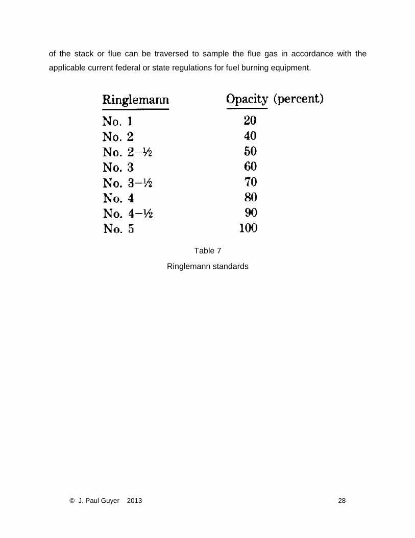
3.3.10 RINGELMANN STANDARDS. Particulate matter such as soot, fly ash, and
droplets of unburned combustibles present in exhaust gases tend to impart blackness or
opacity to a plume. It is assumed that the darker the shade of gray or black, the greater
the concentration of particulate matter present in a plume. The Ringelmann Chart offers
a set of standards with which to measure the opacity of an effluent plume. By the
comparison of the blackness of a plume to the blackness of a series of graduated light
diffusers, a Ringelmann number corresponding to a percent opacity can be assigned to
the plume (see Table 7). It should be noted that while Ringelmann numbers give a
relative indication of plume opacity, they bear no direct relationship to the plume
particulate loading. They should supplement but not replace point-source emission
tests.
3.4 FLUE GAS SAMPLING PORTS. Sampling ports are approximately 4 inches in
diameter, extend out approximately 4 inches from the stack, and have a removable
cover. On double wall stacks, sampling ports may consist of a 4-inch diameter pipe
extending from 4 inches outside the stack to the inner edge of the inner stack wall.
Accessible sampling ports shall be provided and located so that the cross sectional area
© J. Paul Guyer 2013 27
of the stack or flue can be traversed to sample the flue gas in accordance with the
applicable current federal or state regulations for fuel burning equipment.
Table 7
Ringlemann standards
© J. Paul Guyer 2013 28