Embed Size (px)
Citation preview

A Case Study on Laying of 132 kV
Underground cables in LMRC
By:
Mahendra Kumar
Director / Rolling Stock and Systems
14.10.2017

• Lucknow, the capital of Uttar Pradesh is the principaladministrative, commercial and distribution centre of the state
• Population of Lucknow is increasing at significantly faster rate:
• Lucknow Metro Rail Corporation has been set-up as a 50:50 jointlyowned Company of Govrnment of India and the State Governmentfor planning, implementation and operation of Lucknow Metroproject.
• Apart from Equity contribution by the two Governments, project isbeing funded by soft loan from European Investment Bank (EIB)and contribution by local bodies.
Population as per 2011 Census 2.9 Million
Projected Population in 2031 4.8 Million

Metro Rail Alignment
Corridors DescriptionElevated
(km)Underground
(km)
Total Length(km)
North – South Corridor(CCS Airport toMunshi Pulia)
19.438 3.440 22.878
No. of Stations 18 4 22
Two Metro corridors for Lucknow namely N-S corridor and E-W corridor
have been identified with total length of 34km. Initially implementation of
22.878Km partly elevated and partly undergrond N-S corridor is being
undertaken
Physical construction on Priority Section of 8.5 km from Transport Nagar toCharbagh commenced on 27th Sep, 2014 .
Majority of Govt. land for priority section already transferred to LMRC byGovt. of UP free of cost / long term lease including land for the Depot.
Private land acquisition arranged through direct negotiation. All the System Contracts like Rolling Stock and Signalling, Traction, Telecom,
Depot, Track, AFC etc. awarded for the entire corridor. Works in progress. General Consultants are in position for technical guidance. Work commenced on Priority Section from Transport Nagar to Charbagh
(8.5 km) on 27.09.2014. Work completed in a record less then 3 years timeperiod. Commercial operation started on 06.09.2017.
Work in rest of the U/G and Elevated section is under progress as perschedule.
Target Date of completion of N-S Corridor – April, 2019. Progress – Physical – 50 %
Financial – 48%
Status of Project Implementation
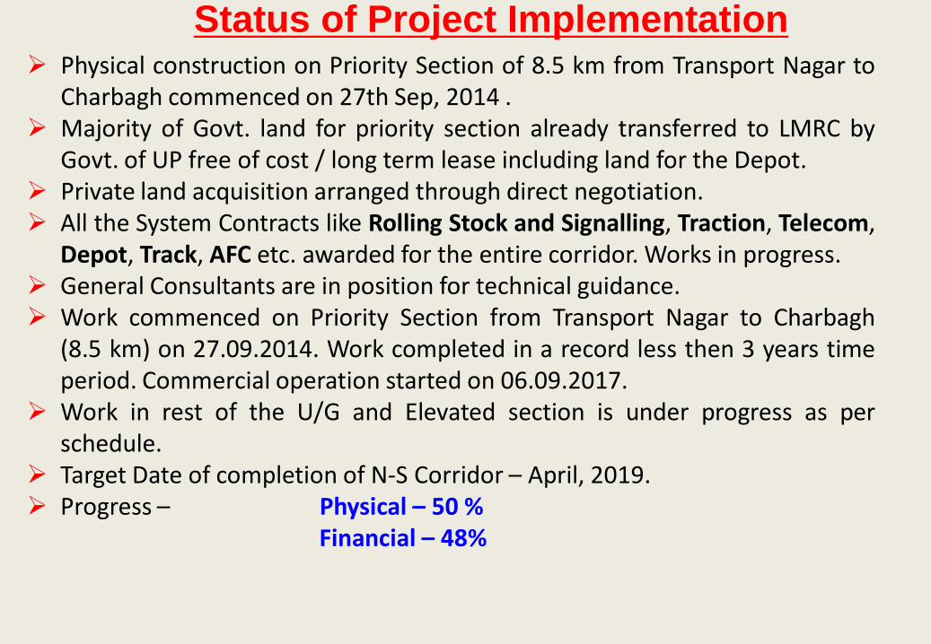
Physical Progress (Priority Section) : 98 %
Physical Progress (N-S Corridor) : 49 %
Financial Progress (N-S Corridor) : 47 %
Status of Project Implementation
General Consultants: Consortium of Ayesha-KRNA-Geodata-Aarvee
appointed for technical guidance and project management support.
Civil and E&M works for Under Ground section in progress.
Civil Construction for balance Elevated portion also commenced.
Target date for completion of entire Phase-1A project – March, 2019.

Metro being constructed with frontline technologies
•Standard Gauge (1435 mm) with 25KV Overhead Traction
•State-of-art modern light weight Stainless Steel Rolling Stock
•Ballastless Track with high speed canted turnouts
•Communication Based Train Control (CBTC) Signalling system
•Heavy Duty Escalators and Passenger Heavy Duty Lifts
•Energy Efficient Electrical & Mechanical systems with Combination of air cooled
and water cooled chillers for Air- conditioning System, LED lights, Silent DG sets,
Fire detection and suppression system etc.
•Contactless AFC system using Smart card/Tokens, TVMs
•Advanced Telecommunication system using the state of the art PA,PIDS ,
Announcement system, CCTV system
•Design Speed: 90 Kmph, Average Speed: 32-34 Kmph
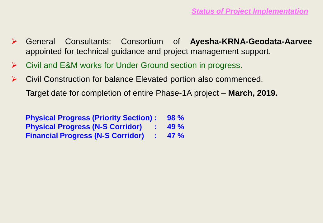
15.43
15.43
6.91
4.573.77
53.89
Equity By GOI (15.43%)
Equity By GUP(15.43%)
SD for CT by GUP(6.91%)
SD for CT by GOI(4.57%)
Grant from Local Bodies(3.77%)
1.40% JICA Loan /12% Market Borrowings(53.89%)External Soft Loan (52.89%)
European Investment Bank (EIB) has committed to fund Euro 450 Million soft loan for the Project

8
• Civil and E&M works for Under Ground section from Charbagh to K.D. Singh Babu
Stadium in progress through M/s Gulermak-TPL JV .
Diaphragm wall construction for all the three stations in progress viz. Hussain
Ganj, Sachivala and Hazaratganj.
First TBM commenced work on 23.01.2017 about one month ahead of
schedule. Second TBM also commenced work on 28.02.2017 and initial drive
in progress.
Tunnel Segment casting in progress at casting yard.
200 m tunnelling completed in UP Line.
• Civil works for elevated section (LKCC-07) beyond K.D. Singh Babu Stadium to
Munshipulia in progress through M/s L&T.
11 piling rigs moblised and 260 piles and 11 pile cap casted
Casting yard set up. 7 pier caps and 6 U-girders casted
• Tender for construction of Underground Station at Airport has been invited after
obtaining ‘’No Objection’’ from EIB and due for submission on 22th March 2017.
Balance Section Works

SUSTAINABLITY PLANNING IN LUCKNOW METRO• Energy Conservation and Energy efficient equipments
- Regenerative Braking in the trains – 30%-35% saving in the tractionenergy thereby reduction in emission of GHG
- Regenerative Braking in Lifts
• Sustainability and Environment friendly Technology being given dueimportance -LED lights at stations
• Water management - mixed use of water cooled and air cooled chillers for the UG stations.
• Renewable Energy Sources being given due priority –roof mounted solar panels on large buildings in the Depot and at staions.
• Green Initiative - All the stations in the process for getting the Certifications (Gold/Platinum) as per IGBC Rating
System designed to be Barrier Free for physically challenged and Senior Citizens

Substation and Cabling works
• Two Receiving Substations
132kV/33kV/25kV – 2 ckts of about 6km route length (Total 36 kms of cables)
220kV/33kV/25kV – 2 ckts of about 10 km route length (Total 60 kms of cables)

INTRODUCTION TO LUCKNOW
METRO 132KV CABLE LAYING
WORK
RSS and 132kV CABLE LAYING
Transport Nagar RSS-
• The RSS receives power at 132kV through double circuit underground cables laidfrom 400/220/132KV Grid Substation of UPPTCL at Sarojini Nagar which is fedthrough a number of sources at 400kV, 220kV and 132kV level. Six kilometers ofdouble circuit of 132kV EHV cables are laid between the Sarojini Nagar Grid SubStation to Transport Nagar Receiving Sub Station of LMRC. One circuit isadequate enough to meet entire load. 100% Redundancy has been providedthrough the second circuit to improve the reliability.
• The physical work of 132kV Cable laying works started on 25 April 2016 and thecables were energized on 06 th October 2017. The work has been completed in arecord time of nearly 6 months. The substation was energized in about 9 months.

Redundancy at UPPTCL Grid Substation

132kV EHV Cable Route From Transport Nagar RSS to Sarojini Nagar Substation

Modes of Cable Laying
Laying by open trench method
• Trench Dimension is 1.5mX1.8m
• Double circuit, Trefoil formation.
• Each circuit consisting of 3 single core cables for R, Y and B phase respectively.

Modes of Cable Laying(Open Trench cross sectional details)

Modes of Cable Laying Cable Laying by Trenchless (HDD)
method• Horizontal Directional Drilling (HDD) is done
as per site conditions where cable laying byopen cut method of trench is not possible.
• 3 Nos, 400mm dia holes were drilled usingHDD machines.
• Total 10 no. of HDPE pipes (6 nos. of 200mm dia pipes for circuit-1 & 2 cables, 2 nos.of 200mm dia Spare pipes and 2 nos. of40mm dia pipe for OFC cable)
• Through each pipe only one single corecable is laid.

Modes of Cable Laying - HDD

Modes of Cable Laying(HDD cross sectional trench details)

Modes of Cable Laying
Laying through pipes-
• At places like front area of main gates ofbuildings, houses, shops etc. this method ofcable laying was adopted.
• HDPE pipes are buried by open cut methodand immediately after laying the pipe of shortlength (8-12m), area is backfilled.
• Helpful in places to avoid stoppage ofcommuters movement due to cable layingworks.

132kV Cable Joint Bay Detail

Challenges faced in 132kV Cable Laying
• 132kV cable is crossing 8” Mourawan-Lucknow Gas pipeline of GAIL (CNG transmissionpipeline) at one location(Gauri Market, near Sainik School) in the cable route. So far therewas no Standard available for laying cables beyond 66kV crossing the gas pipeline of thisnature. This had to be developed in consultation with the GAIL authorities.
• Special mitigation measures were jointly worked out by LMRC and GAIL. Initially it wasplanned to cross the gas pipeline by keeping 1.5 meters vertical gap with 80mm thickConcrete slab in between as per GAIL’s instruction.
• For going 1.5M deep below gas pipeline, the cables had to be laid at 3M depth fromground level. Since the area belonged to dense market place therefore it wouldn’t havebeen safe to open cut pits of depth of 3m, therefore it was not feasible to lay the cablesby direct buried method at such depth. So LMRC laid the cables by trenchless method at 8meter depth (more safety margin)from the ground level which was accepted by GAIL.

GAIL Pipe Line Crossing Details

Challenges Faced in Nagar Nigam Road
• Route Length of Nagar Nigam road (BetweenNH-25 to UPPTCL Substation road) was approx.500 m and width of road was 5m.
• Top Layer of road consist of 200mm thick RCClayer for movement of heavy trailers to SarojiniNagar Substation and it was the onlyconnecting road of S/s to main road (NH-25).
• Under ground live/ charged utilities consistingof 33kV, 11kV were also present below theroute so HDD could not been done.
• For making cable trench, first 200mm RCC toplayer was crushed by Electrical Hammer. Then500 mm depth digging was done by JCB(including top layer of 200 mm).

Challenges Faced in Nagar Nigam Road• Next 800mm depth digging was done manually
to avoid any untoward situation due to near bycharged under ground utilities, domestictelephone line , pipe line etc. Further, to allowmovement of commuters backfilling were alsoprocessed as soon as 12 m pipe were laid intrench.
• At one point, 33kV Charged Cable feeding toNadarganj Station were to be crossed by LMRC132kV Cable for which 20 min shut down timewas only given and the task was completedwithin the stipulated time.
• Finally, cables were laid in trenches ofdimension 800mmX1.3 m through 8 Nos HDDpipe of 200mm dia (3 each for circuit 1 & 2, twospare pipes ).and 2 nos. of 40mm dia HDPEpipes for OFC.

Challenges faced in Jointing Bay(JB) No 6 Location
• Before JB-06 location there was a NagarNigam concrete drain of dimension of 1.5mX3m.
• Drain was live and crossing the road at 90degree.
• Since the drain was just before the JB-06location therefore HDD (trenchless) was notdone to keep the Joint Bay at requireddepth.
• Specialized agency had done the drills/holesof 250mm dia in the drain wall to crossthrough the drain channel. Then the cableswere laid in 200mm dia HDPE pipe throughthe drain.

Challenges faced during rains
• Heavy Rain causes frequent fillingof open trenches with water .
• Rain water from the trenches weredrained out using 5 Hp submersiblepumps to drain out 4000 ltr ofwater in 5 Minutes.
• Jointing bays were completelysealed using tarpaulin to avoidingress of moisture inside thejointing cabinet/room.

Challenges faced due to untoward/unwanted situation
• An speedy bus hit the standing truck nearcable laying site which further hit theLMRC barricading. Due to collapse ofbarricading on cables, outer sheath andinsulation of circuit-1, B phase cable wasdamaged. The cable was repaired byproviding a Joint.
• Separate Jointing Bay was made forJointing.
• Due to proper Barricading of the trenchrest of the cables remained safe.

Selection of cables
• Conductor X-section: Based on the requirement of power transmission
Aluminium conductor of 630 sqmm. cross section is used for 132 kV Cable from
Transport Nagar RSS to Sarojini Nagar Substation.

Selection of cable route
• The main consideration for the selection of cable route were as below:
a. Shortest possible route.
b. Cable route were selected preferably along the main carriage way for easy access
of men and material for installation as well as during maintenance.
c. Cable route through Private lands was avoided.
d. Water logging areas were avoided.
e. Availability of proper space was ensured for Jointing locations.
f. Availability of required clearance from existing underground utilities in the route are
also ensured.
• In Phase IA of North South Corridor cable laying was a part of Traction and
Auxilary Power Supply Contract(LKE1&2).
Utilities involved in cable route
• The major utilities in the 132kV Cable Route were NHAI, UPPWD, GAIL,UP
Forest Dept., GGL, Nagar Nigam, BSNL, Powergrid , UPPCL(LESA) and
UPPTCL.
• The ROW permission from all the major utilities were obtained with in two
months times and no hindrance had been faced by LMRC during Cable laying
works from the utilities.
• Restoration/Rectification charges wherever required was submitted in form of
Demand Draft and Bank Guarantee to the respective utilities as per their terms
and conditions. In case of road restoration by LMRC, after completion of the
cable laying work the route was restored to its original form upto the
satisfaction of authorities.
In Plant Testing
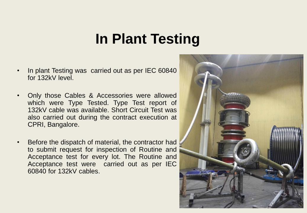
• In plant Testing was carried out as per IEC 60840for 132kV level.
• Only those Cables & Accessories were allowedwhich were Type Tested. Type Test report of132kV cable was available. Short Circuit Test wasalso carried out during the contract execution atCPRI, Bangalore.
• Before the dispatch of material, the contractor hadto submit request for inspection of Routine andAcceptance test for every lot. The Routine andAcceptance test were carried out as per IEC60840 for 132kV cables.
Cable Laying
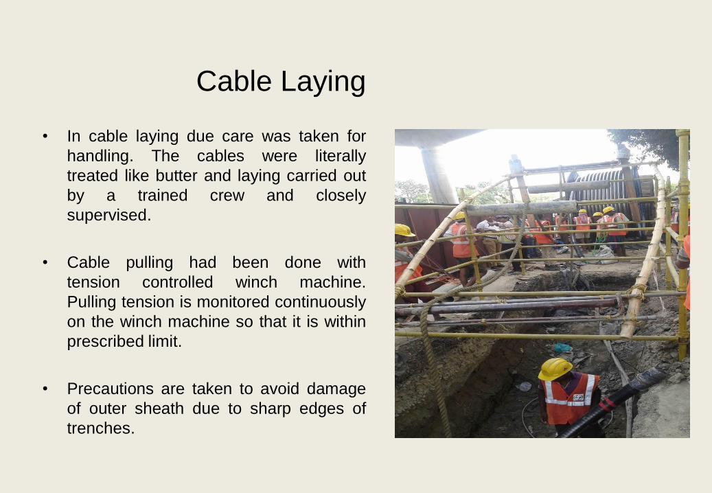
• In cable laying due care was taken for
handling. The cables were literally
treated like butter and laying carried out
by a trained crew and closely
supervised.
• Cable pulling had been done with
tension controlled winch machine.
Pulling tension is monitored continuously
on the winch machine so that it is within
prescribed limit.
• Precautions are taken to avoid damage
of outer sheath due to sharp edges of
trenches.

Cable Laying• Scaffolding and the guide rollers from the drum to the trench were placed. The
scaffolding and the guide rollers were arranged to keep the allowable cablebending radius so as to prevent the cable from being damaged by severe bending.
• Rollers were placed at every 2-3 meters along the straight portion and at shorterintervals along the curved portion of the trench.
• Vertical rollers were also used to keep the allowable radius, and also set firmlyagainst the wall for lateral pressure caused by the pulling tension.
• Reliable communication between manpower near the drum, the head of the teamand the winch machine was ensured to coordinate the work satisfactorily.

Joints and Terminations
• Jointing of cables were done in a Joint Baymade of brick wall and RCC base. Pre-mouldedstraight through type Joints have been used for132kV cables.
• Jointing & Termination had been done byqualified and experienced persons in clean andAir conditioned environment. A cabinet ofproper size was installed at the jointing baylocation. A water pump was also kept nearJointing Bay to deal with any exigency if therain is started.
• Oil Filled outdoor type termination for cabletermination at LMRC bay in PSA Substation.
• Dry type terminations were used for cabletermination at LMRC GIS end.

132KV Termination at Grid Substation

Earthing and Bonding of Cable Sheath
• Single core cables have been used in LMRC for high voltage transmission system which iscovered with a Corrugated Aluminum metallic sheath for the following requirements
i. To prevent ingress of moisture
ii. To protect the core from the mechanical damage
iii. To create earthed shield
• Unlike three core cables, whenever current is passed, it starts behaving like a single-phasestep down, transformer. The conductor acts as primary winding and metallic sheath ofthe cable acts as secondary winding. The magnetic flux generated by the current flowingthrough the conductor induces an e.m.f. in the metallic cable sheath.

• In the cable sheath, a voltage is induced as a function of the operating current. In order tohandle this induced voltage, both cable ends have to be bonded sufficiently to theearthing system. As per the calculation made for induced sheath voltage, Cross bondinghas been adopted for 132kV U/G LMRC cable system.
• In Cross Bonding, sheaths are electrically transposed at every straight through jointlocations and sheath voltage limiters (SVL) are required to be provided at 2 out of 3 jointlocations. In cross bonding design the total route length of the cable is sub divided intosmaller sections of the cable lengths each and Terminations are solidly earthed.

Cross bonding arrangement for 132kV Cables

Sheath Voltage Limiter (SVL)
Sheath Voltage Limiters were installed to limit
the high voltages produced in the cable
sheaths at the time of fault in the cable. In
normal condition the voltages induced in the
cable sheaths are not allowed to increase
beyond 65 volts with the help of cross bonding
and single point bonding of cable sheaths. The
cross bonded sheaths are connected to the
grounding system through sheath voltage
limiters such that the cross bonded sheaths
are floating during normal operation of cables
and at the time of faults, when the sheath
voltages rise abruptly, the SVL acts as a short
between the cable sheath and earth, hence
cable sheath is grounded directly.
Cross bonding has been done in LMRC 132kV
Cables and is working satisfactorily.
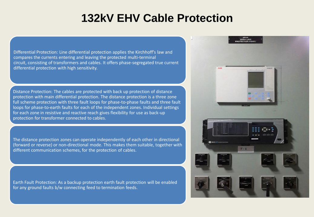
132kV EHV Cable Protection
Differential Protection: Line differential protection applies the Kirchhoff's law and compares the currents entering and leaving the protected multi-terminal circuit, consisting of transformers and cables. It offers phase-segregated true current differential protection with high sensitivity.
Distance Protection: The cables are protected with back up protection of distance protection with main differential protection. The distance protection is a three zone full scheme protection with three fault loops for phase-to-phase faults and three fault loops for phase-to-earth faults for each of the independent zones. Individual settings for each zone in resistive and reactive reach gives flexibility for use as back-up protection for transformer connected to cables.
The distance protection zones can operate independently of each other in directional (forward or reverse) or non-directional mode. This makes them suitable, together with different communication schemes, for the protection of cables.
Earth Fault Protection: As a backup protection earth fault protection will be enabled for any ground faults b/w connecting feed to termination feeds.

Safety at Site• The Cable laying work is done in public area
along the main road and running traffic. Utmost
care is taken on safety to avoid any accident.
Safety at site is followed as per LMRC SHE
Document (Conditions of contract on
safety, health and Environment, Volume 6).
• Before the excavation for trenches, the area is
properly barricaded with hording boards and
secured from outside excess.
• Hording board used for barricading are properly
fastened to the ground.
• Every personnel at site was well equipped with
proper PPE’s to ensure utmost safety at working
site.

Commissioning Tests
During the installation of cables, DC voltage test on cable sheath was done oneach length of cable to find out any damage to the outer sheath of cable.
After the installation, Continuity test and conductor resistance test is done.
High Voltage AC test is carried before regular energisation as per IEC 62067 &IEC 60840. Insulation resistance is measured before and after the high voltage ACtest.
High voltage test is carried out by keeping the cable energised at rated voltage for24 hours by taking supply from Grid Substations. However before charging thecables from Grid, Cables are tested with High voltage, Very low frequency (VLF)test kit to ensure the healthiness of cables.
Before the energization of cables, clearance was taken from Electrical Inspector toGovernment of India (EIG).
THANK YOU
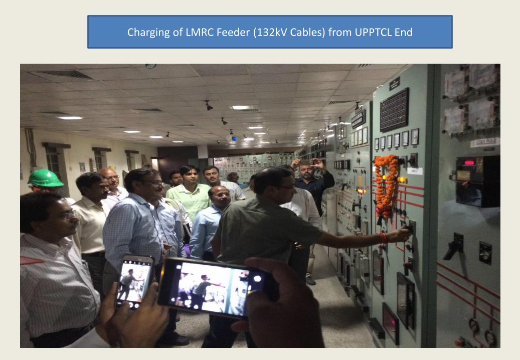
Charging of LMRC Feeder (132kV Cables) from UPPTCL End
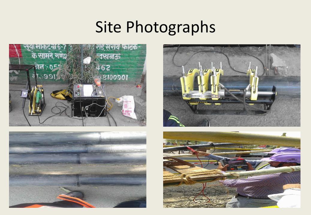
Site Photographs

Site Photographs

Site Photographs

THANK YOU


![Young - Structural Design And Laying Of Underground Drains [DOT 1984].pdf](https://img.dokumen.tips/doc/110x75/577c778f1a28abe0548c96bc/young-structural-design-and-laying-of-underground-drains-dot-1984pdf.jpg)