Embed Size (px)
Citation preview

A C C U D R I V E
SERIES RG

CustomizationHigh preciand accu
Cone Drive is a world leader in precision motion control technology. We work with our customers every step of the way – from design
specs to the final solution – to create highly precise, highly specific products that keep our customers’ technology at the forefront of their industry. Cone Drive offers engineering support, unique solutions, and
innovative technology across a breadth of markets and products to drive your company forward.

PRODUCT RANGE 4
ACCUDRIVE PRECISION PRODUCTS 5
ONLINE CONFIGURATOR 6
SERIES RG DESIGN FEATURES 8
SERVO UNIT DESIGNATIONS 12
MOTOR MOUNTING CODES 13
STANDARD HOLLOW SHAFT DIMENSIONS 14
SOLID SHAFT DIMENSIONS 15
OPTIONAL OUPUT DIMENSIONS 16
NEMA UNIT DESIGNATIONS 18
REDUCER HOLLOW SHAFT DIMENSIONS 19
NEMA HOLLOW SHAFT DIMENSIONS 20
NEMA FRAME SPECIFIC DIMENSIONS 21
NEMA DOUBLE REDUCTION 22
GENERAL SPECIFICATIONS 24
RATINGS 27
PRODUCT SELECTION TOOL 42
INSTALLATION, OPERATION & MAINTENANCE INSTRUCTION 44
PRODUCT SAFETY 45
TABLE OF CONTENTS A C C U D R I V E S E R I E S R G

4 | ACCUDRIVE SERIES RG SALES: 1-888-994-2663 SALES FAX: 1-888-907-2663 TRAVERSE CITY, MI CONEDRIVE.COM
Serving an entire spectrum of mechanical drive applications from food, energy, mining and metal; to automotive, aerospace and marine propulsion, we are your source for drive solutions.
We can create custom engineered transmission solutions of any size and configuration.
SERIES HPWorm gearbox with double-enveloping worm gearing. Available in single, double and triple reductions
SERIES WPrecision right angle servo gearbox
SERIES HP-AUniversal metric housing featuring double-enveloping gearing & drywell feature
SERIES SValue engineered right angle servo gearbox
DUO DRIVEDual gears on parallel output shafts
SERIES RGModerate precision right angle servo gearbox
SERIES BIndustrial duty worm gearbox featuring Conex gearing
SERIES LE / PIn-line helical geared motors & reducers and precision planetary servo gearbox
HARMONICCone Drive Harmonic Solutions® offer the ultimate in precision motion control technology
SLEWING SOLUTIONSVersatile slew bearings and slew drives featuring external, internal and without teeth options in a low profile, ready-to-install package
STAINLESSRight angle, IP-69K rated for the food processing market
DOUBLE-ENVELOPING WORM GEAR SETAvailable in standard sizes, ratios and backlash options along with custom worm gear sets
STAINLESS SERVOSmooth, contoured stainless steel housing (316), IP69K rated right angle gearbox
HP SERVOThis double-enveloping worm gearing, high torque gearbox meets the most demanding needs as servo motor capacities increase
INDUSTRIAL SOLUTIONS PRECISION MOTION SOLUTIONS
Product Range

CONE DRIVE | 5SALES: 1-888-994-2663 SALES FAX: 1-888-907-2663 TRAVERSE CITY, MI CONEDRIVE.COM
Design flexibility and lasting performance with our complete family of AccuDrive Precision Products.
SERIES W RIGHT ANGLE GEARHEAD• Output torque capacity up to 10,000 lb.in. (1,130 Nm)• Solid shaft and Servo motor interfaces standard
(NEMA and IEC available upon request)• Center distance 38 to 89 mm• IP65 rated• Input speeds up to 6,000rpm• Sizes available 38, 51, 64, 76, and 89• Universal mounting• Gear ratios from 5:1 to 60:1
SERIES S SERVO GEARHEAD• Economical servo solution• Output torque up to 7,540 lb.in. (852 Nm)• Motor adapters to fit servo motors• Center distance from 1.33 inch up to 3.54 inch• Speed range up to 4,000 RPM• Flexible mounting (hollow output standard with plug in solid shaft)• Ratios from 5:1 to 60:1
SERIES P IN-LINE PLANETARY SERVO GEARHEAD• Output torque capacity up to 21,240 lb.in. (2,400 Nm)• Speed range up to 6,000 RPM input• Sizes available 42, 60, 90, 120, 140, 180, 220 (S-Type)• Sizes available 60, 75, 100, 140, 180, 210, 240 (P-Type)• Gear ratios from 3:1 to 100:1 available from stock (S-Type & P-Type)• Universal Mounting with shaft mount and flange mount standard• 3 arc-minutes backlash or better
SERIES LE IN-LINE PLANETARY SERVO GEARHEAD• Output torque capacity up to 7,080 lb.in. (800 Nm)• Speed range up to 6,000 RPM input• Sizes 40, 60, 90, 115, 512 and 160 (Series E)• Gear ratios from 3:1 to 64:1 (Series E)• Sizes 50, 70, 90, 120, 155, 205, 235 (Series LE)• Gear ratios from 3:1 to 100:1 (Series LE)• Universal Mounting with shaft mount and flange mount standard• Backlash as low as 8 arc-minutes (Series E) and 5 arc-minutes (Series LE)
ABSOLUTE ZERO BACKLASH ACCUDRIVE GEARING• Unique design captures both sides of the gear tooth to
completely eliminate backlash. Automatically compensates for wear-guaranteed zero backlash for the life of the gear. Available for single, double and triple reduction types, gear sets, special designs and the Series W.
AccuDrive Precision Products

6 | ACCUDRIVE SERIES RG
Our AccuMate® program helps you select the right servo gearhead for your application.
Configure Your AccuDrive Onlinewww.ConeTools.com
Visit ConeTools.com and Click
“AccuDrive - RG Servo”
1

CONE DRIVE | 7SALES: 1-888-994-2663 SALES FAX: 1-888-907-2663 TRAVERSE CITY, MI CONEDRIVE.COM
Build your unit by selecting criteria specific to your needs
3
CONE DRIVE | 7
Online Configurator
Start configuring your AccuDrive product by selecting Series RG or entering in the direct code in the entry box
2
On the final screen review the product specifications and click to create a CAD file, download the specs or request a quote
4
8 | ACCUDRIVE SERIES RG SALES: 1-888-994-2663 SALES FAX: 1-888-907-2663 TRAVERSE CITY, MI CONEDRIVE.COM
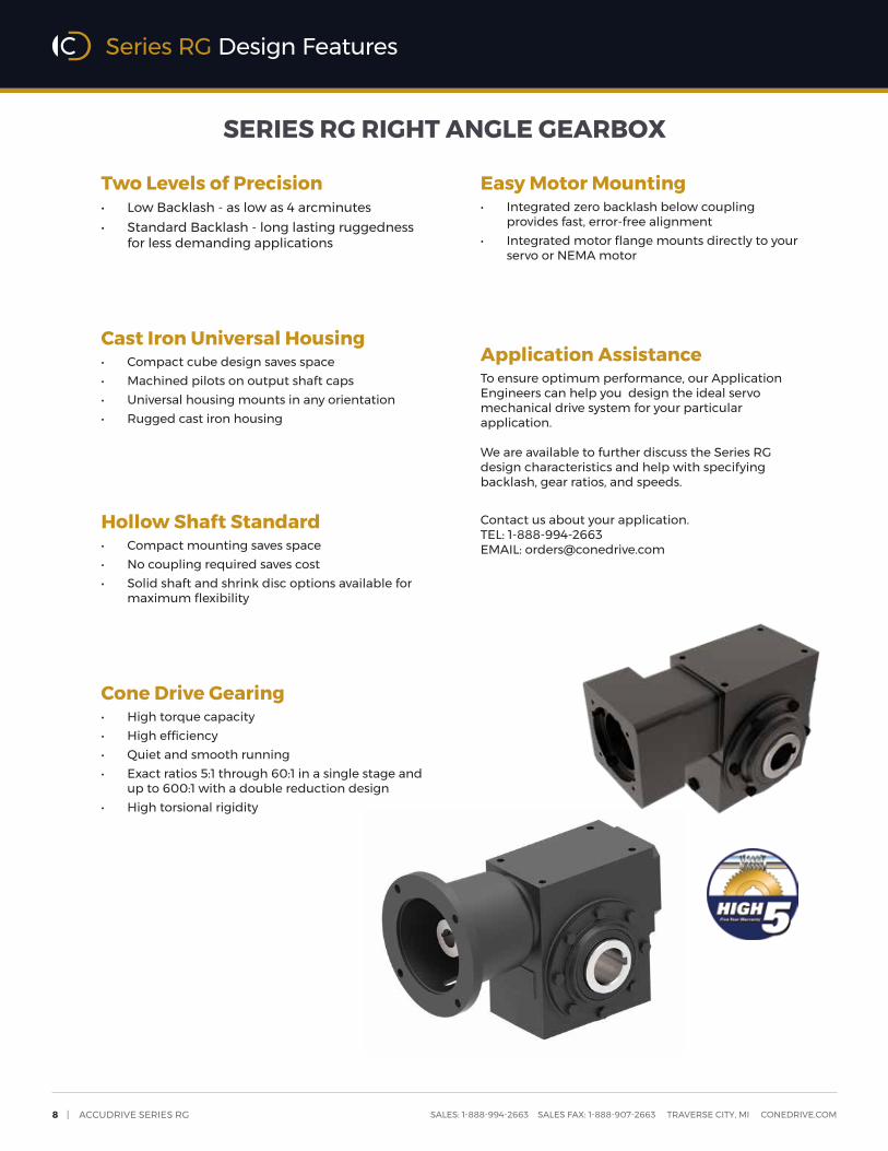
Two Levels of Precision• Low Backlash - as low as 4 arcminutes• Standard Backlash - long lasting ruggedness
for less demanding applications
Cast Iron Universal Housing• Compact cube design saves space• Machined pilots on output shaft caps• Universal housing mounts in any orientation• Rugged cast iron housing
Hollow Shaft Standard• Compact mounting saves space• No coupling required saves cost• Solid shaft and shrink disc options available for
maximum flexibility
Cone Drive Gearing• High torque capacity• High efficiency• Quiet and smooth running• Exact ratios 5:1 through 60:1 in a single stage and
up to 600:1 with a double reduction design• High torsional rigidity
Easy Motor Mounting• Integrated zero backlash below coupling
provides fast, error-free alignment• Integrated motor flange mounts directly to your
servo or NEMA motor
Application AssistanceTo ensure optimum performance, our Application Engineers can help you design the ideal servo mechanical drive system for your particular application.
We are available to further discuss the Series RG design characteristics and help with specifying backlash, gear ratios, and speeds.
Contact us about your application.TEL: 1-888-994-2663 EMAIL: [email protected]
Series RG Design Features
SERIES RG RIGHT ANGLE GEARBOX

CONE DRIVE | 9SALES: 1-888-994-2663 SALES FAX: 1-888-907-2663 TRAVERSE CITY, MI CONEDRIVE.COM
SERIES RG RIGHT ANGLE GEARBOX
HIGH PRECISION RIGHT ANGLE DRIVE The Series RG right angle drive offers an affordable solution for your
motion control applications. Packaged in a compact cast iron housing, the Series RG has high torsional rigidity, is quiet, smooth running, and is capable of
operating at input speeds of up to 4,000 RPM.
Rugged performer.The Accudrive Series RG is a compact right angle precision drive that provides an economical solution for your general automation applications. Built around the Cone Drive double-enveloping worm technology, the Accudrive Series RG is available in standard and low backlash options.
Sizes (Center Distance-in): 1.5, 2.0, 2.5, 3.0, 3.5
Standard Reduction Stages: Single, Double
Interface: Inch or metric
Output Torque: Up to 7,800 lb.in. (880 Nm)
Gear Ratios: 5:1 to 60:1; custom ratios available
Ingress Protection: IP65 (Servo Version)
Input Options: Solid shaft, NEMA + Servo motor interfaces
Output Shaft Options: Solid, Hollow, Shrink Disc
Backlash Options: Standard, Low
Mounting Options: Universal mount, Output flange
PRODUCT FEATURES
S P E C I F I C A T I O N S
Series RG Specifications

10 | ACCUDRIVE SERIES RG SALES: 1-888-994-2663 SALES FAX: 1-888-907-2663 TRAVERSE CITY, MI CONEDRIVE.COM
PACKAGING | FOOD & BEVERAGE | SATELLITE COMMUNICATION | PHARMACEUTICAL | AUTOMATION
Series RG Applications

CONE DRIVE | 11SALES: 1-888-994-2663 SALES FAX: 1-888-907-2663 TRAVERSE CITY, MI CONEDRIVE.COM
S E R I E S R G
Servo Specific Information
PACKAGING | FOOD & BEVERAGE | SATELLITE COMMUNICATION | PHARMACEUTICAL | AUTOMATION

12 | ACCUDRIVE SERIES RG SALES: 1-888-994-2663 SALES FAX: 1-888-907-2663 TRAVERSE CITY, MI CONEDRIVE.COM
S
K
Servo
Unit with adapter to fit servo motor & keyed coupling
1
3-4 SIZE OF UNIT
5 REVISION
15-19 MOTOR MOUNTING See page 13
R G 3 0 1 0 1 5 S S N D 0 2 C D F K D -
1 2 3 4 5 6 7 8 9 10 11 12 13 14 15 16 17 18 19 20
20 SPECIAL FEATURES
- NoneS Stainless Steel PaintW White Epoxy PaintZ Misc special features (specify)
12 INPUT SPEED
11 OUTPUT SHAFT
Single Extended input:(in worm over position)
Double Extended input:(in worm over position)
13-14 ASSEMBLY POSITION
1 52 02 53 03 5
6-8 RATIO
1-2 SERIES G
10 TYPE OF UNIT
S
L
Standard Backlash
Low Backlash
9 UNIT VERSION
R
5 . 01 0 .1 5 .2 0 .
5 . 06 . 07 . 08 . 09 . 01 0 .1 5 .
2 0 .2 5 .3 0 .4 0 .5 0 .6 0 .
3 0 .4 0 .5 0 .6 0 .
Size 15
Size 20 - 35
A Inch hollow outputC Metric single extended solid outputD Metric double extended solid outputH Metric hollow outputJ Metric shrink disc hollow shaftK Inch single extended with mounting flangeL Inch double extended with mounting flangeM Inch hollow output with mounting flangeN Inch single extended solid outputP Inch double extended solid outputR Metric single extended with mounting flangeS Metric double extended with mounting flangeT Metric hollow output with mounting flangeU Metric shrink disc hollow shaft with mounting flange opp shrink disc
C 500 - 999 RPMD 1000 - 2000 RPME 2001 - 3600 RPMF 3601 - 4000 RPM
0 1 Single extended solid output - left0 2 Single extended solid output - rightF 1 Single extended solid output & output flange leftG 2 Single extended solid output & output flange right0 3 Double extended solid, or hollow outputF 3 Double extended solid or hollow - output flange leftG 3 Double extended solid or hollow - output flange right3 L Shrink disc hollow - left, METRIC3 R Shrink disc hollow - right, METRICH 3 Shrink disc left with mounting flange rightJ 3 Shrink disc right with mounting flange left
0 4 Single extended solid output - left0 5 Single extended solid output - rightF 4 Single extended solid output & output flange leftG 5 Single extended solid output & output flange right0 6 Double extended solid, or hollow outputF 6 Double extended solid or hollow - output flange leftG 6 Double extended solid or hollow - output flange right 6 L Shrink disc hollow - left, METRIC 6 R Shrink disc hollow - right, METRICH 6 Shrink disc left with mounting flange rightJ 6 Shrink disc right with mounting flange left
We reserve the right to improve or change product design and specifications without notice.
Series RG Servo Unit Designation

CONE DRIVE | 13SALES: 1-888-994-2663 SALES FAX: 1-888-907-2663 TRAVERSE CITY, MI CONEDRIVE.COM
Servo Motor Flange Selection1. Go to the appropriate table for the unit size you have selected.2. Select the appropriate codes for columns 15 - 19 to match the dimensions on your servo motor flange.3. Make sure your motor length fits the range accommodated by flange square for the size unit you’re specifying.4. If you can’t locate the appropriate code for your motor or need assistance, please contact us.
RG15 & RG20
RG25, RG30 & RG35
MOTOR PILOT DIAMETER
Column 16
Motor Pilot Diameter (mm)38.15 40 50 55.55 60 70 73.07 80 95 110 114.3 130
A B C N D E F G H J K L
BOLT CIRCLE DIAMETER
Column 17
Bolt Circle Diameter (mm)63 65 66.68 70 75 80 85 90 95 98.43 100 115 125.73 130 145 149 165A B C D E F U G H J K L T M N P Q
MOTOR SHAFT DIAMETER
Column 19
Motor Shaft Diameter (mm)9.525 11 12 12.7 14 15.875 16 19 19.05 22 22.225 24 25.4 28
B D E F G H J K L M N P Q R
MOTOR MOUNTING BOLT SIZE
Column 18
Motor Flange Thru Hole Size4.5 - 5.2 5.3 - 6.3 6.4 - 8.3 8.4 - 10.3 10.4 - 12.4 12.5 - 15.0
A B C D E F
Motor Flange Tapped HolesM4 M5 M6 M8 M10 M12 1/4 - 20 3/8 -16 1/2 - 13G H J K L M N P Q
BOLT CIRCLE DIAMETER
Column 17
Bolt Circle Diameter (mm)100 115 130 145 149.23 165 200 215K L M N P Q R S
MOTOR PILOT DIAMETER
Column 16
Motor Pilot Diameter (mm)80 95 110 114.3 130 180G H J K L M
MOTOR MOUNTING BOLT SIZE
Column 18
Motor Flange Thru Hole Size6.4 - 8.3 8.4 - 10.3 10.4 - 12.4 12.5 - 15.0
C D E F
Motor Flange Tapped HolesM6 M8 M10 M12 1/4 - 20 3/8 - 16 1/2 - 13J K L M N P Q
MOTOR SHAFT DIAMETER
*RG35 ONLY
Column 19
Motor Shaft Diameter (mm)14 15.875 16 19 19.05 22 22.225 24 25.4 28 28.575 31.75 32 34.925 35 38* 42*G H J K L M N P Q R S T U V W X Y
MOTOR FLANGE SQUARE
Column 15
Flange Square (mm) 90 115 130 140Acceptable Motor Shaft Length 22-45 46-65 22-39 40-65 40-47 48-73 48-73Unit Size RG15 & RG20 B M C D E F G
MOTOR FLANGE SQUARE
Column 15
Flange Square (mm) 115 140 190
Acceptable Motor Shaft Length 20-32 33-60 38-56 57-80 38-53 54-65 68-85
Unit Size RG25, RG20 & RG35 C D G H K S T
Series RG Servo Motor Mounting Codes

14 | ACCUDRIVE SERIES RG SALES: 1-888-994-2663 SALES FAX: 1-888-907-2663 TRAVERSE CITY, MI CONEDRIVE.COM
F2
AD
B
MS
AK
F2
B
F3
CC
A1
A2CD
MP
K1
A3
E4
E1
D
D
NK4
E2
E3
K2
K3 BOLTS
F14x Each End
MB
AJ
F3F2
E1 D
E3
SIZE CD A1 A2 A3 B C D
in mm in mm in mm in mm in mm in mm in mm
15 1.500 38.1 1.625 41.3 4.75 121 1.625 41.3 1.78 45 1.66 42 2.31 59
20 2.000 50.8 2.500 63.5 6.25 159 1.750 44.5 2.41 61 1.56 40 2.63 67
25 2.500 63.5 3.000 76.2 7.50 191 2.000 50.8 3.09 79 1.94 49 2.91 74
30 3.000 76.2 3.625 92.1 9.06 230 2.438 61.9 3.86 98 2.56 65 3.94 100
35 3.500 88.9 4.250 108 10.31 262 2.563 65.1 4.44 113 3.44 87 4.61 117
SIZE E1 E2 E3 E4 F1 F2 F3in mm in mm in mm in mm tap in mm in mm
15 2.17 55 4.46 113 3.31 84 3.62 91.9 M8 1.44 36.5 1.31 33.4
20 2.88 73 5.13 130 4.59 117 4.30 109.2 M10 2.00 50.8 1.13 28.6
25 3.65 93 6.25 159 5.25 133 5.44 138.2 M10 2.56 65.1 1.50 38.1
30 4.53 115 6.66 169 6.69 170 5.85 148.6 M12 3.19 81 1.94 49.2
35 5.16 131 7.44 189 7.75 197 6.63 168.4 M12 3.81 96.9 2.81 71.5
Hollow Shaft Dimensions
SIZE K1 K2 K3 bolts
K4 pilot dia N N
in mm keyway in mm mm in mm in tol keyway mm tol keyway15 0.551 14 k6 5 x 2.3 x 16 3.125 79.4 M6 2.498 63.4 0.876 ± 0.001 3/16 x 3/32 25 H7 8 x 3.3
20 0.551 14 k6 5 x 2.3 x 25 4.125 104.8 M8 3.336 84.7 1.251 ± 0.001 1/4 x 1/8 30 H7 8 x 3.3
25 0.748 19 k6 6 x 2.8 x 25 4.938 125.4 M8 4.217 107.1 1.688 ± 0.001 3/8 x 3/16 35 H7 10 x 3.3
30 0.945 24 k6 8 x 3 x 25 6.125 155.6 M10 5.342 135.7 1.938 ± 0.001 1/2 x 1/4 45 H7 14 x 3.8
35 1.103 28 k6 8 x 4 x 32 7.250 184.2 M10 6.467 164.3 2.438 ± 0.001 5/8 x 5/16 60 H7 18 x 4.4
Inch Shaft Option Metric Shaft Option
SIZE AD Max AK AJ MP MB MS Weightin mm
Motor Plate Dimensions are made to fit your servo motor. Refer to
page 13 for available dimensions.
lbs
15 2.055 52.2 15
20 2.055 52.2 27
25 2.717 69.0 44
30 2.717 69.0 78
35 2.717 69.0 116
Series RG Servo Standard Hollow Shaft Dimensions

CONE DRIVE | 15SALES: 1-888-994-2663 SALES FAX: 1-888-907-2663 TRAVERSE CITY, MI CONEDRIVE.COM
SIZE CD A1 A2 A3 B C Min mm in mm in mm in mm in mm in mm in mm
15 1.500 38.1 1.625 41.3 4.75 121 1.625 41.3 1.78 45 1.66 42 3.50 89
20 2.000 50.8 2.500 63.5 6.25 159 1.750 44.5 2.41 61 1.57 40 4.63 118
25 2.500 63.5 3.000 76.2 7.50 191 2.000 50.8 3.09 79 1.94 49 4.78 121
30 3.000 76.2 3.625 92.1 9.06 230 2.438 61.9 3.86 98 2.56 65 6.64 169
35 3.500 88.9 4.250 108 10.31 262 2.563 65.1 4.44 113 3.44 87 8.25 210
SIZE E1 E2 E3 E4 F1 F2 F3in mm in mm in mm in mm tap in mm in mm
15 2.17 55 4.46 113 3.31 84 3.62 91.9 M8 1.44 36.5 1.31 33.4
20 2.88 73 5.13 130 4.59 117 4.30 109.2 M10 2.00 50.8 1.13 28.6
25 3.65 93 6.25 159 5.25 133 5.44 138.2 M10 2.56 65.1 1.50 38.1
30 4.53 115 6.66 169 6.69 170 5.85 148.6 M12 3.19 81 1.94 49.2
35 5.16 131 7.44 189 7.75 197 6.63 168.4 M12 3.81 96.9 2.81 71.5
SIZE K1 K2 K3 bolts
N P N P 1
dia tol length keyway dia tol length keyway offsetin mm keyway in mm mm in mm
15 0.551 14 k6 5 x 2.3 x 16 3.125 79.4 M6 0.7497 ± 0.003 0.89 3/16 x 3/32 20 k6 22 6 x 3.5 4
20 0.551 14 k6 5 x 2.3 x 25 4.125 104.8 M8 1.1245 ± 0.005 1.50 1/4 x 1/8 25 k6 36 8 x 4 4
25 0.748 19 k6 6 x 2.8 x 25 4.938 125.4 M8 1.2495 ± 0.005 1.38 1/4 x 1/8 30 k6 40 8 x 4 3
30 0.945 24 k6 8 x 3 x 25 6.125 125.4 M10 1.4995 ± 0.005 2.00 3/8 x 3/16 38 k6 50 10 x 5 3
35 1.103 28 k6 8 x 4 x 32 7.250 184.2 M10 1.8745 ± 0.005 2.62 1/2 x 1/4 45 k6 63 14 x 5.5 5
Solid Shaft Dimensions
1 P (mm) is length of pocket-style keyway and offset from shaft end
Inch Shaft Option Metric Shaft Option
F2
AD
B
MS
AK
B
F3
CC
A1
A2CD
MP
K1
A3
E4M
N
E2
K2
K3 BOLTS
4x F1 Each End
MB
AJ
F3
M
P
E1
E3
F2
SERVO INPUT / SOLID OUTPUT
SIZE AD Max AK AJ MP MB MS Weightin mm
Motor Plate Dimensions are made to fit your servo motor. Refer to
page 13 for available dimensions.
lbs
15 2.055 52.2 16
20 2.055 52.2 28
25 2.717 69.0 45
30 2.717 69.0 73
35 2.717 69.0 112
Series RG Servo Solid Shaft Dimensions

16 | ACCUDRIVE SERIES RG SALES: 1-888-994-2663 SALES FAX: 1-888-907-2663 TRAVERSE CITY, MI CONEDRIVE.COM
CD
N
E
F
D
SERVO INPUT / FLANGE OUTPUT
B
G°
D
A
C
Optional Shrink Disc Hollow Shaft
SIZE CD M N (mm) Customer Mating
Shaft Diameter
in mm in mm mm +/- mm + -
15 1.50 38 3.26 83 25.005 0.005 25 0 0.010
20 2.00 51 3.65 93 30.005 0.005 30 0 0.010
25 2.50 64 4.29 109 35.008 0.008 35 0 0.016
30 3.00 76 5.31 135 45.008 0.008 45 0 0.016
35 3.50 89 6.06 154 60.010 0.010 60 0 0.020
Optional Output Flange (Available with hollow or solid output shaft)
SIZE CD A B C D E F G N
(if hollow shaft)
in mm in mm in mm in mm in mm in mm in mm mm tol tol
15 1.50 38 4.500 114.3 3.40 86 6.63 168 5.88 149 0.41 10 0.38 10 25 H7 H7
20 2.00 51 5.376 136.6 3.41 87 8.00 203 7.00 178 0.41 10 0.50 13 30 H7 H7
25 2.50 64 6.626 168.3 3.52 89 9.25 235 8.25 210 0.47 12 0.50 13 35 H7 H7
30 3.00 76 7.751 196.9 4.35 111 10.50 267 9.50 241 0.56 14 0.50 13 45 H7 H7
35 3.50 89 8.751 222.3 5.08 129 11.75 298 10.50 267 0.56 14 0.50 13 60 H7 H7
Assembly position “f3” Flange to left shown here
Bolt pattern arrangement shown applies to sizes 15 / 30 / 35
CD
D
N
M
SERVO INPUT / S'DISC OUTPUTSeries RG Servo Optional Output Dimensions

CONE DRIVE | 17SALES: 1-888-994-2663 SALES FAX: 1-888-907-2663 TRAVERSE CITY, MI CONEDRIVE.COM
S E R I E S R G
NEMA Specific Information

18 | ACCUDRIVE SERIES RG SALES: 1-888-994-2663 SALES FAX: 1-888-907-2663 TRAVERSE CITY, MI CONEDRIVE.COM
DNR
Unit to allow fitting of NEMA motor with planetary gear*
Unit with motor adapter & coupling to fit NEMA motor*Reducer - No adapter or coupling
1
3-4 SIZE OF UNIT
5 REVISION
15-19 MOTOR SIZE
R G 3 0 1 1 5 . S D N D 0 2 3 - - - - -
1 2 3 4 5 6 7 8 9 10 11 12 13 14 15 16 17 18 19 20
20 SPECIAL FEATURES
- NoneS Stainless Steel PaintW White Epoxy PaintZ Misc special features (specify)
12 INPUT SPEED
11 OUTPUT SHAFT
Single Extended Input:(in worm over position)
Double Extended Input:(in worm over position)
13-14 ASSEMBLY POSITION
2 02 53 03 5
1 5
6-8 RATIO
1-2 SERIES G
10 TYPE OF UNIT
SL
Standard Backlash
Low Backlash
9 UNIT VERSION
R
5 . 01 0 .1 5 .2 0 .
5 . 06 . 07 . 08 . 09 . 01 0 .1 5 .
4 0 .5 0 .6 0 .7 5 .8 0 .1 0 01 2 01 2 51 5 0
- - - - - Reducer2 - - - - 56C3 - - - - 143/145TC4 - - - - 182/184TC5 - - - - 213/215TC*
2 0 .2 5 .3 0 .4 0 .5 0 .6 0 .
1 6 02 0 02 4 02 5 03 0 04 0 05 0 06 0 0
3 0 .4 0 .5 0 .6 0 .
Size 15, Sing Reduction
Reducer Only
Reducer or Motorized
Size 20-35, Single Reduction Size 20-35, Double Reduction
A Inch hollow outputC Metric single extended solid outputD Metric double extended solid outputH Metric hollow outputJ Metric shrink disc hollow shaftK Inch single extended with mounting flangeL Inch double extended with mounting flangeM Inch hollow output with mounting flangeN Inch single extended solid outputP Inch double extended solid outputR Metric single extended with mounting flangeS Metric double extended with mounting flangeT Metric hollow output with mounting flangeU Metric shrink disc hollow shaft with mounting flange opp shrink disc
C 0 - 500 RPMD 501 - 1750 RPM
0 1 Single extended solid output - left0 2 Single extended solid output - rightF 1 Single extended solid output & output flange leftG 2 Single extended solid output & output flange right0 3 Double extended solid, or hollow outputF 3 Double extended solid or hollow - output flange leftG 3 Double extended solid or hollow - output flange right3 L Shrink disc hollow - left, METRIC3 R Shrink disc hollow - right, METRICH 3 Shrink disc left with mounting flange rightJ 3 Shrink disc right with mounting flange left
0 4 Single extended solid output - left0 5 Single extended solid output - rightF 4 Single extended solid output & output flange leftG 5 Single extended solid output & output flange right0 6 Double extended solid, or hollow outputF 6 Double extended solid or hollow - output flange leftG 6 Double extended solid or hollow - output flange right 6 L Shrink disc hollow - left, METRIC 6 R Shrink disc hollow - right, METRICH 6 Shrink disc left with mounting flange rightJ 6 Shrink disc right with mounting flange left
We reserve the right to improve or change product design and specifications without notice.
*Not available for size 15
* Not available on size 20 or double reduction units
Series RG NEMA Unit Designation

CONE DRIVE | 19SALES: 1-888-994-2663 SALES FAX: 1-888-907-2663 TRAVERSE CITY, MI CONEDRIVE.COM
Q
P
R
S
AA
CCA
B
D
E
F
G4x
4x EACH END H8x
I
K
C
J
M
N
O
TU
V
W
Y
BB
L
Z
X
SIZE A B C D E F GKey
ThreadDepth
in mm deg in mm in mm tol in mm in mm in mm
15 1.66 42.2 0 0.2 5 0.6 14 k6 0.63 15.94 2.20 56 M6 0.47 12.0
20 1.56 39.6 0 0.2 5 0.6 14 k6 0.63 15.94 2.52 64 M6 0.47 12.0
25 1.94 49.3 25 0.2 6 0.7 19 k6 0.84 21.45 3.07 78 M8 0.57 14.5
30 2.56 65.0 25 0.3 8 0.9 24 k6 1.06 26.89 3.62 92 M10 0.79 20.0
35 3.44 87.4 25 0.3 8 1.1 28 k6 1.22 30.90 3.62 92 M10 0.79 20.0
SIZEH I J K L M N
ThreadDepth
in mm in mm in mm in mm in mm in mm in mm
15 M8 0.50 12.7 3.32 84.3 2.62 66.5 1.31 33.3 0.16 4.1 1.810 46.0 0.12 3.0
20 M10 0.56 14.2 3.13 79.5 2.25 57.2 1.12 28.4 0.16 4.1 1.967 49.9 0.12 3.0
25 M10 0.63 16.0 3.88 98.6 3.00 76.2 1.50 38.1 0.16 4.1 2.361 60.0 0.12 3.0
30 M12 0.75 19.1 5.12 130.0 3.88 98.6 1.94 49.3 0.12 3.0 2.754 69.9 0.12 3.0
35 M12 0.75 19.1 6.88 174.8 5.62 142.7 2.81 71.4 0.12 3.0 2.754 70.0 0.10 2.5
SIZE W X Y Z AA BB CCKeyin mm in mm in mm in mm in mm in mm tol in mm
15 3.50 88.9 1.75 44.5 2.88 73.2 1.44 36.6 0.2 5 0.6 14 k6 0.6 15.94
20 4.81 122.2 2.40 61.0 4.00 101.6 2.00 50.8 0.2 5 0.6 14 k6 0.6 15.94
25 6.12 155.4 3.06 77.7 5.12 130.0 2.56 65.0 0.2 6 0.7 19 k6 0.8 21.45
30 7.63 193.8 3.82 97.0 6.38 162.1 3.19 81.0 0.3 8 0.9 24 k6 1.1 26.89
35 8.80 223.5 4.40 111.8 7.62 193.5 3.81 96.8 0.3 8 1.1 28 k6 1.2 30.90
SIZE O P Q R S T U Vin mm in mm in mm in mm in mm in mm in mm in mm
15 3.62 91.9 3.31 84.1 2.2 55.9 0.63 16.0 0.12 3.0 4.75 120.7 1.50 38.1 1.62 41.1
20 4.30 109.2 4.59 116.6 3.0 76.2 0.98 24.9 0.12 3.0 6.25 158.8 2.00 50.8 2.50 63.5
25 5.44 138.2 5.25 133.4 3.7 94.0 0.98 24.9 0.12 3.0 7.50 190.5 2.50 63.5 3.00 76.2
30 5.85 148.6 6.69 169.9 4.5 115.1 0.98 24.9 0.12 3.0 9.06 230.1 3.00 76.2 3.62 91.9
35 6.62 168.1 7.75 196.9 4.9 124.2 1.26 32.0 0.10 2.5 10.31 261.9 3.50 88.9 4.25 108.0
Series RG Reducer Hollow Shaft Dimensions

20 | ACCUDRIVE SERIES RG SALES: 1-888-994-2663 SALES FAX: 1-888-907-2663 TRAVERSE CITY, MI CONEDRIVE.COM
Series RG NEMA Hollow Shaft Dimensions
X
AC
D I
L
NM
J
K
E
B
W
Y8x4x EACH END
S
VUT
G
H
P
O
RQ
F4x
SIZEA B C D E F
KeyThread
Depthin mm deg in mm tol in mm in mm in mm
20 0.2 5 0 0.6 14 k6 0.63 15.94 2.52 64 M6 0.47 12.0
25 0.2 6 25 0.7 19 k6 0.84 21.45 3.07 78 M8 0.57 14.5
30 0.3 8 25 0.9 24 k6 1.06 26.89 3.62 92 M10 0.79 20.0
35 0.3 8 25 1.1 28 k6 1.22 30.90 3.62 92 M10 0.79 20.0
SIZE T U V W X Y
ThreadDepth
in mm in mm in mm in mm in mm in mm
20 1.56 39.6 1.12 28.4 2.25 57.2 4.00 101.6 2.00 50.8 M10 0.56 14.2
25 1.94 49.3 1.50 38.1 3.00 76.2 5.12 130.0 2.56 65.0 M10 0.63 16.0
30 2.56 65.0 1.94 49.3 3.88 98.6 6.38 162.1 3.19 81.0 M12 0.75 19.1
35 3.44 87.4 2.81 71.4 5.62 142.7 7.62 193.5 3.81 96.8 M12 0.75 19.1
SIZE G H I J K Lin mm in mm in mm in mm in mm in mm
20 6.25 158.8 2.50 63.5 1.967 49.9 0.16 4.1 0.12 3.0 0.98 24.9
25 7.50 190.5 3.00 76.2 2.361 60.0 0.16 4.1 0.12 3.0 0.98 24.9
30 9.06 230.1 3.62 91.9 2.754 69.9 0.12 3.0 0.12 3.0 0.98 24.9
35 10.31 261.9 4.25 108.0 2.754 70.0 0.12 3.0 0.10 2.5 1.26 32.0
SIZE M N O P Q R S
in mm in mm in mm in mm in mm in mm in mm
20 4.30 109.2 3.1 78.7 3.1 78.7 2.00 50.8 4.81 122.2 2.40 61.0 3.13 79.5
25 5.44 138.2 4.0 101.6 4.0 101.6 2.50 63.5 6.12 155.4 3.06 77.7 3.88 98.6
30 5.85 148.6 4.5 114.3 4.5 114.3 3.00 76.2 7.63 193.8 3.82 97.0 5.12 130.0
35 6.62 168.1 5.3 134.4 5.3 134.6 3.50 88.9 8.80 223.5 4.40 111.8 6.88 174.8

CONE DRIVE | 21SALES: 1-888-994-2663 SALES FAX: 1-888-907-2663 TRAVERSE CITY, MI CONEDRIVE.COM
Series RG NEMA Frame Specific Dimensions
SIZE MOTOR FRAME A B C D Ein mm in mm in mm in mm in mm
2056C/143TC/145TC 7.28 184.9 2.18 55.4 6.63 168.4 0.19 4.8 0.56 14.2
182TC/185TC 8.06 204.7 2.71 68.8 9.00 228.6 0.17 4.3 0.58 14.7
25
56C/143TC/145TC 7.95 201.9 2.20 55.9 6.62 168.1 0.19 4.8 0.56 14.2
182TC/185TC 8.70 221.0 2.75 69.9 9.00 228.6 0.17 4.3 0.58 14.7
213TC/215TC 8.70 221.0 3.12 79.2 9.00 228.6 0.17 4.3 0.58 14.7
30
56C/143TC/145TC 9.56 242.8 2.12 53.8 6.62 168.1 0.31 7.9 0.56 14.2
182TC/185TC 10.19 258.8 2.92 74.2 9.00 228.6 0.17 4.3 0.58 14.7
213TC/215TC 10.19 258.8 2.93 74.4 9.00 228.6 0.17 4.3 0.58 14.7
35
56C/143TC/145TC 10.56 268.2 2.06 52.3 6.62 168.1 0.25 6.4 0.56 14.2
182TC/185TC 11.25 285.8 2.91 73.9 9.00 228.6 0.16 4.1 0.59 15.0
213TC/215TC 11.25 285.8 3.24 82.3 9.00 228.6 0.16 4.1 0.59 15.0
SIZE MOTOR FRAME A B C D Ein mm keyway: in in mm in mm in mm
ALL
56C 4.501 114.3 3/16 X 3/32 13/32 10 5.875 149.2 0.625 15.9
143TC/145TC 4.501 114.3 3/16 X 3/32 13/32 10 5.875 149.2 0.875 22.2
182TC/185TC 8.501 215.9 1/4 X 1/8 17/32 13 7.250 184.2 1.125 28.6
213TC/215TC 8.501 215.9 5/16 X 5/32 17/32 13 7.250 184.2 1.375 34.9
F
GH4x
I B.C.
J
A
C
B
D
E

22 | ACCUDRIVE SERIES RG SALES: 1-888-994-2663 SALES FAX: 1-888-907-2663 TRAVERSE CITY, MI CONEDRIVE.COM
Series RG NEMA Double Reduction
DOUBLE REDUCTION FOR 182TC/184TC MOTORS
DOUBLE REDUCTION FOR 56C & 143TC/145TC MOTORS
45°O 7.250B.C.
O 17/324x
MOTOR SHAFT DIA182TC/184TCTC = O1-1/8"
O 8.92
45°
O 13/324x
O 8.501PILOT
O 5.875B.C.
O 4.501PILOT
MOTOR SHAFT DIA56C = O5/8"143TC/145TC = O7/8"
O 6.62
A
A
DOUBLE REDUCTION FOR 182TC/184TC MOTORS
DOUBLE REDUCTION FOR 56C & 143TC/145TC MOTORS
45°O 7.250B.C.
O 17/324x
MOTOR SHAFT DIA182TC/184TCTC = O1-1/8"
O 8.92
45°
O 13/324x
O 8.501PILOT
O 5.875B.C.
O 4.501PILOT
MOTOR SHAFT DIA56C = O5/8"143TC/145TC = O7/8"
O 6.62
A
A
SIZE A
in mm
20 0.348 8.84
25 0.376 9.54
30 0.397 10.09
35 0.434 11.03
Double Reduction NEMANEMA 56T / 143TC / 145TC ADAPTER
SIZE A
in mm
20 0.408 10.37
25 0.434 11.02
30 0.459 11.66
35 0.495 12.57
Double Reduction NEMANEMA 182TC / 184TC ADAPTER

CONE DRIVE | 23SALES: 1-888-994-2663 SALES FAX: 1-888-907-2663 TRAVERSE CITY, MI CONEDRIVE.COM
S E R I E S R G
General Specs and Ratings

24 | ACCUDRIVE SERIES RG SALES: 1-888-994-2663 SALES FAX: 1-888-907-2663 TRAVERSE CITY, MI CONEDRIVE.COM
SIZE
RG15 RG20 RG25 RG30 RG35
Emergency Stop T2MAX (see expanded rating tables)
Maximum Axial Loadlb 400 410 420 950 900
N 1780 1820 1860 4220 4000
Average Lifetime Hours 25,000
Operating Temperature°F -13 to +200°F
°C -25 to +100°C
Degree of Protection IP 65
Lubrication Synthetic Gear Oil – Factory Filled
Mounting Position Any
Nominal BacklashLow arcmin 11 8 7 5 4
Standard arcmin 27 17 14 11 11
Torsional Rigiditylb-in/min 91 157 204 367 699
Nm/min 10.3 17.8 23.1 41.6 79.2
See page 25 for radial/overhung load calculation
Ratios 30:1 and above can be self-locking. It is important to review the input torque applied during stopping and reversing. This is of particular importance when unrestrained high inertia loads are involved.
Series RG General Specifications

CONE DRIVE | 25SALES: 1-888-994-2663 SALES FAX: 1-888-907-2663 TRAVERSE CITY, MI CONEDRIVE.COM
Series RG General Specifications
MAXIMUM PERMISSIBLE RADIAL/OVERHUNG LOADS (Standard Output Shaft)
When a sprocket, gear, etc., is mounted on the shaft, you must calculate the application’s radial/overhung load (Fr) to verify the maximum permissible load rating is not exceeded.
The gearbox radial/overhung load ratings apply to both solid and hollow shafts.
Overhung loads can be reduced by increasing the diameter of the sprockets, gear, etc., or by moving the part closer to the gearbox. If the maximum permissible overhung load is exceeded, the sprocket,
gear, etc., should be extended to run in an outboard bearing.
To adjust for load locations that differ from the reference location, X, use the method given below:
Fradj Adjusted radial/overhung load (lb)*
d Distance of load from center (in)
X( X ± d )
Fradj = Fr ×
P × 126,000 × Kn × PD
Fr = T × K2PDFr = OR
Fr Radial/Overhung load (lb)X Housing face to center of solid shaft keyway (in) P Power transmitted by shaft (hp)n Shaft speed (rpm) PD Pitch Diameter of sprocket, pinion or pulley (in)K Overhung load factor (Table 1 below)T Torque transmitted by shaft (lb-in)
K OVERHUNG LOAD TYPE
1.00 Chain Sprocket
1.25 Spur or helical pinion
1.50 Timing belt pulley
1.50 V-belt sheave
2.50 Flat belt pulley
RADIAL/OHL SPECIFICATIONS
SIZE
RG15 RG20 RG25 RG30 RG35
Frlb 700 950 1250 1500 3000
N 3100 4200 5600 6700 13300
Xin 1.3 2.3 2.0 3.0 3.4
mm 33 57 52 77 87
Table 1. Overhung Load Factor by Load Type Table 2. Overhung Load Rating by Gearbox Size
*Fradj must not exceed Fr value listed in Table 2
26 | ACCUDRIVE SERIES RG SALES: 1-888-994-2663 SALES FAX: 1-888-907-2663 TRAVERSE CITY, MI CONEDRIVE.COM
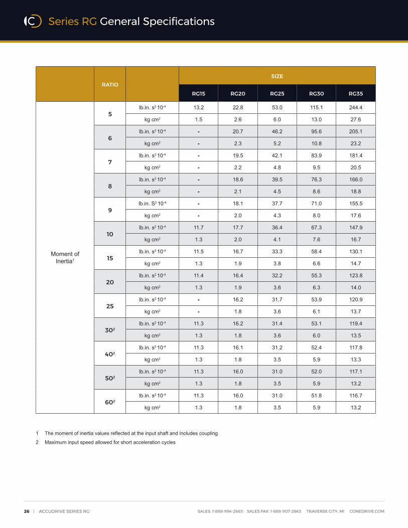
RATIOSIZE
RG15 RG20 RG25 RG30 RG35
Moment ofInertia1
5lb.in. s2 10-4 13.2 22.8 53.0 115.1 244.4
kg cm2 1.5 2.6 6.0 13.0 27.6
6lb.in. s2 10-4 - 20.7 46.2 95.6 205.1
kg cm2 - 2.3 5.2 10.8 23.2
7lb.in. s2 10-4 - 19.5 42.1 83.9 181.4
kg cm2 - 2.2 4.8 9.5 20.5
8lb.in. s2 10-4 - 18.6 39.5 76.3 166.0
kg cm2 - 2.1 4.5 8.6 18.8
9lb.in. S2 10-4 - 18.1 37.7 71.0 155.5
kg cm2 - 2.0 4.3 8.0 17.6
10lb.in. s2 10-4 11.7 17.7 36.4 67.3 147.9
kg cm2 1.3 2.0 4.1 7.6 16.7
15lb.in. s2 10-4 11.5 16.7 33.3 58.4 130.1
kg cm2 1.3 1.9 3.8 6.6 14.7
20lb.in. s2 10-4 11.4 16.4 32.2 55.3 123.8
kg cm2 1.3 1.9 3.6 6.3 14.0
25lb.in. s2 10-4 - 16.2 31.7 53.9 120.9
kg cm2 - 1.8 3.6 6.1 13.7
302lb.in. s2 10-4 11.3 16.2 31.4 53.1 119.4
kg cm2 1.3 1.8 3.6 6.0 13.5
402lb.in. s2 10-4 11.3 16.1 31.2 52.4 117.8
kg cm2 1.3 1.8 3.5 5.9 13.3
502lb.in. s2 10-4 11.3 16.0 31.0 52.0 117.1
kg cm2 1.3 1.8 3.5 5.9 13.2
602lb.in. s2 10-4 11.3 16.0 31.0 51.8 116.7
kg cm2 1.3 1.8 3.5 5.9 13.2
1 The moment of inertia values reflected at the input shaft and includes coupling
2 Maximum input speed allowed for short acceleration cycles
Series RG General Specifications

CONE DRIVE | 27SALES: 1-888-994-2663 SALES FAX: 1-888-907-2663 TRAVERSE CITY, MI CONEDRIVE.COM
RG15 Single Reduction
i : 1 Ratings UnitsN1 NOM (rpm) N1 PK T2 MAX
500 1,000 1,150 1,450 1,750 2,000 3,000 4,000 rpm lb-in Nm
5
P1 ME
hp 0.99 1.74 1.92 2.24 2.49 2.67 3.33 3.85
4000 1,610 181
kW 0.74 1.30 1.44 1.67 1.86 2.00 2.49 2.87
P1 TH
hp 0.99 1.74 1.82 1.82 1.82 1.79 1.61 1.54
kW 0.74 1.30 1.36 1.36 1.36 1.34 1.20 1.15
T2 ME
lb-in 548 488 469 434 399 374 306 264
Nm 62 55 53 49 45 42 35 30
T2 ACC
lb-in 593 548 538 517 504 488 427 374
Nm 67 62 61 58 57 55 48 42
η % 88 89 89 89 89 89 88 87
10
P1 ME
hp 0.68 1.22 1.36 1.60 1.80 1.94 2.42 2.79
4000 1,890 214
kW 0.51 0.91 1.01 1.19 1.34 1.44 1.80 2.08
P1 TH
hp 0.68 1.22 1.36 1.54 1.54 1.52 1.39 1.33
kW 0.51 0.91 1.01 1.15 1.15 1.14 1.03 1.00
T2 ME
lb-in 720 670 647 603 563 530 434 374
Nm 81 76 73 68 64 60 49 42
T2 ACC
lb-in 774 720 710 703 679 670 597 530
Nm 88 81 80 80 77 76 68 60
η % 84 87 87 87 87 87 86 85
15
P1 ME
hp 0.55 0.99 1.10 1.30 1.47 1.59 1.98 2.30
4000 1,890 213
kW 0.41 0.74 0.82 0.97 1.10 1.18 1.47 1.72
P1 TH
hp 0.55 0.99 1.10 1.30 1.33 1.32 1.22 1.18
kW 0.41 0.74 0.82 0.97 1.00 0.99 0.91 0.88
T2 ME
lb-in 848 798 772 722 676 636 520 451
Nm 96 90 87 82 76 72 59 51
T2 ACC
lb-in 896 848 843 826 809 798 715 636
Nm 101 96 95 93 91 90 81 72
η % 81 85 85 85 85 85 84 83
20
P1 ME
hp 0.42 0.76 0.85 1.00 1.13 1.22 1.52 1.77
4000 1,820 206
kW 0.32 0.57 0.63 0.75 0.84 0.91 1.13 1.32
P1 TH
hp 0.42 0.76 0.85 1.00 1.11 1.10 1.03 1.00
kW 0.32 0.57 0.63 0.75 0.83 0.82 0.77 0.75
T2 ME
lb-in 835 776 751 713 667 629 514 445
Nm 94 88 85 81 75 71 58 50
T2 ACC
lb-in 869 835 837 814 787 776 704 629
Nm 98 94 95 92 89 88 80 71
η % 78 81 81 82 82 82 81 80
30
P1 ME
hp 0.29 0.51 0.57 0.67 0.76 0.82 1.02 1.19
4000 1,670 189
kW 0.21 0.38 0.43 0.50 0.57 0.61 0.76 0.89
P1 TH
hp 0.29 0.51 0.57 0.67 0.76 0.82 0.82 0.80
kW 0.21 0.38 0.43 0.50 0.57 0.61 0.61 0.60
T2 ME
lb-in 768 739 724 678 634 598 488 423
Nm 87 84 82 77 72 68 55 48
T2 ACC
lb-in 807 768 763 771 755 739 669 598
Nm 91 87 86 87 85 84 76 68
η % 71 76 77 77 77 77 76 75
Other ratios are available. Please contact Cone Drive for ratios and ratings. See page 43 for rating definitions.
Series RG Size 15 Ratings

28 | ACCUDRIVE SERIES RG SALES: 1-888-994-2663 SALES FAX: 1-888-907-2663 TRAVERSE CITY, MI CONEDRIVE.COM
RG NEMA 15 Single Reduction
i : 1 Ratings UnitsN1 NOM (rpm) N1 PK T2 MAX
500 1,000 1,150 1,450 1,750 2,000 3,000 4,000 rpm lb-in Nm
Other ratios are available. Please contact Cone Drive for ratios and ratings. See page 43 for rating definitions.
40
P1 ME
hp 0.21 0.39 0.43 0.51 0.57 0.62 0.77 0.90
4000 1,500 169
kW 0.16 0.29 0.32 0.38 0.43 0.46 0.58 0.67
P1 TH
hp 0.21 0.39 0.43 0.51 0.57 0.62 0.70 0.69
kW 0.16 0.29 0.32 0.38 0.43 0.46 0.53 0.51
T2 ME
lb-in 730 704 690 647 604 570 465 403
Nm 83 80 78 73 68 64 53 46
T2 ACC
lb-in 732 730 734 743 720 704 639 570
Nm 83 83 83 84 81 80 72 64
η % 67 72 73 73 73 73 72 71
50
P1 ME
hp 0.17 0.31 0.35 0.41 0.46 0.50 0.62 0.72
4000 1,320 149
kW 0.13 0.23 0.26 0.31 0.34 0.37 0.46 0.54
P1 TH
hp 0.17 0.31 0.35 0.41 0.46 0.50 0.62 0.62
kW 0.13 0.23 0.26 0.31 0.34 0.37 0.46 0.47
T2 ME
lb-in 710 676 663 622 581 549 446 387
Nm 80 76 75 70 66 62 50 44
T2 ACC
lb-in 710 710 715 714 692 676 614 549
Nm 80 80 81 81 78 76 69 62
η % 65 69 70 70 70 70 69 68
60
P1 ME
hp 0.14 0.26 0.29 0.34 0.39 0.42 0.52 0.60
4000 1,300 146
kW 0.11 0.19 0.22 0.25 0.29 0.31 0.39 0.45
P1 TH
hp 0.14 0.26 0.29 0.34 0.39 0.42 0.52 0.53
kW 0.11 0.19 0.22 0.25 0.29 0.31 0.39 0.39
T2 ME
lb-in 668 648 636 596 558 526 428 354
Nm 76 73 72 67 63 59 48 40
T2 ACC
lb-in 672 668 673 674 663 648 589 526
Nm 76 76 76 76 75 73 67 59
η % 61 66 67 67 67 67 66 62
Series RG Size 15 Ratings

CONE DRIVE | 29SALES: 1-888-994-2663 SALES FAX: 1-888-907-2663 TRAVERSE CITY, MI CONEDRIVE.COM
RG20 Single Reduction
i : 1 Ratings UnitsN1 NOM (rpm) N1 PK T2 MAX
500 1,000 1,150 1,450 1,750 2,000 3,000 4,000 rpm lb-in Nm
5
P1 ME
hp 1.95 3.31 3.62 4.13 4.55 4.91 6.07 6.92
4000 3,320 375
kW 1.45 2.47 2.70 3.08 3.40 3.67 4.53 5.16
P1 TH
hp 1.95 3.00 3.00 3.00 3.00 2.95 2.55 2.40kW 1.45 2.24 2.24 2.24 2.24 2.20 1.90 1.79
T2 ME
lb-in 1,120 960 913 825 754 711 577 490Nm 126 108 103 93 85 80 65 55
T2 ACC
lb-in 1,210 1,120 1,090 1,040 1,000 960 812 711Nm 137 126 123 118 113 108 92 80
η % 91 92 92 92 92 92 91 90
6
P1 ME
hp 1.83 3.13 3.43 3.92 4.33 4.66 5.75 6.63
4000 3,600 407
kW 1.36 2.34 2.56 2.93 3.23 3.48 4.29 4.95
P1 TH
hp 1.83 2.86 2.86 2.86 2.86 2.81 2.44 2.31kW 1.36 2.13 2.13 2.13 2.13 2.10 1.82 1.72
T2 ME
lb-in 1,250 1,090 1,030 937 857 805 654 561Nm 141 123 117 106 97 91 74 63
T2 ACC
lb-in 1,350 1,250 1,220 1,170 1,130 1,090 923 805Nm 153 141 138 132 127 123 104 91
η % 90 92 92 92 92 91 90 90
7
P1 ME
hp 1.67 2.88 3.15 3.62 4.00 4.30 5.31 6.11
4000 3,720 421
kW 1.25 2.15 2.35 2.70 2.99 3.21 3.96 4.56
P1 TH
hp 1.67 2.73 2.73 2.73 2.73 2.68 2.35 2.22kW 1.25 2.04 2.04 2.04 2.04 2.00 1.75 1.66
T2 ME
lb-in 1,320 1,160 1,100 1,000 920 864 701 601Nm 149 131 125 113 104 98 79 68
T2 ACC
lb-in 1,430 1,320 1,290 1,240 1,200 1,160 989 864Nm 161 149 146 141 135 131 112 98
η % 89 91 91 91 91 91 90 89
8
P1 ME
hp 1.57 2.72 2.98 3.43 3.79 4.07 5.07 5.80
4000 3,870 438
kW 1.17 2.03 2.23 2.56 2.83 3.04 3.78 4.33
P1 TH
hp 1.57 2.61 2.61 2.61 2.61 2.57 2.26 2.14kW 1.17 1.95 1.95 1.95 1.95 1.92 1.69 1.60
T2 ME
lb-in 1,400 1,240 1,190 1,080 993 930 761 649Nm 159 140 134 122 112 105 86 73
T2 ACC
lb-in 1,510 1,400 1,370 1,330 1,280 1,240 1,070 930Nm 171 159 155 151 145 140 121 105
η % 89 91 91 91 91 91 89 89
9
P1 ME
hp 1.45 2.50 2.75 3.16 3.50 3.75 4.67 5.35
4000 3,900 440
kW 1.08 1.87 2.05 2.36 2.61 2.80 3.49 4.00
P1 TH
hp 1.45 2.50 2.50 2.50 2.50 2.46 2.18 2.07kW 1.08 1.87 1.87 1.87 1.87 1.84 1.62 1.54
T2 ME
lb-in 1,440 1,280 1,220 1,120 1,030 960 786 671Nm 163 145 138 126 116 108 89 76
T2 ACC
lb-in 1,550 1,440 1,410 1,370 1,320 1,280 1,100 960Nm 175 163 159 155 149 145 125 108
η % 88 90 90 90 90 90 89 88
10
P1 ME
hp 1.35 2.34 2.57 2.96 3.28 3.51 4.38 5.01
4000 3,910 442
kW 1.01 1.74 1.92 2.21 2.45 2.62 3.27 3.74
P1 TH
hp 1.35 2.34 2.40 2.40 2.40 2.37 2.10 2.00kW 1.01 1.74 1.79 1.79 1.79 1.77 1.57 1.49
T2 ME
lb-in 1,480 1,330 1,270 1,160 1,060 994 815 694Nm 167 150 143 131 120 112 92 79
T2 ACC
lb-in 1,580 1,480 1,450 1,420 1,360 1,330 1,140 994Nm 179 167 164 160 153 150 129 112
η % 87 90 90 90 90 90 89 88
15
P1 ME
hp 1.09 1.90 2.10 2.43 2.69 2.89 3.59 4.13
4000 3,930 444
kW 0.82 1.42 1.57 1.81 2.01 2.15 2.68 3.08
P1 TH
hp 1.09 1.90 2.00 2.00 2.00 1.98 1.79 1.71kW 0.82 1.42 1.49 1.49 1.49 1.47 1.33 1.28
T2 ME
lb-in 1,740 1,580 1,520 1,390 1,280 1,200 981 839Nm 197 179 172 157 144 135 111 95
T2 ACC
lb-in 1,840 1,740 1,720 1,670 1,620 1,580 1,370 1,200Nm 208 197 195 189 183 179 155 135
η % 84 88 88 88 88 88 87 86
Other ratios are available. Please contact Cone Drive for ratios and ratings. See page 43 for rating definitions.
Series RG Size 20 Ratings

30 | ACCUDRIVE SERIES RG SALES: 1-888-994-2663 SALES FAX: 1-888-907-2663 TRAVERSE CITY, MI CONEDRIVE.COM
RG20 Single Reduction
i : 1 Ratings UnitsN1 NOM (rpm) N1 PK T2 MAX
500 1,000 1,150 1,450 1,750 2,000 3,000 4,000 rpm lb-in Nm
Other ratios are available. Please contact Cone Drive for ratios and ratings. See page 43 for rating definitions.
20
P1 ME
hp 0.84 1.46 1.61 1.86 2.07 2.22 2.76 3.18
4000 3,800 429
kW 0.62 1.09 1.20 1.39 1.54 1.66 2.06 2.37
P1 TH
hp 0.84 1.46 1.50 1.60 1.60 1.58 1.46 1.41kW 0.62 1.09 1.12 1.19 1.19 1.18 1.09 1.05
T2 ME
lb-in 1,720 1,550 1,480 1,380 1,260 1,190 971 832Nm 194 175 167 156 143 134 110 94
T2 ACC
lb-in 1,780 1,720 1,720 1,650 1,580 1,550 1,360 1,190Nm 201 194 194 186 179 175 153 134
η % 81 84 84 85 85 85 84 83
25
P1 ME
hp 0.68 1.18 1.30 1.50 1.67 1.79 2.23 2.57
4000 3,620 409
kW 0.50 0.88 0.97 1.12 1.24 1.34 1.66 1.91
P1 TH
hp 0.68 1.18 1.30 1.50 1.50 1.49 1.38 1.33kW 0.50 0.88 0.97 1.12 1.12 1.11 1.03 1.00
T2 ME
lb-in 1,720 1,550 1,490 1,370 1,260 1,180 967 829Nm 195 175 169 155 142 134 109 94
T2 ACC
lb-in 1,750 1,720 1,690 1,620 1,590 1,550 1,350 1,180Nm 198 195 191 183 180 175 153 134
η % 81 83 84 84 84 84 83 82
30
P1 ME
hp 0.56 0.99 1.09 1.26 1.39 1.50 1.87 2.15
4000 3,480 393
kW 0.42 0.74 0.81 0.94 1.04 1.12 1.39 1.60
P1 TH
hp 0.56 0.99 1.09 1.20 1.20 1.19 1.12 1.09kW 0.42 0.74 0.81 0.90 0.90 0.89 0.84 0.81
T2 ME
lb-in 1,580 1,480 1,430 1,310 1,210 1,130 925 792Nm 179 167 161 148 136 128 105 90
T2 ACC
lb-in 1,660 1,580 1,570 1,560 1,520 1,480 1,290 1,130Nm 188 179 177 177 172 167 146 128
η % 74 79 80 80 80 80 79 78
40
P1 ME
hp 0.43 0.74 0.82 0.95 1.05 1.13 1.41 1.62
4000 3,140 354
kW 0.32 0.56 0.61 0.71 0.79 0.84 1.05 1.21
P1 TH
hp 0.43 0.74 0.82 0.95 1.00 0.99 0.94 0.92kW 0.32 0.56 0.61 0.71 0.75 0.74 0.70 0.69
T2 ME
lb-in 1,510 1,410 1,370 1,260 1,150 1,080 883 756Nm 171 160 154 142 130 122 100 85
T2 ACC
lb-in 1,510 1,510 1,510 1,510 1,450 1,410 1,240 1,080Nm 171 171 171 171 164 160 140 122
η % 70 75 76 76 76 76 75 74
50
P1 ME
hp 0.34 0.60 0.66 0.76 0.84 0.91 1.13 1.30
4000 2,780 315
kW 0.25 0.45 0.49 0.57 0.63 0.68 0.84 0.97
P1 TH
hp 0.34 0.60 0.66 0.76 0.84 0.88 0.84 0.83kW 0.25 0.45 0.49 0.57 0.63 0.66 0.63 0.62
T2 ME
lb-in 1,470 1,360 1,320 1,210 1,110 1,040 850 728Nm 166 154 149 137 125 118 96 82
T2 ACC
lb-in 1,470 1,470 1,470 1,460 1,400 1,360 1,190 1,040Nm 166 166 167 165 158 154 135 118
η % 68 72 73 73 73 73 72 71
60
P1 ME
hp 0.28 0.50 0.55 0.64 0.71 0.76 0.94 1.09
4000 2,740 309
kW 0.21 0.37 0.41 0.48 0.53 0.57 0.70 0.81
P1 TH
hp 0.28 0.50 0.55 0.64 0.71 0.76 0.76 0.69kW 0.21 0.37 0.41 0.48 0.53 0.57 0.57 0.51
T2 ME
lb-in 1,390 1,300 1,270 1,160 1,070 1,000 816 668Nm 157 147 143 131 121 113 92 76
T2 ACC
lb-in 1,390 1,390 1,390 1,380 1,340 1,300 1,150 1,000Nm 157 157 157 156 152 147 129 113
η % 64 69 70 70 70 70 69 65
Series RG Size 20 Ratings

CONE DRIVE | 31SALES: 1-888-994-2663 SALES FAX: 1-888-907-2663 TRAVERSE CITY, MI CONEDRIVE.COM
RG25 Single Reduction
i : 1 Ratings UnitsN1 NOM (rpm) N1 PK T2 MAX
500 1,000 1,150 1,450 1,750 2,000 3,000 4,000 rpm lb-in Nm
5
P1 ME
hp 3.76 6.10 6.58 7.43 8.24 8.87 10.80 11.80
4000 6,570 742
kW 2.81 4.55 4.91 5.55 6.15 6.62 8.05 8.84
P1 TH
hp 3.56 4.00 4.00 4.00 4.00 3.93 3.39 3.20kW 2.65 2.99 2.99 2.99 2.99 2.93 2.53 2.39
T2 ME
lb-in 2,160 1,770 1,660 1,490 1,370 1,280 1,030 840Nm 244 200 187 168 154 145 116 95
T2 ACC
lb-in 2,370 2,160 2,100 1,970 1,870 1,770 1,470 1,280Nm 268 244 237 222 211 200 166 145
η % 91 92 92 92 92 92 91 90
6
P1 ME
hp 3.53 5.77 6.25 7.04 7.81 8.41 10.20 11.40
4000 7,140 807
kW 2.63 4.31 4.66 5.26 5.83 6.27 7.62 8.48
P1 TH
hp 3.27 3.81 3.81 3.81 3.81 3.75 3.26 3.08kW 2.44 2.84 2.84 2.84 2.84 2.80 2.43 2.30
T2 ME
lb-in 2,410 2,000 1,880 1,680 1,550 1,450 1,160 963Nm 272 226 213 190 175 164 131 109
T2 ACC
lb-in 2,640 2,410 2,340 2,220 2,100 2,000 1,660 1,450Nm 298 272 264 250 237 226 188 164
η % 90 92 92 92 92 91 90 90
7
P1 ME
hp 3.24 5.32 5.75 6.52 7.24 7.75 9.45 10.50
4000 7,400 836
kW 2.42 3.97 4.29 4.86 5.40 5.78 7.05 7.87
P1 TH
hp 3.02 3.64 3.64 3.64 3.64 3.58 3.13 2.96kW 2.25 2.71 2.71 2.71 2.71 2.67 2.33 2.21
T2 ME
lb-in 2,560 2,140 2,010 1,810 1,660 1,560 1,250 1,040Nm 289 242 227 204 188 176 141 117
T2 ACC
lb-in 2,790 2,560 2,480 2,360 2,240 2,140 1,770 1,560Nm 315 289 281 267 253 242 201 176
η % 89 91 91 91 91 91 90 89
8
P1 ME
hp 3.04 5.03 5.46 6.17 6.86 7.32 9.00 10.10
4000 7,690 869
kW 2.27 3.76 4.07 4.60 5.12 5.47 6.71 7.52
P1 TH
hp 2.81 3.48 3.48 3.48 3.48 3.42 3.01 2.86kW 2.09 2.60 2.60 2.60 2.60 2.56 2.25 2.13
T2 ME
lb-in 2,720 2,300 2,170 1,950 1,790 1,670 1,350 1,130Nm 307 260 245 220 203 189 153 127
T2 ACC
lb-in 2,950 2,720 2,640 2,540 2,400 2,300 1,920 1,670Nm 334 307 299 287 271 260 217 189
η % 89 91 91 91 91 91 89 89
9
P1 ME
hp 2.80 4.64 5.03 5.70 6.32 6.77 8.29 9.30
4000 7,710 872
kW 2.09 3.46 3.75 4.25 4.71 5.05 6.19 6.94
P1 TH
hp 2.62 3.33 3.33 3.33 3.33 3.28 2.90 2.76kW 1.96 2.49 2.49 2.49 2.49 2.45 2.17 2.06
T2 ME
lb-in 2,790 2,380 2,240 2,010 1,850 1,730 1,400 1,170Nm 315 269 253 228 209 196 158 132
T2 ACC
lb-in 3,020 2,790 2,710 2,620 2,470 2,380 1,980 1,730Nm 342 315 306 296 279 269 224 196
η % 88 90 90 90 90 90 89 88
10
P1 ME
hp 2.61 4.33 4.70 5.33 5.90 6.33 7.77 8.75
4000 7,770 878
kW 1.95 3.23 3.51 3.98 4.40 4.72 5.80 6.53
P1 TH
hp 2.46 3.20 3.20 3.20 3.20 3.15 2.80 2.67kW 1.84 2.39 2.39 2.39 2.39 2.35 2.09 1.99
T2 ME
lb-in 2,860 2,460 2,320 2,080 1,910 1,790 1,450 1,210Nm 323 278 262 236 216 202 163 137
T2 ACC
lb-in 3,090 2,860 2,790 2,700 2,550 2,460 2,050 1,790Nm 349 323 315 305 288 278 232 202
η % 87 90 90 90 90 90 89 88
15
P1 ME
hp 2.12 3.55 3.86 4.37 4.82 5.19 6.38 7.20
4000 7,790 880
kW 1.58 2.65 2.88 3.26 3.60 3.87 4.76 5.38
P1 TH
hp 2.02 2.67 2.67 2.67 2.67 2.64 2.38 2.29kW 1.51 1.99 1.99 1.99 1.99 1.97 1.78 1.71
T2 ME
lb-in 3,380 2,950 2,790 2,510 2,290 2,150 1,740 1,460Nm 382 334 315 283 259 243 197 165
T2 ACC
lb-in 3,580 3,380 3,320 3,190 3,050 2,950 2,470 2,150Nm 405 382 375 360 345 334 279 243
η % 84 88 88 88 88 88 87 86
Other ratios are available. Please contact Cone Drive for ratios and ratings. See page 43 for rating definitions.
Series RG Size 25 Ratings

32 | ACCUDRIVE SERIES RG SALES: 1-888-994-2663 SALES FAX: 1-888-907-2663 TRAVERSE CITY, MI CONEDRIVE.COM
RG25 Single Reduction
i : 1 Ratings UnitsN1 NOM (rpm) N1 PK T2 MAX
500 1,000 1,150 1,450 1,750 2,000 3,000 4,000 rpm lb-in Nm
Other ratios are available. Please contact Cone Drive for ratios and ratings. See page 43 for rating definitions.
20
P1 ME
hp 1.62 2.72 2.96 3.36 3.71 3.99 4.91 5.56
4000 7,540 851
kW 1.21 2.03 2.21 2.50 2.77 2.97 3.66 4.15
P1 TH
hp 1.62 2.00 2.00 2.13 2.13 2.11 1.95 1.88kW 1.21 1.49 1.49 1.59 1.59 1.58 1.45 1.40
T2 ME
lb-in 3,330 2,880 2,720 2,480 2,270 2,130 1,720 1,450Nm 376 325 308 280 257 241 195 164
T2 ACC
lb-in 3,480 3,330 3,300 3,150 2,980 2,880 2,440 2,130Nm 393 376 373 355 337 325 276 241
η % 81 84 84 85 85 85 84 83
25
P1 ME
hp 1.31 2.19 2.39 2.71 3.00 3.21 3.96 4.48
4000 7,180 812
kW 0.98 1.64 1.78 2.02 2.24 2.40 2.96 3.35
P1 TH
hp 1.31 1.91 2.00 2.00 2.00 1.98 1.84 1.78kW 0.98 1.43 1.49 1.49 1.49 1.48 1.37 1.33
T2 ME
lb-in 3,340 2,880 2,750 2,470 2,270 2,120 1,720 1,450Nm 377 325 310 279 256 240 194 164
T2 ACC
lb-in 3,410 3,340 3,250 3,090 3,000 2,880 2,430 2,120Nm 385 377 367 350 339 325 275 240
η % 81 83 84 84 84 84 83 82
30
P1 ME
hp 1.10 1.83 2.00 2.27 2.51 2.70 3.32 3.76
4000 6,900 780
kW 0.82 1.37 1.49 1.69 1.87 2.01 2.48 2.80
P1 TH
hp 1.10 1.54 1.60 1.60 1.60 1.59 1.49 1.45kW 0.82 1.15 1.19 1.19 1.19 1.19 1.11 1.09
T2 ME
lb-in 3,070 2,750 2,630 2,370 2,170 2,040 1,640 1,390Nm 347 311 297 267 245 230 186 157
T2 ACC
lb-in 3,240 3,070 3,020 2,990 2,870 2,750 2,330 2,040Nm 366 347 341 338 324 311 263 230
η % 74 79 80 80 80 80 79 78
40
P1 ME
hp 0.83 1.39 1.51 1.71 1.90 2.03 2.50 2.83
4000 6,220 703
kW 0.62 1.03 1.13 1.28 1.41 1.52 1.87 2.12
P1 TH
hp 0.83 1.29 1.33 1.33 1.33 1.33 1.26 1.23kW 0.62 0.97 1.00 1.00 1.00 0.99 0.94 0.92
T2 ME
lb-in 2,930 2,630 2,510 2,260 2,070 1,950 1,570 1,320Nm 331 297 284 255 234 220 177 149
T2 ACC
lb-in 2,950 2,930 2,910 2,890 2,740 2,630 2,230 1,950Nm 334 331 329 327 309 297 252 220
η % 70 75 76 76 76 76 75 74
50
P1 ME
hp 0.66 1.11 1.21 1.37 1.52 1.63 2.01 2.28
4000 5,520 624
kW 0.49 0.83 0.90 1.03 1.13 1.22 1.50 1.70
P1 TH
hp 0.66 1.11 1.19 1.19 1.19 1.18 1.13 1.10kW 0.49 0.83 0.88 0.88 0.88 0.88 0.84 0.82
T2 ME
lb-in 2,850 2,530 2,420 2,180 2,000 1,870 1,510 1,270Nm 322 286 274 246 226 212 170 144
T2 ACC
lb-in 2,860 2,850 2,840 2,780 2,640 2,530 2,150 1,870Nm 323 322 321 314 298 286 243 212
η % 68 72 73 73 73 73 72 71
60
P1 ME
hp 0.55 0.93 1.01 1.15 1.27 1.36 1.68 1.90
4000 5,430 613
kW 0.41 0.69 0.75 0.86 0.95 1.02 1.25 1.42
P1 TH
hp 0.55 0.93 1.01 1.07 1.07 1.06 1.02 0.91kW 0.41 0.69 0.75 0.80 0.80 0.79 0.76 0.68
T2 ME
lb-in 2,690 2,430 2,330 2,090 1,920 1,800 1,450 1,170Nm 304 274 263 237 217 203 164 132
T2 ACC
lb-in 2,720 2,690 2,690 2,630 2,530 2,430 2,060 1,800Nm 308 304 303 297 286 274 233 203
η % 64 69 70 70 70 70 69 65
Series RG Size 25 Ratings

CONE DRIVE | 33SALES: 1-888-994-2663 SALES FAX: 1-888-907-2663 TRAVERSE CITY, MI CONEDRIVE.COM
RG30 Single Reduction
i : 1 Ratings UnitsN1 NOM (rpm) N1 PK T2 MAX
500 1,000 1,150 1,450 1,750 2,000 3,000 4,000 rpm lb-in Nm
5
P1 ME
hp 6.51 10.10 10.80 12.30 13.60 14.50 17.20 18.90
4000 11,600 1,310
kW 4.86 7.51 8.07 9.18 10.10 10.80 12.80 14.10
P1 TH
hp 4.22 4.75 4.75 4.75 4.75 4.67 4.03 3.80kW 3.15 3.54 3.54 3.54 3.54 3.48 3.01 2.84
T2 ME
lb-in 3,730 2,920 2,730 2,460 2,250 2,100 1,630 1,340Nm 422 330 308 278 255 237 185 151
T2 ACC
lb-in 4,200 3,730 3,590 3,320 3,110 2,920 2,420 2,100Nm 474 422 406 376 351 330 273 237
η % 91 92 92 92 92 92 91 90
6
P1 ME
hp 6.12 9.56 10.30 11.70 12.90 13.80 16.50 18.00
4000 12,600 1,430
kW 4.57 7.14 7.69 8.71 9.64 10.30 12.30 13.40
P1 TH
hp 3.88 4.52 4.52 4.52 4.52 4.45 3.87 3.65kW 2.89 3.38 3.38 3.38 3.38 3.32 2.89 2.73
T2 ME
lb-in 4,170 3,310 3,100 2,790 2,560 2,390 1,870 1,520Nm 472 374 351 315 289 270 211 172
T2 ACC
lb-in 4,660 4,170 4,030 3,750 3,510 3,310 2,750 2,390Nm 527 472 455 424 397 374 310 270
η % 90 92 92 92 92 91 90 90
7
P1 ME
hp 5.63 8.86 9.54 10.80 12.00 12.80 15.30 16.80
4000 13,100 1,480
kW 4.20 6.61 7.12 8.09 8.94 9.52 11.50 12.50
P1 TH
hp 3.58 4.32 4.32 4.32 4.32 4.25 3.72 3.52kW 2.68 3.22 3.22 3.22 3.22 3.17 2.77 2.63
T2 ME
lb-in 4,440 3,570 3,340 3,010 2,750 2,560 2,030 1,650Nm 502 403 377 340 311 290 229 186
T2 ACC
lb-in 4,920 4,440 4,290 4,020 3,770 3,570 2,960 2,560Nm 556 502 484 455 426 403 334 290
η % 89 91 91 91 91 91 90 89
8
P1 ME
hp 5.35 8.58 9.26 10.40 11.60 12.40 15.00 16.50
4000 13,700 1,550
kW 3.99 6.40 6.91 7.80 8.63 9.29 11.20 12.30
P1 TH
hp 3.33 4.13 4.13 4.13 4.13 4.07 3.58 3.39kW 2.49 3.08 3.08 3.08 3.08 3.03 2.67 2.53
T2 ME
lb-in 4,780 3,930 3,690 3,300 3,030 2,850 2,260 1,850Nm 540 444 417 373 342 322 255 209
T2 ACC
lb-in 5,240 4,780 4,630 4,400 4,130 3,930 3,260 2,850Nm 592 540 524 497 467 444 369 322
η % 89 91 91 91 91 91 89 89
9
P1 ME
hp 4.94 7.95 8.57 9.72 10.70 11.50 14.00 15.30
4000 13,800 1,560
kW 3.69 5.94 6.40 7.25 8.02 8.62 10.40 11.40
P1 TH
hp 3.11 3.96 3.96 3.96 3.96 3.90 3.45 3.28kW 2.32 2.95 2.95 2.95 2.95 2.91 2.57 2.44
T2 ME
lb-in 4,920 4,080 3,820 3,440 3,150 2,960 2,350 1,920Nm 556 461 432 388 356 334 266 217
T2 ACC
lb-in 5,370 4,920 4,770 4,550 4,270 4,080 3,380 2,960Nm 607 556 538 514 482 461 381 334
η % 88 90 90 90 90 90 89 88
10
P1 ME
hp 4.60 7.43 8.02 9.07 10.00 10.80 13.10 14.30
4000 13,800 1,560
kW 3.43 5.54 5.98 6.77 7.48 8.05 9.76 10.70
P1 TH
hp 2.92 3.80 3.80 3.80 3.80 3.75 3.33 3.17kW 2.18 2.84 2.84 2.84 2.84 2.80 2.48 2.36
T2 ME
lb-in 5,040 4,210 3,950 3,550 3,250 3,060 2,430 1,990Nm 570 476 447 401 367 345 275 224
T2 ACC
lb-in 5,500 5,040 4,890 4,700 4,400 4,210 3,490 3,060Nm 622 570 553 531 498 476 394 345
η % 87 90 90 90 90 90 89 88
15
P1 ME
hp 3.74 6.09 6.58 7.42 8.23 8.86 10.80 11.90
4000 13,900 1,570
kW 2.79 4.54 4.91 5.54 6.14 6.61 8.04 8.89
P1 TH
hp 2.40 3.17 3.17 3.17 3.17 3.13 2.83 2.71kW 1.79 2.36 2.36 2.36 2.36 2.34 2.11 2.03
T2 ME
lb-in 5,950 5,070 4,760 4,260 3,910 3,680 2,940 2,420Nm 672 572 538 481 442 416 332 274
T2 ACC
lb-in 6,380 5,950 5,840 5,560 5,280 5,070 4,210 3,680Nm 721 672 660 628 596 572 475 416
η % 84 88 88 88 88 88 87 86
Other ratios are available. Please contact Cone Drive for ratios and ratings. See page 43 for rating definitions.
Series RG Size 30 Ratings

34 | ACCUDRIVE SERIES RG SALES: 1-888-994-2663 SALES FAX: 1-888-907-2663 TRAVERSE CITY, MI CONEDRIVE.COM
RG30 Single Reduction
i : 1 Ratings UnitsN1 NOM (rpm) N1 PK T2 MAX
500 1,000 1,150 1,450 1,750 2,000 3,000 4,000 rpm lb-in Nm
20
P1 ME
hp 2.87 4.68 5.06 5.70 6.33 6.81 8.28 9.18
4000 13,500 1,520
kW 2.14 3.49 3.77 4.26 4.73 5.08 6.18 6.85
P1 TH
hp 2.04 2.37 2.37 2.53 2.53 2.51 2.31 2.24kW 1.52 1.77 1.77 1.89 1.89 1.87 1.73 1.67
T2 ME
lb-in 5,880 4,950 4,660 4,210 3,880 3,640 2,910 2,400Nm 664 560 526 476 438 411 328 271
T2 ACC
lb-in 6,190 5,880 5,830 5,490 5,160 4,950 4,160 3,640Nm 700 664 658 620 583 560 470 411
η % 81 84 84 85 85 85 84 83
25
P1 ME
hp 2.31 3.78 4.09 4.60 5.12 5.50 6.68 7.43
4000 12,800 1,450
kW 1.73 2.82 3.05 3.43 3.82 4.10 4.99 5.54
P1 TH
hp 2.00 2.27 2.37 2.37 2.37 2.35 2.18 2.11kW 1.49 1.69 1.77 1.77 1.77 1.76 1.63 1.58
T2 ME
lb-in 5,910 4,960 4,700 4,200 3,870 3,630 2,900 2,400Nm 667 560 532 474 437 410 327 271
T2 ACC
lb-in 6,080 5,910 5,740 5,410 5,200 4,960 4,140 3,630Nm 687 667 649 611 587 560 468 410
η % 81 83 84 84 84 84 83 82
30
P1 ME
hp 1.94 3.16 3.42 3.85 4.28 4.60 5.59 6.22
4000 12,300 1,390
kW 1.44 2.36 2.55 2.87 3.20 3.44 4.17 4.64
P1 TH
hp 1.47 1.83 1.90 1.90 1.90 1.89 1.77 1.73kW 1.10 1.37 1.42 1.42 1.42 1.41 1.32 1.29
T2 ME
lb-in 5,430 4,740 4,500 4,020 3,700 3,480 2,770 2,290Nm 613 536 509 454 418 393 313 259
T2 ACC
lb-in 5,780 5,430 5,330 5,220 4,980 4,740 3,960 3,480Nm 653 613 602 590 562 536 448 393
η % 74 79 80 80 80 80 79 78
40
P1 ME
hp 1.46 2.39 2.58 2.91 3.23 3.47 4.22 4.69
4000 11,100 1,260
kW 1.09 1.78 1.93 2.17 2.41 2.59 3.15 3.50
P1 TH
hp 1.28 1.54 1.58 1.58 1.58 1.57 1.49 1.46kW 0.96 1.15 1.18 1.18 1.18 1.17 1.12 1.09
T2 ME
lb-in 5,170 4,530 4,300 3,840 3,530 3,320 2,640 2,190Nm 584 511 486 434 399 375 299 247
T2 ACC
lb-in 5,260 5,170 5,140 5,050 4,750 4,530 3,790 3,320Nm 595 584 580 571 536 511 429 375
η % 70 75 76 76 76 76 75 74
50
P1 ME
hp 1.17 1.92 2.07 2.34 2.59 2.79 3.39 3.77
4000 9,860 1,110
kW 0.87 1.43 1.55 1.74 1.93 2.08 2.53 2.81
P1 TH
hp 1.17 1.37 1.41 1.41 1.41 1.40 1.34 1.31kW 0.87 1.02 1.05 1.05 1.05 1.04 1.00 0.98
T2 ME
lb-in 5,040 4,360 4,140 3,710 3,410 3,200 2,550 2,110Nm 569 493 468 419 385 362 288 238
T2 ACC
lb-in 5,090 5,040 5,010 4,860 4,570 4,360 3,650 3,200Nm 575 569 566 549 516 493 413 362
η % 68 72 73 73 73 73 72 71
60
P1 ME
hp 0.98 1.60 1.73 1.95 2.16 2.33 2.83 3.15
4000 9,700 1,100
kW 0.73 1.19 1.29 1.46 1.62 1.74 2.11 2.35
P1 TH
hp 0.98 1.24 1.27 1.27 1.27 1.26 1.21 1.09kW 0.73 0.92 0.95 0.95 0.95 0.94 0.90 0.81
T2 ME
lb-in 4,750 4,190 3,980 3,560 3,270 3,080 2,440 1,930Nm 537 473 450 402 370 347 276 219
T2 ACC
lb-in 4,850 4,750 4,730 4,600 4,390 4,190 3,510 3,080Nm 548 537 534 520 497 473 396 347
η % 64 69 70 70 70 70 69 65
Other ratios are available. Please contact Cone Drive for ratios and ratings. See page 43 for rating definitions.
Series RG Size 30 Ratings

CONE DRIVE | 35SALES: 1-888-994-2663 SALES FAX: 1-888-907-2663 TRAVERSE CITY, MI CONEDRIVE.COM
RG35 Single Reduction
i : 1 Ratings UnitsN1 NOM (rpm) N1 PK T2 MAX
500 1,000 1,150 1,450 1,750 2,000 3,000 4,000 rpm lb-in Nm
5
P1 ME
hp 11.70 17.50 19.00 21.50 23.50 24.90 28.90 32.10
4000 21,400 2,420
kW 8.73 13.10 14.20 16.00 17.60 18.60 21.60 24.00
P1 TH
hp 8.33 9.38 9.38 9.38 9.38 9.21 7.95 7.50kW 6.22 7.00 7.00 7.00 7.00 6.87 5.94 5.60
T2 ME
lb-in 6,710 5,080 4,790 4,290 3,900 3,610 2,750 2,280Nm 758 574 541 485 440 408 311 257
T2 ACC
lb-in 7,720 6,710 6,410 5,850 5,410 5,080 4,220 3,610Nm 872 758 724 661 611 574 477 408
η % 91 92 92 92 92 92 91 90
6
P1 ME
hp 11.00 16.70 18.00 20.40 22.40 23.90 27.50 30.70
4000 23,300 2,640
kW 8.24 12.50 13.50 15.20 16.70 17.80 20.60 22.90
P1 TH
hp 7.65 8.93 8.93 8.93 8.93 8.78 7.63 7.21kW 5.71 6.66 6.66 6.66 6.66 6.55 5.69 5.38
T2 ME
lb-in 7,530 5,780 5,430 4,880 4,430 4,130 3,130 2,600Nm 851 653 614 551 501 466 354 294
T2 ACC
lb-in 8,570 7,530 7,200 6,630 6,140 5,780 4,800 4,130Nm 969 851 814 749 693 653 542 466
η % 90 92 92 92 92 91 90 90
7
P1 ME
hp 10.20 15.50 16.70 18.90 20.80 22.10 25.80 28.60
4000 24,200 2,730
kW 7.59 11.50 12.40 14.10 15.50 16.50 19.30 21.30
P1 TH
hp 7.08 8.52 8.52 8.52 8.52 8.39 7.33 6.94kW 5.28 6.36 6.36 6.36 6.36 6.26 5.47 5.18
T2 ME
lb-in 8,020 6,220 5,830 5,240 4,780 4,450 3,410 2,810Nm 906 703 659 593 540 503 386 318
T2 ACC
lb-in 9,080 8,020 7,680 7,130 6,580 6,220 5,170 4,450Nm 1,030 906 868 806 744 703 584 503
η % 89 91 91 91 91 91 90 89
8
P1 ME
hp 9.68 14.90 16.00 18.20 20.00 21.50 25.40 27.90
4000 25,300 2,860
kW 7.23 11.10 12.00 13.60 15.00 16.00 18.90 20.80
P1 TH
hp 6.58 8.15 8.15 8.15 8.15 8.03 7.06 6.70kW 4.91 6.08 6.08 6.08 6.08 5.99 5.27 5.00
T2 ME
lb-in 8,650 6,840 6,380 5,740 5,240 4,910 3,810 3,120Nm 978 772 721 649 593 554 431 353
T2 ACC
lb-in 9,640 8,650 8,310 7,790 7,220 6,840 5,660 4,910Nm 1,090 978 939 880 816 772 639 554
η % 89 91 91 91 91 91 89 89
9
P1 ME
hp 8.91 13.80 14.80 16.90 18.60 19.80 23.50 25.90
4000 25,400 2,870
kW 6.65 10.30 11.10 12.60 13.90 14.80 17.60 19.30
P1 TH
hp 6.15 7.81 7.81 7.81 7.81 7.70 6.80 6.47kW 4.59 5.83 5.83 5.83 5.83 5.74 5.08 4.83
T2 ME
lb-in 8,880 7,080 6,610 5,960 5,460 5,080 3,960 3,250Nm 1,000 800 746 674 616 574 448 367
T2 ACC
lb-in 9,890 8,880 8,550 8,050 7,470 7,080 5,860 5,080Nm 1,120 1,000 966 910 844 800 662 574
η % 88 90 90 90 90 90 89 88
10
P1 ME
hp 8.31 12.90 13.90 15.70 17.40 18.50 22.00 24.10
4000 25,500 2,880
kW 6.20 9.62 10.30 11.70 13.00 13.80 16.40 18.00
P1 TH
hp 5.77 7.50 7.50 7.50 7.50 7.39 6.56 6.25kW 4.31 5.60 5.60 5.60 5.60 5.52 4.90 4.66
T2 ME
lb-in 9,110 7,320 6,840 6,160 5,640 5,250 4,100 3,340Nm 1,030 827 773 696 637 593 463 378
T2 ACC
lb-in 10,100 9,110 8,780 8,310 7,690 7,320 6,030 5,250Nm 1,140 1,030 992 939 869 827 681 593
η % 87 90 90 90 90 90 89 88
15
P1 ME
hp 6.77 10.60 11.40 12.90 14.30 15.30 18.20 19.90
4000 25,600 2,890
kW 5.05 7.90 8.50 9.64 10.70 11.40 13.60 14.90
P1 TH
hp 4.74 6.25 6.25 6.25 6.25 6.18 5.59 5.36kW 3.54 4.66 4.66 4.66 4.66 4.61 4.17 4.00
T2 ME
lb-in 10,800 8,800 8,240 7,410 6,790 6,340 4,970 4,050Nm 1,220 995 931 837 767 716 561 457
T2 ACC
lb-in 11,700 10,800 10,500 9,860 9,250 8,800 7,290 6,340Nm 1,320 1,220 1,190 1,110 1,050 995 824 716
η % 84 88 88 88 88 88 87 86
Other ratios are available. Please contact Cone Drive for ratios and ratings. See page 43 for rating definitions.
Series RG Size 35 Ratings

36 | ACCUDRIVE SERIES RG SALES: 1-888-994-2663 SALES FAX: 1-888-907-2663 TRAVERSE CITY, MI CONEDRIVE.COM
RG35 Single Reduction
i : 1 Ratings UnitsN1 NOM (rpm) N1 PK T2 MAX
500 1,000 1,150 1,450 1,750 2,000 3,000 4,000 rpm lb-in Nm
20
P1 ME
hp 5.19 8.13 8.76 9.92 11.00 11.70 14.00 15.40
4000 24,800 2,800
kW 3.88 6.06 6.54 7.41 8.20 8.75 10.50 11.50
P1 TH
hp 4.02 4.69 4.69 5.00 5.00 4.95 4.57 4.41kW 3.00 3.50 3.50 3.73 3.73 3.70 3.41 3.29
T2 ME
lb-in 10,700 8,600 8,060 7,330 6,720 6,270 4,930 4,020Nm 1,200 972 911 829 760 709 556 454
T2 ACC
lb-in 11,400 10,700 10,500 9,740 9,050 8,600 7,210 6,270Nm 1,280 1,200 1,180 1,100 1,020 972 814 709
η % 81 84 84 85 85 85 84 83
25
P1 ME
hp 4.19 6.56 7.06 8.02 8.87 9.48 11.40 12.40
4000 23,600 2,670
kW 3.13 4.90 5.27 5.98 6.62 7.07 8.47 9.24
P1 TH
hp 3.95 4.48 4.69 4.69 4.69 4.65 4.30 4.17kW 2.95 3.34 3.50 3.50 3.50 3.47 3.21 3.11
T2 ME
lb-in 10,700 8,610 8,130 7,320 6,710 6,260 4,920 4,000Nm 1,210 973 919 827 758 708 556 452
T2 ACC
lb-in 11,200 10,700 10,300 9,600 9,130 8,610 7,190 6,260Nm 1,260 1,210 1,170 1,080 1,030 973 812 708
η % 81 83 84 84 84 84 83 82
30
P1 ME
hp 3.51 5.49 5.91 6.71 7.42 7.93 9.51 10.40
4000 22,700 2,570
kW 2.62 4.09 4.41 5.01 5.54 5.92 7.10 7.73
P1 TH
hp 2.90 3.62 3.75 3.75 3.75 3.72 3.50 3.41kW 2.17 2.70 2.80 2.80 2.80 2.78 2.61 2.54
T2 ME
lb-in 9,830 8,220 7,770 7,000 6,420 5,990 4,710 3,820Nm 1,110 929 878 791 725 676 532 432
T2 ACC
lb-in 10,600 9,830 9,590 9,270 8,720 8,220 6,870 5,990Nm 1,200 1,110 1,080 1,050 985 929 777 676
η % 74 79 80 80 80 80 79 78
40
P1 ME
hp 2.64 4.14 4.46 5.07 5.60 5.98 7.18 7.83
4000 20,500 2,310
kW 1.97 3.09 3.33 3.78 4.18 4.46 5.36 5.84
P1 TH
hp 2.53 3.03 3.12 3.12 3.12 3.11 2.95 2.88kW 1.89 2.26 2.33 2.33 2.33 2.32 2.20 2.15
T2 ME
lb-in 9,370 7,860 7,430 6,690 6,130 5,720 4,500 3,650Nm 1,060 888 840 756 693 646 508 413
T2 ACC
lb-in 9,670 9,370 9,240 8,970 8,320 7,860 6,580 5,720Nm 1,090 1,060 1,040 1,010 941 888 743 646
η % 70 75 76 76 76 76 75 74
50
P1 ME
hp 2.12 3.32 3.58 4.06 4.50 4.80 5.76 6.29
4000 18,200 2,050
kW 1.58 2.48 2.67 3.03 3.36 3.58 4.30 4.69
P1 TH
hp 2.12 2.70 2.78 2.78 2.78 2.76 2.64 2.59kW 1.58 2.02 2.07 2.07 2.07 2.06 1.97 1.93
T2 ME
lb-in 9,120 7,570 7,160 6,450 5,910 5,510 4,330 3,520Nm 1,030 855 809 728 668 622 489 397
T2 ACC
lb-in 9,340 9,120 9,010 8,630 8,020 7,570 6,330 5,510Nm 1,060 1,030 1,020 975 906 855 716 622
η % 68 72 73 73 73 73 72 71
60
P1 ME
hp 1.77 2.78 2.99 3.39 3.75 4.01 4.81 5.25
4000 17,900 2,020
kW 1.32 2.07 2.23 2.53 2.80 2.99 3.59 3.92
P1 TH
hp 1.77 2.44 2.50 2.50 2.50 2.49 2.39 2.14kW 1.32 1.82 1.87 1.87 1.87 1.86 1.78 1.60
T2 ME
lb-in 8,610 7,280 6,890 6,190 5,680 5,290 4,160 3,230Nm 972 822 778 700 642 598 470 365
T2 ACC
lb-in 8,910 8,610 8,510 8,170 7,700 7,280 6,080 5,290Nm 1,010 972 961 923 870 822 688 598
η % 64 69 70 70 70 70 69 65
Other ratios are available. Please contact Cone Drive for ratios and ratings. See page 43 for rating definitions.
Series RG Size 35 Ratings

CONE DRIVE | 37SALES: 1-888-994-2663 SALES FAX: 1-888-907-2663 TRAVERSE CITY, MI CONEDRIVE.COM
RG 20 & 25 Double Reduction
Overall Ratio
Primary Ratio
Worm Ratio Ratings Units
RG20 DOUBLE REDUCTION RG25 DOUBLE REDUCTIONN1 NOM N1 PK T2 MAX N1 NOM N1 PK T2 MAX
1,150 1,750 rpm lb-in Nm 1,150 1,750 rpm lb-in Nm
40 4 10
P1 ME
hp 0.87 1.25
3000 3,910 442
1.69 2.44
3000 7,380 834
kW 0.65 0.93 1.26 1.82
P1 TH
hp 0.87 1.25 1.69 2.38kW 0.65 0.93 1.26 1.78
T2 ME
lb-in 1,570 1,490 3,060 2,900Nm 177 168 346 327
η % 83 83 83 83
50 5 10
P1 ME
hp 0.71 1.03
3000 3,910 442
1.39 2.01
3000 7,350 830
kW 0.53 0.77 1.04 1.50
P1 TH
hp 0.71 1.03 1.39 2.01kW 0.53 0.77 1.04 1.50
T2 ME
lb-in 1,590 1,530 3,110 2,990Nm 180 173 352 338
η % 82 83 82 83
60 4 15
P1 ME
hp 0.70 1.01
3000 3,930 444
1.37 1.98
3000 7,790 880
kW 0.52 0.76 1.02 1.48
P1 TH
hp 0.70 1.01 1.37 1.98kW 0.52 0.76 1.02 1.48
T2 ME
lb-in 1,820 1,770 3,550 3,450Nm 206 200 401 390
η % 79 81 79 81
75 5 15
P1 ME
hp 0.58 0.83
3000 3,930 444
1.13 1.63
3000 7,790 880
kW 0.43 0.62 0.84 1.22
P1 TH
hp 0.58 0.83 1.13 1.63kW 0.43 0.62 0.84 1.22
T2 ME
lb-in 1,850 1,800 3,610 3,510Nm 209 203 408 397
η % 78 80 78 80
80 4 20
P1 ME
hp 0.54 0.78
3000 3,800 429
1.05 1.52
3000 7,540 851
kW 0.40 0.58 0.78 1.13
P1 TH
hp 0.54 0.78 1.05 1.52kW 0.40 0.58 0.78 1.13
T2 ME
lb-in 1,770 1,740 3,450 3,390Nm 200 196 390 384
η % 75 78 75 78
100 4 25
P1 ME
hp 0.43 0.63
3000 3,620 409
0.85 1.22
3000 7,180 812
kW 0.32 0.47 0.63 0.91
P1 TH
hp 0.43 0.63 0.85 1.22kW 0.32 0.47 0.63 0.91
T2 ME
lb-in 1,740 1,710 3,380 3,330Nm 196 193 382 377
η % 73 76 73 76
120 4 30
P1 ME
hp 0.36 0.52
3000 3,480 393
0.71 1.02
3000 6,900 780
kW 0.27 0.39 0.53 0.76
P1 TH
hp 0.36 0.52 0.71 1.02kW 0.27 0.39 0.53 0.76
T2 ME
lb-in 1,650 1,610 3,220 3,130Nm 186 181 363 354
η % 69 71 69 71
125 5 25
P1 ME
hp 0.36 0.51
3000 3,620 409
0.70 1.01
3000 7,180 812
kW 0.27 0.38 0.52 0.75
P1 TH
hp 0.36 0.51 0.70 1.01kW 0.27 0.38 0.52 0.75
T2 ME
lb-in 1,760 1,730 3,430 3,390Nm 199 196 388 383
η % 72 75 72 75
150 10 15
P1 ME
hp 0.31 0.46
3000 3,930 444
0.59 0.89
3000 7,060 798
kW 0.23 0.34 0.44 0.67
P1 TH
hp 0.31 0.46 0.59 0.89kW 0.23 0.34 0.44 0.67
T2 ME
lb-in 1,940 1,910 3,670 3,750Nm 219 216 415 423
η % 76 78 76 78
See page 43 for rating definitions.
Series RG Double Reduction Ratings

38 | ACCUDRIVE SERIES RG SALES: 1-888-994-2663 SALES FAX: 1-888-907-2663 TRAVERSE CITY, MI CONEDRIVE.COM
RG 20 & 25 Double Reduction
Overall Ratio
Primary Ratio
Worm Ratio Ratings Units
RG20 DOUBLE REDUCTION RG25 DOUBLE REDUCTIONN1 NOM N1 PK T2 MAX N1 NOM N1 PK T2 MAX
1,150 1,750 rpm lb-in Nm 1,150 1,750 rpm lb-in Nm
160 4 40
P1 ME
hp 0.27 0.39
3000 3,140 354
0.53 0.77
3000 6,220 703
kW 0.20 0.29 0.40 0.57
P1 TH
hp 0.27 0.39 0.53 0.77kW 0.20 0.29 0.40 0.57
T2 ME
lb-in 1,520 1,520 2,970 2,980Nm 172 172 335 336
η % 63 67 63 67
200 10 20
P1 ME
hp 0.24 0.35
3000 3,800 429
0.47 0.68
3000 7,540 851
kW 0.18 0.26 0.35 0.51
P1 TH
hp 0.24 0.35 0.47 0.68kW 0.18 0.26 0.35 0.51
T2 ME
lb-in 1,880 1,850 3,710 3,640Nm 212 210 419 411
η % 72 74 72 74
240 4 60
P1 ME
hp 0.18 0.26
3000 2,740 309
0.36 0.51
3000 5,430 613
kW 0.14 0.20 0.27 0.38
P1 TH
hp 0.18 0.26 0.36 0.51kW 0.14 0.20 0.27 0.38
T2 ME
lb-in 1,390 1,400 2,710 2,730Nm 157 158 306 309
η % 58 61 58 61
250 10 25
P1 ME
hp 0.19 0.28
3000 3,620 409
0.38 0.55
3000 7,180 812
kW 0.14 0.21 0.28 0.41
P1 TH
hp 0.19 0.28 0.38 0.55kW 0.14 0.21 0.28 0.41
T2 ME
lb-in 1,790 1,780 3,540 3,500Nm 202 202 400 396
η % 68 71 68 71
300 10 30
P1 ME
hp 0.16 0.23
3000 3,480 393
0.32 0.46
3000 6,900 780
kW 0.12 0.18 0.24 0.34
P1 TH
hp 0.16 0.23 0.32 0.46kW 0.12 0.18 0.24 0.34
T2 ME
lb-in 1,720 1,710 3,400 3,340Nm 194 193 384 378
η % 65 67 65 67
400 10 40
P1 ME
hp 0.12 0.18
3000 3,140 354
0.24 0.35
3000 6,220 703
kW 0.09 0.13 0.18 0.26
P1 TH
hp 0.12 0.18 0.24 0.35kW 0.09 0.13 0.18 0.26
T2 ME
lb-in 1,550 1,540 3,060 3,020Nm 175 174 346 341
η % 59 60 59 60
500 10 50
P1 ME
hp 0.10 0.14
3000 2,780 315
0.19 0.28
3000 5,520 624
kW 0.07 0.11 0.14 0.21
P1 TH
hp 0.10 0.14 0.19 0.28kW 0.07 0.11 0.14 0.21
T2 ME
lb-in 1,390 1,440 2,750 2,820Nm 157 163 311 319
η % 52 56 52 56
600 10 60
P1 ME
hp 0.08 0.12
3000 2,740 309
0.16 0.23
3000 5,430 613
kW 0.06 0.09 0.12 0.17
P1 TH
hp 0.08 0.12 0.16 0.23kW 0.06 0.09 0.12 0.17
T2 ME
lb-in 1,360 1,420 2,700 2,780Nm 154 160 306 314
η % 51 55 51 55
See page 43 for rating definitions.
Series RG Double Reduction Ratings

CONE DRIVE | 39SALES: 1-888-994-2663 SALES FAX: 1-888-907-2663 TRAVERSE CITY, MI CONEDRIVE.COM
RG 20 & 25 Double Reduction
Overall Ratio
Primary Ratio
Worm Ratio Ratings Units
RG30 DOUBLE REDUCTION RG35 DOUBLE REDUCTIONN1 NOM N1 PK T2 MAX N1 NOM N1 PK T2 MAX
1,150 1,750 rpm lb-in Nm 1,150 1,750 rpm lb-in Nm
40 4 10
P1 ME
hp 2.10 3.20
3000 7,380 834
2.10 3.20
3000 7,380 834
kW 1.57 2.39 1.57 2.39
P1 TH
hp 2.10 2.83 2.10 3.20kW 1.57 2.11 1.57 2.39
T2 ME
lb-in 3,810 3,810 3,810 3,810Nm 430 430 430 430
η % 83 83 83 83
50 5 10
P1 ME
hp 1.68 2.56
3000 7,350 830
1.68 2.56
3000 7,350 830
kW 1.26 1.91 1.26 1.91
P1 TH
hp 1.68 2.56 1.68 2.56kW 1.26 1.91 1.26 1.91
T2 ME
lb-in 3,760 3,810 3,760 3,810Nm 425 430 425 430
η % 82 83 82 83
60 4 15
P1 ME
hp 2.10 3.20
3000 10,500 1,190
2.10 3.20
3000 10,500 1,190
kW 1.57 2.39 1.57 2.39
P1 TH
hp 2.10 2.47 2.10 3.20kW 1.57 1.85 1.57 2.39
T2 ME
lb-in 5,440 5,580 5,440 5,580Nm 615 630 615 630
η % 79 81 79 81
75 5 15
P1 ME
hp 1.68 2.56
3000 10,500 1,190
1.68 2.56
3000 10,500 1,190
kW 1.26 1.91 1.26 1.91
P1 TH
hp 1.68 2.33 1.68 2.56kW 1.26 1.74 1.26 1.91
T2 ME
lb-in 5,380 5,510 5,380 5,510Nm 608 623 608 623
η % 78 80 78 80
80 4 20
P1 ME
hp 1.87 2.68
3000 13,300 1,510
2.10 3.20
3000 13,300 1,510
kW 1.39 2.00 1.57 2.39
P1 TH
hp 1.80 2.08 2.10 3.20kW 1.34 1.55 1.57 2.39
T2 ME
lb-in 6,130 6,010 6,900 7,170Nm 693 679 780 810
η % 75 78 75 78
100 4 25
P1 ME
hp 1.51 2.16
3000 12,800 1,450
2.10 3.20
3000 15,800 1,780
kW 1.12 1.61 1.57 2.39
P1 TH
hp 1.51 1.88 2.10 3.20kW 1.12 1.41 1.57 2.39
T2 ME
lb-in 6,020 5,910 8,410 8,740Nm 681 668 950 988
η % 73 76 73 76
120 4 30
P1 ME
hp 1.26 1.81
3000 12,300 1,390
2.10 3.20
3000 18,200 2,050
kW 0.94 1.35 1.57 2.39
P1 TH
hp 1.26 1.52 2.10 3.00kW 0.94 1.14 1.57 2.24
T2 ME
lb-in 5,730 5,560 9,560 9,820Nm 647 628 1,080 1,110
η % 69 71 69 71
125 5 25
P1 ME
hp 1.24 1.79
3000 12,800 1,450
1.68 2.56
3000 15,700 1,780
kW 0.93 1.34 1.26 1.91
P1 TH
hp 1.24 1.79 1.68 2.56kW 0.93 1.34 1.26 1.91
T2 ME
lb-in 6,120 6,040 8,300 8,640Nm 691 682 938 976
η % 72 75 72 75
150 10 15
P1 ME
hp 0.59 0.90
3000 7,060 798
0.59 0.90
3000 7,060 798
kW 0.44 0.67 0.44 0.67
P1 TH
hp 0.59 0.90 0.59 0.90kW 0.44 0.67 0.44 0.67
T2 ME
lb-in 3,670 3,760 3,670 3,760Nm 415 425 415 425
η % 76 78 76 78
See page 43 for rating definitions.
Series RG Double Reduction Ratings

40 | ACCUDRIVE SERIES RG SALES: 1-888-994-2663 SALES FAX: 1-888-907-2663 TRAVERSE CITY, MI CONEDRIVE.COM
RG 30 & 35 Double Reduction
Overall Ratio
Primary Ratio
Worm Ratio Ratings Units
RG30 DOUBLE REDUCTION RG35 DOUBLE REDUCTIONN1 NOM N1 PK T2 MAX N1 NOM N1 PK T2 MAX
1,150 1,750 rpm lb-in Nm 1,150 1,750 rpm lb-in Nm
160 4 40
P1 ME
hp 0.95 1.36
3000 11,100 1,260
1.75 2.48
3000 20,500 2,310
kW 0.71 1.02 1.30 1.85
P1 TH
hp 0.95 1.32 1.75 2.48kW 0.71 0.98 1.30 1.85
T2 ME
lb-in 5,270 5,280 9,700 9,590Nm 596 596 1,100 1,080
η % 63 67 63 67
200 10 20
P1 ME
hp 0.59 0.90
3000 8,800 994
0.59 0.90
3000 8,800 994
kW 0.44 0.67 0.44 0.67
P1 TH
hp 0.59 0.90 0.59 0.90kW 0.44 0.67 0.44 0.67
T2 ME
lb-in 4,650 4,770 4,650 4,770Nm 525 539 525 539
η % 72 74 72 74
240 4 60
P1 ME
hp 0.64 0.91
3000 9,700 1,100
1.17 1.66
3000 17,900 2,020
kW 0.47 0.68 0.87 1.24
P1 TH
hp 0.64 0.91 1.17 1.66kW 0.47 0.68 0.87 1.24
T2 ME
lb-in 4,810 4,850 8,860 8,800Nm 544 548 1,000 995
η % 58 61 58 61
250 10 25
P1 ME
hp 0.59 0.90
3000 10,400 1,170
0.59 0.90
3000 10,400 1,170
kW 0.44 0.67 0.44 0.67
P1 TH
hp 0.59 0.90 0.59 0.90kW 0.44 0.67 0.44 0.67
T2 ME
lb-in 5,500 5,700 5,500 5,700Nm 621 644 621 644
η % 68 71 68 71
300 10 30
P1 ME
hp 0.57 0.82
3000 11,900 1,340
0.59 0.90
3000 11,900 1,340
kW 0.42 0.61 0.44 0.67
P1 TH
hp 0.57 0.82 0.59 0.90kW 0.42 0.61 0.44 0.67
T2 ME
lb-in 6,070 5,940 6,320 6,510Nm 685 671 714 735
η % 65 67 65 67
400 10 40
P1 ME
hp 0.43 0.62
3000 11,100 1,260
0.59 0.90
3000 14,100 1,600
kW 0.32 0.46 0.44 0.67
P1 TH
hp 0.43 0.62 0.59 0.90kW 0.32 0.46 0.44 0.67
T2 ME
lb-in 5,470 5,370 7,560 7,810Nm 618 607 854 882
η % 59 60 59 60
500 10 50
P1 ME
hp 0.34 0.49
3000 9,860 1,110
0.59 0.90
3000 15,500 1,750
kW 0.26 0.37 0.44 0.67
P1 TH
hp 0.34 0.49 0.59 0.90kW 0.26 0.37 0.44 0.67
T2 ME
lb-in 4,900 5,010 8,430 9,080Nm 553 566 953 1,030
η % 52 56 52 56
600 10 60
P1 ME
hp 0.29 0.41
3000 9,700 1,100
0.53 0.76
3000 17,900 2,020
kW 0.21 0.31 0.39 0.57
P1 TH
hp 0.29 0.41 0.53 0.76kW 0.21 0.31 0.39 0.57
T2 ME
lb-in 4,820 4,930 8,890 9,050Nm 544 557 1,000 1,020
η % 51 55 51 55
See page 43 for rating definitions.
Series RG Double Reduction Ratings

CONE DRIVE | 41SALES: 1-888-994-2663 SALES FAX: 1-888-907-2663 TRAVERSE CITY, MI CONEDRIVE.COM
S E R I E S R G
Product Selection Process

42 | ACCUDRIVE SERIES RG SALES: 1-888-994-2663 SALES FAX: 1-888-907-2663 TRAVERSE CITY, MI CONEDRIVE.COM
See appendix on next page for referenced nomenclature and conversions
APPLICATION TYPE
Product Selection Tool

CONE DRIVE | 43SALES: 1-888-994-2663 SALES FAX: 1-888-907-2663 TRAVERSE CITY, MI CONEDRIVE.COM
CYCLE FACTORFOR CYCLIC DUTY OR MOTION CONTROL APPLICATIONS
REFERENCED NOMENCLATURE
SYMBOL UNITS PRODUCT RATING DEFINITIONS
i — Ratio
N1 NOM RPM Nominal input speed
N1 PK RPM Maximum cyclic input speed permissible
P1 ME HP Mechanical input power rating (SF = 1.0)
P1 TH HP Continuous average thermal input power rating
T1 ME lb-in Mechanical input torque rating (SF = 1.0)
T1 ACC lb-in Cyclic operation input torque rating
T2 ME lb-in Mechanical output torque rating (SF = 1.0)
T2 ACC lb-in Cyclic operation output torque rating
T2 MAX lb-in Maximum E-stop output torque
η % Efficiency
CONVERSION EQUATIONS
1. T2 = T1 x i x η
(T2 x N1)
(63,000 x i x η) 2. P1 =
Appendix
Hours ofService per
Day
TYPE OF LOAD
Uniform Moderate Heavy Extreme
0.5 0.8 0.9 1.0 1.2
2 0.9 1.0 1.2 1.3
10 1.0 1.3 1.5 1.7
24 1.3 1.5 1.7 2.0
SERVICE FACTOR FOR CONTINUOUS DUTY OR STEADY SPEED APPLICATIONS
1.00
1.20
1.40
1.60
1.80
2.00
2.20
0 20000 40000 60000 80000 100000
Cycl
e Fa
ctor
(CF)
Cycles per Day
Figure 1. Cycle Factor for Cyclic Duty or Motion Control Applications
Hours of Service per Day
Type of Load
Uniform Moderate Heavy Extreme
0.5 0.8 0.9 1.0 1.2
2 0.9 1.0 1.2 1.3
10 1.0 1.3 1.5 1.7
24 1.3 1.5 1.7 2.0
Table 1. Service Factor for Continuous Duty or Steady Speed Applications
Product Selection Tool
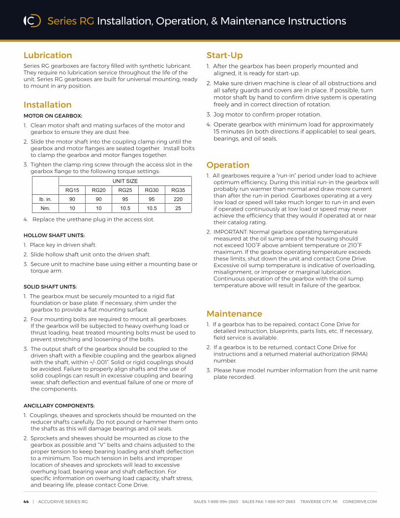
44 | ACCUDRIVE SERIES RG SALES: 1-888-994-2663 SALES FAX: 1-888-907-2663 TRAVERSE CITY, MI CONEDRIVE.COM
LubricationSeries RG gearboxes are factory filled with synthetic lubricant. They require no lubrication service throughout the life of the unit. Series RG gearboxes are built for universal mounting; ready to mount in any position.
InstallationMOTOR ON GEARBOX:
1. Clean motor shaft and mating surfaces of the motor and gearbox to ensure they are dust free.
2. Slide the motor shaft into the coupling clamp ring until the gearbox and motor flanges are seated together. Install bolts to clamp the gearbox and motor flanges together.
3. Tighten the clamp ring screw through the access slot in the gearbox flange to the following torque settings:
4. Replace the urethane plug in the access slot.
HOLLOW SHAFT UNITS:
1. Place key in driven shaft.2. Slide hollow shaft unit onto the driven shaft.3. Secure unit to machine base using either a mounting base or
torque arm.
SOLID SHAFT UNITS:
1. The gearbox must be securely mounted to a rigid flat foundation or base plate. If necessary, shim under the gearbox to provide a flat mounting surface.
2. Four mounting bolts are required to mount all gearboxes. If the gearbox will be subjected to heavy overhung load or thrust loading, heat treated mounting bolts must be used to prevent stretching and loosening of the bolts.
3. The output shaft of the gearbox should be coupled to the driven shaft with a flexible coupling and the gearbox aligned with the shaft, within +/-.001”. Solid or rigid couplings should be avoided. Failure to properly align shafts and the use of solid couplings can result in excessive coupling and bearing wear, shaft deflection and eventual failure of one or more of the components.
ANCILLARY COMPONENTS:
1. Couplings, sheaves and sprockets should be mounted on the reducer shafts carefully. Do not pound or hammer them onto the shafts as this will damage bearings and oil seals.
2. Sprockets and sheaves should be mounted as close to the gearbox as possible and “V” belts and chains adjusted to the proper tension to keep bearing loading and shaft deflection to a minimum. Too much tension in belts and improper location of sheaves and sprockets will lead to excessive overhung load, bearing wear and shaft deflection. For specific information on overhung load capacity, shaft stress, and bearing life, please contact Cone Drive.
Start-Up1. After the gearbox has been properly mounted and
aligned, it is ready for start-up.2. Make sure driven machine is clear of all obstructions and
all safety guards and covers are in place. If possible, turn motor shaft by hand to confirm drive system is operating freely and in correct direction of rotation.
3. Jog motor to confirm proper rotation.4. Operate gearbox with minimum load for approximately
15 minutes (in both directions if applicable) to seal gears, bearings, and oil seals.
Operation1. All gearboxes require a “run-in” period under load to achieve
optimum efficiency. During this initial run-in the gearbox will probably run warmer than normal and draw more current than after the run-in period. Gearboxes operating at a very low load or speed will take much longer to run-in and even if operated continuously at low load or speed may never achieve the efficiency that they would if operated at or near their catalog rating.
2. IMPORTANT: Normal gearbox operating temperature measured at the oil sump area of the housing should not exceed 100°F above ambient temperature or 210°F maximum. If the gearbox operating temperature exceeds these limits, shut down the unit and contact Cone Drive. Excessive oil sump temperature is indicative of overloading, misalignment, or improper or marginal lubrication. Continuous operation of the gearbox with the oil sump temperature above will result in failure of the gearbox.
Maintenance1. If a gearbox has to be repaired, contact Cone Drive for
detailed instruction, blueprints, parts lists, etc. If necessary, field service is available.
2. If a gearbox is to be returned, contact Cone Drive for instructions and a returned material authorization (RMA) number.
3. Please have model number information from the unit name plate recorded.
UNIT SIZE
RG15 RG20 RG25 RG30 RG35
lb. in. 90 90 95 95 220
Nm. 10 10 10.5 10.5 25
Series RG Installation, Operation, & Maintenance Instructions

CONE DRIVE | 45SALES: 1-888-994-2663 SALES FAX: 1-888-907-2663 TRAVERSE CITY, MI CONEDRIVE.COM
IMPORTANT: In any applications of Cone Drive Products where breakage, damage, disconnection, any other malfunction of any drive train component, or excessive wear could result in personal injury or property damage, a fail-safe device capable of stopping and holding the load in the event of such an occurrence must be incorporated after the drive train.
THE FOLLOWING INFORMATION IS FOR YOUR PROTECTION. DO NOT ATTEMPT TO INSTALL OR OPERATE THIS GEARBOX UNTIL ALL OF THESE INSTRUCTIONS ARE READ AND THOROUGHLY UNDERSTOOD.
SELF-LOCKINGIt is a common misconception that all worm gears are self-locking or non-overhauling. Actually, worm gear ratios up to 15:1 will overhaul quite freely. Ratios from 20:1 to 40:1 can generally be considered as overhauling with difficulty (particularly from rest). Ratios above 40:1 may or may not overhaul depending on loading, lubrication, and the amount of vibration present. Cone Drive cannot guarantee any worm gear ratio to be self-locking. There have been instances where single reduction ratios as high as 100:1 have overhauled. Therefore, it is not acceptable to rely on a worm gear to prevent movement in a system. Whenever a load must be stopped or held in place, a positive mechanical device must be incorporated into the system to prevent rotation of the gear set.
BACKDRIVING OR OVERHAULINGApplications such as wheel drives that require a brake on the motor or input shaft to decelerate a high inertial load require special attention to brake selection. Whenever possible, these applications should utilize freely overhauling ratios (15:1 or less). If self-locking ratios are used with a brake, the gear set can, under certain conditions, lock-up during decelerations and impose severe shock loading on the gearbox and driven equipment. Each reduction should be limited to 15:1 or less to allow the gearbox to overhaul. Contact Cone Drive for specific information on backdriving efficiency and brake selection.
RATINGS & SERVICE FACTORSThe horsepower or output torque capacity of this gearbox and the service factor (maximum allowable operating cycle) are documented in the product catalog. These values are not to be exceeded as overloading can result in gearbox failure. Exceeding the rating and duty cycle will void the warranty. Please contact Cone Drive with any questions regarding rating and service factors.
ALTERATIONDo not alter the gearbox without approval from Cone Drive.
OPERATION & REPAIRThis gearbox has moving mechanical components and may have connected electrical devices operating under high voltage. Operation and repair should only be done by qualified personnel.
PROTECTIVE GUARDINGCone Drive products are furnished without guard covers. It is the responsibility of the purchase or user to provide guards for all exposed shafting, couplings, sprockets, sheaves, belts, chains, clutches, and any other moving parts in accordance with current local, state, and federal requirements.
LOCK-OUT/TAG-OUTBefore servicing a gearbox, the main electrical disconnect or other input power sources must be moved to and locked in the off-position. The person performing the work should post on that disconnect a warning to others not to turn on the power. Loads on the input and output shafts should be disconnected prior to working on the gearbox.
GEARBOX SURFACE IS HOTIt is normal for the gearbox to operate at temperatures up to and exceeding 200°F. To prevent burns, proper personal protective equipment, guards, or shields should be provided by the purchaser or user to prevent personnel from touching the gearbox.
SAFETY PRECAUTIONS
Product Safety Page

46 | ACCUDRIVE SERIES RG SALES: 1-888-994-2663 SALES FAX: 1-888-907-2663 TRAVERSE CITY, MI CONEDRIVE.COM10282020
+1 888 994 2663 | [email protected] | conedrive.com | conetools.com
NORTH AMERICA | EUROPE | ASIA
GLOBAL LOCATIONS