Embed Size (px)
Citation preview


2
Contents
DO NOT REMOVE DS JOB NUMBER LABELS FROM FRAME OR LEAF FOR TRACEABILITY
Before you start
Door Set installation
Fixing positions
Fitting sidepanel into an installed frame
Fixing decorative hardware
3D adjustable hinge instructions
Sealing around the perimeter
Door restrictor instructions
Glazing instructions
Thermal movement definition and tolerances
3
5
7
8
9
10
12
13
14
19

3
Before you start
Do not remove existing door until you have checked:
These instructions must be read and completely understood before any work commences.
• The sizes are correct and you have everything as ordered• The paperwork to ensure it is the correct specification• Any damage to the door (do not install a damaged door)
• Tape measure• Hammer• Stanley knife• Crowbar• Chisel• Electric drill with hammer action• Screwdrivers (both Phillips and flat head)
• Silicone sealant gun• Saw• Rubber mallet• Spirit levels• 3mm allen key• 4mm allen key• 6mm socket spanner• T15 Torx bit
Health and Safety
Recommended tools
Care should be taken when handling the door - help should be sought due to it’s weight.
Avoid sharp edges
Keep electrical leads and cables away from sharp and abrasive surfaces and protect against tension and moisture. An RCD breaker should be used as per manufacturer’s instructions to protect from electric shocks.
Keep children and pets away from building operations.
All waste products should be disposed of correctly and safely.
4
Preparing the Opening
Removing the Existing Door
Door Alignment
Remove the existing door leaf.
To help reduce the damage to wall decorations and plaster, score around the perimeter of the frame with a craft knife. Saw through the jambs and remove. The best way to do this is by sawing diagonally in the centre and removing them in two sections.
Do not saw them all the way through as this can cause damage to the internal reveals or structure. If there is a chance this will happen, use a bearing block to protect the plaster and render, then lever the jambs away from the walls and complete the cuts.
Remove the top and bottom rails in the same way.
Once the door has been removed, ensure the opening is free from screws, nails, fillers and mastic.Repair as required in accordance with BPF recommendations.The opening should be complete before fitting the door.Check there’s a lintel or other load transferring structure fitted above the doorway.
The positioning of the door within the brickwork is vital to the correct functioning of the door.• Frame is square and plumb in both planes
• Door outerframe set back as far as possible to reduce exposure to elements
• Bridge the wall cavity
• Cover the DPC
• Frame is square and not twisted

5
Door set installation
Offer complete door unit into brickwork opening.
Hold frame into position using appropriate
size wedge packers. Packers must be located
adjacent to fixing positions to prevent distortion
of the outer frame when frame fixings are
tightened. Failure to adhere to this may result in
door function issues.
Spirit level (1.5m Long) should be used to ensure
jambs are square and plumb in all planes.
2
1
3

6
It is recommended that you remove the door
leaf from the hinges to make the outer frame
easier to fix into brickwork aperture. Once
square and plumb, fix as per instructions.
(See fixings & positions)
Pack the bottom of the door leaf at the leading
edge to assist getting square into outerframe.
Refer to separate hinge instructions on Page 10 if you have ordered other than Butt (fixed) Hinges
4
5

7
Fixing positions
Drilling
Fixings
Fixing Side Panel To Main Door Frame
These positions are for guidelines only.
Ensure fixings are into secure substrate.Recommended fixing positions are as follows:
Corner fixings: 150mm minimum and a maximum of 250mm from external corner.
Intermediate fixings: Centres not exceeding 600mm.
Transoms fixing: Should not be closer than 150mm from transom centre line and no greater than 250mm.
Alternative fixing may be required due to lintel location.
Drill holes through the frame as indicated (ensuring the holes are as recommended by the frame fixing manufacturer).
Secure the frame to the brickwork (NOT MORTAR) with suitable frame fixings. Ensure the fixing is secure and correctly positioned in the brickwork.
The outerframe should be secured into the brickwork using industry standard plastic sheathed frame fixings.
These should be a minimum of 100mm long and fixed into the masonry by a minimum of 50mm.
Tighten and secure all the fixings to ensure the frame is square.
Care should be taken not to over-tighten the frame fixings to avoid distortion of the frame.
Recommended fixings are plastic sheathed frame fixing bolts minimum length 8 x 100 mm.
Recommended fixing points are the same as fixing points into the brickwork above.Pre-drill fixing positions required for transom screw (SH01 4.8 x 65mm)Apply silicone to the entire length between the PVC-U profile and aluminium coupler on both faces.There should be a minimum of 4 fixings each side of the frame coupling profile.Ensure fixings are staggered to avoid collision on the opposite side of profile.

8
Fitting sidepanel (into an installed frame)
Inside
InsideInside Outside
Outside
Inside
Outside
Outside
‘CLICK’ ‘CLICK’
‘CLICK
’
Flush
Uneven
1 2
5 6
43
7 8 9
9
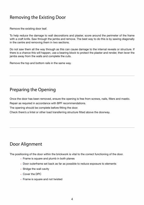
Fixing decorative hardware
NB: When the door has been fixed into position the operation of the door opening and locking mechanism must be checked to ensure uniform contact with weatherseals and correct function of handle/lock.
NB: Care should be taken when the fittings are positioned to ensure the security chain will function correctly.
NB: If your furniture selection is fixed handle for the Slam Lock (Winkhaus AV2), discard spring loaded plate and insert the supplied locking plate. Note the shorter spindle must be used.
Fixings
Fixing Security Chain
Fixing Decorative Numerals
To fit door handle set, locate spindle through square hole in lock mechanism. Align projecting pins on internal half of door handle set with pre-drilled holes in door slab.
Ensure handle spring washers are in position and secure using fixing screws supplied.
The security chain should be positioned into the desired location for ease of use (i.e. to suit the persons who will be required to use the device) Mark the fixing positions onto the door/frame using the pre-drilled holes in fittings as a template. Move the security chain and drill pilot holes in the marked positions, use the screws provided to secure.
Numerals should be located in the desired position on the composite door, when satisfied this is correct, the holes in the numerals should be used as a template to mark the required pilot holes to fix. Drill pilot holes and use the screws provided to secure to the door.

10
A
B
C
D
A
B
C
D
Frame plate
Slide plate
Socket screw (covered)
Hex pin (covered)
Hanging and removing the door
Remove the 2 screws that clamp side plate (B) to frame plate (A) to all three hinges
Carefully slide the door away from the frame plates.
Replace the door by reversing steps 1 and 2.
31 A B 2
A
B
3D adjustable hinge instructions
Tools required
An adjustment tool that combines both 6mm socket and 4mm Allen key is available from Door-Stop International.(part code TRO-ADJUSTMENT-KEY)
• Drill
• Suitable pozi drive bit
• Flat screw driver (for compression adjustment)
• 4mm allen Key
• 6mm socket spanner (for side-to-side adjustment)

11
Height
Side-to-side
Compression
C
1
A
B
Loosen the 2 screws that clamp side plate (B) to frame plate (A)
2
Lever the slide plate (B) with a screwdriver in the adjustment slot
Secure the screws in the side plate.
1
Remove the centre covers by hand.
2
C
With a 4mm allen key loosen the socket screws (C) by about 1/3 of a turn. Take care not to overtighten.
Lift and support the door to the required height whilst securing the socket screws. Replace the covers.
Repeat steps 1 and 2 of the height adjustment to one hinge at a time
2 D1
C
Carefully remove the top cap and with a 6mm socket spanner rotate the hex pin (D).
3
3
3
When in position secure the socket screw and replace the covers. Take care not to overtighten.
Adjustment instructions (adjust all three at once)

12
Sealing around the perimeter
Silicone sealant or similar suitable product should be used to seal around the perimeter of the newly installed composite door frame. Ensure that an adequate barrier is formed to prevent water ingress/air leakage.
NB: Care must be taken to ensure that the drainage slots are not blocked when sealing around the aluminium wheelchair threshold.

13
For outward opening doors
C
Fix leaf-side of the restrictor using the pre-drilled pilot hole at point A and one of the supplied screws.
Open door to the desired maximum opening angle.
Open the restrictor and locate it in the bead channel of the outer-frame.
Fix frame-side of the restrictor to the outer frame using the remaining fixing screws at points B & C.
A1
B4
2
3
Door restrictor instructions

14
If your composite door is unglazed, refer to the following guidelines
The following companies are recommended for the glazing materials you will need:
Cassette to glass and door = Clear silicon sealant (Premium+ 450 Builders Silicon – part code 5029347601355) from Everflex,Tel: 0113 240 3456, e-mail: [email protected]: http://www.everbuild.co.uk
Connecting bosses (or lugs) and self tapping screws supplied for each position. Glazing Panel supplier or purchased separately.
Lug for bosspositions
Connectingboss
Glazing instructions
Glazing Materials
Composite Door Glazing Method

15
Trim sealant nozzle to give approximately a 6mm bead.
Clean glazing panel prior to fitting and wipe down door. Ensure both components are fully dry before continuing.
Remove injection sprues from both cassettes prior to fitting. There may be a number on each cassette. They should easily break off by bending gently back and forth.
Apply the clear silicon sealant to the door edge and glass edge face of both cassettes. Pay attention to ensure the bead is continuous and complete. If necessary re-apply over thin areas (excess can be removed after fitting).
Sealant MUST be all round both cassettes.
Glass edge
Door edge
Sprue
Glazing Method

16
Position the external cassette on a flat surface. Ensure cassette is the same colour as the side it is being applied to. Position the door over cassette. Lower the door onto the cassette. Ensure frame is square in door.
Fit bosses to every boss position. The low part of the clip touches the glazing panel and the high point touches the door. Screw pinch tight using supplied self tapping screws.
Cassette and glazing panel should be tight.
Lower the glazing panel into cassette. Ensure it is the correct way round. Push down gently onto sealant.
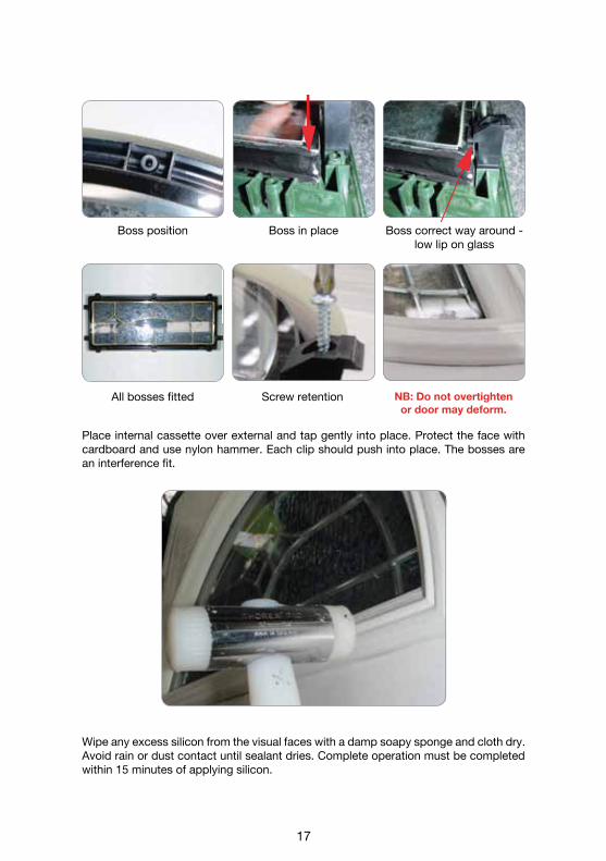
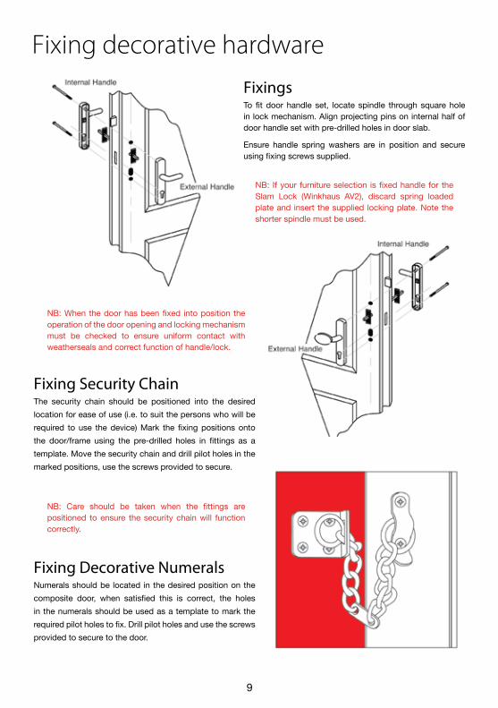
17
All bosses fitted Screw retention NB: Do not overtightenor door may deform.
Place internal cassette over external and tap gently into place. Protect the face with cardboard and use nylon hammer. Each clip should push into place. The bosses are an interference fit.
Wipe any excess silicon from the visual faces with a damp soapy sponge and cloth dry. Avoid rain or dust contact until sealant dries. Complete operation must be completed within 15 minutes of applying silicon.
Boss position Boss in place Boss correct way around - low lip on glass

18
Door-Stop International Ltd. Export Drive, Huthwaite, Notts. NG17 6AFTel: 01623 446336 Fax: 01623 553892
www.door-stop.co.uk
All information in this manual is provided for guidance only.Door-Stop International Ltd cannot be held responsible for the way in which the
information in this manual is interpreted.We reserve the right to alter specifications and descriptions without prior notice
as part of our policy of continual development.

19
Cut o
ut a
nd le
ave
for t
he h
omeo
wne
r
All composite slabs, as do UPVC and timber, experience thermal movement. The slab will recover to its flat plane, to a maximum bow of 3mm side to side and 5mm top to bottom, when the installation recommendations are applied (see below).
Slackening off the lock keeps will compensate for the movement of the slab within these tolerances.The hooks of the multipoint lock must be in compression with the inner edge of the pocket keep. If this does not happen the door may move to the inside of the property (towards the cold side) and give the impression the door is bowed. It is important to ensure the centre keep for the latch only allows the door to become flush with the inner face of the outer frame and not any tighter as this could also cause the door to appear bowed.
If the hooks on the multipoint lock are not thrown throughout the day and the centre keep setting is too tight, the top and bottom of the door will be in unsupported tension and will eventually stand proud of the inner face of the profile. This will make the hooks on the lock become stiff, as they cannot draw themselves into the hook keep. Protect your door from natural thermal distortion. Make sure the top and bottom locking points are engaged by pulling the handle up every time you shut the door.
If these points are not observed the warranties on the functionality and operation of the door could be affected.
Condensation issues are typically building ventilation related, not product related.
For further information, contact recognised trade organisations.
Thermal movement definition and tolerances
INSIDEOUTSIDE INSIDEOUTSIDEINSIDEOUTSIDE INSIDEOUTSIDE
VerticalDeflection of the slab inwards and outwards
from top to bottom.
Maximum bow permitted is 5mm
measured from the middle of the slab.
Maximum bow permitted is 3mmmeasured from the middle of the slab.
HorizontalDeflection of the slab inwards and
outwards from side to side.