Embed Size (px)
Citation preview
Applications Manual
9.1 Overview9.2 Efficiency and Dissipation power9.3 Thermal resistance9.4 Convection cooling9.5 Forced air cooling9.6 Notes on Thermal design
9.6.1 Baseplate temperature9.6.2 Heat sink mounting9.6.3 Installation of modules
9.7 Thermal design example9.8 Efficiency vs. Output current9.9 Heat sink size and Thermal resistance9.10 Thermal curves
9.10.1 Measuring environment9.10.2 Thermal curves
9. Thermal ConsiderationspageI-1I-1I-2I-3I-3I-3I-3I-4I-5I-6I-7I-12I-14I-14I-14
To ensure operation of power module, it is necessary to keep baseplate temperature within theallowable temperature limit. The reliability of the power module depends on the temperature ofthe baseplate. In order to obtain maximum reliability, keep the aluminum base plate temperaturelow.Proper thermal design makes higher MTBF, smaller size and lower costs.
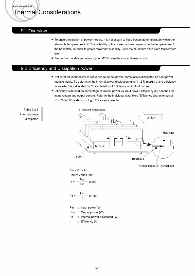
Not all of the input power is converted to output power, some loss is dissipated as heat powermodule inside. To determine the internal power dissipation, give 1 - 2 % margin of the efficiencyvalue which is calculated by Characteristics of Efficiency vs. Output current.Efficiency is defined as percentage of Output power vs Input power. Efficiency (E) depends oninput voltage and output current. Refer to the individual data. Here 'Efficiency characteristic ofCBS2004812' is shown in Fig.8.2.2 as an example.
Table 9.2.1Internal power
dissipated
Pin = Vin x IinPout = Vout x Iout
Pin : Input power (W)Pout : Output power (W)Pd : Internal power dissipated (W)η : Efficiency (%)
η = Pout
x 100Pin
Pd = 1 - η
x Poutη
I-1
2.1 Pin configuration9.2 Efficiency and Dissipation power
2.1 Pin configuration9.1 Overview
Ta (Ambient temperature)
Application Manual
Thermal Considerations
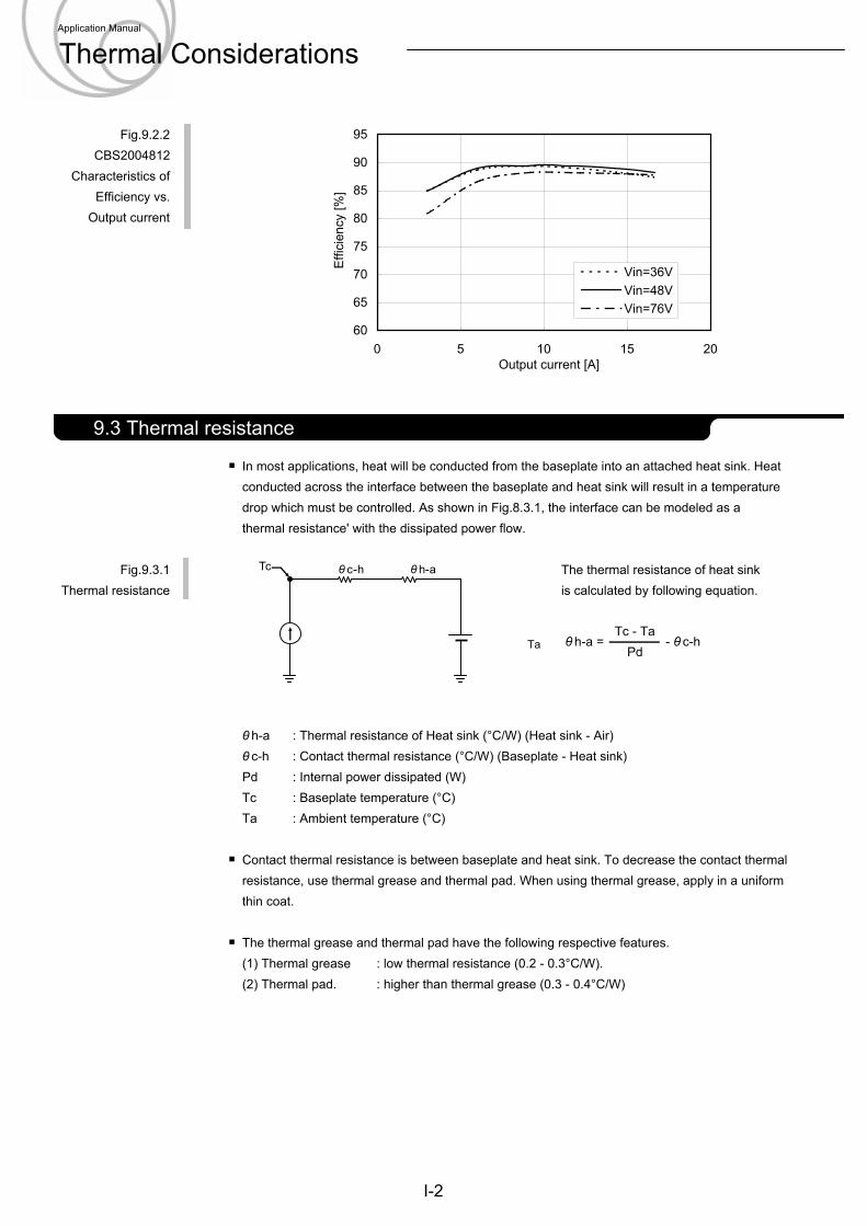
Fig.9.2.2CBS2004812
Characteristics ofEfficiency vs.
Output current
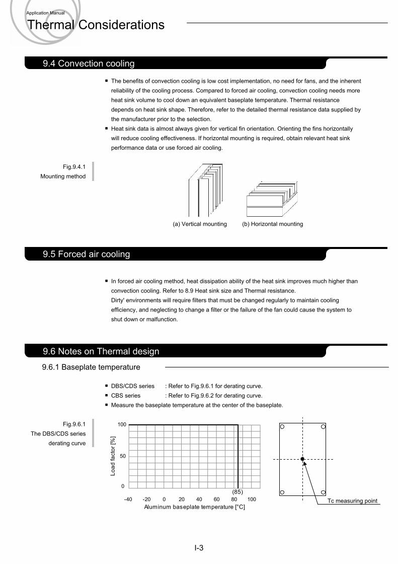
In most applications, heat will be conducted from the baseplate into an attached heat sink. Heatconducted across the interface between the baseplate and heat sink will result in a temperaturedrop which must be controlled. As shown in Fig.8.3.1, the interface can be modeled as athermal resistance' with the dissipated power flow.
Fig.9.3.1 The thermal resistance of heat sinkThermal resistance is calculated by following equation.
θ h-a : Thermal resistance of Heat sink (°C/W) (Heat sink - Air)θ c-h : Contact thermal resistance (°C/W) (Baseplate - Heat sink)Pd : Internal power dissipated (W)Tc : Baseplate temperature (°C)Ta : Ambient temperature (°C)
Contact thermal resistance is between baseplate and heat sink. To decrease the contact thermalresistance, use thermal grease and thermal pad. When using thermal grease, apply in a uniformthin coat.
The thermal grease and thermal pad have the following respective features.(1) Thermal grease : low thermal resistance (0.2 - 0.3°C/W).(2) Thermal pad. : higher than thermal grease (0.3 - 0.4°C/W)
θ h-a =Tc - Ta
- θ c-hPd
I-2
2.1 Pin configuration9.3 Thermal resistance
60
65
70
75
80
85
90
95
0 5 10 15 20Output current [A]
Effi
cien
cy [%
]
Vin=36VVin=48VVin=76V
Ta
Application Manual
Thermal Considerations
θ h-aθ c-hTc
The benefits of convection cooling is low cost implementation, no need for fans, and the inherentreliability of the cooling process. Compared to forced air cooling, convection cooling needs moreheat sink volume to cool down an equivalent baseplate temperature. Thermal resistancedepends on heat sink shape. Therefore, refer to the detailed thermal resistance data supplied bythe manufacturer prior to the selection.Heat sink data is almost always given for vertical fin orientation. Orienting the fins horizontallywill reduce cooling effectiveness. If horizontal mounting is required, obtain relevant heat sinkperformance data or use forced air cooling.
Fig.9.4.1Mounting method
(a) Vertical mounting (b) Horizontal mounting
In forced air cooling method, heat dissipation ability of the heat sink improves much higher thanconvection cooling. Refer to 8.9 Heat sink size and Thermal resistance.Dirty' environments will require filters that must be changed regularly to maintain coolingefficiency, and neglecting to change a filter or the failure of the fan could cause the system toshut down or malfunction.
9.6.1 Baseplate temperature
DBS/CDS series : Refer to Fig.9.6.1 for derating curve.CBS series : Refer to Fig.9.6.2 for derating curve.Measure the baseplate temperature at the center of the baseplate.
Fig.9.6.1The DBS/CDS series
derating curve
I-3
2.1 Pin configuration9.6 Notes on Thermal design
2.1 Pin configuration9.5 Forced air cooling
2.1 Pin configuration9.4 Convection cooling
Tc measuring point
Application Manual
Thermal Considerations
0 20-40 -20 80 100Aluminum baseplate temperature [°C]
Load
fact
or [%
]
40 60
50
0
100
(85)
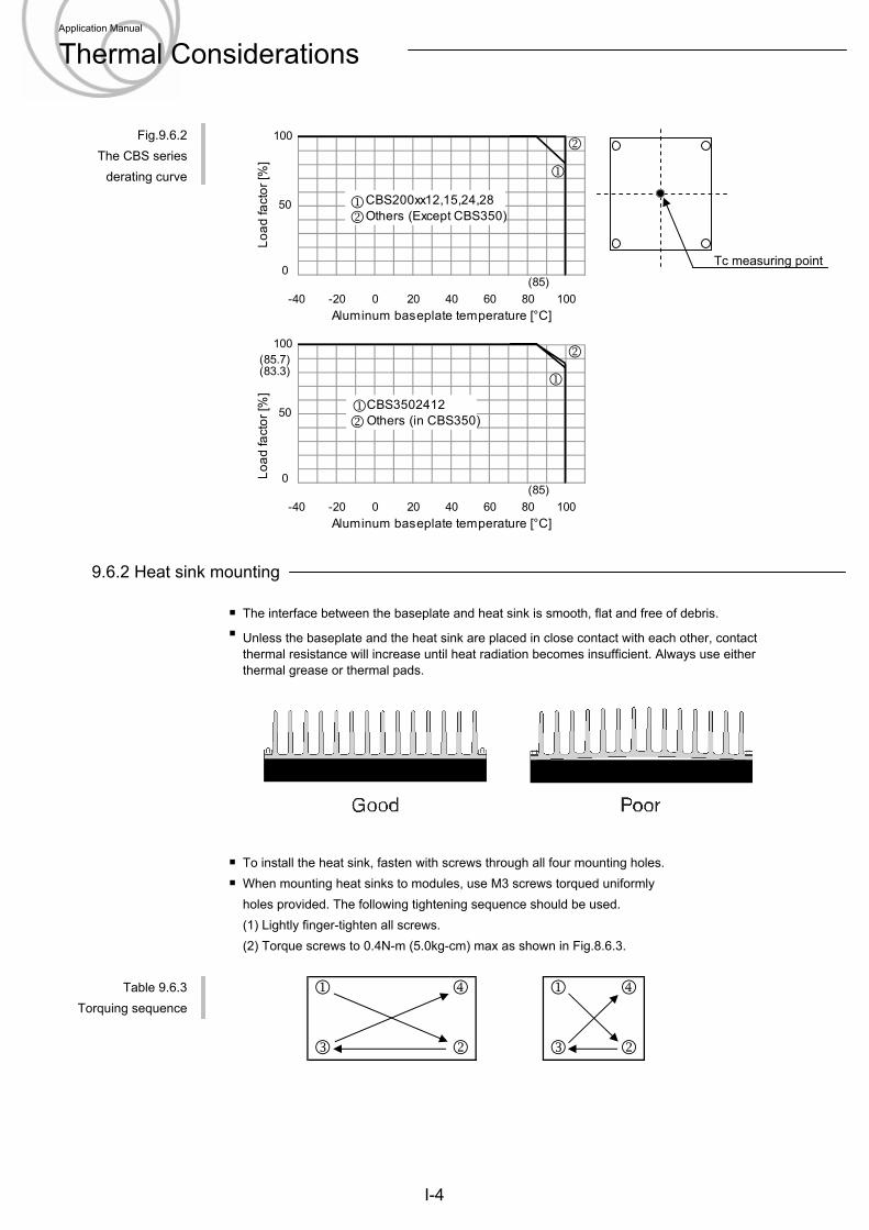
Fig.9.6.2The CBS series
derating curve
9.6.2 Heat sink mounting
The interface between the baseplate and heat sink is smooth, flat and free of debris.
To install the heat sink, fasten with screws through all four mounting holes.When mounting heat sinks to modules, use M3 screws torqued uniformlyholes provided. The following tightening sequence should be used.(1) Lightly finger-tighten all screws.(2) Torque screws to 0.4N-m (5.0kg-cm) max as shown in Fig.8.6.3.
Table 9.6.3Torquing sequence
Unless the baseplate and the heat sink are placed in close contact with each other, contactthermal resistance will increase until heat radiation becomes insufficient. Always use eitherthermal grease or thermal pads.
1 4 1 4
3 2 3 2
I-4
Tc measuring point
Application Manual
Thermal Considerations
100
50
-40 0 20 80 10040 60
Load
fact
or [%
]
Aluminum baseplate temperature [°C]-20
0
1(85.7)(83.3)
CBS35024121Others (in CBS350)2
2
(85)
-40 0 20
0
1008040 60
100
50
Load
fact
or [%
]
Aluminum baseplate temperature [°C]-20
2
CBS200xx12,15,24,281Others (Except CBS350)2
1
(85)
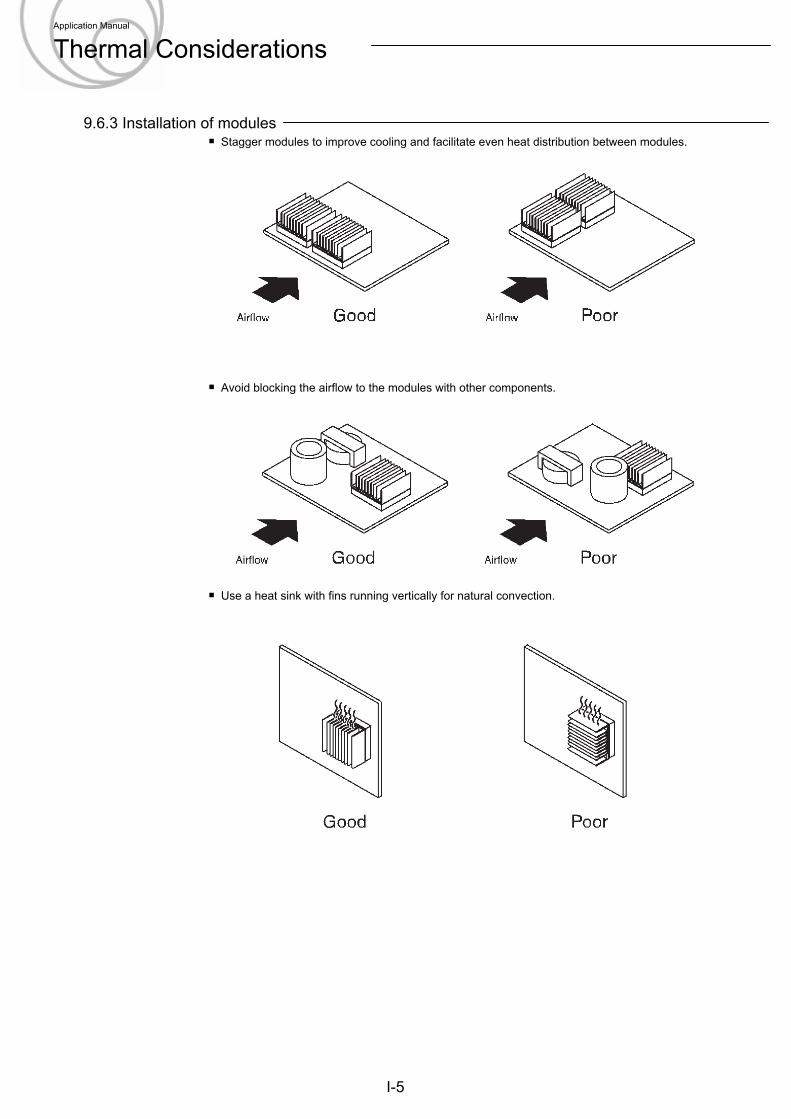
9.6.3 Installation of modulesStagger modules to improve cooling and facilitate even heat distribution between modules.
Avoid blocking the airflow to the modules with other components.
Use a heat sink with fins running vertically for natural convection.
I-5
Airflow
Application Manual
Thermal Considerations
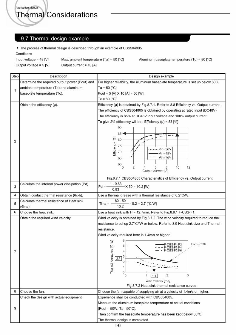
The process of thermal design is described through an example of CBS504805.ConditionsInput voltage = 48 [V] Max. ambient temperature (Ta) = 50 [°C] Aluminum baseplate temperature (Tc) = 80 [°C]Output voltage = 5 [V] Output current = 10 [A]
Determine the required output power (Pout) and For higher reliability, the aluminum baseplate temperature is set up below 80C.ambient temperature (Ta) and aluminum Ta = 50 [°C]baseplate temperature (Tc). Pout = 5 [V] X 10 [A] = 50 [W]
Tc = 80 [°C]Obtain the efficiency (μ). Efficiency (μ) is obtained by Fig.8.7.1. Refer to 8.8 Efficiency vs. Output current.
The efficiency of CBS504805 is obtained by operating at rated input (DC48V).The efficiency is 85% at DC48V input voltage and 100% output current.To give 2% efficiency will be : Efficiency (μ) = 83 [%]
Fig.8.7.1 CBS504805 Characteristics of Efficiency vs. Output currentCalculate the internal power dissipation (Pd).
Obtain contact thermal resistance (θc-h). Use a thermal grease with a thermal resistance of 0.2°C/W.Calculate thermal resistance of Heat sink(θh-a).Choose the heat sink. Use a heat sink with H = 12.7mm. Refer to Fig.8.9.1 F-CBS-F1.Obtain the required wind velocity. Wind velocity is obtained by Fig.8.7.2. The wind velocity required to reduce the
resistance to set up 2.7°C//W or below. Refer to 8.9 Heat sink size and Thermalresistance.Wind velocity required here is 1.4m/s or higher.
Choose the fan. Choose the fan capable of supplying air at a velocity of 1.4m/s or higher.Check the design with actual equipment. Experience shall be conducted with CBS504805.
Measure the aluminum baseplate temperature at actual conditions (Pout = 50W, Ta= 50°C).Then confirm the baseplate temperature has been kept below 80°C.The thermal design is completed.
Step Description Design example
1
2
3 Pd =1 - 0.83
X 50 = 10.2 [W]0.83
4
5 Th-a =80 - 50
- 0.2 = 2.7 [°C/W]10.2
6
7
Fig.8.7.2 Heat sink thermal resistance curves8
9
I-6
2.1 Pin configuration9.7 Thermal design example
Application Manual
Thermal Considerations
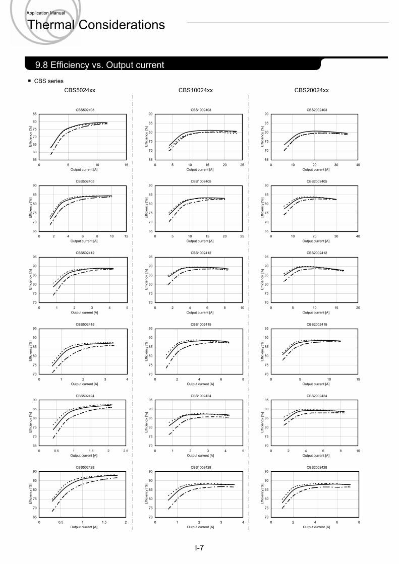
CBS seriesCBS5024xx CBS10024xx CBS20024xx
I-7
2.1 Pin configuration9.8 Efficiency vs. Output current
CBS502403
55
60
65
70
75
80
85
0 5 10 15Output current [A]
Effi
cien
cy [%
]
CBS502405
65
70
75
80
85
90
0 2 4 6 8 10 12Output current [A]
Effi
cien
cy [%
]
CBS502412
70
75
80
85
90
95
0 1 2 3 4 5Output current [A]
Effi
cien
cy [%
]
CBS502415
70
75
80
85
90
95
0 1 2 3 4Output current [A]
Effi
cien
cy [%
]
CBS502424
65
70
75
80
85
90
0 0.5 1 1.5 2 2.5Output current [A]
Effi
cien
cy [%
]
CBS502428
65
70
75
80
85
90
0 0.5 1 1.5 2Output current [A]
Effi
cien
cy [%
]
CBS1002403
65
70
75
80
85
90
0 5 10 15 20 25Output current [A]
Effi
cien
cy [%
]
CBS1002405
65
70
75
80
85
90
0 5 10 15 20 25Output current [A]
Effi
cien
cy [%
]
CBS1002412
70
75
80
85
90
95
0 2 4 6 8 10Output current [A]
Effi
cien
cy [%
]
CBS1002415
70
75
80
85
90
95
0 2 4 6 8Output current [A]
Effi
cien
cy [%
]
CBS1002424
70
75
80
85
90
95
0 1 2 3 4 5Output current [A]
Effi
cien
cy [%
]
CBS1002428
70
75
80
85
90
95
0 1 2 3 4Output current [A]
Effi
cien
cy [%
]
CBS2002403
65
70
75
80
85
90
0 10 20 30 40Output current [A]
Effi
cien
cy [%
]
CBS2002405
65
70
75
80
85
90
0 10 20 30 40Output current [A]
Effi
cien
cy [%
]
CBS2002412
70
75
80
85
90
95
0 5 10 15 20Output current [A]
Effi
cien
cy [%
]
CBS2002415
70
75
80
85
90
95
0 5 10 15Output current [A]
Effi
cien
cy [%
]
CBS2002424
70
75
80
85
90
95
0 2 4 6 8 10Output current [A]
Effi
cien
cy [%
]
CBS2002428
70
75
80
85
90
95
0 2 4 6 8Output current [A]
Effi
cien
cy [%
]
Application Manual
Thermal Considerations
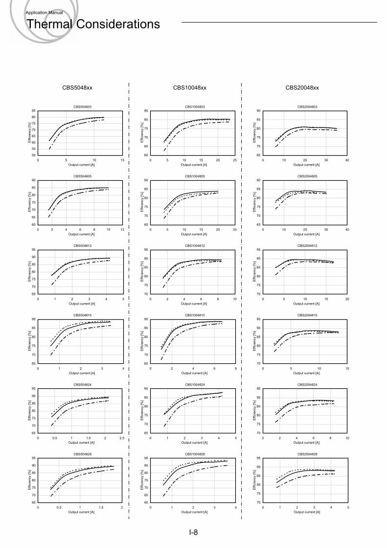
CBS5048xx CBS10048xx CBS20048xx
I-8
CBS504803
50
55
60
65
70
75
80
85
0 5 10 15Output current [A]
Effi
cien
cy [%
]
CBS504805
60
65
70
75
80
85
90
0 2 4 6 8 10 12Output current [A]
Effi
cien
cy [%
]
CBS504812
65
70
75
80
85
90
95
0 1 2 3 4 5Output current [A]
Effi
cien
cy [%
]
CBS504815
65
70
75
80
85
90
0 1 2 3 4Output current [A]
Effi
cien
cy [%
]
CBS504824
65
70
75
80
85
90
95
0 0.5 1 1.5 2 2.5Output current [A]
Effi
cien
cy [%
]
CBS504828
65
70
75
80
85
90
95
0 0.5 1 1.5 2Output current [A]
Effi
cien
cy [%
]
CBS1004803
60
65
70
75
80
85
0 5 10 15 20 25Output current [A]
Effi
cien
cy [%
]
CBS1004805
65
70
75
80
85
90
0 5 10 15 20 25Output current [A]
Effi
cien
cy [%
]
CBS1004812
70
75
80
85
90
95
0 2 4 6 8 10Output current [A]
Effi
cien
cy [%
]
CBS1004815
65
70
75
80
85
90
0 2 4 6 8Output current [A]
Effi
cien
cy [%
]
CBS1004824
65
70
75
80
85
90
0 1 2 3 4 5Output current [A]
Effi
cien
cy [%
]
CBS1004828
60
65
70
75
80
85
90
0 1 2 3 4Output current [A]
Effi
cien
cy [%
]
CBS2004803
65
70
75
80
85
90
0 10 20 30 40Output current [A]
Effi
cien
cy [%
]
CBS2004805
65
70
75
80
85
90
0 10 20 30 40Output current [A]
Effi
cien
cy [%
]
CBS2004812
70
75
80
85
90
95
0 5 10 15 20Output current [A]
Effi
cien
cy [%
]
CBS2004815
70
75
80
85
90
95
0 5 10 15Output current [A]
Effi
cien
cy [%
]
CBS2004824
70
75
80
85
90
95
0 2 4 6 8 10Output current [A]
Effi
cien
cy [%
]
CBS2004828
70
75
80
85
90
95
0 1 2 3 4 5Output current [A]
Effi
cien
cy [%
]
Application Manual
Thermal Considerations
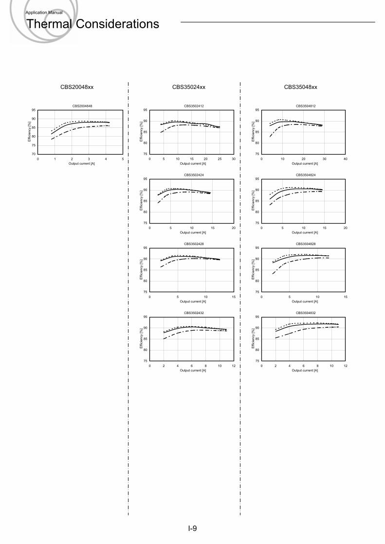
CBS20048xx CBS35024xx CBS35048xx
I-9
CBS2004848
70
75
80
85
90
95
0 1 2 3 4 5Output current [A]
Effi
cien
cy [%
]
CBS3502412
75
80
85
90
95
0 5 10 15 20 25 30Output current [A]
Effi
cien
cy [%
]
CBS3502424
75
80
85
90
95
0 5 10 15 20Output current [A]
Effi
cien
cy [%
]
CBS3502428
75
80
85
90
95
0 5 10 15Output current [A]
Effi
cien
cy [%
]
CBS3502432
75
80
85
90
95
0 2 4 6 8 10 12Output current [A]
Effi
cien
cy [%
]
CBS3504812
75
80
85
90
95
0 10 20 30 40Output current [A]
Effi
cien
cy [%
]
CBS3504824
75
80
85
90
95
0 5 10 15 20Output current [A]
Effi
cien
cy [%
]
CBS3504828
75
80
85
90
95
0 5 10 15Output current [A]
Effi
cien
cy [%
]
CBS3504832
75
80
85
90
95
0 2 4 6 8 10 12Output current [A]
Effi
cien
cy [%
]
Application Manual
Thermal Considerations
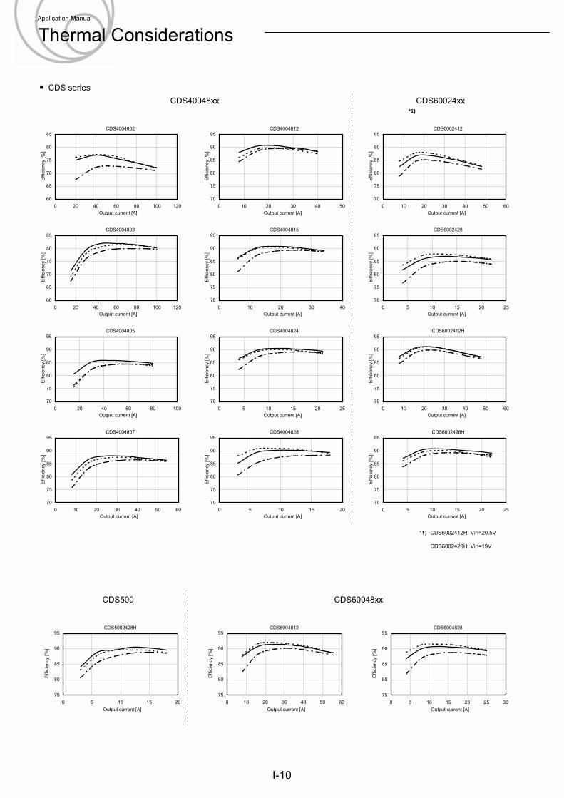
CDS series
*1) CDS6002412H: Vin=20.5V
CDS6002428H: Vin=19V
CDS40048xx CDS60024xx
CDS500 CDS60048xx
I-10
CDS5002428H
75
80
85
90
95
0 5 10 15 20Output current [A]
Effi
cien
cy [%
]
*1)
CDS4004802
60
65
70
75
80
85
0 20 40 60 80 100 120Output current [A]
Effi
cien
cy [%
]
CDS4004803
60
65
70
75
80
85
0 20 40 60 80 100 120Output current [A]
Effi
cien
cy [%
]
CDS4004805
70
75
80
85
90
95
0 20 40 60 80 100Output current [A]
Effi
cien
cy [%
]
CDS4004807
70
75
80
85
90
95
0 10 20 30 40 50 60Output current [A]
Effi
cien
cy [%
]
CDS4004812
70
75
80
85
90
95
0 10 20 30 40 50Output current [A]
Effi
cien
cy [%
]
CDS4004815
70
75
80
85
90
95
0 10 20 30 40Output current [A]
Effi
cien
cy [%
]
CDS4004824
70
75
80
85
90
95
0 5 10 15 20 25Output current [A]
Effi
cien
cy [%
]
CDS4004828
70
75
80
85
90
95
0 5 10 15 20Output current [A]
Effi
cien
cy [%
]
CDS6002412
70
75
80
85
90
95
0 10 20 30 40 50 60Output current [A]
Effi
cien
cy [%
]
CDS6002428
70
75
80
85
90
95
0 5 10 15 20 25Output current [A]
Effi
cien
cy [%
]
CDS6002412H
70
75
80
85
90
95
0 10 20 30 40 50 60Output current [A]
Effi
cien
cy [%
]
CDS6002428H
70
75
80
85
90
95
0 5 10 15 20 25Output current [A]
Effi
cien
cy [%
]
CDS6004812
75
80
85
90
95
0 10 20 30 40 50 60Output current [A]
Effi
cien
cy [%
]
CDS6004828
75
80
85
90
95
0 5 10 15 20 25 30Output current [A]
Effi
cien
cy [%
]
Application Manual
Thermal Considerations
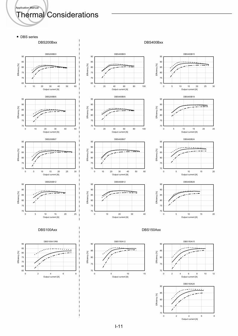
DBS seriesDBS200Bxx DBS400Bxx
DBS100Axx DBS150Axx
I-11
DBS200B03
65
70
75
80
85
90
0 10 20 30 40 50 60Output current [A]
Effi
cien
cy [%
]
DBS200B05
70
75
80
85
90
95
0 10 20 30 40 50Output current [A]
Effi
cien
cy [%
]
DBS200B07
70
75
80
85
90
95
0 5 10 15 20 25 30Output current [A]
Effi
cien
cy [%
]
DBS200B12
70
75
80
85
90
95
0 5 10 15 20 25Output current [A]
Effi
cien
cy [%
]
DBS400B03
65
70
75
80
85
90
0 20 40 60 80 100Output current [A]
Effi
cien
cy [%
]
DBS400B05
70
75
80
85
90
95
0 20 40 60 80 100Output current [A]
Effi
cien
cy [%
]
DBS400B07
70
75
80
85
90
95
0 10 20 30 40 50 60Output current [A]
Effi
cien
cy [%
]
DBS400B12
70
75
80
85
90
95
0 10 20 30 40Output current [A]
Effi
cien
cy [%
]
DBS400B15
70
75
80
85
90
95
0 5 10 15 20 25 30Output current [A]
Effi
cien
cy [%
]
DBS400B18
70
75
80
85
90
95
0 5 10 15 20 25Output current [A]
Effi
cien
cy [%
]
DBS400B24
70
75
80
85
90
95
0 5 10 15 20Output current [A]
Effi
cien
cy [%
]
DBS400B28
70
75
80
85
90
95
0 5 10 15 20Output current [A]
Effi
cien
cy [%
]
DBS100A13R8
60
65
70
75
80
85
90
0 2 4 6 8Output current [A]
Effi
cien
cy [%
]
DBS150A12
70
75
80
85
90
0 5 10 15Output current [A]
Effi
cien
cy [%
]
DBS150A15
70
75
80
85
90
0 2 4 6 8 10 12Output current [A]
Effi
cien
cy [%
]
DBS150A24
70
75
80
85
90
0 2 4 6 8Output current [A]
Effi
cien
cy [%
]
Application Manual
Thermal Considerations
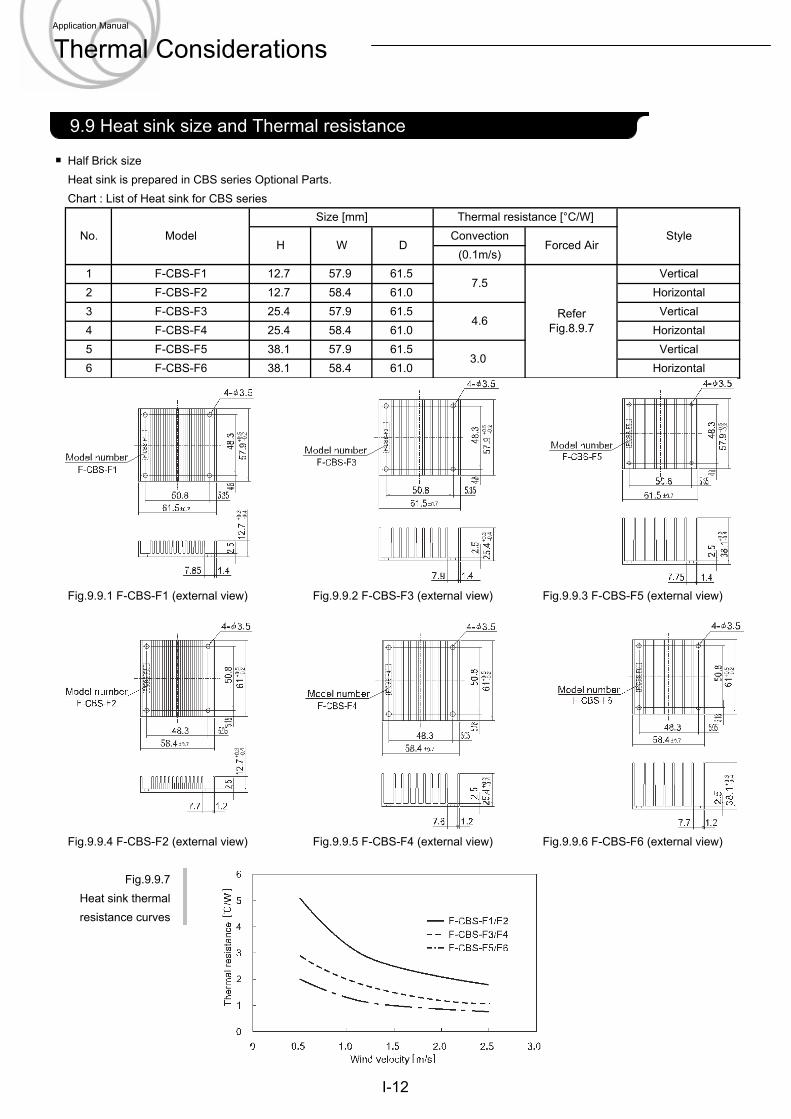
Half Brick sizeHeat sink is prepared in CBS series Optional Parts.Chart : List of Heat sink for CBS series
Fig.9.9.1 F-CBS-F1 (external view) Fig.9.9.2 F-CBS-F3 (external view) Fig.9.9.3 F-CBS-F5 (external view)
Fig.9.9.4 F-CBS-F2 (external view) Fig.9.9.5 F-CBS-F4 (external view) Fig.9.9.6 F-CBS-F6 (external view)
Fig.9.9.7Heat sink thermalresistance curves
No. ModelSize [mm] Thermal resistance [°C/W]
StyleH W D
ConvectionForced Air
(0.1m/s)1 F-CBS-F1 12.7 57.9 61.5
7.5
ReferFig.8.9.7
3
Vertical2 F-CBS-F2 12.7 58.4 61.0 Horizontal
Vertical4 F-CBS-F4 25.4 58.4 61.0 Horizontal
F-CBS-F3 25.4 57.9
F-CBS-F5 38.1 57.9
4.661.5
61.53.0
Vertical6 F-CBS-F6 38.1 58.4 61.0 Horizontal5
I-12
2.1 Pin configuration9.9 Heat sink size and Thermal resistance
Application Manual
Thermal Considerations
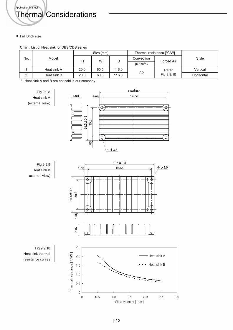
Full Brick size
Chart : List of Heat sink for DBS/CDS series
* Heat sink A and B are not sold in our company.
Fig.9.9.8Heat sink A
(external view)
Fig.9.9.9Heat sink B
external view)
Fig.9.9.10Heat sink thermalresistance curves
No. ModelSize [mm] Thermal resistance [°C/W]
StyleH W D
ConvectionForced Air
(0.1m/s)1 Heat sink A 20.0 60.5 116.0
7.5 ReferFig.8.9.10
Vertical2 Heat sink B 20.0 60.5 116.0 Horizontal
I-13
Application Manual
Thermal Considerations
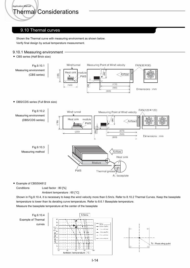
Shown the Thermal curve with measuring environment as shown below.Verify final design by actual temperature measurement.
9.10.1 Measuring environmentCBS series (Half Brick size)
Fig.9.10.1Measuring environment
(CBS series)
DBS/CDS series (Full Brick size)
Fig.9.10.2Measuring environment
(DBS/CDS series)
Fig.9.10.3Measuring method
Example of CBS504812Conditions Load factor : 80 [%]
Ambient temperature : 60 [°C]Shown in Fig.8.10.4, it is necessary to keep the wind velocity more than 0.5m/s. Refer to 8.10.2 Thermal Curves. Keep the baseplatetemperature is lower than its derating curve temperature. Refer to 8.6.1 Baseplate temperature.Measure the baseplate temperature at the center of the baseplate
Fig.9.10.4Example of Thermal
curves
I-14
2.1 Pin configuration9.10 Thermal curves
Application Manual
Thermal Considerations
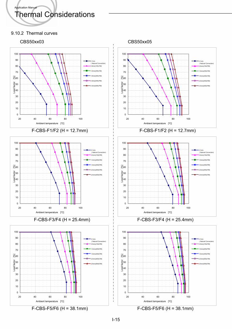
CBS50xx03 CBS50xx05
F-CBS-F1/F2 (H = 12.7mm) F-CBS-F1/F2 (H = 12.7mm)
9.10.2 Thermal curves
F-CBS-F3/F4 (H = 25.4mm) F-CBS-F3/F4 (H = 25.4mm)
F-CBS-F5/F6 (H = 38.1mm) F-CBS-F5/F6 (H = 38.1mm)
I-15
0
10
20
30
40
50
60
70
80
90
100
20 40 60 80 100
Ambient temperature [℃]
Load
fact
or
[%]
0.1m/s(Natural Convection)0.5m/s(100LFM)
1.0m/s(200LFM)
1.5m/s(300LFM)
2.0m/s(400LFM)
2.5m/s(500LFM)
0
10
20
30
40
50
60
70
80
90
100
20 40 60 80 100
Ambient temperature [℃]
Load
fact
or
[%]
0.1m/s(Natural Convection)0.5m/s(100LFM)
1.0m/s(200LFM)
1.5m/s(300LFM)
2.0m/s(400LFM)
2.5m/s(500LFM)
0
10
20
30
40
50
60
70
80
90
100
20 40 60 80 100
Ambient temperature [℃]Lo
ad fa
ctor
[%
]
0.1m/s(Natural Convection)0.5m/s(100LFM)
1.0m/s(200LFM)
1.5m/s(300LFM)
2.0m/s(400LFM)
2.5m/s(500LFM)
0
10
20
30
40
50
60
70
80
90
100
20 40 60 80 100
Ambient temperature [℃]
Load
fact
or
[%]
0.1m/s(Natural Convection)0.5m/s(100LFM)
1.0m/s(200LFM)
1.5m/s(300LFM)
2.0m/s(400LFM)
2.5m/s(500LFM)
0
10
20
30
40
50
60
70
80
90
100
20 40 60 80 100
Ambient temperature [℃]
Load
fact
or
[%]
0.1m/s(Natural Convection)0.5m/s(100LFM)
1.0m/s(200LFM)
1.5m/s(300LFM)
2.0m/s(400LFM)
2.5m/s(500LFM)
0
10
20
30
40
50
60
70
80
90
100
20 40 60 80 100
Ambient temperature [℃]
Load
fact
or
[%]
0.1m/s(Natural Convection)0.5m/s(100LFM)
1.0m/s(200LFM)
1.5m/s(300LFM)
2.0m/s(400LFM)
2.5m/s(500LFM)
Application Manual
Thermal Considerations
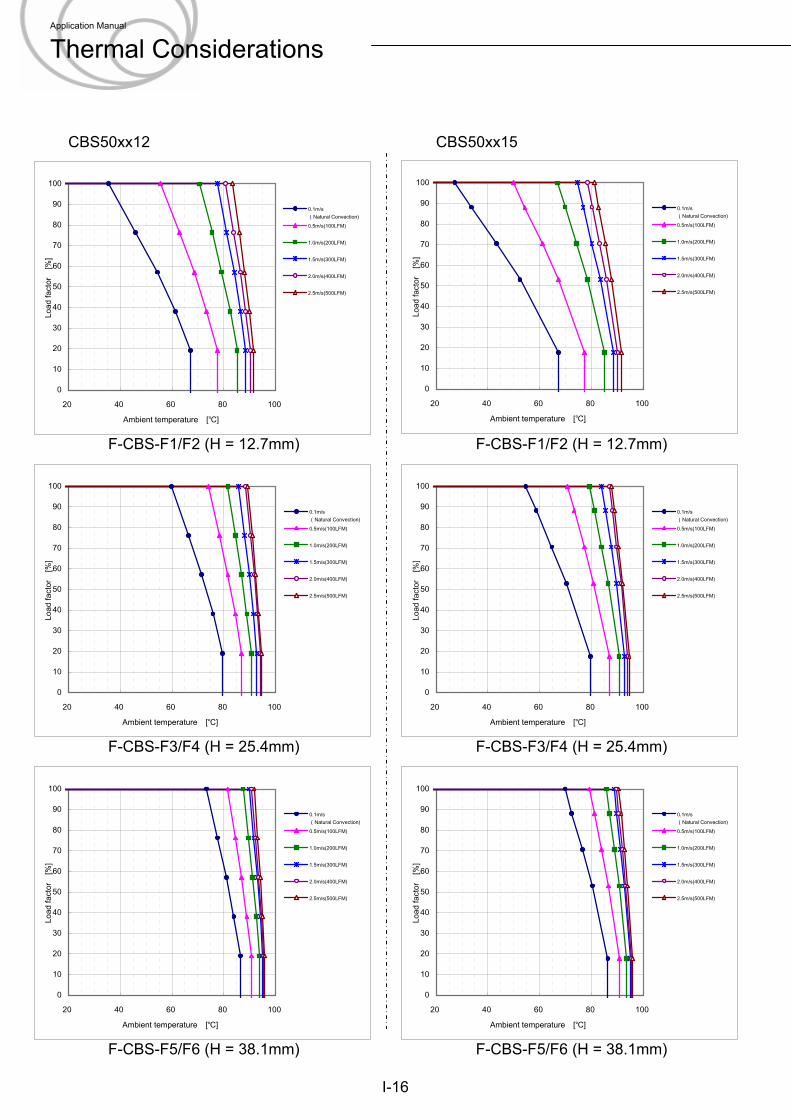
CBS50xx12 CBS50xx15
I-16
F-CBS-F5/F6 (H = 38.1mm) F-CBS-F5/F6 (H = 38.1mm)
F-CBS-F1/F2 (H = 12.7mm) F-CBS-F1/F2 (H = 12.7mm)
F-CBS-F3/F4 (H = 25.4mm) F-CBS-F3/F4 (H = 25.4mm)
0
10
20
30
40
50
60
70
80
90
100
20 40 60 80 100
Ambient temperature [℃]
Load
fact
or
[%]
0.1m/s(Natural Convection)0.5m/s(100LFM)
1.0m/s(200LFM)
1.5m/s(300LFM)
2.0m/s(400LFM)
2.5m/s(500LFM)
0
10
20
30
40
50
60
70
80
90
100
20 40 60 80 100
Ambient temperature [℃]
Load
fact
or
[%]
0.1m/s(Natural Convection)0.5m/s(100LFM)
1.0m/s(200LFM)
1.5m/s(300LFM)
2.0m/s(400LFM)
2.5m/s(500LFM)
0
10
20
30
40
50
60
70
80
90
100
20 40 60 80 100
Ambient temperature [℃]Lo
ad fa
ctor
[%
]
0.1m/s(Natural Convection)0.5m/s(100LFM)
1.0m/s(200LFM)
1.5m/s(300LFM)
2.0m/s(400LFM)
2.5m/s(500LFM)
0
10
20
30
40
50
60
70
80
90
100
20 40 60 80 100
Ambient temperature [℃]
Load
fact
or
[%]
0.1m/s(Natural Convection)0.5m/s(100LFM)
1.0m/s(200LFM)
1.5m/s(300LFM)
2.0m/s(400LFM)
2.5m/s(500LFM)
0
10
20
30
40
50
60
70
80
90
100
20 40 60 80 100
Ambient temperature [℃]
Load
fact
or
[%]
0.1m/s(Natural Convection)0.5m/s(100LFM)
1.0m/s(200LFM)
1.5m/s(300LFM)
2.0m/s(400LFM)
2.5m/s(500LFM)
0
10
20
30
40
50
60
70
80
90
100
20 40 60 80 100
Ambient temperature [℃]
Load
fact
or
[%]
0.1m/s(Natural Convection)0.5m/s(100LFM)
1.0m/s(200LFM)
1.5m/s(300LFM)
2.0m/s(400LFM)
2.5m/s(500LFM)
Application Manual
Thermal Considerations
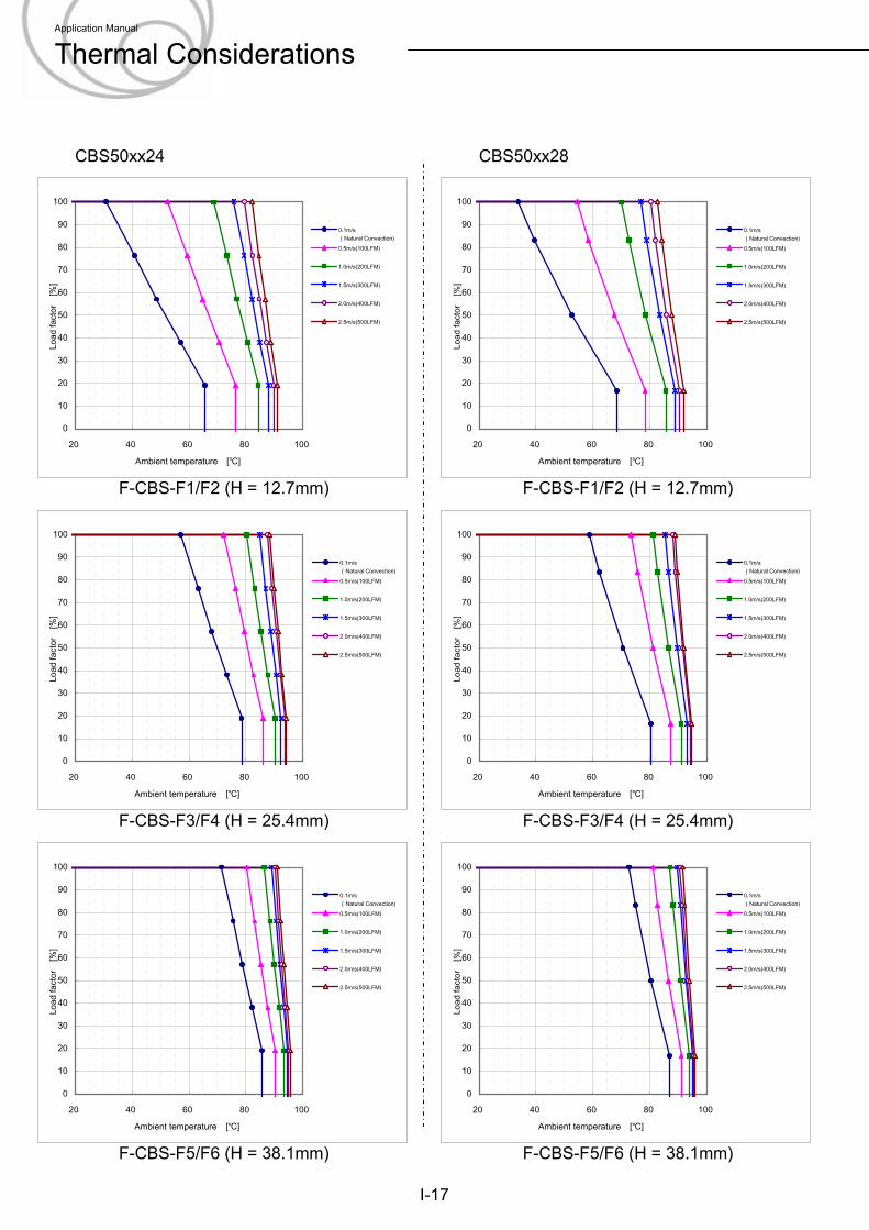
CBS50xx24 CBS50xx28
F-CBS-F1/F2 (H = 12.7mm) F-CBS-F1/F2 (H = 12.7mm)
F-CBS-F3/F4 (H = 25.4mm) F-CBS-F3/F4 (H = 25.4mm)
F-CBS-F5/F6 (H = 38.1mm) F-CBS-F5/F6 (H = 38.1mm)
I-17
0
10
20
30
40
50
60
70
80
90
100
20 40 60 80 100
Ambient temperature [℃]
Load
fact
or
[%]
0.1m/s(Natural Convection)0.5m/s(100LFM)
1.0m/s(200LFM)
1.5m/s(300LFM)
2.0m/s(400LFM)
2.5m/s(500LFM)
0
10
20
30
40
50
60
70
80
90
100
20 40 60 80 100
Ambient temperature [℃]
Load
fact
or
[%]
0.1m/s(Natural Convection)0.5m/s(100LFM)
1.0m/s(200LFM)
1.5m/s(300LFM)
2.0m/s(400LFM)
2.5m/s(500LFM)
0
10
20
30
40
50
60
70
80
90
100
20 40 60 80 100
Ambient temperature [℃]Lo
ad fa
ctor
[%
]
0.1m/s(Natural Convection)0.5m/s(100LFM)
1.0m/s(200LFM)
1.5m/s(300LFM)
2.0m/s(400LFM)
2.5m/s(500LFM)
0
10
20
30
40
50
60
70
80
90
100
20 40 60 80 100
Ambient temperature [℃]
Load
fact
or
[%]
0.1m/s(Natural Convection)0.5m/s(100LFM)
1.0m/s(200LFM)
1.5m/s(300LFM)
2.0m/s(400LFM)
2.5m/s(500LFM)
0
10
20
30
40
50
60
70
80
90
100
20 40 60 80 100
Ambient temperature [℃]
Load
fact
or
[%]
0.1m/s(Natural Convection)0.5m/s(100LFM)
1.0m/s(200LFM)
1.5m/s(300LFM)
2.0m/s(400LFM)
2.5m/s(500LFM)
0
10
20
30
40
50
60
70
80
90
100
20 40 60 80 100
Ambient temperature [℃]
Load
fact
or
[%]
0.1m/s(Natural Convection)0.5m/s(100LFM)
1.0m/s(200LFM)
1.5m/s(300LFM)
2.0m/s(400LFM)
2.5m/s(500LFM)
Application Manual
Thermal Considerations
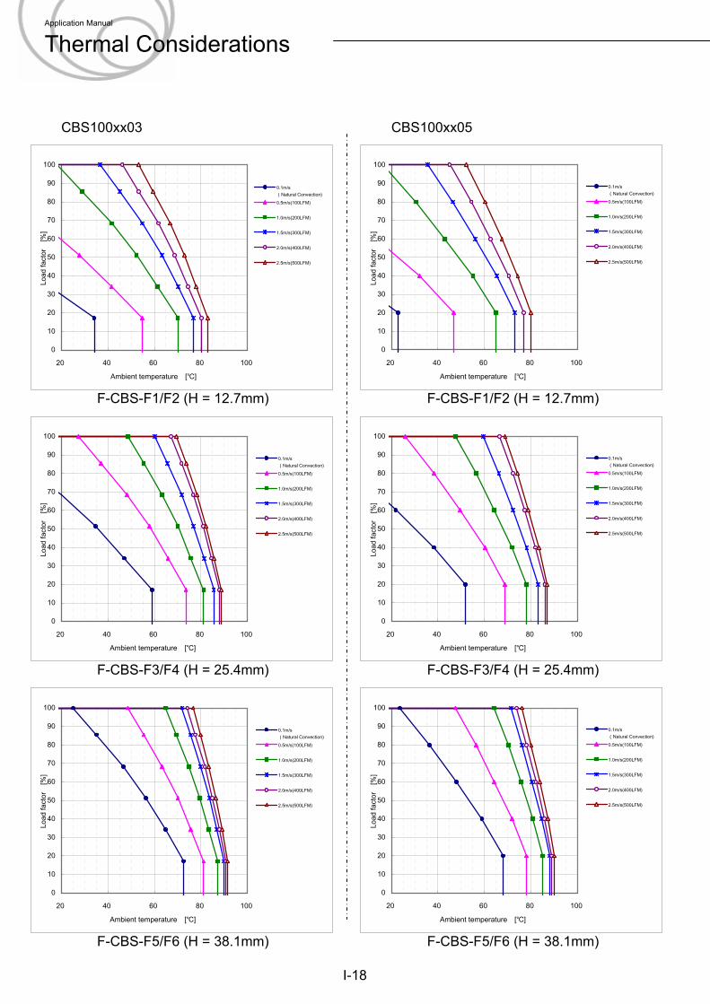
CBS100xx03 CBS100xx05
F-CBS-F1/F2 (H = 12.7mm) F-CBS-F1/F2 (H = 12.7mm)
F-CBS-F3/F4 (H = 25.4mm) F-CBS-F3/F4 (H = 25.4mm)
F-CBS-F5/F6 (H = 38.1mm) F-CBS-F5/F6 (H = 38.1mm)
I-18
0
10
20
30
40
50
60
70
80
90
100
20 40 60 80 100
Ambient temperature [℃]
Load
fact
or
[%]
0.1m/s(Natural Convection)0.5m/s(100LFM)
1.0m/s(200LFM)
1.5m/s(300LFM)
2.0m/s(400LFM)
2.5m/s(500LFM)
0
10
20
30
40
50
60
70
80
90
100
20 40 60 80 100
Ambient temperature [℃]
Load
fact
or
[%]
0.1m/s(Natural Convection)0.5m/s(100LFM)
1.0m/s(200LFM)
1.5m/s(300LFM)
2.0m/s(400LFM)
2.5m/s(500LFM)
0
10
20
30
40
50
60
70
80
90
100
20 40 60 80 100
Ambient temperature [℃]
Load
fact
or
[%]
0.1m/s(Natural Convection)0.5m/s(100LFM)
1.0m/s(200LFM)
1.5m/s(300LFM)
2.0m/s(400LFM)
2.5m/s(500LFM)
0
10
20
30
40
50
60
70
80
90
100
20 40 60 80 100
Ambient temperature [℃]Lo
ad fa
ctor
[%
]
0.1m/s(Natural Convection)0.5m/s(100LFM)
1.0m/s(200LFM)
1.5m/s(300LFM)
2.0m/s(400LFM)
2.5m/s(500LFM)
0
10
20
30
40
50
60
70
80
90
100
20 40 60 80 100
Ambient temperature [℃]
Load
fact
or
[%]
0.1m/s(Natural Convection)0.5m/s(100LFM)
1.0m/s(200LFM)
1.5m/s(300LFM)
2.0m/s(400LFM)
2.5m/s(500LFM)
0
10
20
30
40
50
60
70
80
90
100
20 40 60 80 100
Ambient temperature [℃]
Load
fact
or
[%]
0.1m/s(Natural Convection)0.5m/s(100LFM)
1.0m/s(200LFM)
1.5m/s(300LFM)
2.0m/s(400LFM)
2.5m/s(500LFM)
Application Manual
Thermal Considerations
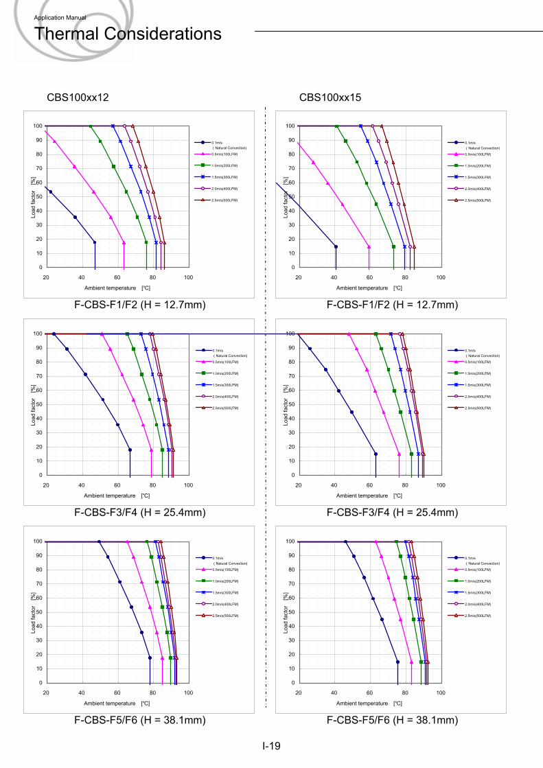
CBS100xx12 CBS100xx15
F-CBS-F1/F2 (H = 12.7mm) F-CBS-F1/F2 (H = 12.7mm)
F-CBS-F3/F4 (H = 25.4mm) F-CBS-F3/F4 (H = 25.4mm)
F-CBS-F5/F6 (H = 38.1mm) F-CBS-F5/F6 (H = 38.1mm)
I-19
0
10
20
30
40
50
60
70
80
90
100
20 40 60 80 100
Ambient temperature [℃]
Load
fact
or
[%]
0.1m/s(Natural Convection)0.5m/s(100LFM)
1.0m/s(200LFM)
1.5m/s(300LFM)
2.0m/s(400LFM)
2.5m/s(500LFM)
0
10
20
30
40
50
60
70
80
90
100
20 40 60 80 100
Ambient temperature [℃]
Load
fact
or
[%]
0.1m/s(Natural Convection)0.5m/s(100LFM)
1.0m/s(200LFM)
1.5m/s(300LFM)
2.0m/s(400LFM)
2.5m/s(500LFM)
0
10
20
30
40
50
60
70
80
90
100
20 40 60 80 100
Ambient temperature [℃]Lo
ad fa
ctor
[%
]
0.1m/s(Natural Convection)0.5m/s(100LFM)
1.0m/s(200LFM)
1.5m/s(300LFM)
2.0m/s(400LFM)
2.5m/s(500LFM)
0
10
20
30
40
50
60
70
80
90
100
20 40 60 80 100
Ambient temperature [℃]
Load
fact
or
[%]
0.1m/s(Natural Convection)0.5m/s(100LFM)
1.0m/s(200LFM)
1.5m/s(300LFM)
2.0m/s(400LFM)
2.5m/s(500LFM)
0
10
20
30
40
50
60
70
80
90
100
20 40 60 80 100
Ambient temperature [℃]
Load
fact
or
[%]
0.1m/s(Natural Convection)0.5m/s(100LFM)
1.0m/s(200LFM)
1.5m/s(300LFM)
2.0m/s(400LFM)
2.5m/s(500LFM)
0
10
20
30
40
50
60
70
80
90
100
20 40 60 80 100
Ambient temperature [℃]
Load
fact
or
[%]
0.1m/s(Natural Convection)0.5m/s(100LFM)
1.0m/s(200LFM)
1.5m/s(300LFM)
2.0m/s(400LFM)
2.5m/s(500LFM)
Application Manual
Thermal Considerations
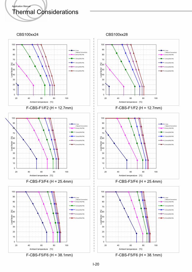
CBS100xx24 CBS100xx28
F-CBS-F1/F2 (H = 12.7mm) F-CBS-F1/F2 (H = 12.7mm)
F-CBS-F3/F4 (H = 25.4mm) F-CBS-F3/F4 (H = 25.4mm)
F-CBS-F5/F6 (H = 38.1mm) F-CBS-F5/F6 (H = 38.1mm)
I-20
0
10
20
30
40
50
60
70
80
90
100
20 40 60 80 100
Ambient temperature [℃]
Load
fact
or
[%]
0.1m/s(Natural Convection)0.5m/s(100LFM)
1.0m/s(200LFM)
1.5m/s(300LFM)
2.0m/s(400LFM)
2.5m/s(500LFM)
0
10
20
30
40
50
60
70
80
90
100
20 40 60 80 100
Ambient temperature [℃]
Load
fact
or
[%]
0.1m/s(Natural Convection)0.5m/s(100LFM)
1.0m/s(200LFM)
1.5m/s(300LFM)
2.0m/s(400LFM)
2.5m/s(500LFM)
0
10
20
30
40
50
60
70
80
90
100
20 40 60 80 100
Ambient temperature [℃]Lo
ad fa
ctor
[%
]
0.1m/s(Natural Convection)0.5m/s(100LFM)
1.0m/s(200LFM)
1.5m/s(300LFM)
2.0m/s(400LFM)
2.5m/s(500LFM)
0
10
20
30
40
50
60
70
80
90
100
20 40 60 80 100
Ambient temperature [℃]
Load
fact
or
[%]
0.1m/s(Natural Convection)0.5m/s(100LFM)
1.0m/s(200LFM)
1.5m/s(300LFM)
2.0m/s(400LFM)
2.5m/s(500LFM)
0
10
20
30
40
50
60
70
80
90
100
20 40 60 80 100
Ambient temperature [℃]
Load
fact
or
[%]
0.1m/s(Natural Convection)0.5m/s(100LFM)
1.0m/s(200LFM)
1.5m/s(300LFM)
2.0m/s(400LFM)
2.5m/s(500LFM)
0
10
20
30
40
50
60
70
80
90
100
20 40 60 80 100
Ambient temperature [℃]
Load
fact
or
[%]
0.1m/s(Natural Convection)0.5m/s(100LFM)
1.0m/s(200LFM)
1.5m/s(300LFM)
2.0m/s(400LFM)
2.5m/s(500LFM)
Application Manual
Thermal Considerations
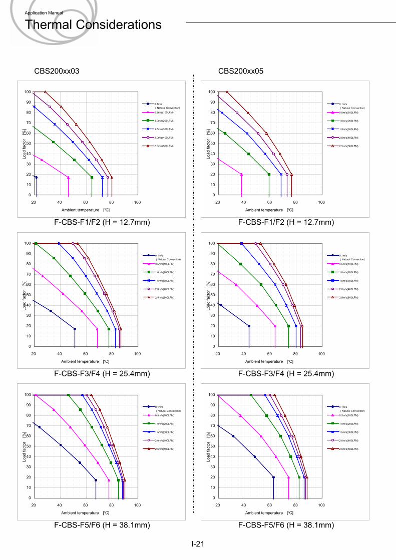
CBS200xx03 CBS200xx05
F-CBS-F1/F2 (H = 12.7mm) F-CBS-F1/F2 (H = 12.7mm)
F-CBS-F3/F4 (H = 25.4mm) F-CBS-F3/F4 (H = 25.4mm)
F-CBS-F5/F6 (H = 38.1mm) F-CBS-F5/F6 (H = 38.1mm)
I-21
0
10
20
30
40
50
60
70
80
90
100
20 40 60 80 100
Ambient temperature [℃]
Load
fact
or
[%]
0.1m/s(Natural Convection)0.5m/s(100LFM)
1.0m/s(200LFM)
1.5m/s(300LFM)
2.0m/s(400LFM)
2.5m/s(500LFM)
0
10
20
30
40
50
60
70
80
90
100
20 40 60 80 100
Ambient temperature [℃]
Load
fact
or
[%]
0.1m/s(Natural Convection)0.5m/s(100LFM)
1.0m/s(200LFM)
1.5m/s(300LFM)
2.0m/s(400LFM)
2.5m/s(500LFM)
0
10
20
30
40
50
60
70
80
90
100
20 40 60 80 100
Ambient temperature [℃]Lo
ad fa
ctor
[%
]
0.1m/s(Natural Convection)0.5m/s(100LFM)
1.0m/s(200LFM)
1.5m/s(300LFM)
2.0m/s(400LFM)
2.5m/s(500LFM)
0
10
20
30
40
50
60
70
80
90
100
20 40 60 80 100
Ambient temperature [℃]
Load
fact
or
[%]
0.1m/s(Natural Convection)0.5m/s(100LFM)
1.0m/s(200LFM)
1.5m/s(300LFM)
2.0m/s(400LFM)
2.5m/s(500LFM)
0
10
20
30
40
50
60
70
80
90
100
20 40 60 80 100
Ambient temperature [℃]
Load
fact
or
[%]
0.1m/s(Natural Convection)0.5m/s(100LFM)
1.0m/s(200LFM)
1.5m/s(300LFM)
2.0m/s(400LFM)
2.5m/s(500LFM)
0
10
20
30
40
50
60
70
80
90
100
20 40 60 80 100
Ambient temperature [℃]
Load
fact
or
[%]
0.1m/s(Natural Convection)0.5m/s(100LFM)
1.0m/s(200LFM)
1.5m/s(300LFM)
2.0m/s(400LFM)
2.5m/s(500LFM)
Application Manual
Thermal Considerations
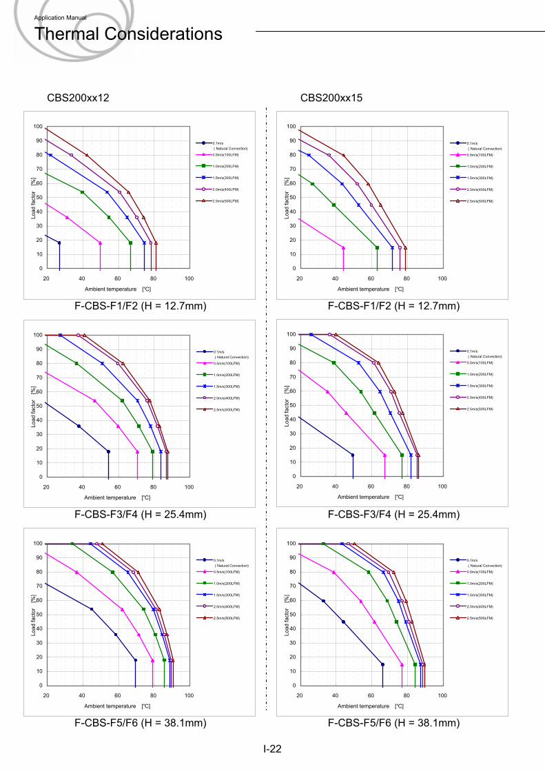
CBS200xx12 CBS200xx15
F-CBS-F1/F2 (H = 12.7mm) F-CBS-F1/F2 (H = 12.7mm)
F-CBS-F3/F4 (H = 25.4mm) F-CBS-F3/F4 (H = 25.4mm)
F-CBS-F5/F6 (H = 38.1mm) F-CBS-F5/F6 (H = 38.1mm)
I-22
0
10
20
30
40
50
60
70
80
90
100
20 40 60 80 100
Ambient temperature [℃]
Load
fact
or
[%]
0.1m/s(Natural Convection)0.5m/s(100LFM)
1.0m/s(200LFM)
1.5m/s(300LFM)
2.0m/s(400LFM)
2.5m/s(500LFM)
0
10
20
30
40
50
60
70
80
90
100
20 40 60 80 100
Ambient temperature [℃]
Load
fact
or
[%]
0.1m/s(Natural Convection)0.5m/s(100LFM)
1.0m/s(200LFM)
1.5m/s(300LFM)
2.0m/s(400LFM)
2.5m/s(500LFM)
0
10
20
30
40
50
60
70
80
90
100
20 40 60 80 100
Ambient temperature [℃]Lo
ad fa
ctor
[%
]
0.1m/s(Natural Convection)0.5m/s(100LFM)
1.0m/s(200LFM)
1.5m/s(300LFM)
2.0m/s(400LFM)
2.5m/s(500LFM)
0
10
20
30
40
50
60
70
80
90
100
20 40 60 80 100
Ambient temperature [℃]
Load
fact
or
[%]
0.1m/s(Natural Convection)0.5m/s(100LFM)
1.0m/s(200LFM)
1.5m/s(300LFM)
2.0m/s(400LFM)
2.5m/s(500LFM)
0
10
20
30
40
50
60
70
80
90
100
20 40 60 80 100
Ambient temperature [℃]
Load
fact
or
[%]
0.1m/s(Natural Convection)0.5m/s(100LFM)
1.0m/s(200LFM)
1.5m/s(300LFM)
2.0m/s(400LFM)
2.5m/s(500LFM)
0
10
20
30
40
50
60
70
80
90
100
20 40 60 80 100
Ambient temperature [℃]
Load
fact
or
[%]
0.1m/s(Natural Convection)0.5m/s(100LFM)
1.0m/s(200LFM)
1.5m/s(300LFM)
2.0m/s(400LFM)
2.5m/s(500LFM)
Application Manual
Thermal Considerations
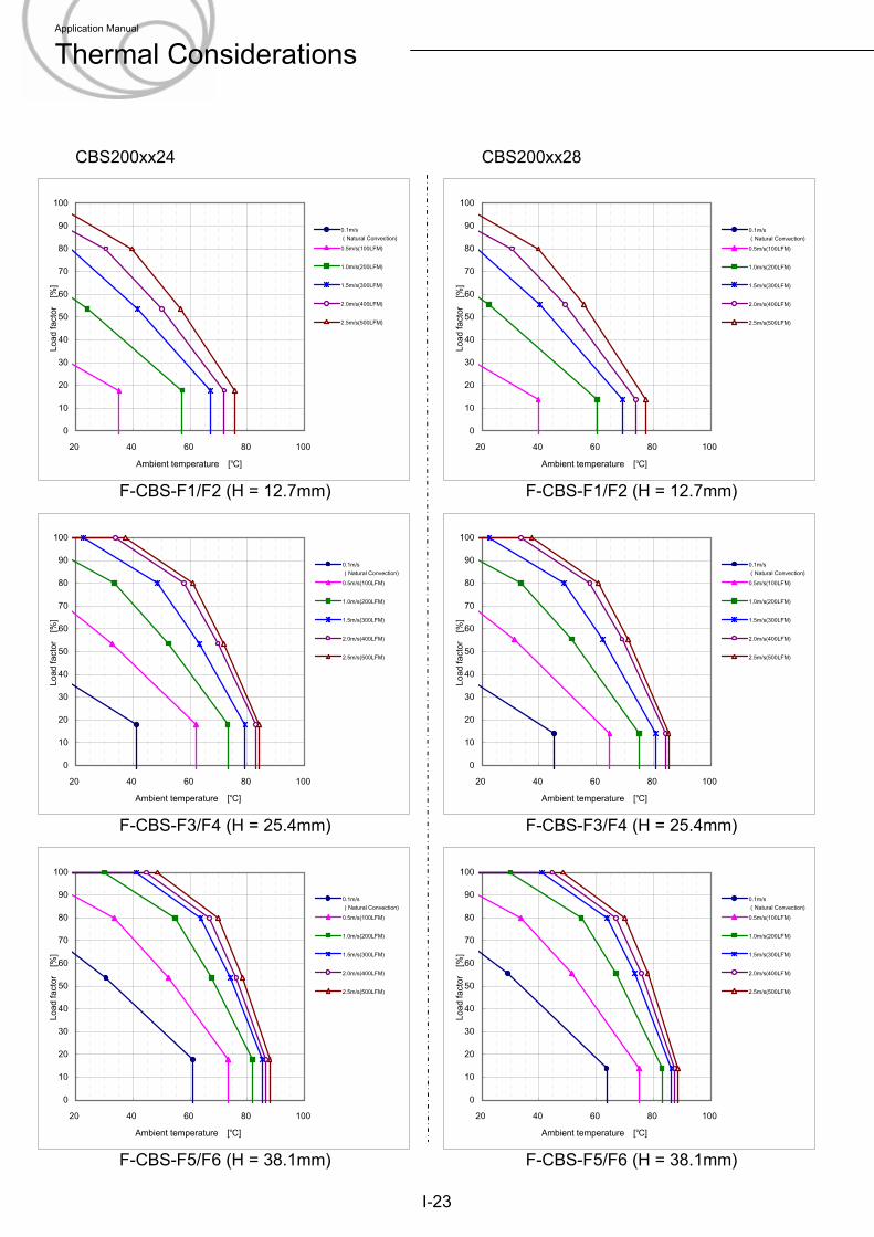
CBS200xx24 CBS200xx28
F-CBS-F1/F2 (H = 12.7mm) F-CBS-F1/F2 (H = 12.7mm)
F-CBS-F3/F4 (H = 25.4mm) F-CBS-F3/F4 (H = 25.4mm)
F-CBS-F5/F6 (H = 38.1mm) F-CBS-F5/F6 (H = 38.1mm)
I-23
0
10
20
30
40
50
60
70
80
90
100
20 40 60 80 100
Ambient temperature [℃]
Load
fact
or
[%]
0.1m/s(Natural Convection)0.5m/s(100LFM)
1.0m/s(200LFM)
1.5m/s(300LFM)
2.0m/s(400LFM)
2.5m/s(500LFM)
0
10
20
30
40
50
60
70
80
90
100
20 40 60 80 100
Ambient temperature [℃]
Load
fact
or
[%]
0.1m/s(Natural Convection)0.5m/s(100LFM)
1.0m/s(200LFM)
1.5m/s(300LFM)
2.0m/s(400LFM)
2.5m/s(500LFM)
0
10
20
30
40
50
60
70
80
90
100
20 40 60 80 100
Ambient temperature [℃]Lo
ad fa
ctor
[%
]
0.1m/s(Natural Convection)0.5m/s(100LFM)
1.0m/s(200LFM)
1.5m/s(300LFM)
2.0m/s(400LFM)
2.5m/s(500LFM)
0
10
20
30
40
50
60
70
80
90
100
20 40 60 80 100
Ambient temperature [℃]
Load
fact
or
[%]
0.1m/s(Natural Convection)0.5m/s(100LFM)
1.0m/s(200LFM)
1.5m/s(300LFM)
2.0m/s(400LFM)
2.5m/s(500LFM)
0
10
20
30
40
50
60
70
80
90
100
20 40 60 80 100
Ambient temperature [℃]
Load
fact
or
[%]
0.1m/s(Natural Convection)0.5m/s(100LFM)
1.0m/s(200LFM)
1.5m/s(300LFM)
2.0m/s(400LFM)
2.5m/s(500LFM)
0
10
20
30
40
50
60
70
80
90
100
20 40 60 80 100
Ambient temperature [℃]
Load
fact
or
[%]
0.1m/s(Natural Convection)0.5m/s(100LFM)
1.0m/s(200LFM)
1.5m/s(300LFM)
2.0m/s(400LFM)
2.5m/s(500LFM)
Application Manual
Thermal Considerations
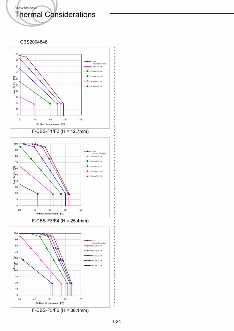
CBS2004848
F-CBS-F1/F2 (H = 12.7mm)
F-CBS-F3/F4 (H = 25.4mm)
F-CBS-F5/F6 (H = 38.1mm)
I-24
0
10
20
30
40
50
60
70
80
90
100
20 40 60 80 100
Ambient temperature [℃]
Load
fact
or
[%]
0.1m/s(Natural Convection)0.5m/s(100LFM)
1.0m/s(200LFM)
1.5m/s(300LFM)
2.0m/s(400LFM)
2.5m/s(500LFM)
0
10
20
30
40
50
60
70
80
90
100
20 40 60 80 100Ambient temperature [℃]
Load
fact
or
[%]
0.1m/s(Natural Convection)0.5m/s(100LFM)
1.0m/s(200LFM)
1.5m/s(300LFM)
2.0m/s(400LFM)
2.5m/s(500LFM)
0
10
20
30
40
50
60
70
80
90
100
20 40 60 80 100Ambient temperature [℃]
Load
fact
or
[%]
0.1m/s(Natural Convection)0.5m/s(100LFM)
1.0m/s(200LFM)
1.5m/s(300LFM)
2.0m/s(400LFM)
2.5m/s(500LFM)
Application Manual
Thermal Considerations
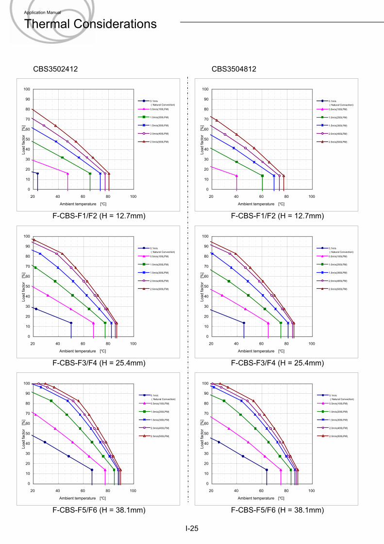
CBS3502412 CBS3504812
F-CBS-F1/F2 (H = 12.7mm) F-CBS-F1/F2 (H = 12.7mm)
I-25
F-CBS-F3/F4 (H = 25.4mm) F-CBS-F3/F4 (H = 25.4mm)
F-CBS-F5/F6 (H = 38.1mm) F-CBS-F5/F6 (H = 38.1mm)
0
10
20
30
40
50
60
70
80
90
100
20 40 60 80 100
Ambient temperature [℃]
Load
fact
or
[%]
0.1m/s(Natural Convection)0.5m/s(100LFM)
1.0m/s(200LFM)
1.5m/s(300LFM)
2.0m/s(400LFM)
2.5m/s(500LFM)
0
10
20
30
40
50
60
70
80
90
100
20 40 60 80 100
Ambient temperature [℃]
Load
fact
or
[%]
0.1m/s(Natural Convection)0.5m/s(100LFM)
1.0m/s(200LFM)
1.5m/s(300LFM)
2.0m/s(400LFM)
2.5m/s(500LFM)
0
10
20
30
40
50
60
70
80
90
100
20 40 60 80 100
Ambient temperature [℃]Lo
ad fa
ctor
[%
]
0.1m/s(Natural Convection)0.5m/s(100LFM)
1.0m/s(200LFM)
1.5m/s(300LFM)
2.0m/s(400LFM)
2.5m/s(500LFM)
0
10
20
30
40
50
60
70
80
90
100
20 40 60 80 100
Ambient temperature [℃]
Load
fact
or
[%]
0.1m/s(Natural Convection)0.5m/s(100LFM)
1.0m/s(200LFM)
1.5m/s(300LFM)
2.0m/s(400LFM)
2.5m/s(500LFM)
0
10
20
30
40
50
60
70
80
90
100
20 40 60 80 100
Ambient temperature [℃]
Load
fact
or
[%]
0.1m/s(Natural Convection)0.5m/s(100LFM)
1.0m/s(200LFM)
1.5m/s(300LFM)
2.0m/s(400LFM)
2.5m/s(500LFM)
0
10
20
30
40
50
60
70
80
90
100
20 40 60 80 100
Ambient temperature [℃]
Load
fact
or
[%]
0.1m/s(Natural Convection)0.5m/s(100LFM)
1.0m/s(200LFM)
1.5m/s(300LFM)
2.0m/s(400LFM)
2.5m/s(500LFM)
Application Manual
Thermal Considerations
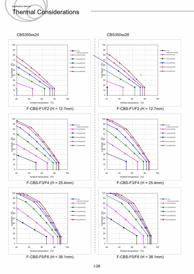
CBS350xx24 CBS350xx28
F-CBS-F1/F2 (H = 12.7mm) F-CBS-F1/F2 (H = 12.7mm)
F-CBS-F3/F4 (H = 25.4mm) F-CBS-F3/F4 (H = 25.4mm)
F-CBS-F5/F6 (H = 38.1mm) F-CBS-F5/F6 (H = 38.1mm)
I-26
0
10
20
30
40
50
60
70
80
90
100
20 40 60 80 100
Ambient temperature [℃]
Load
fact
or
[%]
0.1m/s(Natural Convection)0.5m/s(100LFM)
1.0m/s(200LFM)
1.5m/s(300LFM)
2.0m/s(400LFM)
2.5m/s(500LFM)
0
10
20
30
40
50
60
70
80
90
100
20 40 60 80 100
Ambient temperature [℃]
Load
fact
or
[%]
0.1m/s(Natural Convection)0.5m/s(100LFM)
1.0m/s(200LFM)
1.5m/s(300LFM)
2.0m/s(400LFM)
2.5m/s(500LFM)
0
10
20
30
40
50
60
70
80
90
100
20 40 60 80 100
Ambient temperature [℃]
Load
fact
or
[%]
0.1m/s(Natural Convection)0.5m/s(100LFM)
1.0m/s(200LFM)
1.5m/s(300LFM)
2.0m/s(400LFM)
2.5m/s(500LFM)
0
10
20
30
40
50
60
70
80
90
100
20 40 60 80 100
Ambient temperature [℃]Lo
ad fa
ctor
[%
]
0.1m/s(Natural Convection)0.5m/s(100LFM)
1.0m/s(200LFM)
1.5m/s(300LFM)
2.0m/s(400LFM)
2.5m/s(500LFM)
y
0
10
20
30
40
50
60
70
80
90
100
20 40 60 80 100
Ambient temperature [℃]
Load
fact
or
[%]
0.1m/s(Natural Convection)0.5m/s(100LFM)
1.0m/s(200LFM)
1.5m/s(300LFM)
2.0m/s(400LFM)
2.5m/s(500LFM)
0
10
20
30
40
50
60
70
80
90
100
20 40 60 80 100
Ambient temperature [℃]
Load
fact
or
[%]
0.1m/s(Natural Convection)0.5m/s(100LFM)
1.0m/s(200LFM)
1.5m/s(300LFM)
2.0m/s(400LFM)
2.5m/s(500LFM)
Application Manual
Thermal Considerations
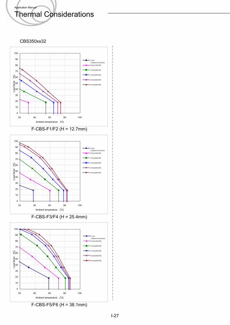
CBS350xx32
F-CBS-F1/F2 (H = 12.7mm)
I-27
F-CBS-F3/F4 (H = 25.4mm)
F-CBS-F5/F6 (H = 38.1mm)
0
10
20
30
40
50
60
70
80
90
100
20 40 60 80 100
Ambient temperature [℃]
Load
fact
or
[%]
0.1m/s(Natural Convection)0.5m/s(100LFM)
1.0m/s(200LFM)
1.5m/s(300LFM)
2.0m/s(400LFM)
2.5m/s(500LFM)
0
10
20
30
40
50
60
70
80
90
100
20 40 60 80 100
Ambient temperature [℃]
Load
fact
or
[%]
0.1m/s(Natural Convection)0.5m/s(100LFM)
1.0m/s(200LFM)
1.5m/s(300LFM)
2.0m/s(400LFM)
2.5m/s(500LFM)
0
10
20
30
40
50
60
70
80
90
100
20 40 60 80 100
Ambient temperature [℃]
Load
fact
or
[%]
0.1m/s(Natural Convection)0.5m/s(100LFM)
1.0m/s(200LFM)
1.5m/s(300LFM)
2.0m/s(400LFM)
2.5m/s(500LFM)
Application Manual
Thermal Considerations
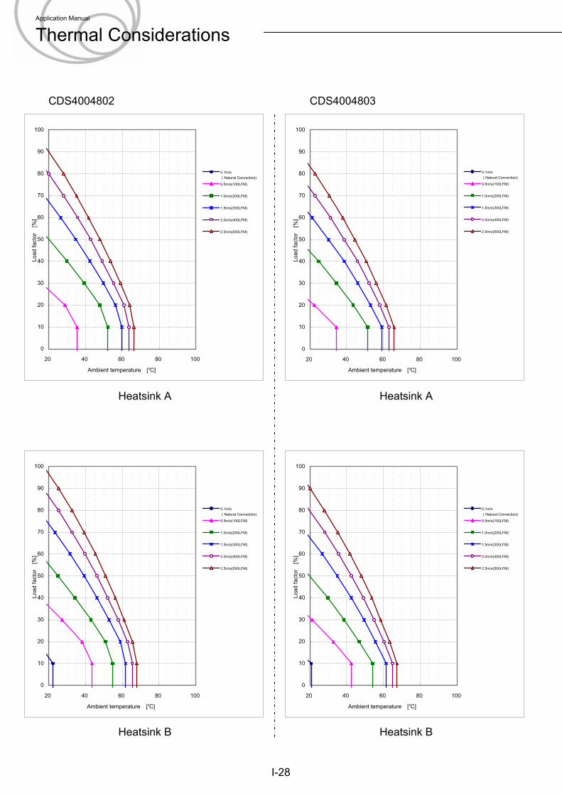
CDS4004802 CDS4004803
I-28
Heatsink A Heatsink A
Heatsink B Heatsink B
0
10
20
30
40
50
60
70
80
90
100
20 40 60 80 100
Ambient temperature [℃]
Load
fact
or
[%]
0.1m/s(Natural Convection)0.5m/s(100LFM)
1.0m/s(200LFM)
1.5m/s(300LFM)
2.0m/s(400LFM)
2.5m/s(500LFM)
0
10
20
30
40
50
60
70
80
90
100
20 40 60 80 100
Ambient temperature [℃]
Load
fact
or
[%]
0.1m/s(Natural Convection)0.5m/s(100LFM)
1.0m/s(200LFM)
1.5m/s(300LFM)
2.0m/s(400LFM)
2.5m/s(500LFM)
0
10
20
30
40
50
60
70
80
90
100
20 40 60 80 100
Ambient temperature [℃]
Load
fact
or
[%]
0.1m/s(Natural Convection)0.5m/s(100LFM)
1.0m/s(200LFM)
1.5m/s(300LFM)
2.0m/s(400LFM)
2.5m/s(500LFM)
0
10
20
30
40
50
60
70
80
90
100
20 40 60 80 100
Ambient temperature [℃]
Load
fact
or
[%]
0.1m/s(Natural Convection)0.5m/s(100LFM)
1.0m/s(200LFM)
1.5m/s(300LFM)
2.0m/s(400LFM)
2.5m/s(500LFM)
Application Manual
Thermal Considerations
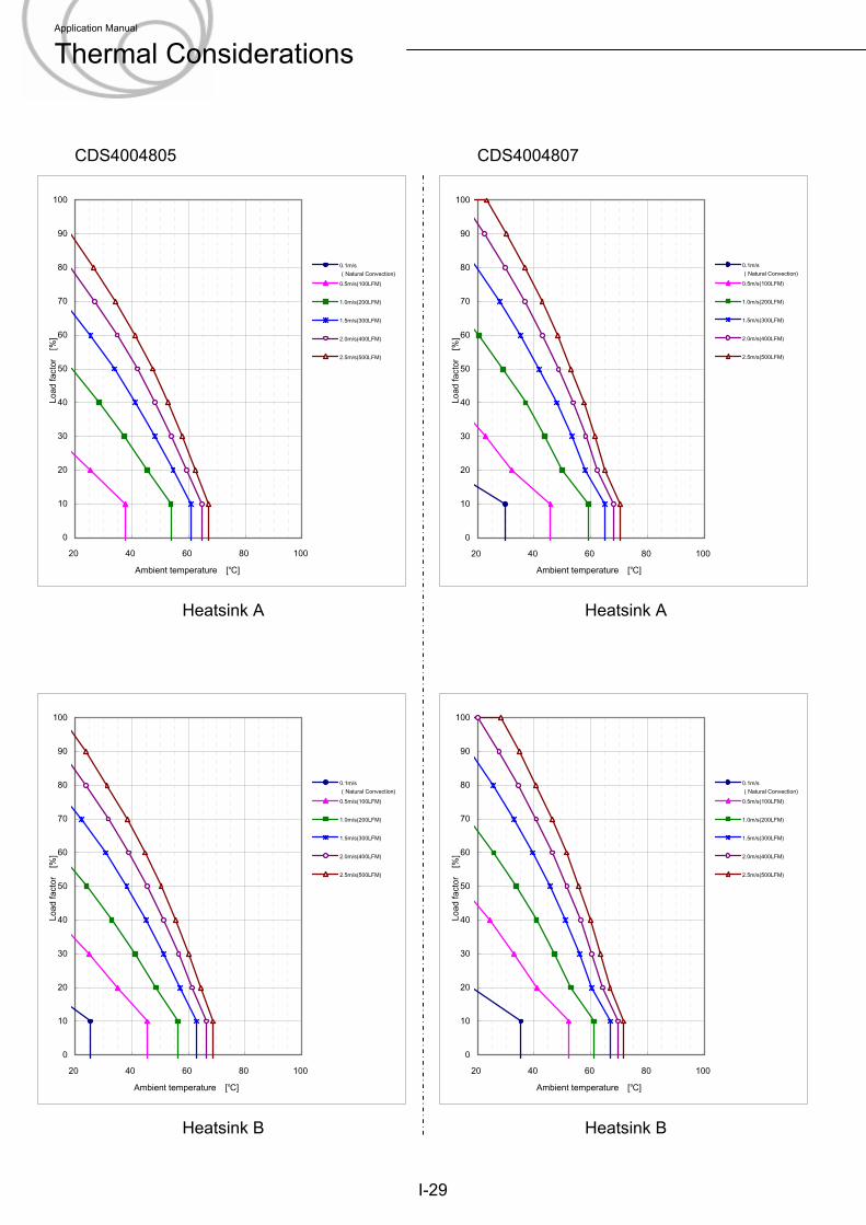
CDS4004805 CDS4004807
I-29
Heatsink A Heatsink A
Heatsink B Heatsink B
0
10
20
30
40
50
60
70
80
90
100
20 40 60 80 100
Ambient temperature [℃]
Load
fact
or
[%]
0.1m/s(Natural Convection)0.5m/s(100LFM)
1.0m/s(200LFM)
1.5m/s(300LFM)
2.0m/s(400LFM)
2.5m/s(500LFM)
0
10
20
30
40
50
60
70
80
90
100
20 40 60 80 100
Ambient temperature [℃]
Load
fact
or
[%]
0.1m/s(Natural Convection)0.5m/s(100LFM)
1.0m/s(200LFM)
1.5m/s(300LFM)
2.0m/s(400LFM)
2.5m/s(500LFM)
0
10
20
30
40
50
60
70
80
90
100
20 40 60 80 100
Ambient temperature [℃]
Load
fact
or
[%]
0.1m/s(Natural Convection)0.5m/s(100LFM)
1.0m/s(200LFM)
1.5m/s(300LFM)
2.0m/s(400LFM)
2.5m/s(500LFM)
0
10
20
30
40
50
60
70
80
90
100
20 40 60 80 100
Ambient temperature [℃]
Load
fact
or
[%]
0.1m/s(Natural Convection)0.5m/s(100LFM)
1.0m/s(200LFM)
1.5m/s(300LFM)
2.0m/s(400LFM)
2.5m/s(500LFM)
Application Manual
Thermal Considerations
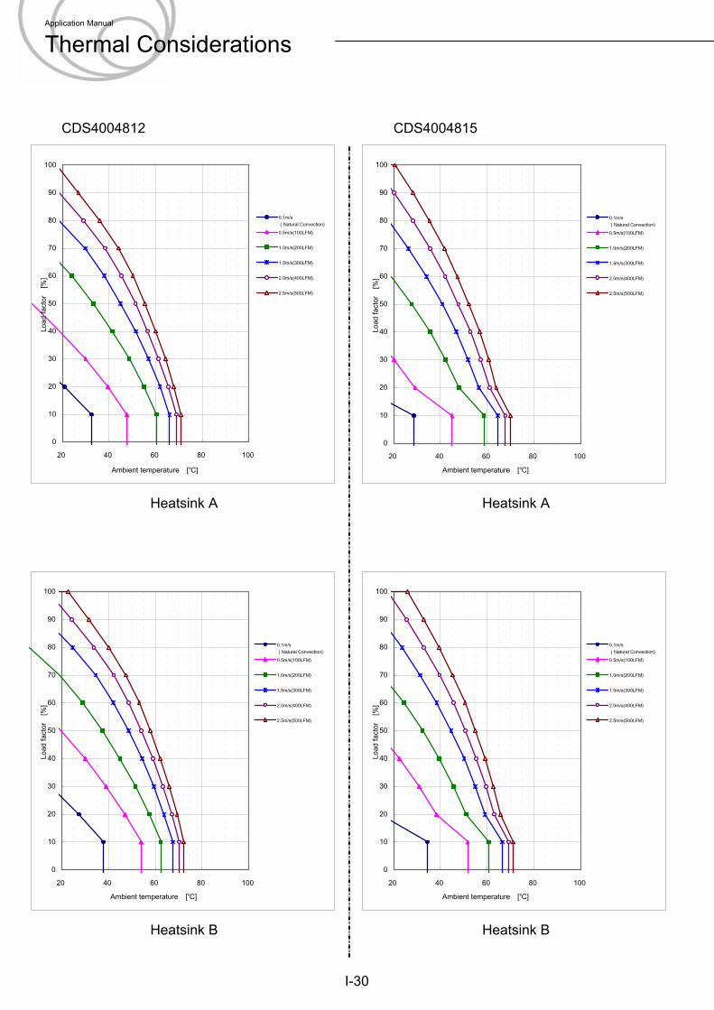
CDS4004812 CDS4004815
I-30
Heatsink A Heatsink A
Heatsink B Heatsink B
0
10
20
30
40
50
60
70
80
90
100
20 40 60 80 100
Ambient temperature [℃]
Load
fact
or
[%]
0.1m/s(Natural Convection)0.5m/s(100LFM)
1.0m/s(200LFM)
1.5m/s(300LFM)
2.0m/s(400LFM)
2.5m/s(500LFM)
0
10
20
30
40
50
60
70
80
90
100
20 40 60 80 100
Ambient temperature [℃]
Load
fact
or
[%]
0.1m/s(Natural Convection)0.5m/s(100LFM)
1.0m/s(200LFM)
1.5m/s(300LFM)
2.0m/s(400LFM)
2.5m/s(500LFM)
0
10
20
30
40
50
60
70
80
90
100
20 40 60 80 100
Ambient temperature [℃]
Load
fact
or
[%]
0.1m/s(Natural Convection)0.5m/s(100LFM)
1.0m/s(200LFM)
1.5m/s(300LFM)
2.0m/s(400LFM)
2.5m/s(500LFM)
0
10
20
30
40
50
60
70
80
90
100
20 40 60 80 100
Ambient temperature [℃]
Load
fact
or
[%]
0.1m/s(Natural Convection)0.5m/s(100LFM)
1.0m/s(200LFM)
1.5m/s(300LFM)
2.0m/s(400LFM)
2.5m/s(500LFM)
Application Manual
Thermal Considerations
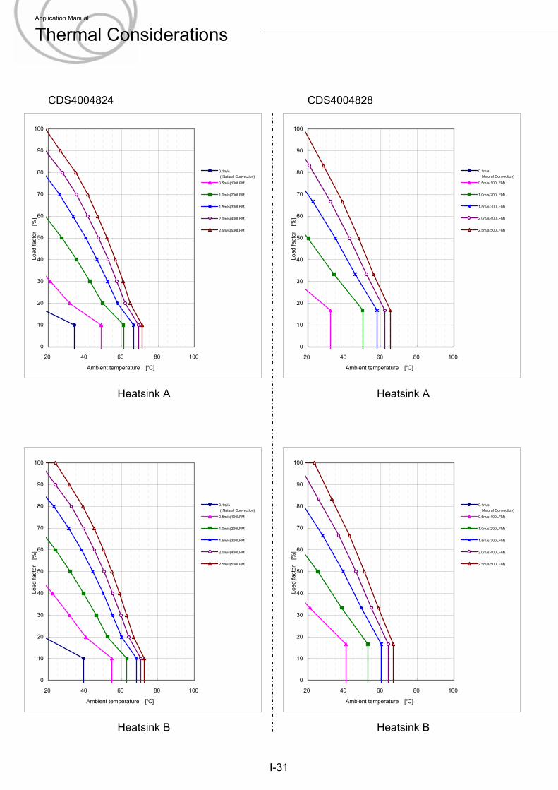
CDS4004824 CDS4004828
I-31
Heatsink A Heatsink A
Heatsink B Heatsink B
0
10
20
30
40
50
60
70
80
90
100
20 40 60 80 100
Ambient temperature [℃]
Load
fact
or
[%]
0.1m/s(Natural Convection)0.5m/s(100LFM)
1.0m/s(200LFM)
1.5m/s(300LFM)
2.0m/s(400LFM)
2.5m/s(500LFM)
0
10
20
30
40
50
60
70
80
90
100
20 40 60 80 100
Ambient temperature [℃]
Load
fact
or
[%]
0.1m/s(Natural Convection)0.5m/s(100LFM)
1.0m/s(200LFM)
1.5m/s(300LFM)
2.0m/s(400LFM)
2.5m/s(500LFM)
0
10
20
30
40
50
60
70
80
90
100
20 40 60 80 100
Ambient temperature [℃]
Load
fact
or
[%]
0.1m/s(Natural Convection)0.5m/s(100LFM)
1.0m/s(200LFM)
1.5m/s(300LFM)
2.0m/s(400LFM)
2.5m/s(500LFM)
0
10
20
30
40
50
60
70
80
90
100
20 40 60 80 100
Ambient temperature [℃]
Load
fact
or
[%]
0.1m/s(Natural Convection)0.5m/s(100LFM)
1.0m/s(200LFM)
1.5m/s(300LFM)
2.0m/s(400LFM)
2.5m/s(500LFM)
Application Manual
Thermal Considerations
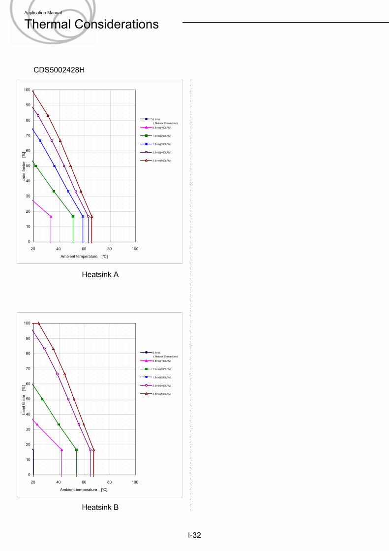
CDS5002428H
I-32
Heatsink A
Heatsink B
0
10
20
30
40
50
60
70
80
90
100
20 40 60 80 100
Ambient temperature [℃]
Load
fact
or
[%]
0.1m/s(Natural Convection)0.5m/s(100LFM)
1.0m/s(200LFM)
1.5m/s(300LFM)
2.0m/s(400LFM)
2.5m/s(500LFM)
0
10
20
30
40
50
60
70
80
90
100
20 40 60 80 100
Ambient temperature [℃]
Load
fact
or
[%]
0.1m/s(Natural Convection)0.5m/s(100LFM)
1.0m/s(200LFM)
1.5m/s(300LFM)
2.0m/s(400LFM)
2.5m/s(500LFM)
Application Manual
Thermal Considerations
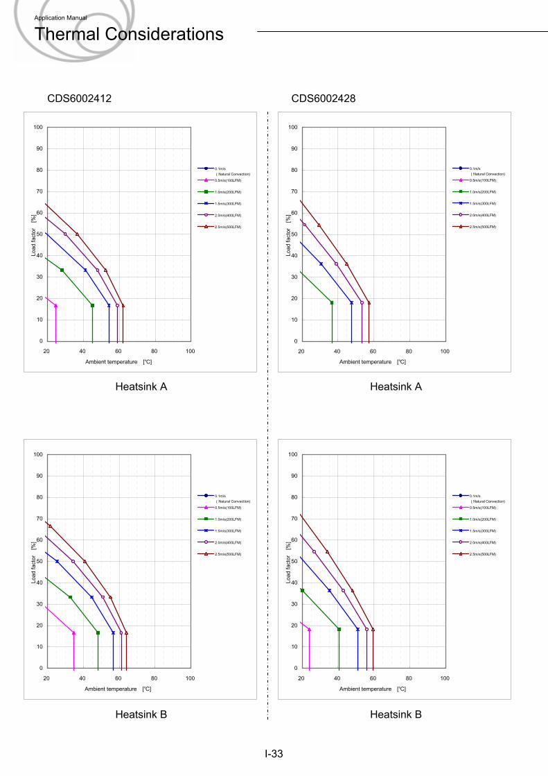
CDS6002412 CDS6002428
I-33
Heatsink A Heatsink A
Heatsink B Heatsink B
0
10
20
30
40
50
60
70
80
90
100
20 40 60 80 100
Ambient temperature [℃]
Load
fact
or
[%]
0.1m/s(Natural Convection)0.5m/s(100LFM)
1.0m/s(200LFM)
1.5m/s(300LFM)
2.0m/s(400LFM)
2.5m/s(500LFM)
0
10
20
30
40
50
60
70
80
90
100
20 40 60 80 100
Ambient temperature [℃]
Load
fact
or
[%]
0.1m/s(Natural Convection)0.5m/s(100LFM)
1.0m/s(200LFM)
1.5m/s(300LFM)
2.0m/s(400LFM)
2.5m/s(500LFM)
0
10
20
30
40
50
60
70
80
90
100
20 40 60 80 100
Ambient temperature [℃]
Load
fact
or
[%]
0.1m/s(Natural Convection)0.5m/s(100LFM)
1.0m/s(200LFM)
1.5m/s(300LFM)
2.0m/s(400LFM)
2.5m/s(500LFM)
0
10
20
30
40
50
60
70
80
90
100
20 40 60 80 100
Ambient temperature [℃]
Load
fact
or
[%]
0.1m/s(Natural Convection)0.5m/s(100LFM)
1.0m/s(200LFM)
1.5m/s(300LFM)
2.0m/s(400LFM)
2.5m/s(500LFM)
Application Manual
Thermal Considerations
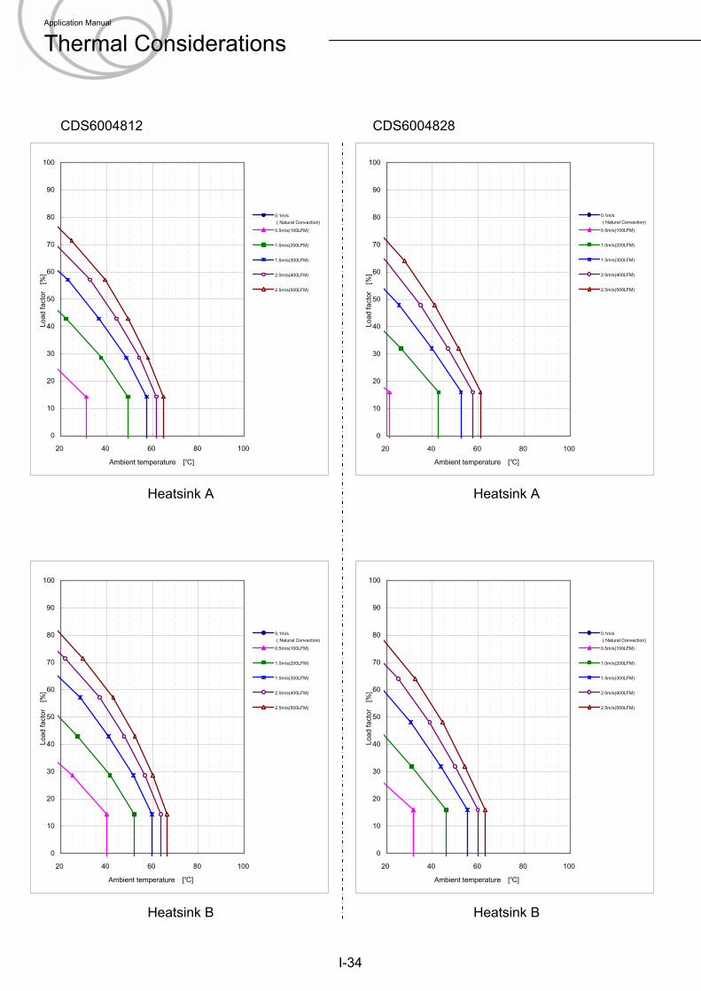
CDS6004812 CDS6004828
I-34
Heatsink A Heatsink A
Heatsink B Heatsink B
0
10
20
30
40
50
60
70
80
90
100
20 40 60 80 100
Ambient temperature [℃]
Load
fact
or
[%]
0.1m/s(Natural Convection)0.5m/s(100LFM)
1.0m/s(200LFM)
1.5m/s(300LFM)
2.0m/s(400LFM)
2.5m/s(500LFM)
0
10
20
30
40
50
60
70
80
90
100
20 40 60 80 100
Ambient temperature [℃]
Load
fact
or
[%]
0.1m/s(Natural Convection)0.5m/s(100LFM)
1.0m/s(200LFM)
1.5m/s(300LFM)
2.0m/s(400LFM)
2.5m/s(500LFM)
0
10
20
30
40
50
60
70
80
90
100
20 40 60 80 100
Ambient temperature [℃]
Load
fact
or
[%]
0.1m/s(Natural Convection)0.5m/s(100LFM)
1.0m/s(200LFM)
1.5m/s(300LFM)
2.0m/s(400LFM)
2.5m/s(500LFM)
0
10
20
30
40
50
60
70
80
90
100
20 40 60 80 100
Ambient temperature [℃]
Load
fact
or
[%]
0.1m/s(Natural Convection)0.5m/s(100LFM)
1.0m/s(200LFM)
1.5m/s(300LFM)
2.0m/s(400LFM)
2.5m/s(500LFM)
Application Manual
Thermal Considerations
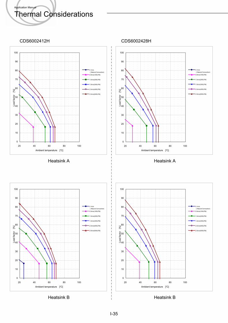
CDS6002412H CDS6002428H
I-35
Heatsink A Heatsink A
Heatsink B Heatsink B
0
10
20
30
40
50
60
70
80
90
100
20 40 60 80 100
Ambient temperature [℃]
Load
fact
or
[%]
0.1m/s(Natural Convection)0.5m/s(100LFM)
1.0m/s(200LFM)
1.5m/s(300LFM)
2.0m/s(400LFM)
2.5m/s(500LFM)
0
10
20
30
40
50
60
70
80
90
100
20 40 60 80 100
Ambient temperature [℃]
Load
fact
or
[%]
0.1m/s(Natural Convection)0.5m/s(100LFM)
1.0m/s(200LFM)
1.5m/s(300LFM)
2.0m/s(400LFM)
2.5m/s(500LFM)
0
10
20
30
40
50
60
70
80
90
100
20 40 60 80 100
Ambient temperature [℃]
Load
fact
or
[%]
0.1m/s(Natural Convection)0.5m/s(100LFM)
1.0m/s(200LFM)
1.5m/s(300LFM)
2.0m/s(400LFM)
2.5m/s(500LFM)
0
10
20
30
40
50
60
70
80
90
100
20 40 60 80 100
Ambient temperature [℃]
Load
fact
or
[%]
0.1m/s(Natural Convection)0.5m/s(100LFM)
1.0m/s(200LFM)
1.5m/s(300LFM)
2.0m/s(400LFM)
2.5m/s(500LFM)
Application Manual
Thermal Considerations
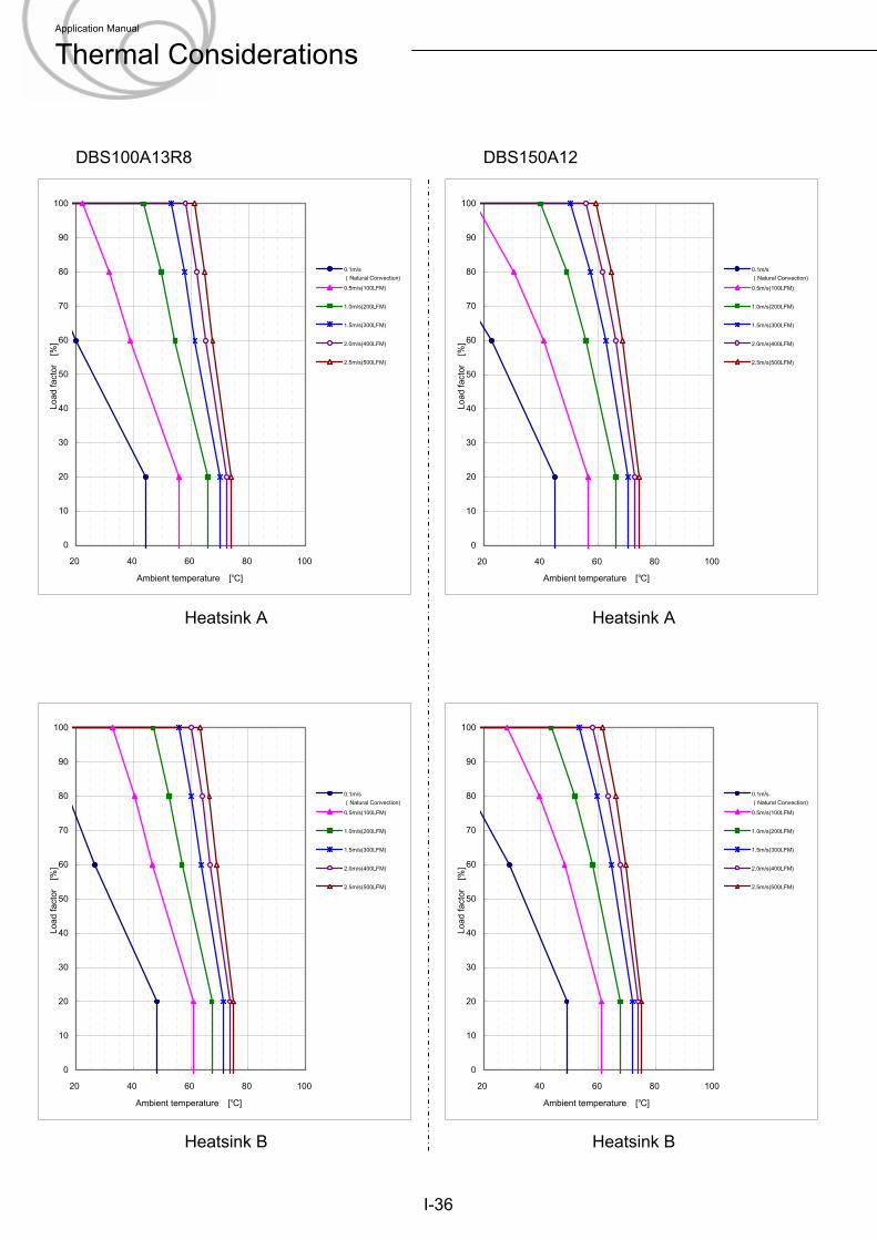
DBS100A13R8 DBS150A12
I-36
Heatsink A Heatsink A
Heatsink B Heatsink B
0
10
20
30
40
50
60
70
80
90
100
20 40 60 80 100
Ambient temperature [℃]
Load
fact
or
[%]
0.1m/s(Natural Convection)0.5m/s(100LFM)
1.0m/s(200LFM)
1.5m/s(300LFM)
2.0m/s(400LFM)
2.5m/s(500LFM)
0
10
20
30
40
50
60
70
80
90
100
20 40 60 80 100
Ambient temperature [℃]
Load
fact
or
[%]
0.1m/s(Natural Convection)0.5m/s(100LFM)
1.0m/s(200LFM)
1.5m/s(300LFM)
2.0m/s(400LFM)
2.5m/s(500LFM)
0
10
20
30
40
50
60
70
80
90
100
20 40 60 80 100
Ambient temperature [℃]
Load
fact
or
[%]
0.1m/s(Natural Convection)0.5m/s(100LFM)
1.0m/s(200LFM)
1.5m/s(300LFM)
2.0m/s(400LFM)
2.5m/s(500LFM)
0
10
20
30
40
50
60
70
80
90
100
20 40 60 80 100
Ambient temperature [℃]
Load
fact
or
[%]
0.1m/s(Natural Convection)0.5m/s(100LFM)
1.0m/s(200LFM)
1.5m/s(300LFM)
2.0m/s(400LFM)
2.5m/s(500LFM)
Application Manual
Thermal Considerations
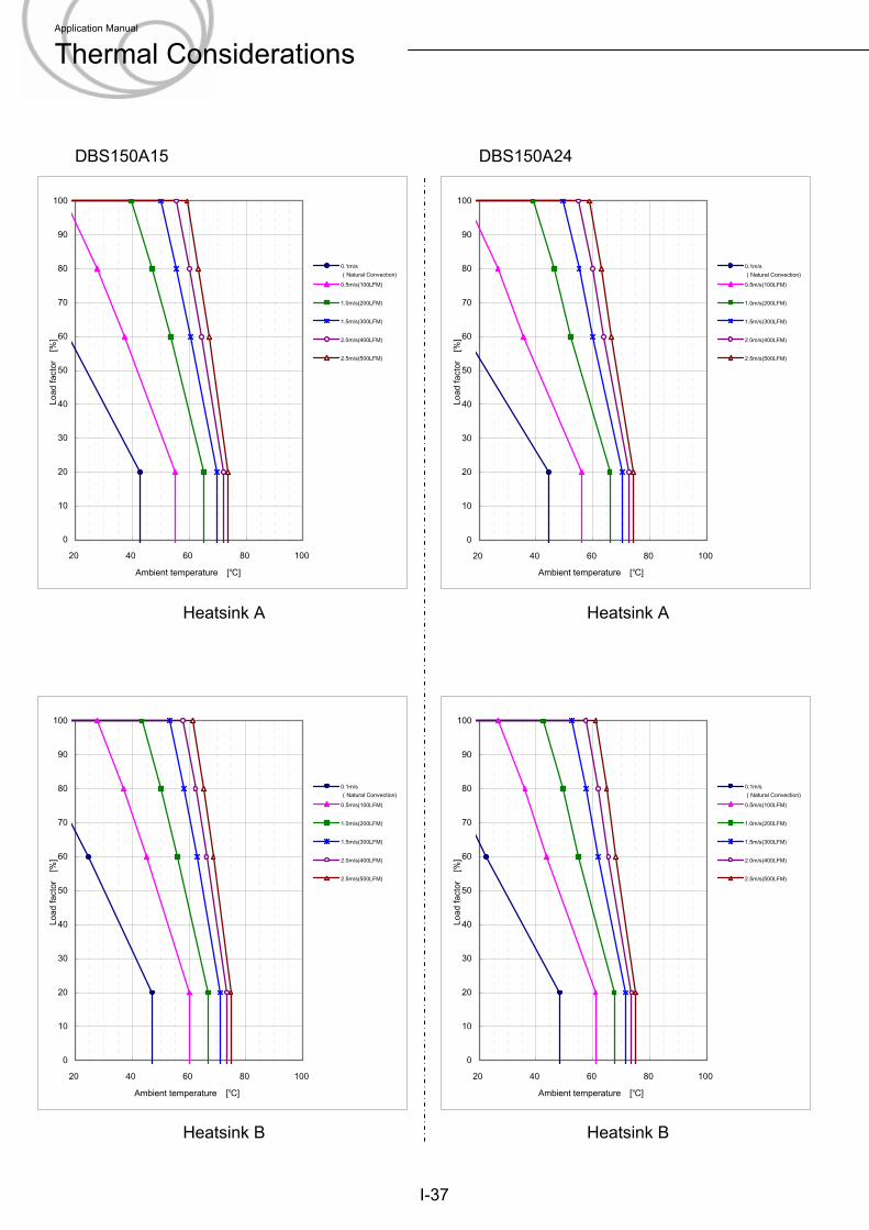
DBS150A15 DBS150A24
I-37
Heatsink A Heatsink A
Heatsink B Heatsink B
0
10
20
30
40
50
60
70
80
90
100
20 40 60 80 100
Ambient temperature [℃]
Load
fact
or
[%]
0.1m/s(Natural Convection)0.5m/s(100LFM)
1.0m/s(200LFM)
1.5m/s(300LFM)
2.0m/s(400LFM)
2.5m/s(500LFM)
0
10
20
30
40
50
60
70
80
90
100
20 40 60 80 100
Ambient temperature [℃]
Load
fact
or
[%]
0.1m/s(Natural Convection)0.5m/s(100LFM)
1.0m/s(200LFM)
1.5m/s(300LFM)
2.0m/s(400LFM)
2.5m/s(500LFM)
0
10
20
30
40
50
60
70
80
90
100
20 40 60 80 100
Ambient temperature [℃]
Load
fact
or
[%]
0.1m/s(Natural Convection)0.5m/s(100LFM)
1.0m/s(200LFM)
1.5m/s(300LFM)
2.0m/s(400LFM)
2.5m/s(500LFM)
0
10
20
30
40
50
60
70
80
90
100
20 40 60 80 100
Ambient temperature [℃]
Load
fact
or
[%]
0.1m/s(Natural Convection)0.5m/s(100LFM)
1.0m/s(200LFM)
1.5m/s(300LFM)
2.0m/s(400LFM)
2.5m/s(500LFM)
Application Manual
Thermal Considerations
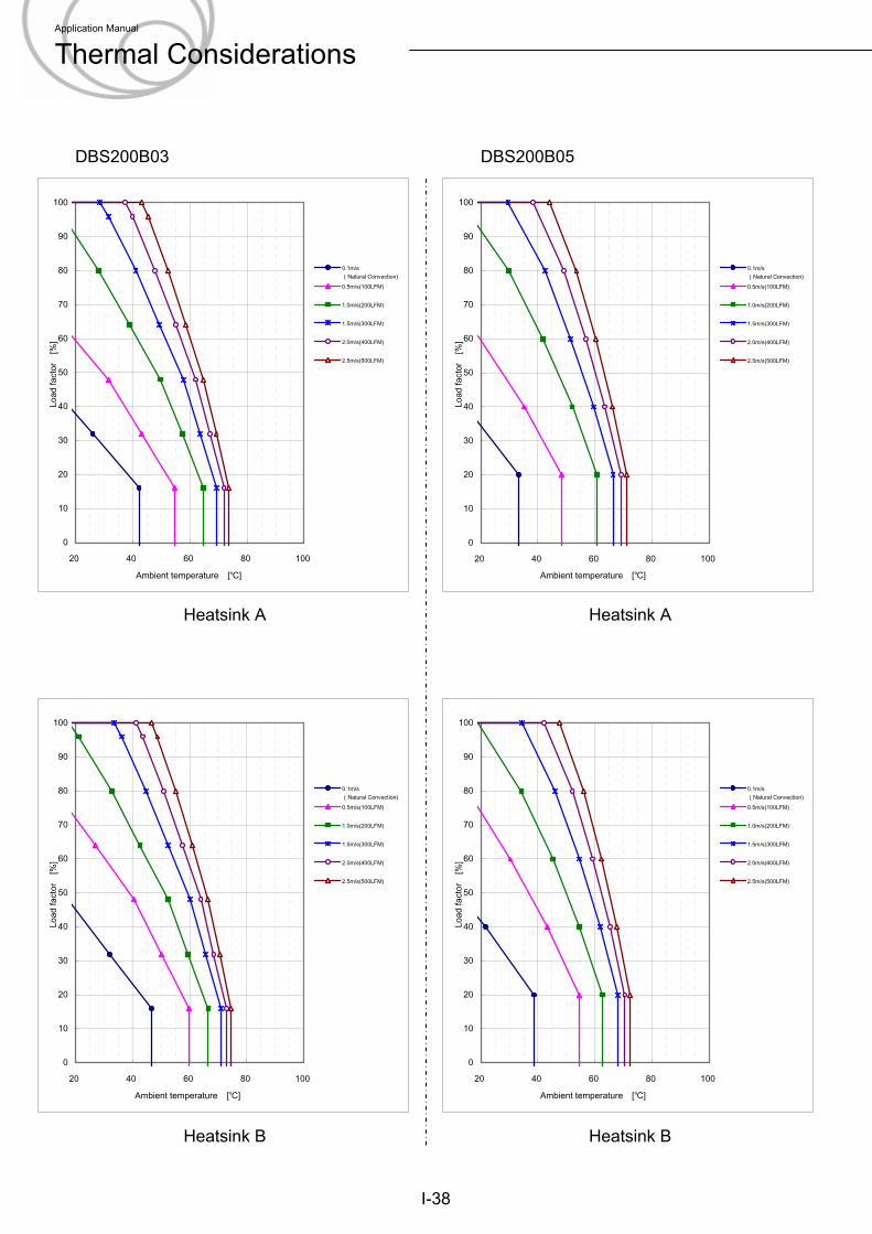
DBS200B03 DBS200B05
I-38
Heatsink A Heatsink A
Heatsink B Heatsink B
0
10
20
30
40
50
60
70
80
90
100
20 40 60 80 100
Ambient temperature [℃]
Load
fact
or
[%]
0.1m/s(Natural Convection)0.5m/s(100LFM)
1.0m/s(200LFM)
1.5m/s(300LFM)
2.0m/s(400LFM)
2.5m/s(500LFM)
0
10
20
30
40
50
60
70
80
90
100
20 40 60 80 100
Ambient temperature [℃]
Load
fact
or
[%]
0.1m/s(Natural Convection)0.5m/s(100LFM)
1.0m/s(200LFM)
1.5m/s(300LFM)
2.0m/s(400LFM)
2.5m/s(500LFM)
0
10
20
30
40
50
60
70
80
90
100
20 40 60 80 100
Ambient temperature [℃]
Load
fact
or
[%]
0.1m/s(Natural Convection)0.5m/s(100LFM)
1.0m/s(200LFM)
1.5m/s(300LFM)
2.0m/s(400LFM)
2.5m/s(500LFM)
0
10
20
30
40
50
60
70
80
90
100
20 40 60 80 100
Ambient temperature [℃]
Load
fact
or
[%]
0.1m/s(Natural Convection)0.5m/s(100LFM)
1.0m/s(200LFM)
1.5m/s(300LFM)
2.0m/s(400LFM)
2.5m/s(500LFM)
Application Manual
Thermal Considerations
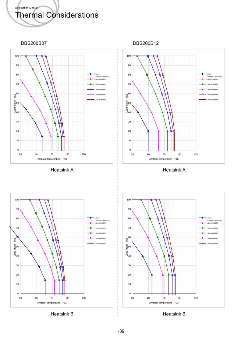
DBS200B07 DBS200B12
I-39
Heatsink A Heatsink A
Heatsink B Heatsink B
0
10
20
30
40
50
60
70
80
90
100
20 40 60 80 100
Ambient temperature [℃]
Load
fact
or
[%]
0.1m/s(Natural Convection)0.5m/s(100LFM)
1.0m/s(200LFM)
1.5m/s(300LFM)
2.0m/s(400LFM)
2.5m/s(500LFM)
0
10
20
30
40
50
60
70
80
90
100
20 40 60 80 100
Ambient temperature [℃]
Load
fact
or
[%]
0.1m/s(Natural Convection)0.5m/s(100LFM)
1.0m/s(200LFM)
1.5m/s(300LFM)
2.0m/s(400LFM)
2.5m/s(500LFM)
0
10
20
30
40
50
60
70
80
90
100
20 40 60 80 100
Ambient temperature [℃]
Load
fact
or
[%]
0.1m/s(Natural Convection)0.5m/s(100LFM)
1.0m/s(200LFM)
1.5m/s(300LFM)
2.0m/s(400LFM)
2.5m/s(500LFM)
0
10
20
30
40
50
60
70
80
90
100
20 40 60 80 100
Ambient temperature [℃]
Load
fact
or
[%]
0.1m/s(Natural Convection)0.5m/s(100LFM)
1.0m/s(200LFM)
1.5m/s(300LFM)
2.0m/s(400LFM)
2.5m/s(500LFM)
Application Manual
Thermal Considerations
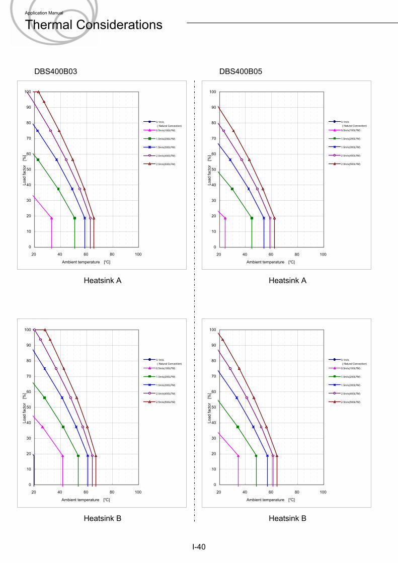
DBS400B03 DBS400B05
I-40
Heatsink A Heatsink A
Heatsink B Heatsink B
0
10
20
30
40
50
60
70
80
90
100
20 40 60 80 100
Ambient temperature [℃]
Load
fact
or
[%]
0.1m/s(Natural Convection)0.5m/s(100LFM)
1.0m/s(200LFM)
1.5m/s(300LFM)
2.0m/s(400LFM)
2.5m/s(500LFM)
0
10
20
30
40
50
60
70
80
90
100
20 40 60 80 100
Ambient temperature [℃]
Load
fact
or
[%]
0.1m/s(Natural Convection)0.5m/s(100LFM)
1.0m/s(200LFM)
1.5m/s(300LFM)
2.0m/s(400LFM)
2.5m/s(500LFM)
0
10
20
30
40
50
60
70
80
90
100
20 40 60 80 100
Ambient temperature [℃]
Load
fact
or
[%]
0.1m/s(Natural Convection)0.5m/s(100LFM)
1.0m/s(200LFM)
1.5m/s(300LFM)
2.0m/s(400LFM)
2.5m/s(500LFM)
0
10
20
30
40
50
60
70
80
90
100
20 40 60 80 100
Ambient temperature [℃]
Load
fact
or
[%]
0.1m/s(Natural Convection)0.5m/s(100LFM)
1.0m/s(200LFM)
1.5m/s(300LFM)
2.0m/s(400LFM)
2.5m/s(500LFM)
Application Manual
Thermal Considerations
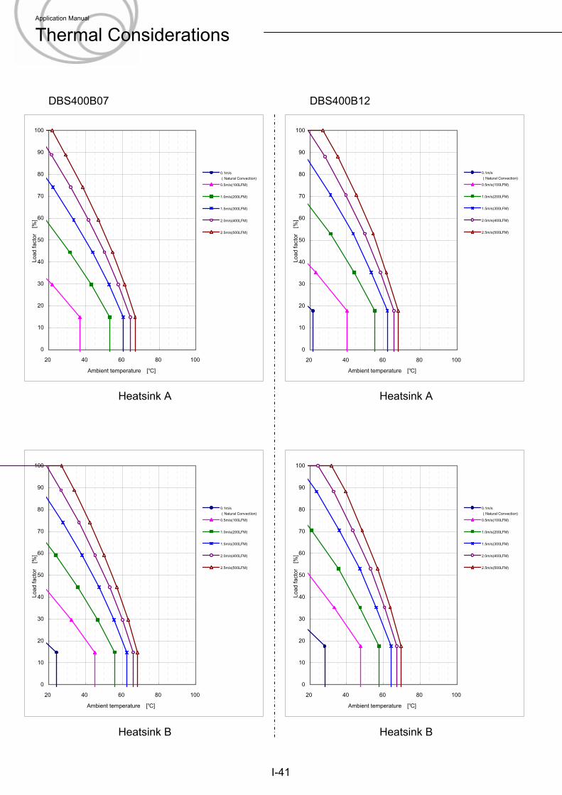
DBS400B07 DBS400B12
I-41
Heatsink A Heatsink A
Heatsink B Heatsink B
0
10
20
30
40
50
60
70
80
90
100
20 40 60 80 100
Ambient temperature [℃]
Load
fact
or
[%]
0.1m/s(Natural Convection)0.5m/s(100LFM)
1.0m/s(200LFM)
1.5m/s(300LFM)
2.0m/s(400LFM)
2.5m/s(500LFM)
0
10
20
30
40
50
60
70
80
90
100
20 40 60 80 100
Ambient temperature [℃]
Load
fact
or
[%]
0.1m/s(Natural Convection)0.5m/s(100LFM)
1.0m/s(200LFM)
1.5m/s(300LFM)
2.0m/s(400LFM)
2.5m/s(500LFM)
0
10
20
30
40
50
60
70
80
90
100
20 40 60 80 100
Ambient temperature [℃]
Load
fact
or
[%]
0.1m/s(Natural Convection)0.5m/s(100LFM)
1.0m/s(200LFM)
1.5m/s(300LFM)
2.0m/s(400LFM)
2.5m/s(500LFM)
0
10
20
30
40
50
60
70
80
90
100
20 40 60 80 100
Ambient temperature [℃]
Load
fact
or
[%]
0.1m/s(Natural Convection)0.5m/s(100LFM)
1.0m/s(200LFM)
1.5m/s(300LFM)
2.0m/s(400LFM)
2.5m/s(500LFM)
Application Manual
Thermal Considerations
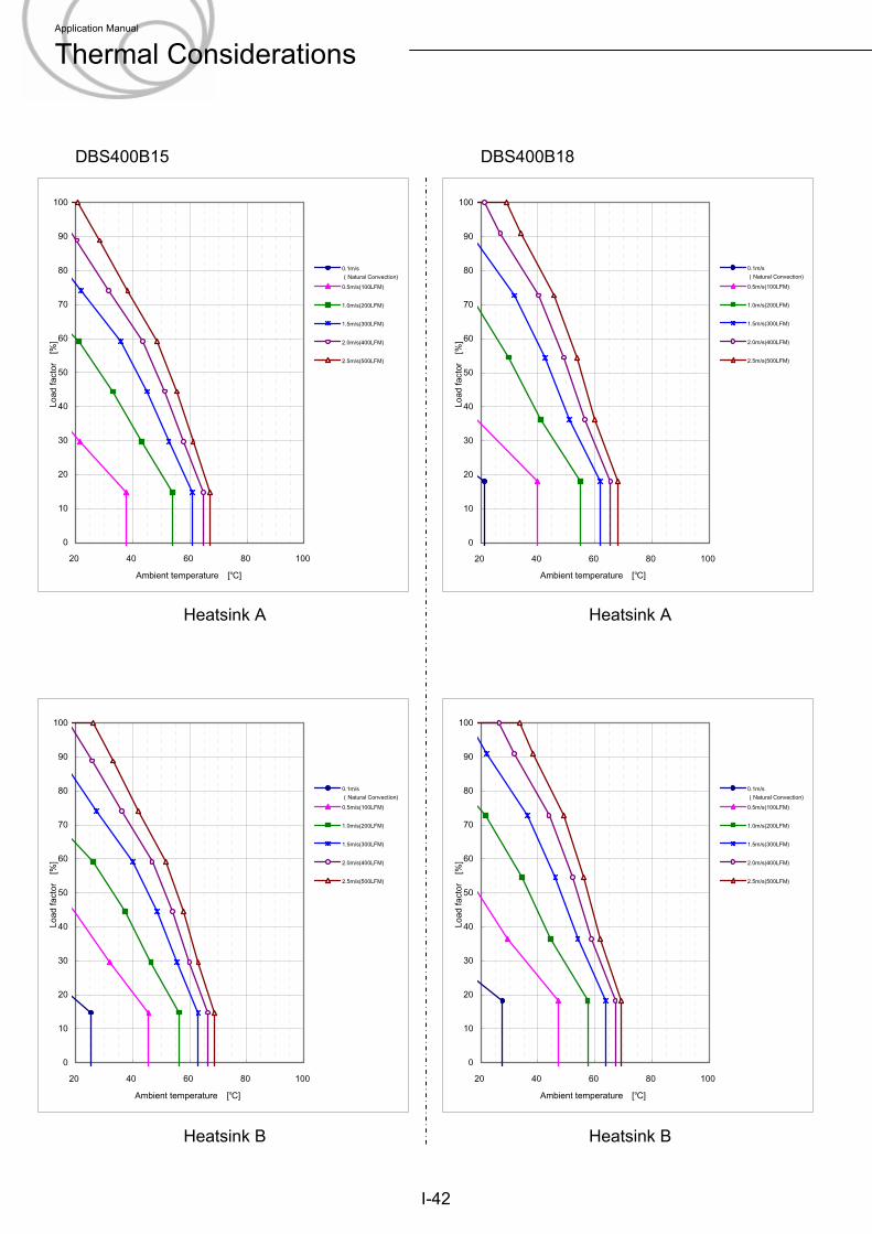
DBS400B15 DBS400B18
I-42
Heatsink A Heatsink A
Heatsink B Heatsink B
0
10
20
30
40
50
60
70
80
90
100
20 40 60 80 100
Ambient temperature [℃]
Load
fact
or
[%]
0.1m/s(Natural Convection)0.5m/s(100LFM)
1.0m/s(200LFM)
1.5m/s(300LFM)
2.0m/s(400LFM)
2.5m/s(500LFM)
0
10
20
30
40
50
60
70
80
90
100
20 40 60 80 100
Ambient temperature [℃]
Load
fact
or
[%]
0.1m/s(Natural Convection)0.5m/s(100LFM)
1.0m/s(200LFM)
1.5m/s(300LFM)
2.0m/s(400LFM)
2.5m/s(500LFM)
0
10
20
30
40
50
60
70
80
90
100
20 40 60 80 100
Ambient temperature [℃]
Load
fact
or
[%]
0.1m/s(Natural Convection)0.5m/s(100LFM)
1.0m/s(200LFM)
1.5m/s(300LFM)
2.0m/s(400LFM)
2.5m/s(500LFM)
0
10
20
30
40
50
60
70
80
90
100
20 40 60 80 100
Ambient temperature [℃]
Load
fact
or
[%]
0.1m/s(Natural Convection)0.5m/s(100LFM)
1.0m/s(200LFM)
1.5m/s(300LFM)
2.0m/s(400LFM)
2.5m/s(500LFM)
Application Manual
Thermal Considerations
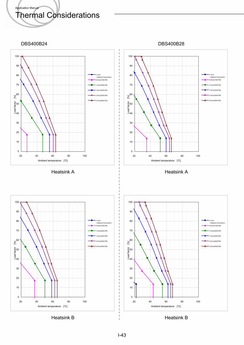
DBS400B24 DBS400B28
I-43
Heatsink A Heatsink A
Heatsink B Heatsink B
0
10
20
30
40
50
60
70
80
90
100
20 40 60 80 100
Ambient temperature [℃]
Load
fact
or
[%]
0.1m/s(Natural Convection)0.5m/s(100LFM)
1.0m/s(200LFM)
1.5m/s(300LFM)
2.0m/s(400LFM)
2.5m/s(500LFM)
0
10
20
30
40
50
60
70
80
90
100
20 40 60 80 100
Ambient temperature [℃]
Load
fact
or
[%]
0.1m/s(Natural Convection)0.5m/s(100LFM)
1.0m/s(200LFM)
1.5m/s(300LFM)
2.0m/s(400LFM)
2.5m/s(500LFM)
0
10
20
30
40
50
60
70
80
90
100
20 40 60 80 100
Ambient temperature [℃]
Load
fact
or
[%]
0.1m/s(Natural Convection)0.5m/s(100LFM)
1.0m/s(200LFM)
1.5m/s(300LFM)
2.0m/s(400LFM)
2.5m/s(500LFM)
0
10
20
30
40
50
60
70
80
90
100
20 40 60 80 100
Ambient temperature [℃]
Load
fact
or
[%]
0.1m/s(Natural Convection)0.5m/s(100LFM)
1.0m/s(200LFM)
1.5m/s(300LFM)
2.0m/s(400LFM)
2.5m/s(500LFM)
Application Manual
Thermal Considerations