Embed Size (px)
Citation preview
Thermal network camerasPerformance considerations for intelligent video
WHITE PAPER

Table of contents
1. Introduction 3
2. Benefits of integrating intelligent video applications 3
2.1 Motion detection 3
2.2 Tripwire detection 4
3. Definition of detection range according to Johnson’s criteria 4
4. Nomographs 5
5. Environmental considerations 6
5.1 Absorption 6
5.2 Scattering 6
5.3 Fog, smog, and haze 6
5.4 Rain and snow 6
6. Conclusion 7
7. Useful links 7
3
1. Introduction Thermal cameras have many advantages, such as allowing users to detect people, objects and incidents in complete darkness and difficult conditions such as smoke, haze, dust and light fog. Eliminating the need for flood lights, they reduce light pollution. In addition, a thermal camera is a reliable platform for integrating intelligent software applications. A conventional network camera reacts to changes in the captured image and can, for example, be disturbed by shades and back lighting. A thermal network camera detects the thermal radiation from the object, which is a more static parameter compared to visual changes in an image.
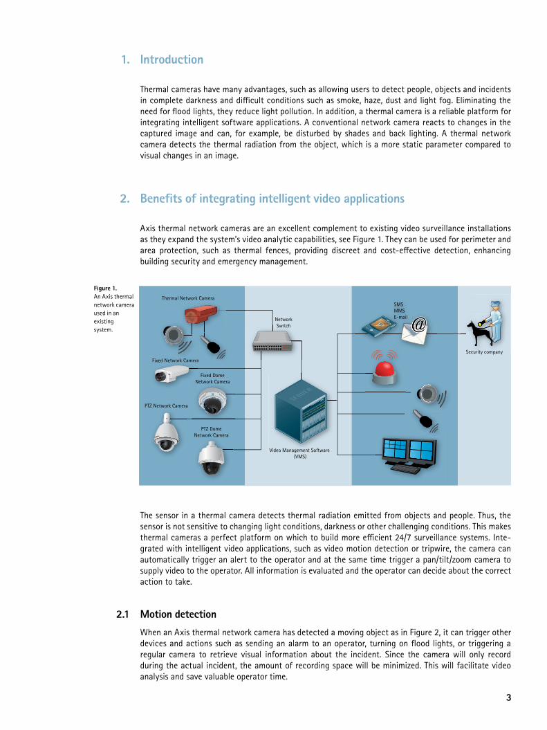
2. Benefits of integrating intelligent video applications Axis thermal network cameras are an excellent complement to existing video surveillance installations as they expand the system’s video analytic capabilities, see Figure 1. They can be used for perimeter and area protection, such as thermal fences, providing discreet and cost-effective detection, enhancing building security and emergency management.
The sensor in a thermal camera detects thermal radiation emitted from objects and people. Thus, the sensor is not sensitive to changing light conditions, darkness or other challenging conditions. This makes thermal cameras a perfect platform on which to build more efficient 24/7 surveillance systems. Inte-grated with intelligent video applications, such as video motion detection or tripwire, the camera can automatically trigger an alert to the operator and at the same time trigger a pan/tilt/zoom camera to supply video to the operator. All information is evaluated and the operator can decide about the correct action to take.
2.1 Motion detection
When an Axis thermal network camera has detected a moving object as in Figure 2, it can trigger other devices and actions such as sending an alarm to an operator, turning on flood lights, or triggering a regular camera to retrieve visual information about the incident. Since the camera will only record during the actual incident, the amount of recording space will be minimized. This will facilitate video analysis and save valuable operator time.
Thermal Network CameraSMSMMSE-mail
Security company
NetworkSwitch
Video Management Software (VMS)
Fixed Network Camera
PTZ Network Camera
Fixed DomeNetwork Camera
PTZ DomeNetwork Camera
Fixed Netw
NN
work Camerawork Cameraeraera
Figure 1. An Axis thermal network camera used in an existing system.

4
2.2 Tripwire detection
A virtual line can be placed in the image of the thermal network camera, see Figure 3. The virtual line will act as a tripwire. If an object crosses the virtual tripwire, the thermal network camera can trigger another camera as in the motion detection example.
Integrating thermal network cameras with intelligent video applications has many advantages. However, in order to get the optimum use of thermal network cameras other things will have to be considered than when using conventional network cameras.
Definition of detection range, number of pixels across the object, and the surrounding environment need to be considered. These parameters are of special importance when integrating with an intelligent video application.
3. Definition of detection range according to Johnson’s criteria The resolution required to detect an object is stated in pixels and is determined by means of Johnson’s criteria. John Johnson, a US military scientist, developed this method for predicting the performance of sensor systems during the 1950’s. An object can be a person, typically defined with a critical dimension of 0.75 m (2.46 ft.) or a vehicle, typically defined with a critical dimension of 2.3 m (7.55 ft.). Johnson measured the ability of observers to identify scale model targets under various conditions, and came up with criteria for the minimum required resolution. These criteria provide a 50 % probability of an observer distinguishing an object at the specified level. For a thermal sensor, the temperature difference between the object and its background needs to be at least 2 °C. The levels of Johnson’s criteria used for Axis thermal network cameras are as follows:
Figure 2: Example of an Axis thermal camera used for motion detection.
Figure 3: Example of a virtual tripwire.

5
> At least 1.5 pixels are needed for detection, that is, the observer can see that an object is present.
> At least 6 pixels are needed for recognition, that is, the observer can distinguish the object, for example, a person in front of a fence.
> At least 12 pixels are needed for identification, that is, the observer can distinguish an object and object characteristics, for example, a person holding a crowbar in his hand.
Johnson’s criteria were developed under the assumption that visible information was processed by a human observer. If the information instead is processed by an application algorithm there will be specific requirements on the number of pixels needed on the target for reliable operation. All intelligent video software algorithms need to work with a certain number of pixels. The exact number may vary but as a as a rule of thumb at least 6 pixels across the object are required, which is the same as recognition according to Johnson’s criteria. Even if a human observer would be able to detect the object, the application algorithm often needs a larger amount of pixels at a given detection range to work properly. To find out the available number of pixels at a given range, a nomograph is used.
4. Nomographs A nomograph is a two-dimensional diagram explaining the relation between the focal length of the lens, the number of pixels across the object, and the range. For example, if the number of pixels required and the distance at which an object needs to be recognized are known, it is possible to calculate which lens or camera to use. Equally, if the camera and the number of pixels required are known, the distance at which the camera can detect an object is indicated by the nomograph.
For example, take an AXIS Q1921/-e Thermal Network Camera with a 60 mm lens pointed at a person with a critical dimension of 0.75 m (2.46 ft.). The nomograph in Figure 4 shows that the object will be recognizable at 300 m (328 yd.) and 6 pixels across the object (A). If only detection is required, the range will instead be 1 200 m (1 312 yd.) and 1.5 pixels across the object (B).
Figure 4: Example of a nomograph.
1,0
10,0
100 1000
10 mm
19 mm
35 mm
60 mm
Nomograph - AXIS Q1921/-eLong distance
Focal length
Distance to target (m)
Pix
els
acro
ss 0
.75
m t
arge
t
(A)
(B)

6
5. Environmental considerations It is essential to remember that Johnson’s criteria are valid only in ideal conditions. The weather conditions on site will affect the thermal radiation emitted from the object and decrease the effective detection range. The detection range used in the nomographs above ideally requires a temperature difference of 2 °C between the targeted object and the background. This section will further explain how environmental factors will influence thermal camera performance.
Environmental factors that affect the thermal camera include weather conditions and the temperature difference between the object and its background. An object with almost the same temperature as the background, such as a body on a hot summer day, is harder to distinguish from its background than an object with a greater temperature difference, such as a car with a running engine on a cold winter day.
The two most important environmental factors that affect the image of an object in the camera are absorption and scattering. They reduce the thermal radiation that reaches the camera, thereby reducing the distance at which the camera can detect an object. Scattering has a greater effect on the loss of thermal energy than absorption.
5.1 Absorption
Water vapor (H2O) and carbon dioxide (CO2) in the air are the primary causes of absorption. During absorption, the heat radiated from the object is absorbed by water vapor and carbon dioxide and loses some of its energy before reaching the camera
The water vapor content of the air affects image quality even in sunny and clear weather. In winter, if all other weather conditions are the same, the water vapor content of the air is lower than in summer. Since water vapor content is lower, less thermal radiation is absorbed by the water molecules, allowing more thermal radiation to reach the thermal network camera and resulting in better image quality when compared to a summer day.
5.2 Scattering
During scattering, the thermal radiation from the object is dispersed when it hits particles in the air. The loss of radiation is directly related to the size and concentration of the particles, droplets or crystals that constitute polluting, condensing or precipitating conditions such as smog, fog, rain or snow.
5.3 Fog, smog, and haze
Fog appears when water vapor in the air condenses into water droplets. The droplet sizes vary with different kinds of fog. In dense fog, the water droplets are bigger due to accretion, thus scattering thermal radiation more than light fog. Also, fog scatters thermal radiation to a larger extent than both smog and haze because of the greater size and concentration of its water droplets.
5.4 Rain and snow
Even though rain drops are larger than fog droplets, their concentration is lower. This means that rain does not scatter thermal radiation as much as fog does. The level of scattering during snow is some-where in between the range of fog and rain. Sleet or wet snow has a scattering level more similar to rain, whereas dry snow is more similar to fog.

7
Weather conditions and attenuation
Heavy rain Light rain Urban pollution Dense fog Fog
11 dB/km 4 dB/km 0.5 dB/km 80 dB/km 10 dB/km
17.6 dB/mile 6.4 dB/mile 0.8 dB/mile 128 dB/mile 16 dB/mile
For example, an AXIS Q1921/-e Thermal Network Camera with a 60 mm lens as used in the earlier ex-ample (Figure 4.) will have a range of 300 m (328 yd.) with 6 pixels on target a clear day. A foggy day the attenuation will be 10 dB/km or 1 dB/100 m, resulting in an attenuation of 3 dB in total. The 3 dB attenuation means that only 50 % of the emitted energy from the object will reach the thermal sensor, degrading camera performance and the reliability of integrated Intelligent Video applications.
Therefore, installations where one single camera is working close to its maximum performance should be avoided. A better option is to use several cameras to cover the given distance. This will safe-guard reliable operation by meeting the required amount of pixels on target and also reassure that the emitted energy from the object is sufficient.
6. Conclusion Being the market leader, Axis has the largest partnership program and can offer the widest range of third-party intelligent video applications. This document presents different factors to consider when integrating Axis thermal network cameras with intelligent video applications. Using Johnson’s criteria as a starting point to determine the required number of pixels at a certain range is crucial and the corre-sponding software requirements should always be investigated.
Weather conditions constitute another factor that will affect the performance of the installation. Even though the number of pixels meets the requirements, the temperature difference between the back-ground and the object might not be enough to reassure reliable application operation. For example, the attenuation should be taken into consideration if a thermal network camera is to be installed where dense fog is frequent.
For maximum performance, always test the camera and the intelligent application in the actual environ-ment where it is to be used and to avoid performance and reliability problems.
7. Useful links For more information, see the following links:
> Axis Communications – ‘Axis thermal network cameras – High-quality detection in dark and challenging conditions’: www.axis.com/files/brochure/bc_thermal_40618_en_1009_lo.pdf
> Axis Communications – ‘Some like it hot – Thermal cameras in surveillance’: www.axis.com/files/whitepaper/wp_axis_thermal_cameras_en_37661_0912_lo.pdf
> Axis Communications – ‘Axis thermal network cameras – Reliable detection, 24 hours a day, seven days a week’: www.axis.com/products/video/camera/thermal/technology.htm

www.axis.com
4526
6/EN
/R1/
1111
About Axis CommunicationsAxis is an IT company offering network video solutions for professional installations. The company is the global market leader in network video, driving the ongoing shift from analog to digital video surveillance. Axis products and solutions focus on security surveillance and remote monitoring, and are based on innovative, open technology platforms.Axis is a Swedish-based company, operating worldwide with offices in more than 20 countries and cooperating with partners in more than 70 countries. Founded in 1984, Axis is listed on the NASDAQ OMX Stockholm under the ticker AXIS. For more information about Axis, please visit our website at www.axis.com.
©2011 Axis Communications AB. AXIS COMMUNICATIONS, AXIS, ETRAX, ARTPEC and VAPIX are registered trademarks or trademark applications of Axis AB in various jurisdictions. All other company names and products are trademarks or registered trademarks of their respective companies. We reserve the right to introduce modifications without notice.