Embed Size (px)
DESCRIPTION
flexure design
Citation preview

Flexural design for
ultimate loading
Fawad Muzaffar M.Sc. Structures (Stanford University)
Ph.D. Structures (Stanford University)
Civil Engineering
Department

Specified Load Factors
Fawad Muzaffar 2
Load Factors as Specified by ACI-318
Note: Refer to ACI 318-08 for exceptions.

Specified Values of Strength Reduction Factors
• ACI 318-08
• AASHTO
Fawad Muzaffar 3

The Unified Approach for Calculation of Strength Reduction Factors, 𝜙
• Nominal moment capacity is reached when 𝜀𝑐 = 0.003.
• The behavior is tension controlled (or ductile) when 𝜀𝑡 = 0.005.
• If 𝜀𝑡 is small ( as is the case
Fawad Muzaffar 4
for axially loaded members, the behavior of the member will be brittle).
• If 𝜀𝑡 < 𝜀𝑦, the behavior is specified as compression controlled.
• Note: 𝜀𝑡 values above for 𝜀𝑐 = 0.003 can be related to 𝜌/𝜌𝑏 ratios. e.g. 𝜀𝑡 = 0.005 would result in 𝜌 𝜌𝑏 = 0.63

The Unified Approach for Calculation of Strength Reduction Factors, 𝜙
Fawad Muzaffar 5
• Reduction factor as a function of 𝜀𝑡
• Note: The greater the 𝜀𝑡, the more economical will the section be.

Calculation of Nominal Moment-The Strain Compatibility Approach
Fawad Muzaffar 6
• Increase in lateral load results in progressive increase of tensile strain, ultimately cracking at bottom. This happens when
• After M>Mcr significantly , the member starts to behave like reinforced concrete member.
• Before cracking, stresses in concrete at the CGS level have to reduce to zero (i.e. decompression stage)

Calculation of Nominal Moment-The Strain Compatibility Approach
• Strain in Prestressing Steel at Different Stages – Due to Prestressing:
– At Decompression:
– At Ultimate Load:
– Consequently:
– The corresponding stress in prestressing steel can then be evaluated.
• Compression in Concrete
Fawad Muzaffar 7
Calculation of Nominal Moment-The Strain Compatibility Approach
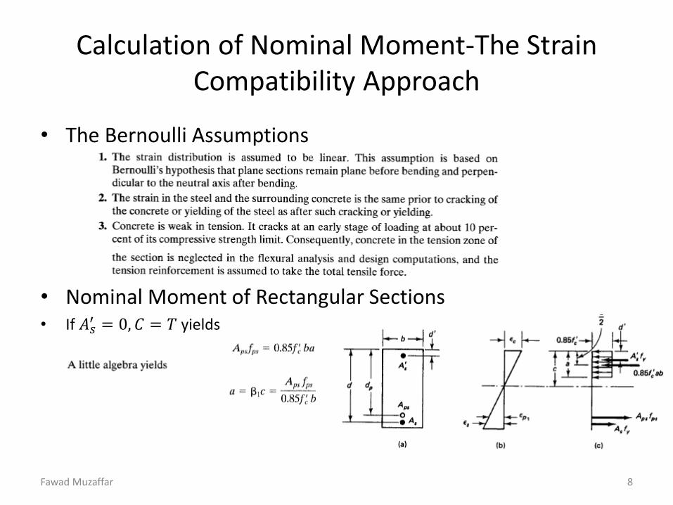
• The Bernoulli Assumptions
• Nominal Moment of Rectangular Sections • If 𝐴𝑠
′ = 0, 𝐶 = 𝑇 yields
Fawad Muzaffar 8
Calculation of Nominal Moment-The Strain Compatibility Approach
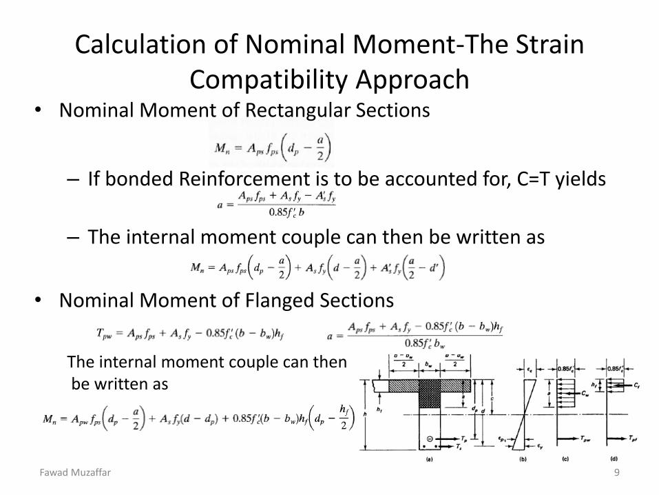
• Nominal Moment of Rectangular Sections
– If bonded Reinforcement is to be accounted for, C=T yields
– The internal moment couple can then be written as
• Nominal Moment of Flanged Sections
The internal moment couple can then be written as
Fawad Muzaffar 9

Calculation of Nominal Moment-The Strain Compatibility Approach
• The Solution Algorithm for Rectangular Sections
– Unknowns: 𝑓𝑝𝑠, 𝑓𝑠 & c. Goal: Calculate Mn
– Assume c Calculate 𝜀𝑠 & 𝜀𝑝𝑠 Calculate 𝑓𝑝𝑠, 𝑓𝑠 Evaluate c from
Σ𝐹𝑥 = 0 Check c Iterate if Necessary
or
– Express: 𝜀𝑠 = 𝑓(𝑐) & 𝜀𝑝𝑠 = 𝑓(𝑐) Calculate 𝑓𝑝𝑠, 𝑓𝑠 Constitute
Nonlinear Equation by writing Σ𝐹𝑥 = 0 Solve the nonlinear equation to evaluate c.
• The Solution Algorithm for Flanged Sections – Assume a<tf Check assumption by writing Σ𝐹𝑥 = 0 Analyze as
Rectangular Section if assumption is true.
– If a>tf Correct the assumption and analyze
section by adopting a T section.
Fawad Muzaffar 10

Calculation of Nominal Moment-The Approximate Approach
• Approximate Evaluation is allowed by ACI 318 if
– Bonded Tendons
– Unbonded Tendons
Fawad Muzaffar 11

Design for Ultimate Strength – Reinforcement Limits
• Minimum Values of Reinforcement Index – Definition
– If percentage of reinforcement is
too small, section will fail premat-
-urely as soon as Mu>Mcr.
– The total amount of pre-stressed &
non-prestressed reinforcement req-
uired by ACI should result in
𝑀𝑢 ≥ 1.2 𝑀𝑐𝑟
Exception: If Mn > 2 ×𝑀𝑢 and Vn > 2 × 𝑉𝑢
Fawad Muzaffar 12

Design for Ultimate Strength – Reinforcement Limits
• Minimum area of bonded non-prestressed reinforcement in beams should be calculated using
• Maximum Reinforcement – If percentage of longitudinal reinforcement is large enough, brittle
failure will result.
– To ensure ductile failure, ACI specifies that 𝜀𝑡 ≥ 0.005 at ultimate load.
– In prestressed members, it is not always possible to ensure an under-reinforced behavior because
i) Serviceability Requirements ii) Absence of yield plateau of prestressed steel
Fawad Muzaffar 13

Design for Ultimate Strength – Reinforcement Limits
• To ensure ductile behavior at ultimate load, the reinforcement index is limited to – For Rectangular Sections with Prestressing Steel only:
– For Rectangular Sections with + and –ve bonded Steel:
– For Flange Sections:
where
– Note that for rectangular section
Fawad Muzaffar 14

Design for Ultimate Strength – Reinforcement Limits
– For flange section
– For over-reinforced prestressed beams, section B.18.8.2 of the code specifies
– Use Empirical Relationship to evaluate Mn of Over reinforced Beams
i) Rectangular Section: ii) Flanged Section:
Fawad Muzaffar 15

Evaluation of Nominal Moment of Non-Bonded Prestressed Members
• Un-bonded Tendons – Un-grouted Tendons or Asphalt Coated Tendons.
– Stress Concentration do not exist at crack locations of un-bonded Tendons.
– A lesser number of wider cracks exist in un-bonded prestressed members.
– Bonded reinforcement is more important for members with un-bonded tendons as compared to bonded members.
– Bonded reinforcement contributes significantly to increasing the moment strength capacity of the section.
– The bonded reinforcement at the bottom will always be yielding at ultimate moment.
– The expressions presented for bonded prestressed members are equally applicable for evaluation of nominal moment of un-bonded members.
Fawad Muzaffar 16