Embed Size (px)
Citation preview

8901 Networked Single Door
Access Panel Installation Guide
8901 Access Control Panel Installation Guide
__________________________________________________________________________
_______________________________________________________________________________________________________________
2016-01-28 Design . Innovations Page 2 of 34
Item Description Page
1. Introduction P.3
2. Technical Specification P.5
3. System Deployment P.7
4. Detailed Pin Assignment P.9
5. Panel Configuration P.11
6. Sample Connection Circuits
- System
- Reader
- Electrical Lock
- Door Alarm
- Door Ajar
- Door Sensor
- Release Button
- Panel Tamper
P. 12
7. ACX.90 Integrated System Platform
- Installation on the computer
- Set up the communication with control panel
- Add the first cardholder with access right
- Enable Alarms in the control panels
P. 20

8901 Access Control Panel Installation Guide
__________________________________________________________________________
_______________________________________________________________________________________________________________
2016-01-28 Design . Innovations Page 3 of 34
1. Introduction
This document provides detailed description about the features, functions and setup of
ACX 8901 Control Panel.
A. Strength
Native TCP/IP on board, 10/100Mbps communication speed
Flexibility structure cabling, cat 5 cable, direct to hub or panel to panel daisy chain
wiring
Multi-threading program, transactions upload to database server less than 2 sec
under 50 panels
User defined 128 bits key for the data exchange between ACX 8901&8902 door
access panel to ACX COM Server, prevent the real data to be snooped and
simulated by other network point
User defined 128 bits key, scramble RS485 data exchange between ACX
8901&8902 door access panel and ACX reader, prevent reader data to be snooped
and copied
Work with ACX 2081 I/O module, save the wiring cost and increase the data
security (patented design)
Support 7 x card number format, each card number format has 3 x facility code
checking
Work with ACX LCD reader, display interactive message
Work with ACX emergency door open device
Supervised Monitor of the Door Sensor Input, Prevent trouble close and open
B. Features
32 bits microprocessor, 50MHz
External device short circuit protection
Thumbed protection
Recoverable fuse protection
Status LED represents operating status
Auto recover for the TCP/IP failure
Battery on board for memory retention, 3 years
Firmware can be on-line upgraded
Real time clock, less than 1 sec deviation daily
Twin card operation (100 couples)
Anti-passback
Two door interlock

8901 Access Control Panel Installation Guide
__________________________________________________________________________
_______________________________________________________________________________________________________________
2016-01-28 Design . Innovations Page 4 of 34
C. Panel Appearance

8901 Access Control Panel Installation Guide
__________________________________________________________________________
_______________________________________________________________________________________________________________
2016-01-28 Design . Innovations Page 5 of 34
2. Technical Specification
Specification 8901
Panel Inputs
- 1 x IN and 1 x OUT Wigand reader or;
- 1 x IN and 1 x OUT ACX scramble RS485 reader
- 1 x door sensor input
- 1 x request to exit input
- 1 x auxiliary input
- 1 x controller box tamper input
- 1 x ACX high security key open door device
- Power input monitoring : A.C. / D.C. / Backup Battery
- Work with ACX high security door emergency open device,
couple with random key switch & reset panel.
Panel Outputs
- 1 x E-Lock relay dry contact output, max. 10A current rating
- 1 x Alarm relay dry contact output, max. 3A current rating
- 1 x Door ajar TTL signal output, 5VDC output, 20mA
- 12.8VDC battery charging
Memory
- 38,000 cardholders, each card holder has 24 bytes content
- 45,000 swipe card records
- 800 events
PCB Dimension 120mm x 120mm x 12mm
Expansion 1 x RS485 serial port for expansion, software and hardware
interface to other system
Holidays 100 Holiday dates
Timezone
- 80 x access control time zone
- 1 x password time zone
- 1 x electric Lock time zone
- 1 x alarm time zone
- 1 x door ajar time zone
- 1 x request to exit time zone
- 1 x twin card operation time zone
All timezone can be assigned from Monday to Sunday and
Holiday, 4 intervals per day, time zone can be selected
globally or individually

8901 Access Control Panel Installation Guide
__________________________________________________________________________
_______________________________________________________________________________________________________________
2016-01-28 Design . Innovations Page 6 of 34
Password
- User password, timezone control
- Global password, key in the password through keypad
reader open door
- Duress password, open door but trigger alarm output
Communication - Panel to hub, CAT 5 cable (max. 100 meters)
- Panel to panel, daisy chain by CAT 5 cable (max. 100 meters)
No. of Panels Depends on IP address available
Backup Battery
- 12VDC, 7AH backup battery,
- provide at least 4 hours operation, excludes electric lock
power consumption
Operating Voltage - 220V, 5A input in AC.
- 12VDC, 3A output
Operating
Temperature 0° to 65° C
Operating humidity 0-95% relative humidity non-condensing
Wiegand Reader
- Communication: Wiegand
- Green / Red LED control
- Buzzer control
- Reader in 6 wires connection
- Max. cable length : 150m
ACX Reader
- Communication : RS485
- High Security scramble data encryption
- 7 x LED color control
- Buzzer Control
- Interactive message display for ACX LCD reader
- Reader in 4 wires connection
- Max. cable length : 1,200m

8901 Access Control Panel Installation Guide
__________________________________________________________________________
_______________________________________________________________________________________________________________
2016-01-28 Design . Innovations Page 7 of 34
3. System Deployment
There are three ways to connect panels. All of the panels communicate in TCP/IP protocol
with each other. CAT5 cable is used to connect the panel to the (LAN) Local Area Network or
connect the panels in Daisy Chain. RS 485 protocol is no longer used for inter-panel
communications so that the cost is reduced and the speed is increased. Multi-threading is
also used to speed up concurrent operations.
Pier to Pier
Daisy Chain
Pier to Pier + Daisy Chain
Local Area Network
. . . .
Pier to Pier
DATABASE and
SOFTWARE
PANEL PANELPANEL
TCP
/IP
TCP
/IP
TCP
/IP

8901 Access Control Panel Installation Guide
__________________________________________________________________________
_______________________________________________________________________________________________________________
2016-01-28 Design . Innovations Page 8 of 34
Local Area Network
. . . .
Daisy Chain
DATABASE and
SOFTWARE
PANEL
TCP
/IP
TCP/IP
PANELPANEL
Local Area Network
. . . .
Pier to Pier + Daisy Chain
DATABASE and
SOFTWARE
PANEL PANEL
TCP
/IP
TCP
/IP
PANEL
TCP/IP . . . .PANEL

8901 Access Control Panel Installation Guide
__________________________________________________________________________
_______________________________________________________________________________________________________________
2016-01-28 Design . Innovations Page 9 of 34
4. Detailed Pin Assignment
Connector Summary PIN Description
C1 Power Input 1 12VDC, 3ADC
2 Ground
C2
E-Lock Power
(12V, 1.5A)
1 Ground
2 Power
E-Lock Output
(Dry Contact)
3 COM
4 NC
5 NO
C3
Door Alarm Output
(Dry Contact)
1 COM
2 NC
3 NO
Door Ajar Output 4 Normal is 0VDC, Door Ajar 5VDC, 200mA output
C4
Door Sensor 1 Door Sensor
2 Ground
Release Button 3 Release button
4 Ground
C5
AUX INPUT 1 IN#1
2 Ground
Panel Tamper 3 Tamper
4 Ground
C6 RS485 Port
(Custom use)
1 RS485 (T+)
2 RS485 (T-)
3 RS485 (T+)
4 RS485 (T-)
C7 For Emergency Door
Open Device
1 Power Out (12VDC, 100mA)
2 Ground
3 Signal +
4 Signal -
C8 Power Status
1 DC Power
2 Backup Battery
3 A.C. Power
8901 Single Door TCP/IP Controller

8901 Access Control Panel Installation Guide
__________________________________________________________________________
_______________________________________________________________________________________________________________
2016-01-28 Design . Innovations Page 10 of 34
4 Ground
C9 OUT Reader
1 Green LED (ACK)
2 Buzzer
3 Data 0
4 Data 1
5 Reader Power (200mA)
6 Ground
7 RS485 (T+) ACX RS485 reader only
8 RS485 (T-) ACX RS485 reader only
C10 IN Reader
1 Green LED (ACK)
2 Buzzer
3 Data 0
4 Data 1
5 Reader Power (200mA)
6 Ground
7 RS485 (T+) ACX RS485 reader only
8 RS485 (T-) ACX RS485 reader only
RJ45 2 Ports TCP/IP Switch 1
Connect to TCP/IP switch or next Panel 2

8901 Access Control Panel Installation Guide
__________________________________________________________________________
_______________________________________________________________________________________________________________
2016-01-28 Design . Innovations Page 11 of 34
5. Panel Configuration
Panel Address
1. Go to the IP Config folder under the Installation folder (Normally C:\Program Files
(x86)\ACX\X.90 Access Control System\Set IP Config). Open the IP Configuration utility
program.
2. Click “Scan” button.
3. Select the device and modify the IP Address or other parameters. Input the PWD and Click
“Set” button to download configuration to the board.
Remark: The Default Key is 123456

8901 Access Control Panel Installation Guide
__________________________________________________________________________
_______________________________________________________________________________________________________________
2016-01-28 Design . Innovations Page 12 of 34
6. Sample Connection Circuits
A. System
Daisy Chain
CONTROL PANEL
Input
Readers
Door Sensor
Release Button
Key Switch
Power Status
Panel Tampering
AUX Input
Output
Reader Feedback
E-Lock
Alarms
Door Ajar SignalCom
municatio
n
Local Area Network (LAN)
CONTROL PANEL
Da
isy C
ha
in

8901 Access Control Panel Installation Guide
__________________________________________________________________________
_______________________________________________________________________________________________________________
2016-01-28 Design . Innovations Page 13 of 34
B. Reader
Reader: C9, C10
Wire Color:
1. Orange Green LED (ACK)
2. Yellow Buzzer
3. Green Data 0
4. White Data 1
5. Red Reader Power
6. Black Ground
7. Purple RS485 (T+)
8. Grey RS485 (T-)
Wiegand Reader
1 2 3 4 5 6 7 8
Wiegand Reader
ACX Scramble RS485 Reader
(Improved Security)
1 2 3 4 5 6 7 8
ScrambleRS 485 Reader

8901 Access Control Panel Installation Guide
__________________________________________________________________________
_______________________________________________________________________________________________________________
2016-01-28 Design . Innovations Page 14 of 34
C. Electrical Lock
E-Lock: C2
Pin Assignment:
1 Ground
2 Power
3 COM
4 NC
5 NO
Normally Closed with Power on
Panel
E-Lock+ -
5 4 3 2 1
Normally Open with Power on
Panel
E-Lock+ -
5 4 3 2 1
Normally Closed with External
Power
E-Lo
ck+
-
External Power
5 4 3 2 1
ExternalGround
Normally Open with External
Power
E-Lo
ck+
-
External Power
5 4 3 2 1
ExternalGround

8901 Access Control Panel Installation Guide
__________________________________________________________________________
_______________________________________________________________________________________________________________
2016-01-28 Design . Innovations Page 15 of 34
D. Door Alarm (Dry Contact)
Alarm: C3
Pin Assignment:
1 COM
2 NC
3 NO
4 Normal is 0VDC, Door Ajar 5VDC, 20mA output
Normally Open with External
Power
4 3 2 1
Alarm Device
+-
External Power
ExternalGround
Normally Closed with External
Power
4 3 2 1
Alarm Device
+-
External Power
ExternalGround

8901 Access Control Panel Installation Guide
__________________________________________________________________________
_______________________________________________________________________________________________________________
2016-01-28 Design . Innovations Page 16 of 34
E. Door Ajar Output
Door Ajar: C3
Pin Assignment:
1 COM
2 NC
3 NO
4 Normal is 0VDC, Door Ajar 5VDC, 20mA output
Connect to LED indication
4 3 2 1
PanelGround
LED
8901 Access Control Panel Installation Guide
__________________________________________________________________________
_______________________________________________________________________________________________________________
2016-01-28 Design . Innovations Page 17 of 34
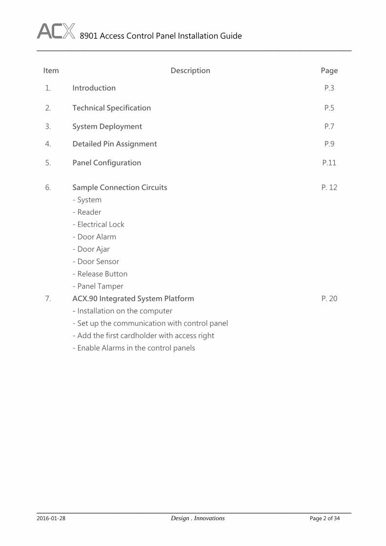
F. Door Sensor and Release Button Input
Door Sensor and Release Button:
C4
Pin Assignment:
1 Door Sensor
2 Ground
3 Release button
4 Ground
Connect the Sensor Input
4 3 2 1
Re
lease
Bu
tton
Do
or Se
nso
r

8901 Access Control Panel Installation Guide
__________________________________________________________________________
_______________________________________________________________________________________________________________
2016-01-28 Design . Innovations Page 18 of 34
G. Panel Tamper
Panel Tamper: C5
Pin Assignment:
1 Door Sensor
2 Ground
3 Release button
4 Ground
Connect the Sensor Input
4 3 2 1
Normal is Close
8901 Access Control Panel Installation Guide
__________________________________________________________________________
_______________________________________________________________________________________________________________
2016-01-28 Design . Innovations Page 19 of 34
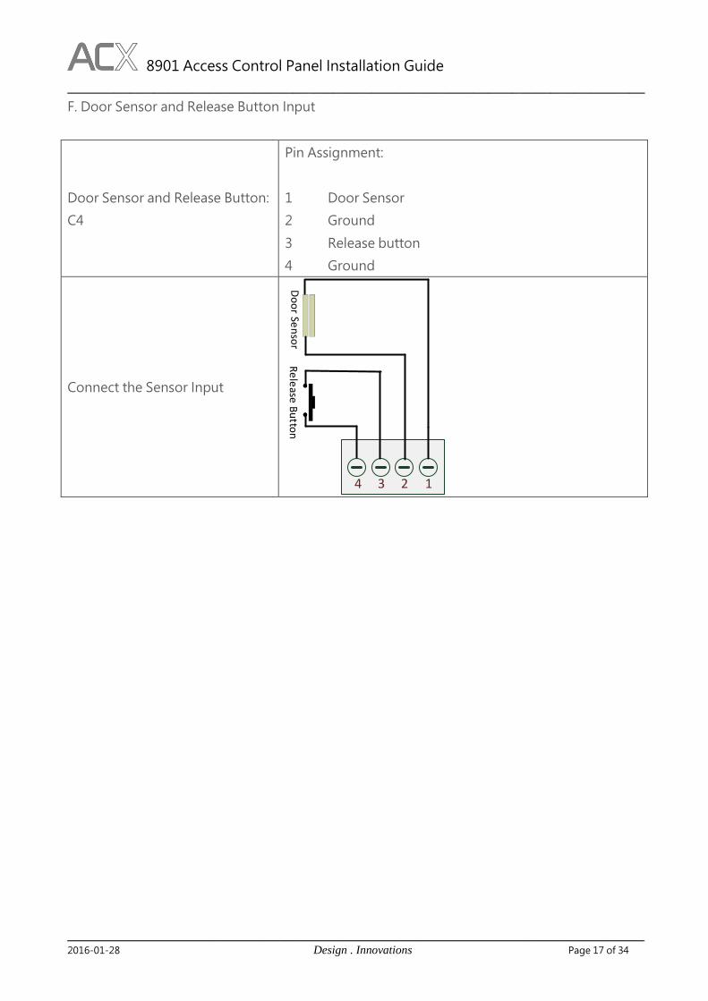
H. Emergency Door Open Device
Emergency Door Open: C7
Pin Assignment:
1 Power Out (12VDC, 100mA)
2 Ground
3 Signal +
4 Signal -
Install the ACX J1 key
switch panel
4 3 2 1
ACX J1
6 5 4 3 2 1
Control PanelS- S+ GND 12V
Pin Type Function Wire Color
1 Red (V-) Red
2 Green (V-) Green
3 VCC (12V) Black
4 Key N.O Amber
5COM
(for Key and Tamper)White
6 Tamper N.O Brown
LED
Pin Assignment for Key Switch
C7 for 8901C10 for 8902
8901 Access Control Panel Installation Guide
__________________________________________________________________________
_______________________________________________________________________________________________________________
2016-01-28 Design . Innovations Page 20 of 34
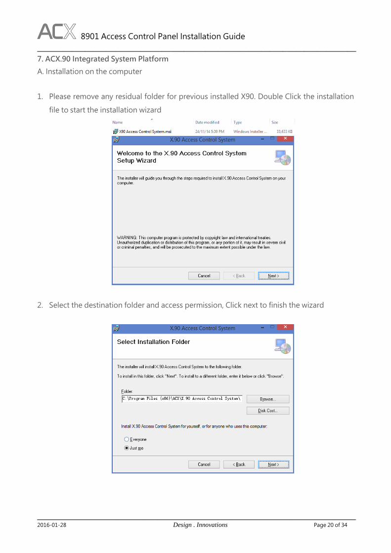
7. ACX.90 Integrated System Platform
A. Installation on the computer
1. Please remove any residual folder for previous installed X90. Double Click the installation
file to start the installation wizard
2. Select the destination folder and access permission, Click next to finish the wizard

8901 Access Control Panel Installation Guide
__________________________________________________________________________
_______________________________________________________________________________________________________________
2016-01-28 Design . Innovations Page 21 of 34
3. Then double click the icon in the desktop
4. Input the database setting. Specify the instance name by using \ after the IP address.
Specify the port by using “ ,” after the IP address.
5. Input the SN and release code

8901 Access Control Panel Installation Guide
__________________________________________________________________________
_______________________________________________________________________________________________________________
2016-01-28 Design . Innovations Page 22 of 34
6. Please make sure install all the patches in the folder of C:\Program Files (x86)\ACX\X.90
Access Control System\Other before proceeding.
B. Set up the communication with control panel
1. Click “Install Panel” icon to add panel to the system
2. Select Access Device for the panel. Add the IP address, port and other information.
8901 Access Control Panel Installation Guide
__________________________________________________________________________
_______________________________________________________________________________________________________________
2016-01-28 Design . Innovations Page 23 of 34
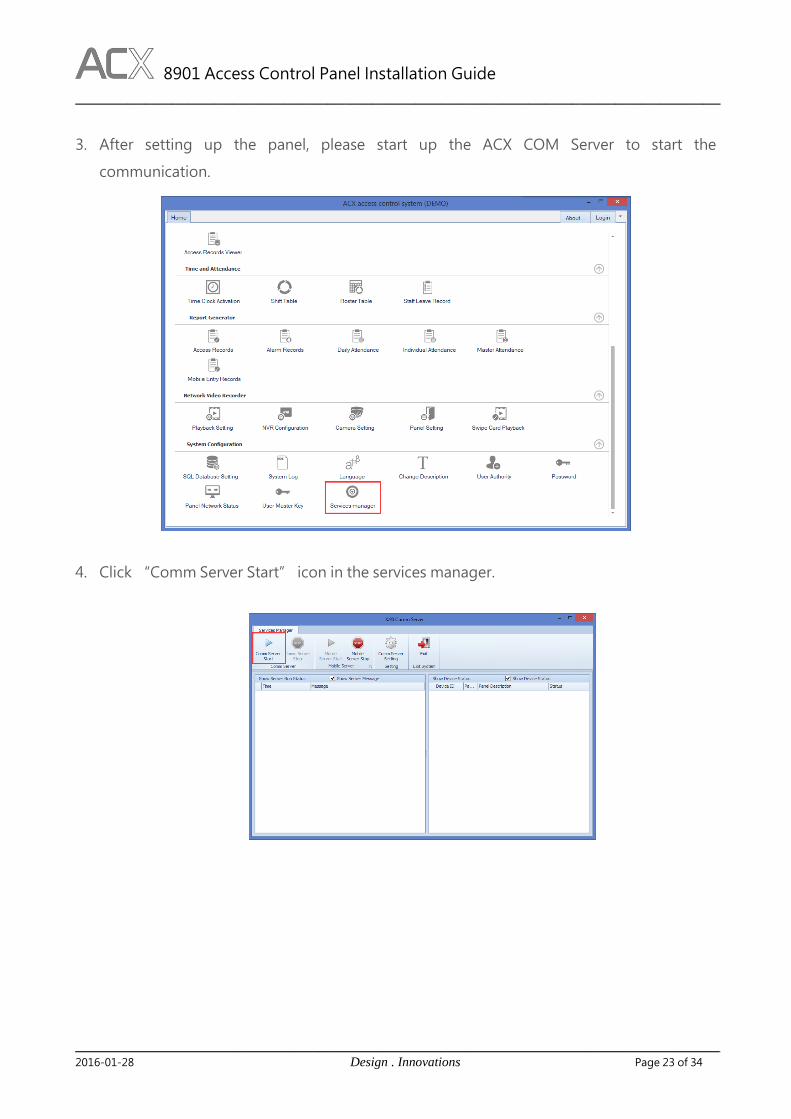
3. After setting up the panel, please start up the ACX COM Server to start the
communication.
4. Click “Comm Server Start” icon in the services manager.

8901 Access Control Panel Installation Guide
__________________________________________________________________________
_______________________________________________________________________________________________________________
2016-01-28 Design . Innovations Page 24 of 34
5. If the communication is successful, you will see a tick in the status box for you control
panel.
6. You can also check the network status in the X.90 software interface.
8901 Access Control Panel Installation Guide
__________________________________________________________________________
_______________________________________________________________________________________________________________
2016-01-28 Design . Innovations Page 25 of 34
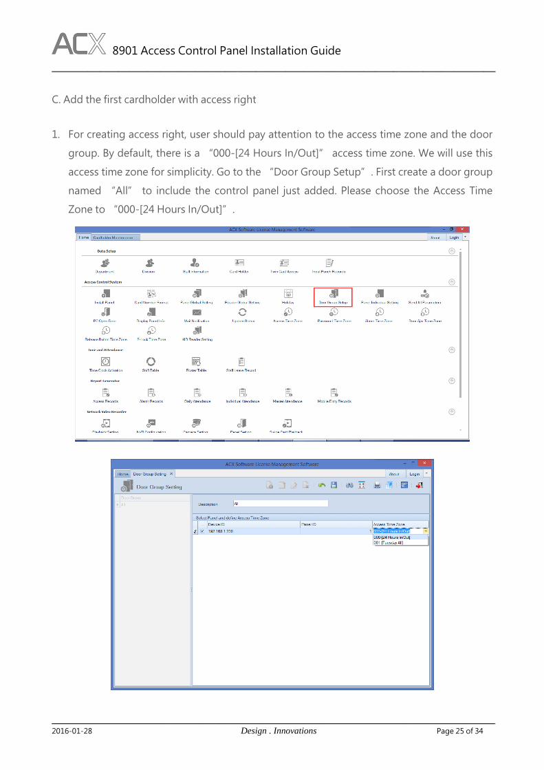
C. Add the first cardholder with access right
1. For creating access right, user should pay attention to the access time zone and the door
group. By default, there is a “000-[24 Hours In/Out]” access time zone. We will use this
access time zone for simplicity. Go to the “Door Group Setup”. First create a door group
named “All” to include the control panel just added. Please choose the Access Time
Zone to “000-[24 Hours In/Out]”.
8901 Access Control Panel Installation Guide
__________________________________________________________________________
_______________________________________________________________________________________________________________
2016-01-28 Design . Innovations Page 26 of 34
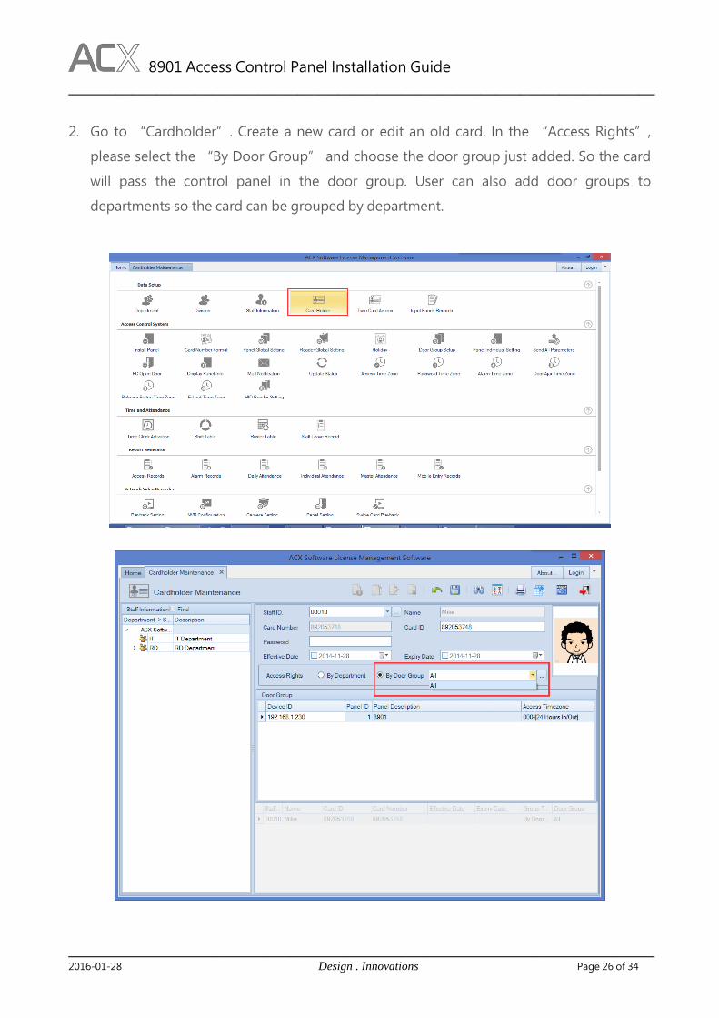
2. Go to “Cardholder”. Create a new card or edit an old card. In the “Access Rights”,
please select the “By Door Group” and choose the door group just added. So the card
will pass the control panel in the door group. User can also add door groups to
departments so the card can be grouped by department.
8901 Access Control Panel Installation Guide
__________________________________________________________________________
_______________________________________________________________________________________________________________
2016-01-28 Design . Innovations Page 27 of 34
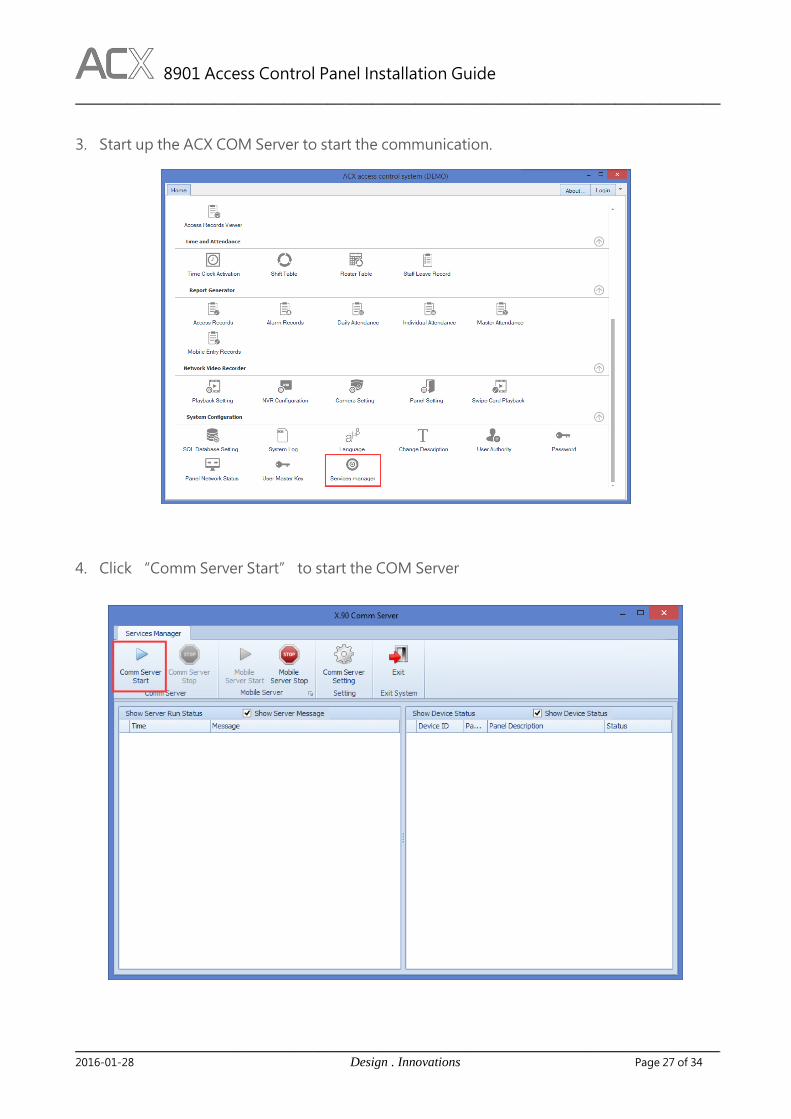
3. Start up the ACX COM Server to start the communication.
4. Click “Comm Server Start” to start the COM Server

8901 Access Control Panel Installation Guide
__________________________________________________________________________
_______________________________________________________________________________________________________________
2016-01-28 Design . Innovations Page 28 of 34
D. Enable Alarms in the control panels
Press the Panel Global Setting icon the main page.
Enable the alarms as the system requires. Press save to make the changes effective.

8901 Access Control Panel Installation Guide
__________________________________________________________________________
_______________________________________________________________________________________________________________
2016-01-28 Design . Innovations Page 29 of 34
Launch the application server for Milestone®
Click the “Milestone” icon in the X90 main page
Launch the application server

8901 Access Control Panel Installation Guide
__________________________________________________________________________
_______________________________________________________________________________________________________________
2016-01-28 Design . Innovations Page 30 of 34
Please put the folder “VideoOS.Matrix.AccessControl.Plugin” into the folder “C:\Program
Files (x86)\Milestone\XProtect Event Server\MIPPlugins”. Restart all Milestone services and
restart Management Application and Smart Client.
Launch the Milestone Management Application, Right click the Acces Control in the menu to
create a new access control server.
Select the “Matrix Access Control System”. Input the right communcation login information.

8901 Access Control Panel Installation Guide
__________________________________________________________________________
_______________________________________________________________________________________________________________
2016-01-28 Design . Innovations Page 31 of 34
Make sure the X90 application server for Milestone is on. Then it will shows the information
retrieved from the X90 system.
Select cameras associated with the doors.

8901 Access Control Panel Installation Guide
__________________________________________________________________________
_______________________________________________________________________________________________________________
2016-01-28 Design . Innovations Page 32 of 34
Press “Next” and there will be a server generated under the Access Control.
Launch the Milestone Smart Client. Press Setup in the Live tab.

8901 Access Control Panel Installation Guide
__________________________________________________________________________
_______________________________________________________________________________________________________________
2016-01-28 Design . Innovations Page 33 of 34
Drag the Access Monitor into the view.
Select the door and the camera for viewing. Be careful about the Events where you can select
which events you want to monitor in the view.
8901 Access Control Panel Installation Guide
__________________________________________________________________________
_______________________________________________________________________________________________________________
2016-01-28 Design . Innovations Page 34 of 34
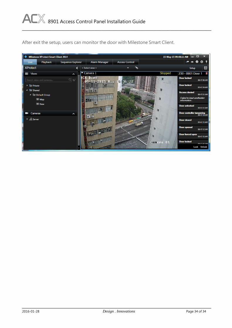
After exit the setup, users can monitor the door with Milestone Smart Client.


![VIOLONCELLO · 2019. 12. 6. · Viola + Violoncello + Doublebass ☆8901 村雲 あや子 (1949-) インタースパーション (1988) [10'30"] [R-8901] MURAKUMO Ayako Interspersion](https://img.dokumen.tips/doc/110x75/60dca7873292620d7378f372/violoncello-2019-12-6-viola-violoncello-doublebass-a8901-e-.jpg)