Embed Size (px)
Citation preview

850 HeaWhe
InsPa
vy Duty el Balancer
truction Manual and rts List
Equipment specifications, options and accessories subject to change without notice

ITALIANO ENGLISH FRANÇAIS
2COD. 653993 Rev.0
AVVERTENZE
Il presente libretto di istruzioni costituisce parte integrante del prodotto. Leggere attentamente leavvertenze e le istruzioni in esso contenute in quanto forniscono importanti indicazioni riguardanti lasicurezza d’ uso e manutenzione.Conservare con cura questo libretto per ogni ulteriore consultazione.
SBM 850 E’ UNA EQUILIBRATRICE CON LANCIO A MOTORE PROGETTATA E COSTRUITAPER EQUILIBRARE LE RUOTE DI AUTOCARRO, AUTOBUS E VETTURA.
LA MACCHINA E’ STATA PREVISTA PER FUNZIONARE ENTRO I LIMITI INDICATI NEL PRESENTELIBRETTO ED IN ACCORDO ALLE ISTRUZIONI DEL COSTRUTTORE.
La macchina dovrà essere destinata solo all’uso per il quale è stata espressamente concepita. Ognialtro uso è da considerarsi improprio e quindi irragionevole.
Il costruttore non può essere considerato responsabile per eventuali danni causati da usiimpropri, erronei ed irragionevoli.
» Evitare di togliere o modificare parti della macchina pregiudicandone l’uso corretto. Per riparazioniconsultare il servizio di assistenza.
» Evitare pulizia con forti getti di aria compressa. Per la pulizia di pannelli o ripiani in plastica utilizzarealcool (EVITARE LIQUIDI CONTENENTI SOLVENTI)
» Prima di avviare il ciclo di equilibratura accertarsi del corretto bloccaggio della ruota sulla flangia
» L’operatore all’equilibratrice non deve indossare abiti con parti svolazzanti; evitare che il personalenon autorizzato si avvicini all’equilibratrice durante il ciclo.
Questo simbolo viene utilizzato nel presente manuale quando si vuole attirare l’attenzionedell’operatore su particolari rischi connessi con l’uso della macchina.
WARNINGS
The present instructions booklet is an integral part of the product. Carefully study the warnings andinstructions contained in it. This information is important for safe use and maintenance.Conserve this booklet carefully for further consultation.
SBM 850 IS A MOTORIZED WHEEL BALANCER DESIGNED AND CONSTRUCTED FOR BAL-ANCING THE WHEELS OF TRUCKS, BUSES, AND CARS.
THE MACHINE HAS BEEN DESIGNED TO OPERATE WITHIN THE LIMITS DESCRIBED IN THISBOOKLET AND IN ACCORDANCE WITH THE MAKER’S INSTRUCTIONS.
The machine must be used only for the purpose for which it was expressly designed. Any other use isconsidered wrong and therefore unacceptable.
The maker cannot be held responsible for eventual damage caused by improper, erroneous, orunacceptable use.
» Do not remove or modify parts of the machine. This could compromise its correct use. For repairscontact the assistance service.
» Do not clean with powerful compressed air jets. For the cleaning of panels or plastic surfaces usealcohol (DO NOT USE LIQUIDS CONTAINING SOLVENTS).
» Before starting a balancing cycle, check that the wheel is correctly fixed to the adapter.
» The machine operator must not wear loose, dangling garments. Do not allow unauthorized person-nel to approach the machine during an operating cycle.
This symbol is used in the present manual to warn the operator of particular risks associated withthe use of the machine.
AVERTISSEMENTS
Ce manuel d’instructions fait partie intégrante du produit. Lire attentivement les avertissements etles instructions données car elles fournissent d’importantes indications concernant la sécuritéd’emploi et d’entretien.Conserver avec soin pour toute consultation.
SBM 850 EST UNE EQUILIBREUSE A LANCEMENT MOTORISE PROJETEE ET FABRIQUEEPOUR EQUILIBRER LES ROUES DE CAMION, D’AUTOBUS ET DE VOITURE.
L’APPAREIL A ÉTÉ PRÉVU POUR FONCTIONNER DANS LES LIMITES INDIQUÉES DANS CEMANUEL ET SELON LES INSTRUCTIONS DU CONSTRUCTEUR.
L’appareil ne devra être destiné qu’à l’emploi pour lequel il a été proprement conçu. Tout autre emploidoit être considéré abusif et donc inadmissible.
Le constructeur ne pourra être considéré responsable des éventuels dommages causés à lasuite d’emplois abusifs, fautifs et inadmissibles.
» Eviter d’ôter ou de modifier des parties de la machine en préjugeant son utilisation correcte. Pourles réparations, consulter le service après-vente.
» Eviter le nettoyage avec des jets d’air comprimé puissants. Le nettoyage des panneaux ou desétagères en plastique doit être fait en utilisant de l’alcool. (EVITER DES LIQUIDES CONTENANTDES SOLVANTS)
» Avant de mettre en marche le cycle d’équilibrage s’assurer du blocage correct de la roue sur leplateau
» L’opérateur de l’équilibreuse ne doit pas porter de vêtements flottants; éviter que le personnel nonautorisé s’approche de l’équilibreuse pendant le cycle.
Ce symbole est utilisé dans ce manuel pour attirer l’attention de l’opérateur sur des risquesparticuliers dérivant de l’utilisation de la machine.

ITALIANO ENGLISH FRANÇAIS
4COD. 653993 Rev.0
INDICE
AVVERTENZE ................................................................................................................................ 2
LEGENDA delle PRINCIPALI PARTI COMPONENTI .................................................................. 6
CARATTERISTICHE TECNICHE .................................................................................................. 6
ACCESSORI IN DOTAZIONE e ACCESSORI A RICHIESTA .................................................... 10
DISIMBALLO e COLLOCAMENTO ............................................................................................ 12
INSTALLAZIONE- Montaggio carter di protezione ................................................................................................... 14- Collegamento pneumatico .......................................................................................................... 14- Collegamento elettrico ................................................................................................................ 14
INSTALLAZIONE FLANGE- Montaggio flange ........................................................................................................................ 16- Serraggio ruote ........................................................................................................................... 16
INSTALLAZIONE ALTRE FLANGE ............................................................................................ 18
MALFUNZIONAMENTI, LORO CAUSE E POSSIBILI RIMEDI ................................................. 20
ISTRUZIONI PER L’USO- Pannello comandi (legenda) ....................................................................................................... 26
EQUILIBRATURA RUOTE- Selezione tipo di ruota ................................................................................................................ 28- Selezione programma di equilibratura ........................................................................................ 28- Impostazione dati ruota .............................................................................................................. 30- Programmazione e fissaggio pesi adesivi con calibro speciale ................................................. 30- Programma di separazione dei pesi ........................................................................................... 32- Programmazione equilibratura ruote motociclo .......................................................................... 32- Ottimizzazione Squilibrio ............................................................................................................ 34
CONFIGURAZIONE EQUILIBRATRICE .................................................................................... 36
TARATURA BASE DELLA MACCHINA ..................................................................................... 38
CONTROLLO EQUILIBRATURA .............................................................................................. 40
AUTODIAGNOSI .......................................................................................................................... 42
MANUTENZIONE ORDINARIA ................................................................................................... 44
TRASPORTO E MOVIMENTAZIONE .......................................................................................... 44
ACCANTONAMENTO E ROTTAMAZIONE ................................................................................ 44
ASSISTENZA TECNICA E PARTI DI RICAMBIO ...................................................................... 46- Schemi elettrici- Tavole esplosi
CONTENTS
WARNINGS .................................................................................................................................... 2
TABLE OF MAIN COMPONENT PARTS ...................................................................................... 6
TECHNICAL CHARACTERISTICS ............................................................................................... 6
ACCESSORIES SUPPLIED AND ON REQUEST ...................................................................... 10
UNPACKING AND LOCATION .................................................................................................... 12
INSTALLATION- Fitting safety guards ................................................................................................................... 14- Pneumatic connection ................................................................................................................ 14- Electrical connection .................................................................................................................. 14
FITTING THE ADAPTER- Fitting the adapter ....................................................................................................................... 16- Fixing the wheel .......................................................................................................................... 16
FITTING OTHER ADAPTERS .................................................................................................... 18
TROUBLESHOOTING ................................................................................................................. 21
INSTRUCTIONS FOR USE- Control panel (table) ................................................................................................................... 26
WHEEL BALANCING- Selecting wheel type ................................................................................................................... 28- Selecting balancing program ...................................................................................................... 28- Setting wheel dimensions ........................................................................................................... 30- Programming and fitting adhesive weights with the special gauge ............................................ 30- Weight separation program ........................................................................................................ 32- Programming motorbike wheel balancing .................................................................................. 32- Optimizing imbalance ................................................................................................................. 34
CONFIGURING THE WHEEL BALANCER ............................................................................... 36
BASIC MACHINE CALIBRATION ............................................................................................... 38
CHECKING THE BALANCING OPERATION ............................................................................. 40
AUTO-DIAGNOSIS ...................................................................................................................... 42
ROUTINE MAINTENANCE .......................................................................................................... 44
MOVING AND TRANSPORTING ................................................................................................ 44
STORAGE AND SCRAPPING ..................................................................................................... 44
TECHNICAL ASSISTANCE AND SPARE PARTS ..................................................................... 46- Electrical circuit diagrams- Exploded diagrams
INDEX
AVERTISSEMENTS ....................................................................................................................... 2
LEGENDA des PRINCIPAUX COMPOSANTS ............................................................................. 7
CARACTERISTIQUES TECHNIQUES ......................................................................................... 7
ACCESSOIRES EN DOTATION et ACCESSOIRES SUR DEMANDE ...................................... 11
DEBALLAGE ET BRANCHEMENT ............................................................................................ 13
INSTALLATION- Montage du carter de protection ................................................................................................. 15- Connection pneumatique ............................................................................................................ 15- Branchement .............................................................................................................................. 15
INSTALLATION DES PLATEAUX- Montage des plateaux ................................................................................................................ 17- Serrage des roues ...................................................................................................................... 17
INSTALLATION DES AUTRES PLATEAUX ............................................................................. 19
ANOMALIES, LEURS CAUSES ET REMEDES POSSIBLES ................................................... 22
INSTRUCTIONS D’UTILISATION- Panneau des commandes (légenda) .......................................................................................... 27
EQUILIBRAGE DES ROUES- Sélection du type de roue ........................................................................................................... 28- Sélection du programme d’équilibrage ....................................................................................... 28- Introduction des données de la roue .......................................................................................... 31- Programmation et fixage des masses avec calibre spécial ....................................................... 31- Programme de séparation des masses ...................................................................................... 33- Programmation d’équilibrage des roues de moto ....................................................................... 33- Optimisation du balourd .............................................................................................................. 34
CONFIGURATION DE L’EQUILIBREUSE ................................................................................ 36
TARAGE DE LA MACHINE ......................................................................................................... 38
CONTROLE DE L’EQUILIBRAGE ............................................................................................ 40
AUTODIAGNOSTIC .................................................................................................................... 42
ENTRETIEN COURANT ............................................................................................................. 45
TRANSPORT ET MANUTENTION ............................................................................................ 45
MISE DE COTE ET DEMOLITION ............................................................................................ 45
ASSISTANCE TECHNIQUE ET PIECES DETACHEES ........................................................... 46- Schémas électriques- Vues éclatées

ITALIANO ENGLISH SBM 850
6COD. 653993 Rev.0
DISEGNO ILLUSTRATIVO DELLA MACCHINA
LEGENDAA: Interruttore generaleB: Cavo di alimentazioneC: Cruscotto portapesiD: Pannello comandiE: Asta di misurazioneF: Carter Protezione RuotaG: AlberoH: FlangiaL: Carrello sollevatoreM: SollevatoreN: Protezione anti-cesoiamentoP: Pedali comando sollevatoreQ: Supporto Flangia ed accessoriR: Gruppo filtro FR + L. Alimentazione pneumatica
CARATTERISTICHE TECNICHE
SBM 850 è un’equilibratrice elettronica per ruote di autocarro e autovetturaa lancio unico e ciclo completamente automatico: avviamento, misura e
frenata.» La macchina è in grado di equilibrare con precisione ruote di autocarro,
autobus e autovettura di peso fino a 160 kg.» Lettura digitale dello squilibrio su doppio display di grandi dimensioni per
una visualizzazione chiara ed efficace.» L’impostazione tramite tastiera numerica delle tre misure della ruota
permette un utilizzo semplice e rapido della macchina.» Centraggio automatico della ruota grazie al nuovo sollevatore pneumatico,
parte integrante della macchina.» Un sistema di autodiagnosi ed autotaratura rende di estrema semplicità
la manutenzione.» Il funzionamento è a lancio unico e a ciclo automatico: l’avviamento
avviene tramite l’abbassamento del carter di protezione o la pressionedel pulsante START; anche la frenata avviene automaticamente, al terminedel ciclo di misura.
» La macchina misura contemporaneamente lo squilibrio dinamico dellaruota con memorizzazione del peso e della posizione; la macchina è inoltreprovvista di 5 programmi ALU (2 per autocarro) con l’opzione diseparazione dei pesi, programma di equilibratura statica ed ottimizzazione
statica.
» Per garantire la sicurezza dell’operatore l’equilibratura delle ruote pesantida autocarro avviene a bassa velocità di rotazione (100giri/min).
» Per assicurare la massima sicurezza la macchina è inoltre dotata delcarter di protezione ruota che viene installato di serie per proteggerel’operatore da eventuale fango e/o acqua e dall’eventuale eiezione diparti del pneumatico o del cerchio.
» Il carter di protezione permette l’introduzione di ruote aventi un diametroesterno max di 1200 mm; quando il carter copertura ruota è aperto, undispositivo elettromeccanico non permette l’avviamento della macchina.
» L’equilibratrice SBM 850 è inoltre dotata di sollevatore pneumatico peragevolare le operazioni di montaggio della ruota sulla macchinaequilibratrice e di centraggio e bloccaggio della ruota sulla flangia: conquesto sollevatore la ruota è sempre al centro, grazie al sistemaautomatico di centraggio orizzontale ed alla regolazione verticale.
» Il sollevatore può essere utilizzato per sollevare ruote di autocarro chehanno un peso di 160 kg ma e’ anche in grado di portare sull’albero diequilibratura ruote fino a una dimensione di circa 15 pollici.
» Il sollevatore è dotato di una pedaliera dalla duplice funzione: agevolala movimentazione della ruota; protegge l’operatore in caso di cadutadella ruota; dispone inoltre di un disposit ivo di sicurezzaanticesoiamento.
ILLUSTRATIVE MACHINE DRAWING
KEYA: Main switchB: Electrical power cableC: Weight holder dashboardD: Control panelE: Measuring rodF: Wheel cover guardG: ShaftH: AdapterL: Lift trolleyM: LifterN: Anti-shearing guardP: Lifter control pedalsQ: Adapter and accessories holderR: FR + L filter group. Pneumatic supply
TECHNICAL CHARACTERISTICS
The SBM 850 is an electronic wheel balancing machine for truck and carwheels. It operates with a single fully automatic cycle which includes: start
up, measuring and braking.» The machine offers precision balancing of truck, bus, and car wheels of
up to 200 kg.» Imbalance is displayed digitally on a large double screen for clear and
efficient reading.» The three wheel measurements are entered on the number pad for quick
and easy operation.» Wheels are centered automatically by the new pneumatic lifter integrated
into the machine.» A system of self-diagnosis and automatic calibration ensures easy main-
tenance.» Operation is with a single fully automatic cycle. Start up by lowering the
guard and pressing the START button. After measuring the machinebrakes automatically.
» The machine measures the dynamic imbalance points simultaneouslyand memorizes the weights and positions. It also has 5 ALU programs (2
for trucks) with the option of separating the weights, a static balancing
program, and static optimization.
» To guarantee the safety of operators the balancing of heavy truck wheelsis performed at a low rotation speed (100 r.p.m.).
» For maximum safety the machine also has a wheel cover guard fitted asstandard to protect operators from mud, water or the ejection of parts ofthe tire or rim.
» The safety cover allows the insertion of wheels up to a max. of 1200 mm.When the guard is open an electromechanical device prevents the ma-chine from starting up.
» The SBM 850 is also equipped with a pneumatic lifter to simplifymounting of wheels, centering, and fixing on the machine adapter.The lifter has an automatic system for horizontal centering and verticaladjustment to ensure that wheels are always centered.
» The lifter can raise truck wheels of up to 160 kg in weight and alsohandle wheels with a diameter down to 15 inches.
» The lifter has a double function pedal. It helps to move the wheel andprotects operators from the danger of falling wheels. It also has an anti-shearing safety device.
1

ITALIANO ENGLISH SBM 850
8COD. 653993 Rev.0
DATI TECNICI
DIMENSIONIAltezza max (protezione ruota aperta) .................................... 1950 mmProfondità max (protezione ruota chiusa) ............................... 1350 mmLarghezza max (con carrello sollevatore) ............................... 2000 mm
PESOPeso Netto (con carter) ............................................................... 248 kgPeso Lordo (con imballo) ............................................................ 362 kg
ALIMENTAZIONE ELETTRICAPotenza assorbita ....................................................................... 1.0 kWFasi ................................................................................................... 1 ~Tensione d’alimentazione ...................... 230V - 50/60Hz (115V - 60Hz)Grado di protezione ....................................................................... IP 22Velocità d’equilibratura (ruote autovettura) ................ 167 g/min a 50Hz................................................................................... 200 g/min a 60Hz
Velocità d’equilibratura (ruote autocarro) ............................. ~100 g/min.......................................................................................... min 42 g/min
Risoluzione lettura squilibrio (autovettura) ..... 1/5 g (0.05/0.25once)Risoluzione lettura squilibrio (autocarro) ........ 10/50 g (0.5/1.0once)Rumorosità ............................................................................... < 75 db
SOLLEVATOREAlimentazione pneumatica .............................. 800-1200 kPa (8-12 bar)Portata max .................................................................................. 160kgAltezza max di sollevamento ruota ........................................... 440 mm
GAMMA DI APPLICAZIONI
Larghezza cerchione (min/max) .................................................. 1"- 20"Diametro cerchione (min/max) .............................................. 10” - 26.5”Diametro ruota (max) .............................................................. 1200 mmLarghezza ruota (max) ....................................................... 650/800 mmPeso ruota (max) ......................................................................... 160 kg
Nota Bene: le misure minime e massime sopra elencate si riferiscono allosquilibrio dinamico nei due piani di compensazione o al solo squilibrio statico.Lo squilibrio viene indicato con 3 cifre digitali. L’indicazione può essere ingrammi o in once (la trasformazione viene effettuata tramite la tastiera diprogrammazione).La posizione angolare dello squilibrio viene indicata dai diodi luminosi.
DATI DI TARGA
REGISTRATION PLATE DATA
DONNEES DE PLAQUE
ANGABEN AUF DEM MATRIKELSCHILD
DATOS DE CHAPA
ÄÀÍÍÛÅ ÒÀÁËÈ÷ÊÈ
TECHNICAL DATA
DIMENSIONSMax. height (wheel cover open) ............................................. 1950 mmMax. depth (wheel cover closed) ............................................ 1350 mmMax. width (with lift trolley) ..................................................... 2000 mm
WEIGHTNet weight (with guard) ............................................................... 248 kgGross weight (with packing) ........................................................ 362 kg
ELECTRICAL SUPPLYAbsorbed power .......................................................................... 1.0 kWPhases .............................................................................................. 1 ~Supply voltage ....................................... 230V - 50/60Hz (115V - 60Hz)Protection grade ............................................................................. IP 22Balancing speed (car wheels) .................................. 167 r.p.m. at 50Hz................................................................................. 200 r.p.m. at 60Hz
Balancing speed (truck wheels) ........................................... ~100 r.p.m........................................................................................... min 42 r.p.m.
Imbalance reading resolution (car) ................ 1/5 g (0.05/0.25ounce)Imbalance reading resolution (truck) ............. 10/50 g (0.5/1.0ounce)Noise level ............................................................................... < 75 db
LIFTERPneumatic supply ............................................ 800-1200 kPa (8-12 bar)Max. load .................................................................................... 160 kgMax. wheel lifting height ........................................................... 440 mm
RANGE OF APPLICATIONS
Rim width (min./max.) ................................................................. 1"- 20"Rim diameter (min./max.) ...................................................... 10” - 26.5”Wheel diameter (max.) ............................................................ 1200 mmWheel width (max.) ............................................................ 650/800 mmWheel weight (max.) ................................................................... 160 kg
N.B.: the maximum and minimum measurements listed above refer to dy-namic imbalance on the two compensation planes or to a single static imbal-ance.Imbalance is given in 3 figures. The reading can be in grams or ounces (thisis changed using the programming keyboard).The angular position of the imbalance is indicated by LED’s.

ITALIANO ENGLISH SBM 850
10COD. 653993 Rev.0
2
3
1
F
B
A
2
5
4
3
ACCESSORI IN DOTAZIONE (Fig.2)
LEGENDAA. Pinza contrappesiB. Calibro misurazione larghezza cerchioC. Gruppo flangia per ruote autocarroD. Coni di centraggio specialiE. Coni di centraggio per ruote autovetturaF. Calibro posiziona pesi speciale per cerchi in alluminio
ACCESSORI A RICHIESTA (Fig.3)
LEGENDA1. Flangia 3/4/5 Fori con Dadi Standard2. Dadi Rapidi3. Flangia per Ruote Moto4. Distanziale5. Anello Centraggio Renault - Citroen - Peugeot
ACCESSORIES PROVIDED (Fig.2)
KEYA. Counterweight pliersB. Rim width measuring gaugeC. Adapter group for truck wheelsD. Special centering conesE. Centering cones for car wheelsF. Special weight positioning gauge for aluminum wheels
ACCESSORIES ON REQUEST (Fig.3)
KEY1. 3/4/5 Hole adapter with standard nuts2. Quick release nuts3. Motorcycle wheel adapter4. Spacer5. Centring rings for Renault - Citroën - Peugeot
E
D
C

ITALIANO ENGLISH SBM 850
12COD. 653993 Rev.0
4
DISIMBALLO
» Dopo avere tolto l’imballaggio (ved. fig.4) assicurarsi del’integrità dellamacchina controllando che non vi siano parti visibilmente danneggiate.In caso di dubbio non utilizzare la macchina e rivolgersi a personaleprofessionalmente qualificato e/o al proprio rivenditore.
» Gli elementi dell’imballaggio (sacchetti di plastica, pluriball, polietilene,chiodi, graffette, legni ecc.) non devono essere lasciati alla portata deibambini in quanto potenziali fonti di pericolo.Riporre i suddetti materiali negli appositi luoghi di raccolta se inquinantio non biodegradabili.
» La scatola contenente gli accessori in dotazione è inserita nell’imballodella macchina.
COLLOCAMENTO
» L’equilibratrice deve essere posta su un solido pavimento di cemento osimile.Un vuoto sottostante può dare luogo ad imprecisione nelle misure deglisquilibri.
» DIMENSIONI D’INGOMBRO:2000 mm x 1350 mm x h 1950mm
» DISTANZE DI SICUREZZA: Per un utilizzo sicuro ed ergonomico della macchina è consigliabile
collocarla ad una distanza minima di 500mm dalle pareti circostanti (fig.5).
» PRESCRIZIONI DI FISSAGGIO:Il basamento della macchina è provvisto di 3 fori per il fissaggio alpavimento. Un buon fissaggio è indispensabile per avere indicazioniprecise e costanti.
5
UNPACKING
» After removing the packing (strapping, seals, cardboard, and the pallet,see fig. 4) check the machine for missing or damaged parts. If in doubt
do not use the machine and refer to professionally qualified personneland/or to the seller.
» The packing materials (plastic bags, pluriball, polythene, nails, staples,timber, etc.) must not be left within reach of children since these arepotentially dangerous.Deposit the above mentioned materials at the relevant collection points ifthey are pollutants or are non biodegradable.
» The box containing the accessories provided is contained in the pack-ing of the machine.
LOCATION
» The wheel balancer must be located on a solid floor in concrete or similarmaterial. An underlying cavity could cause imprecise imbalance read-ings.
» OVERALL DIMENSIONS:2000 mm x 1350 mm x h 1950mm
» SAFE DISTANCE:For the safe and ergonomic use of the machine it is advisable to locate ita minimum of 500 mm from the surrounding walls (fig. 5).
» FIXING INSTRUCTIONS:The machine base has 3 holes for fixing to the floor. This is essential toensure accurate and consistent readings.

ITALIANO ENGLISH SBM 850
14COD. 653993 Rev.0
6 7
INSTALLAZIONE
Operazioni di collegamento e verifiche di funzionamento
MONTAGGIO CARTER PROTEZIONEVedere fig. 6 e procedere come segue:1. inserire il carter protezione ruota nel perno di supporto in corrispondenza
del foro;2. regolare l’inclinazione del carter: la parte anteriore del carter di protezione
deve trovarsi ad un’altezza di circa 1900mm da terra quando il carter èaperto (fig.5);
3. stringere la vite di bloccaggio;4. chiudendo il carter la parte anteriore deve trovarsi ad un’altezza di circa
1000mm da terra (fig.5).
COLLEGAMENTO PNEUMATICOCollegare la presa aria al raccordo posto sul gruppo filtro (fig.7).
COLLEGAMENTO ELETTRICO
OGNI INTERVENTO SULL’IMPIANTO ELETTRICO, ANCHE DILIEVE ENTITÀ, DEVE ESSERE EFFETTUATO DA PERSONALEPROFESSIONALMENTE QUALIFICATO !
» Controllare la conformità tra la tensione di linea e quella indicata sullatarga della macchina.
» Collegare il cavo dell’alimentazione a una spina conforme alle normeEuropee o alle norme del paese di destinazione della macchina. La spinadeve essere provvista obbligatoriamente del contatto di terra.
» Verificare l’efficacia della messa a terra.» La macchina deve essere allacciata alla rete tramite un sezionatore
onnipolare conforme alle norme Europee, con apertura dei contatti dialmeno 3mm.
» Effettuato il collegamento, e con la macchina inserita, la ruota montatadeve ruotare in senso orario, vista dal lato destro della macchina(fig.8a). La corretta direzione di rotazione è indicata da una freccia sulla
carcassa della macchina.
» Se la rotazione avviene nel senso sbagliato, la macchina funzionerà solofintanto che il tasto di avvio rimane premuto (il display visualizza E03).
» Nel caso in cui si verificasse un uso anormale della macchina, azionareimmediatamente l’interruttore generale e controllare il manuale diistruzioni nella sezione ricerca guasti.
IL COSTRUTTORE DECLINA OGNI RESPONSABILITÀ PER LAMANCATA OSSERVANZA DI DETTE PRESCRIZIONI.
Prestare sempre particolare attenzione ai SEGNALI DI SICUREZZArappresentati da appositi adesivi applicati sulla macchina.
Fig.8b: etichetta scarica elettrica - cod. N.100789Nel caso di smarrimento o deterioramento dell’etichetta adesiva si prega dirichiederla attraverso il relativo numero di codice, al servizio “parti di ricambio”SICAM.
8a
8b
INSTALLATION
Connection procedures and operating checks
FITTING THE GUARD COVERSee fig. 6 and proceed as follows:1. Insert the hole in the wheel cover onto the support pin.2. Adjust the inclination of the cover. The forward part of the guard cover
must be at a height of about 1900 mm from the ground when the cover isopen.
3. Tighten the fixing screws.4. When closed the forward part of the cover should be at a height of about
1000 mm from the ground (see fig. 5).
PNEUMATIC CONNECTIONConnect the air line to the connector on the filter grou (fig.7).
ELECTRICAL CONNECTION
ALL WORK ON THE ELECTRICAL SYSTEM, EVEN OF A MINORNATURE, MUST BE CONDUCTED BY PROFESSIONALLY QUALI-FIED PERSONNEL !
» Check that the supply voltage is the same as that indicated on the ma-chine identification plate.
» Connect the electrical power cable to a plug that conforms with Euro-pean standards or the standards of the country in which the machine isused. The plug must have a ground/earth connection.
» Check the effectiveness of the ground/earth connection.» The machine must be connected to the supply through a multi-pole cut-
off switch in conformity with European standards and with contact open-ing gap of at least 3 mm.
» When connected and switched on, mounted wheels must rotate in a clock-wise direction as seen from the right-hand side of the machine(fig.8a).The correct direction of rotation is indicated with an arrow on the
machine body.» If the direction of rotation is wrong the machine will operate only while
the start button is pressed down (the display reads E03).» If the machine functions abnormally immediately switch off the main
switch and check the troubleshooting section of the instructions manual.
THE MANUFACTURER DECLINES ALL RESPONSIBILITY FOR THEFAILURE TO OBSERVE THE INSTRUCTIONS GIVEN ABOVE.
Always pay attention to the SAFETY WARNING SIGNS applied aslabels on the machine.
Fig. 8b: electrical discharge label – code no. 100789In the case of the disappearance or deterioration of the adhesive labels please
request replacements from SICAM’s spare parts service, quoting the rel-
evant code number.

ITALIANO ENGLISH SBM 850
16COD. 653993 Rev.0
INSTALLAZIONE FLANGE
MONTAGGIO FLANGEPrima di fissare le flange alla macchina è opportuno pulire il cono dell’alberomacchina, la zona di centraggio sull’albero ed il foro della flangia stessa; uncattivo adattamento della flangia influirà sulla precisione dell’equilibratura.La macchina può funzionare sia con le flange per autocarro che con quelleper autovetture; per le flange autocarri montare sul mandrino l’appositoraccordo di centraggio.Le illustrazioni mostrano il sistema dei fissaggio delle flange.
» La fig.9a mostra il sistema di fissaggio del corpo flangia (flangia aconi per autovetture).
» La fig.9b mostra il sistema di fissaggio del raccordo di centraggio(distanziale per flangia autocarri).
» La fig.9c mostra il sistema di fissaggio dell’adattatore per ruote diautocarri.
SERRAGGIO RUOTE
» SERRAGGIO RUOTA AUTOCARROLe figure 10a e 10b mostrano il sistema di serraggio ruota d’autocarroutilizzando il relativo adattatore: la ruota viene montata sull’adattatore ebloccata dalla croce di centraggio.Bloccare la ruota con cura: un centraggio non perfetto provocainevitabilmente degli squilibri.
» SERRAGGIO RUOTA AUTOMOBILELe figure 11a e 11b mostrano il sistema di serraggio ruota d’automobileutilizzando la flangia a coni.
9a
10a
9c
FITTING THE ADAPTER
FITTING THE ADAPTERBefore fitting the adapter to the machine it is advisable to clean the machineshaft cone, the shaft centering area, and the hole in the adapter. A badlyfitted adapter will compromise the accuracy of balancing.The machine can operate with either the truck or car adapter. When usingthe truck adapter fit the special centering connector on the spindle.
» Fig. 9a shows the fixing method for the adapter unit (cone adapter forcar wheels).
» Fig. 9b shows the fixing method for the centering connector (spacerfor truck wheel adapter).
» Fig. 9c shows the fixing method for the truck wheel adapter.
FIXING THE WHEEL
» FIXING TRUCK WHEELSFigures 10a and 10b illustrate the fixing method for truck wheels usingthe appropriate adapter. The wheels are mounted on the adapter andfixed in place with the centering cross.Take care when fixing the wheel since imperfect centering will inevitablecreate imbalance.
» FIXING CAR WHEELSFigures 11a and 11b illustrate the fixing method for car wheels usingthe cone adapter.
9b
11b
11a
10b

ITALIANO ENGLISH SBM 850
18COD. 653993 Rev.0
15
1312
14
INSTALLAZIONE ALTRE FLANGE
MONTAGGIO FLANGIA UNIVERSALE 3/4/5 FORIPrima di fissare le flange alla macchina è opportuno pulire il cono dell’alberomacchina ed il foro della flangia stessa.Un cattivo adattamento della flangia influirà sulla precisione dell’equilibratura.
» La fig.12 mostra il sistema di fissaggio della flangia universale 3/4/5fori.
» Le fig.15 mostra il sistema di serraggio ruota d’automobile utilizzando laflangia universale 3/4/5 fori.
MONTAGGIO FLANGIA MOTO
» La fig.14 mostra il sistema di fissaggio della flangia motociclo.
» La fig.15 mostra il sistema di serraggio della ruota motociclo utilizzandola flangia moto.
FITTING OTHER ADAPTERS
FITTING THE UNIVERSAL ADAPTER 3/4/5 HOLES
Before fitting the adapter to the machine it is advisable to clean the machineshaft cone and the adapter hole.A badly fitted adapter will compromise the accuracy of balancing.
» Fig. 12 illustrates the fitting method for the 3/4/5 hole universal adapter.
» Fig. 15 illustrates the fixing method for car wheels using the 3/4/5 holeuniversal adapter.
FITTING THE MOTORBIKE WHEEL ADAPTER
» Fig. 14 illustrates the fitting method for the motorbike wheel adapter.
» Fig. 15 illustrates the fixing method for motorbike wheels using the mo-torbike adapter.

21COD. 653993 Rev.0
ENGLISHTROUBLESHOOTING
During the operation of the machine various malfunctions are possible. If these are registered by the microprocessor they are indicated on the display with an “E” followed by a number, with the following meanings.
Any other faults are largely technical in nature and must be checked and resolved by PROFESSIONALLY QUALIFIED PERSONNEL.
display malfunctioning Causes Trouble-shooting
Displays do not come on
The card is not powered up. 1. External supply off or phase not working. 2. Fuse blown in the electrical plant. 3. Control panel fuse blown.
1. Check that positive/negative and neutral are connected up to balancer. 2. Replace fuses in electrical plant (blown fuses indicate fault in electric plant) 3. Replace fuses on control panel (blown fuses indicate fault in electronic part).
Err 1 Err 1 appears on power-up 1. The card has lost the calibration data and factory configuration setting. 2. One or more calibration or setting phases have not been carried out.
1. Repeat all calibration and balancer configuration stages 2. Perform missing programming or setting operations.
Err 2 During the measuring cycle the Err 2 message appears. 1. The guard has been raised before completion of measurements. 1. Wait for end of measuring launch before raising guard. Err 3 During the measuring cycle the Err 3 message appears. 1. On start-up (using START key or lowering guard) the wheel was rotating backwards
2. Motor winding inverted.
1. Ascertain that the wheel is still before start-up and in any case avoid rotating wheel backwards on START.
2. Check for correct motor connection. Err 4 The motor does not turn (with START pressed) or after about 20 sec. the Err 4
message appears.
1. The motor cannot reach the revolutions needed for effective balancing 2. electronic card malfunctioning 3. electrical plant malfunctioning
1. Check mains voltage (it is probably low) 2. Replace electronic card 3. Replace electrical part
Err 5 At end of second calibrating run with the wheel Err 5 appears on the display. 1. Calibration weight has not been applied on the wheel. 2. The pick-ups have not been connected
1. Repeat calibration from beginning and apply the calibration weight when instructed in the calibration procedure (also see “Basic Machine Calibration”)
2. Check pick-up connections. Err 6 Message Err 6 appears when pressing the START key.
1. The guard has not been lowered. 2. Guard microswitch broken
1. Lower guard with wheel mounted. 2. Replace microswitch.
Err 7 At end of second calibrating run with the wheel Err 7 appears on the display
1. Phase difference between the 2 pick-ups is too large.
1. a) check that the calibration weight has been correctly applied; b) also check machine location; it is probably not stable and is vibrating excessively; c) if the problem persists after having stabilised the machine correctly, check the sensor and electronic card connections (and replace if necessary); d) replace pick-ups; e) if after replacing pick-ups the problem is not solved, replace the card.
Err 8 At end of second calibrating run with the wheel Err 8 appears on the display 1. The left pick-up has not been correctly connected or is defective or the cable is disconnected. 1. Check left pick-up connection (and replace if necessary). Err 9 At end of second calibrating run with the wheel Err 9 appears on the display 1. The right pick-up has not been correctly connected or is defective or the cable is disconnected. 1. Check right pick-up connection (and replace if necessary).
Err 10
During launch Err 10 appears on the display. 1. Position sensors in optoelectronics defective. 2. The motor will not turn
1. a) check optoelectronic card connection. b) check the optoelectronic card is protected from daylight and cover if necessary; c) if the defect persists check and if necessary replace the optoelectronic card.
2. Check electrical part. Err 11
During launch Err 11 appears on the display.
1. Passage through zero sensor defective in optoelectronics 2. The motor will not turn
1. a) check optoelectronic card connection. b) check the optoelectronic card is protected from daylight and cover if necessary; c) if the defect persists check and if necessary replace the optoelectronic card.
2. Check electrical part. Err 17
At end of launch Err 17 appears on display 1. Weight out of regulation field (weight necessary for balancing the wheel is above 500 grams) 1. a) Check that the wheel is correctly fixed on the flange;
b) find (in any case) the external position, apply a 100 gram weight and launch a run.. Err 19 “Err 19” is displayed after the second calibration cycle. 1. The signal reading at the right pick-up is lower than that at the left pick-up.
1. The connections to the two pick-ups might be inverted. Check (and exchange if necessary).
Err 20
During measuring cycle Err 20 appears on display: the wheel speed has gone below the minimum for measurability.
1. 1 Brake pedal operated during the measurement 2. Motor rotation speed irregular.
1. Avoid pressing the brake pedal when the motor is operating. 2. beware of knocking the machine during the measuring cycle. check mains voltage (probably low)
Err 21
During measuring cycle Err 21 appears on display: possible electrical fault. 1. The electronic card has found a condition of danger connected to a too-high wheel speed during an inactive machine phase (the shaft rotates at high speed without the operator having pressed the START command); the
electric power is deactivated.
1. Switch off the machine, lower the guard and switch the machine back on without moving the wheel; if the error persists, check (and replace if necessary) the electric or electronic part (control panel or encoder card).
Err 22
During the launch Err 22 appears on display 1. Some fault in the optoelectronic signals. 1. a) check the optoelectronic card is protected from daylight and cover if necessary; b) if the defect persists check and if necessary replace the optoelectronic card. c) check and if necessary replace the control panel electronic card.
Kwik-Way 85 HD Balancer: 800-553-5953

ITALIANO ENGLISH SBM 850
26COD. 653993 Rev.0
ISTRUZIONI PER L’USO
PANNELLO COMANDI - LEGENDA1. Visualizzatore dati2. Diodi luminosi di direzione punto di squilibrio3. Punto di squilibrio (LED)4. TastI impostazione distanza cerchio5. TastI impostazione diametro cerchio6. TastI impostazione larghezza cerchio7. Tasto selezione unità di misura per larghezza o diametro cerchio (mm/inch)8. Tasto selezione programma di equilibratura (MODE)9. Tasto selezione utente10. Tasti incremento / decremento dati11. Tasto conferma dato12. Tasto ottimizzazione13. Tasto SPLIT14. Tasto funzioni di controllo (MENÙ)15. Indicatori selezione utente16. Indicatore selezione programma pax17. Indicatori selezione programma di equilibratura18. Indicatori selezione programma di ottimizzazione19. Indicatori selezione programma di separazione pesi20. Indicatore selezione misura distanza21. Indicatore selezione misura larghezza22. Indicatore selezione misura diametro23. Indicatore selezione unità di misura24. Tasto START25. Tasto STOP26. Tasto impostazione modalità autovettura27. Indicatore selezione modalità autovettura
EQUILIBRATURA RUOTE
Accendere la macchina mediante l’interruttore principale (ved. fig.1-A).
» I visualizzatori (fig.16) (1) evidenziano 0 0.» Montare la ruota sulla macchina centrandola sull’apposita flangia e
serrandola accuratamente» Per equilibrare la ruota occorre inserire i seguenti dati:
a) selezione tipo di ruota: autocarro o autovettura (vedi paragrafo“Selezione tipo di ruota”).
b) selezione del programma di equilibratura che definisce ilposizionamento dei contrappesi sul cerchio (vedi paragrafo“Selezione programma di equilibratura”).
c) impostazione delle misure della ruota: larghezza nominale e
diametro nominale (vedi paragrafo “Impostazione dati ruota”).d) impostazione della distanza tra la macchina ed il fianco interno del
cerchio (vedi paragrafo “Impostazione dati ruota”).» Dopo aver chiuso il carter di protezione della ruota premere il tasto di
avviamento, START (fig.16) (7) iniziando così il ciclo di misura.» Dopo l’avvio si spengono le letture eccetto un segmento centrale nel
visualizzatore.» La grandezza e posizione degli squilibri dei due lati della ruota vengono
determinati in un unico lancio di misura, e sono indicati separatamentesui visualizzatori.
» Determinati i dati del la misurazione, la ruota viene frenataautomaticamente fino all’arresto.
» La protezione della ruota non deve essere aperta prima. Il tasto di arrestoSTOP (fig.16) (6) ha la funzione di bloccare la macchina in caso diemergenza.
» I diodi luminosi a forma di freccia (fig. 16) (8) indicano la direzione in
INSTRUCTIONS FOR USE
CONTROL PANEL - KEY1. Data display2. Luminous diode imbalance direction indicators3. Imbalance point (LED)4. Rim distance setting buttons5. Rim diameter setting buttons6. Rim width setting buttons7. Unit of measurement selection button for rim width or diameter (mm/inch)8. Balancing program selection button (MODE)9. Select user button10. Data increase/decrease buttons11. Data confirm button12. Optimization button13. SPLIT button14. Control functions button (MENU)15. User selection indicators16. Pax program selection indicator17. Balancing program selection indicators18. Optimization program selection indicators19. Weight separation program indicators20. Distance measurement selection indicator21. Width measurement selection indicator22. Diameter measurement selection indicator23. Unit of measurement selection indicator24. START button25. STOP button26. Car mode setting button27. Car mode setting indicator
WHEEL BALANCING
Switch the machine on using the main switch (see fig. 1-A).
» The displays (fig. 16) (1) read 0 0.» Fix the wheel onto the machine centering it on the relevant adapter
and carefully tighten the screws.» The following data has to be entered in order to balance wheels:
a) Select wheel type: truck or car (see the paragraph “Selecting
wheel type”).b) Select the balancing program which will define the position of
the weights on the rim (see paragraph “Selecting balancing pro-
gram”).c) Enter the wheel dimensions: nominal width and nominal diam-
eter (see paragraph “Entering wheel data”).d) Enter the distance between the machine and the internal side of
the rim (see paragraph “Entering wheel data”).» Close the wheel cover and then press the START key (fig. 16) (7) to
begin the measuring cycle.» After start-up the display goes off apart from a central segment of the
display.» The quantity and position of the imbalance on the two sides of the
wheel are measured in a single measuring cycle and are given on thetwo displays.
» When the measurements have been made the wheel is automaticallyslowed to a stop.
» The wheel cover must not be opened before the wheel stops. TheSTOP button (fig. 16) (6) stops the machine immediately in emergen-cies.
» The arrow shaped LED’s (fig. 16) (8) indicate the direction that the
16

ITALIANO ENGLISH FRANÇAIS
28COD. 653993 Rev.0
SELEZIONE TIPO DI RUOTA
L’equilibratrice SBM850 può operare in due differenti modalità, definite programma autocarri e pro-gramma autovetture, in funzione del tipo di ruota da equilibrare; in ogni istante la modalità attiva èvisualizzata dallo stato dell’indicatore selezione programma autocarri (led (12) fig.16).
Programma autocarri / autocarri leggeri: l’indicatore selezione programma autocarri è spento.» L’equilibratura avviene a velocità variabile, selezionata automaticamente dalla macchina in
base alle caratteristiche della ruota: bassa velocità di rotazione (<100giri/min, per sicurezza) perle ruote pesanti da autocarro; velocità superiori per le ruote di autocarri leggeri.
» La visualizzazione dei valori di squilibrio avviene a passi di 50g (1.0once); selezionando larisoluzione fine (vedi paragrafo “Programmazione particolare”) la visualizzazione avviene apassi di 10g (0.1once).
» Il massimo squilibrio rilevabile è 1.5 kg (50 once) circa; quando la macchina è configurata perla visualizzazione in grammi (vedi paragrafo “Programmazione particolare”), se lo squilibriorilevato supera i 999 g, il valore viene visualizzato in chilogrammi (ad es. 1.00kg).
» I programmi di equilibratura disponibili in questa modalità di funzionamento sono: dinamicastandard (“nor”), Alu 1, Alu 2, statica (“Sta”) e ottimizzazione (“opt”).
Programma autovetture: l’indicatore selezione programma autocarri è acceso.» L’equilibratura avviene a velocità fissa (167giri/min a 50Hz, 200giri/min a 60Hz) per tutte le ruote.» La visualizzazione dei valori di squilibrio avviene a passi di 5g (0.25once); selezionando la
risoluzione fine (vedi paragrafo “Programmazione particolare”) la visualizzazione avviene apassi di 1g (0.05once).
» Il massimo squilibrio rilevabile è circa 500g (selezionando la visualizzazione dello squilibrio inonce, il valore massimo visualizzato è comunque 9.99once).
» I programmi di equilibratura disponibili in questa modalità di funzionamento sono: dinamicastandard (“nor”), 5 programmi Alu, 3 di statica (“Sta”) e ottimizzazione (“opt”), 2 programmi ALUdi pneumatici PAX.
L’operatore deve impostare la modalità di funzionamento desiderata in base al tipo di ruota daequilibrare. All’accensione la macchina si configura automaticamente per ruote da autocarro(l’indicatore selezione programma autocarri è spento).La commutazione di programma da autocarro ad autovettura e viceversa si ottiene premendo i tasto26 (vedi fig.16)
SELEZIONE PROGRAMMA DI EQUILIBRATURA
L’impiego di diversi tipi di contrappesi per l’equilibratura dei vari tipi di cerchi (in acciaio o in legaleggera) produce delle differenze tra le misure nominali impostate per la ruota da equilibrare e lemisure effettive dei piani di correzione. L’equilibratrice utilizza diversi programmi di equilibratura pertenere conto di queste differenze.L’operatore deve impostare la modalità di funzionamento desiderata in base al tipo di ruota daequilibrare, ai contrappesi che intende utilizzare ed ai piani di correzione prescelti. Premendo il tasto MODE si accede in sequenza a tutti i diversi programmi di equilibratura disponibiliche sono:» equilibratura dinamica standard con pesi a clip (con molletta),» 5 programmi Alu per l’equilibratura dinamica con pesi adesivi,» 3 programmi di equilibratura statica (con pesi a molletta o adesivi),» 2 programmi Alu speciali per l’equilibratura dei pneumatici PAX Michelin con pesi adesivi e
misure in mm.I led del pannello comandi indicano la posizione dei contrappesi sul cerchio in base al programmadi equilibratura prescelto.All’accensione la macchina si configura automaticamente in programma dinamica standard.
SELECTING WHEEL TYPE
The SBM850 wheel balancer can operate in two different modes called truck program and carprogram, depending on the type of wheel to be balanced. The current modality is permanentlydisplayed by the truck program selection indicator (LED (12) fig. 16).
Truck program / light trucks: The truck program indicator is off.» Balancing speed is variable and automatically selected by the machine on the basis of the wheel
characteristics. Rotation speed is low (<100 r.p.m. for safety reasons) for heavy truck wheels andhigher for light truck wheels.
» Imbalance readings are given in 50 g intervals (1.0 ounce). By selecting high resolution (seeparagraph “Special programming”) the imbalance is given in 10 g (0.1 ounce) intervals.
» The highest measurable imbalance is about 1.5 kg (50 ounces). When the machine is set fordisplay in grams (see paragraph “Special programming”) and the imbalance reading goes above990 g, the reading is given in kilograms (for example 1.00 kg).
» The balancing programs available in this operating mode are: dynamic standard (“nor”), Alu 1,Alu 2, static (“Sta”) and optimization (“opt”).
Car program: The truck program indicator is on.» Balancing speed is fixed (167 r.p.m. at 50 Hz, 200 r.p.m. at 60 Hz) for all wheels.» Imbalance readings are given in 5 g intervals (0.25 ounce). By selecting high resolution (see
paragraph “Special programming”) the imbalance is given in 1 g (0.05 ounce) intervals.» The highest measurable imbalance is about 500 g (when display in ounces is selected the
maximum figure displayed is 9.99 ounces).» The balancing programs available in this operating mode are: dynamic standard (“nor”), 5 Alu
programs, 3 static (“Sta”) and optimization (“opt”), 2 ALU programs for PAX tyres.
Operators must set the required operating mode for the type of wheels to be balanced. When firstswitched on the machine automatically sets to the truck mode (truck program indicator off).To toggle between the truck and car programs, press key 26 (see fig. 16).
SELECTING BALANCING PROGRAM
The use of different types of counterweights for balancing different types of rim (in steel or light alloy)results in variations in the nominal measurements set for the wheel to be balanced and the actualmeasurements of the correction planes. The wheel balancer offers a variety of balancing programsin order to accommodate these differences.The operator must set the operating mode required on the basis of the type of wheel being balanced,the type of counterweights to be used, and the selected correction planes. Pressing the MODE button scrolls through all the balancing programs available:» Standard dynamic balancing with clip weights (with spring),» 5 ALU programs for dynamic balancing with adhesive weights,» 3 static balancing programs (with spring or adhesive weights),» 2 special ALU programs for balancing PAX Michelin tires with adhesive weights and measure-
ments in mm.The LED’s on the control panel indicate the position of weights on the rim on the basis of the selectedbalancing program.When the machine is switched on it automatically configures itself for the standard dynamic pro-gram.
SELECTION DU TYPE DE ROUE
L’equilibreuse SBM850s peut fonctionner en deux modes différents, définis programme de camionet programme de voiture, en fonction du type de roue à équilibrer; à tout instant le mode actif estaffiché par l’état de l’indicateur de sélection du programme camion (led (12) fig.16).
Programme camions / camions légers: l’indicateur de sélection du programme camions est éteint.» L’équilibrage a lieu à une vitesse variable, sélectionnée automatiquement par la machine selon
les caractéristiques de la roue: basse vitesse de rotation (<100tours/min, par sécurité) pour lesroues lourdes de camion; vitesses supérieures pour les roues de camions légers.
» L’affichage des valeurs de balourd est par pas de 50g (1,0once); en sélectionnant la résolutionfine (voir paragraphe “Programmation spéciale”) l’affichage est par pas de 10g (0,1once).
» Le balourd maximum détectable est 1.5kg (50onces) environ; quand la machine est configuréepour l’affichage en grammes (voir paragraphe “Programmation spéciale”), si le balourd détectéexcède les 990g, la valeur est affichée en kilogrammes (par ex. 1,00kg).
» Les programmes d’équilibrage disponibles dans ce mode de fonctionnement sont: dynamiquestandard (“nor”), Alu 1, Alu 2, statique (“Sta”) et optimisation (“opt”).
Programme voitures: l’indicateur de sélection du programme camions est allumé.» L’équilibrage se fait à une vitesse fixe (167tours/min à 50Hz, 200tours/min à 60Hz) pour toutes
les roues.» L’affichage des valeurs de balourd est par pas de 5g (0,25once); en sélectionnant la résolution
fine (voir paragraphe “Programmation spéciale”) l’affichage est par pas de 1g (0,05once).» Le balourd maximum détectable est d’environ 500g (en sélectionnant l’affichage du balourd en
onces, la valeur maximum affichée est 9,99onces).» Les programmes d’équilibrage disponibles dans ce mode de fonctionnement sont: dynamique
standard (“nor”), 5 programmes Alu, 3 de statique (“Sta”) et optimisation (“opt”), 2 programmesALU pour les pneus PAX.
L’opérateur doit afficher le mode de fonctionnement désiré selon le type de roue à équilibrer. Enl’allumant, la machine se configure automatiquement pour les roues de camion (l’indicateur desélection du programme est éteint.La commutation de programme du camion à la voiture et viceversa s’obtient en pressant la touche26 (voir la fig. 16).
SELECTION DU PROGRAMME D’EQUILIBRAGE
L’utilisation de différents types de masses pour l’équilibrage des différents types de jante (en acierou en alliage léger) produit des différences entre les mesures nominales introduites pour la roue àéquilibrer et les mesures réelles des plans de correction. L’équilibreuse utilise plusieurs programmesd’équilibrage pour tenir compte de ces différences.L’opérateur doit introduire le mode de fonctionnement souhaité selon le type de roue à équilibrer, lesmasses qu’il veut utiliser et les plans de correction choisis.En pressant la touche MODE on accède à tous les différents programmes d’équilibrage disponibles,notamment:» équilibrage dynamique standard avec des masses a clip (avec pince),» 5 programmes Alu pour l’équilibrage dynamique avec des masses collantes,» 3 programmes d’équilibrage statique (avec des masses à pince ou collantes),» 2 programmes Alu spéciaux pour l’équilibrage des pneus PAX Michelin avec des masses collantes
et mesures en mm.Les led du panneau de commandes indiquent la position des masses sur la jante selon le programmed’équilibrage choisi.A l’allumage la machine se configure automatiquement dans le programme de dynamique standard.
cui deve essere girata la ruota per essere posizionata sulla posizione di equilibratura (indicazioneseparata per ciascun lato della ruota).
» Si deve girare a mano la ruota finché il LED (fig.16) (9) non si accende.» Quindi si applica il peso di equilibratura richiesto nei lati rispettivi della ruota, in posizione
perpendicolare in alto (ore 12) sull’albero principale.» Messi i contrappesi nelle posizioni corrette, riavviare la macchina per verificare l’esatta equilibratura
ruota.
wheel must be turned to reach the balancing position (indicated separately for each side of thewheel).
» The wheel is turned by hand until the LED’s (fig. 16) (9) go off.» The required weight is now fixed to the respective sides of the wheel at the position perpendicu-
larly above the main axle (12 o’clock).» With the weights positioned correctly, restart the machine in order to verify that the wheel is
correctly balanced.
tion d’équilibrage (indication séparée pour chaque côté de la roue).» Tourner la roue manuellement jusqu’à ce que la LED (fig.16) (9) ne s’allume.» Appliquer la masse d’équilibrage requise aux côtés de la roue correspondants, en position
perpendiculaire en haut (12 heures) sur l’arbre principal.» Après avoir posé les masses aux positions correctes, remettre en marche la machine pour
vérifier l’équilibrage correct de la roue.

ITALIANO ENGLISH SBM 850
30COD. 653993 Rev.0
IMPOSTAZIONE DATI RUOTA
IMPOSTAZIONE MANUALE DEI DATI RUOTAImpostare sul pannello frontale i valori della larghezza (tasto (6) in fig.16),diametro (tasto (5) in fig.16) e distanza (tasto (4) in fig.16), della ruotasu cui si deve operare, tramite i tasti + / - .» la misura relativa alla larghezza cerchio è in genere riportata sul
cerchio stesso oppure si ricava misurandola con il calibro in dotazionealla macchina (fig. 18);
» il diametro del cerchio è in genere riportato sul cerchio stessooppure può essere letto sul pneumatico;
» la distanza cerchio viene misurata sul fianco interno del cerchio conil calibro a corsoio installato sulla macchina (fig. 17), e dalla scala sipuò leggere la distanza da impostare.
N.B.: per ruote di piccole dimensioni (per esempio ruote di motociclo)deve essere determinato solo lo squilibrio statico; in questi casi si utilizzail programma di equilibratura STATICA e si deve impostare il valore correttodel solo diametro cerchio (tasto (5) fig.16); le misure di distanza e larghezza
cerchio possono essere impostate su qualsiasi valore.
INSERIMENTO DELLE MISURE IN mmL’unità di misura predefinita per larghezza e diametro cerchio è pollici.Per impostare le misure della ruota in mm occorre premere il tasto MM/INCH e inserire le misure in millimetri così come si leggono sulla ruota.Il led acceso indica che la misura selezionata è impostata in mm.La distanza è sempre impostata in mm (led acceso).N.B.: per i programmi PAX l’unità di misura predefinita per larghezza ediametro cerchio è mm.
PROGRAMMAZIONE E FISSAGGIO PESIADESIVI CON CALIBRO SPECIALE PERCERCHI IN ALLUMINIO O LEGA LEGGERA
CALIBRO (Fig.19a)A: CORSOIO CALIBRO BASEB: TESTINA CALIBRO POSIZIONE PESIC: PINZA ESTERNAD: POMELLO A VITEE: TARGHETTA MILLIMETRATAF: ESPULSOREG: PINZA INTERNA PER FISSAGGIO PESOH: IMPUGNATURA CON SEDE TARGHETTA
La macchina è fornita di un CALIBRO SPECIALE per la programmazioneed il fissaggio dei pesi adesivi su cerchi in alluminio e lega leggera.Questo calibro, previsto per l’utilizzo con i programmi alu 2, alu 3 e Pax2, permette di determinare con la massima precisione (e secondo laconformità del cerchio) la posizione esatta di fissaggio del peso adesivo.
Osservare le figure 19a-19b e 19c e procedere come segue:» programmare la macchina su ALU 2 (ved. fig.16);» posizionare il calibro con la base (A) sul bordo interno del cerchio;» facendo scorrere la base A sul cursore millimetrato (E) portare la pinza
esterna (C) sulla posizione desiderata e ottimale di fissaggio peso;» fissare la base (A) con l’apposito pomello a vite (D);» leggere la misura in mm e impostarla tramite tastiera sulla larghezza
cerchio (ved. fig.17);» fare un lancio di equilibratura: usciranno i valori del peso ( interno ed
esterno);» portare in posizione la ruota e montare il peso (letto sul display esterno)
sulla pinza esterna (C);
1817
SETTING WHEEL DIMENSIONS
MANUAL SETTING OF WHEEL DATAOn the front panel use the +/- buttons to set the figures for width (button(6) in fig.16), diameter (button (5) in fig.16) and distance (button (4) infig.16), for the wheel being balanced.» The rim width figures are generally given on the rim itself, otherwise
it can be measured using the gauge supplied with the machine (fig.18).
» The rim diameter is generally given on the rim itself, or can be readfrom the tire.
» The rim distance is measured on the internal side of the rim with thecursor gauge fitted on the machine (fig. 17). The distance to be set canbe read from the scale.
N.B.: For wheels of small dimensions (for example motorcycle wheels)only the static imbalance has to be established. In these cases the STATICbalancing program is used and the correct figures only have to be set forthe rim diameter (button (5) fig.16). The rim distance and width can be setto any figures.
ENTERING MEASUREMENTS IN mmThe default unit of measurement for rim width and diameter is inches.In order to set wheel measurements in mm press the MM/INCH button andenter the figures in mm as they appear on the wheel.The LED lights up to indicate that the figures are set to mm.Distance is always set in mm (LED on).N.B.: for PAX programs the default unit of measurement of rim width anddiameter is mm.
PROGRAMMING AND FITTING ADHESIVEWEIGHTS WITH THE SPECIAL GAUGE FORALUMINIUM OR LIGHT ALLOY RIMS
GAUGE (Fig.19a)A: GAUGE BASE CURSORB: WEIGHT POSITIONING GAUGE HEADC: OUTSIDE CLAWD: SCREW KNOBE: SCALE PLATE IN MILLIMETRESF: EXTRUDERG: INSIDE CLAW FOR FIXING WEIGHTSH: GRIP WITH SCALE PLATE INSERT
A SPECIAL GAUGE is supplied with the machine for the ALU programsand for fixing weights to aluminium and light alloy rims.This gauge, designed for use in the ALU 2, ALU 3 and Pax 2 programs,allows maximum precision (also in relation to the rim shape) when deter-mining the position for fixing adhesive weights.
Look at figures 19a-19b and 19c and proceed as follows:» Set the machine program to ALU 2 (see. fig.16).» Position the gauge with its base at (A) on the inside edge of the rim.» Slide the base A on the millimetre scale (E) and move the outside claw
(C) to the required and optimum position for fixing the weigh.» Fix the base (A) using the screw knob (D).» Read the measurement in mm and enter it as the rim width using the
keyboard (see fig.17).» Run a balancing cycle: the weight figures are given (internal and external).» Move the wheel into position and locate the weight (as read on the
external display) on the outside claw (C).» Move the base (A) to the edge of the rim (12 o’clock) and fix the weight
19c19b
19a
K = punto di LetturaK = reading pointK = point de lectureK = AblesestelleK = punto de LecturaK = òî÷êà ÷òåíèÿ

ITALIANO ENGLISH SBM 850
32COD. 653993 Rev.0
20
PROGRAMMA DI SEPARAZIONE DEI PESI
Per cerchi in alluminio o lega leggera (programmi di equilibratura
ALU2 e ALU 3)
Il programma di separazione dei pesi serve per nascondere gli eventualipesi adesivi di correzione dello squilibrio, dietro le razze del cerchione:nel caso in cui, al termine di un lancio di equilibratura, il peso esterno
risulti in posizione visibile è possibile suddividerlo tra le due razzeadiacenti nel modo seguente:
» premere il tasto SPLIT per entrare nel programma di separazione deipesi; il display di sinistra visualizza n. ed il display di destra visualizzail numero di razze attualmente impostato;
» impostare, se necessario, il numero di razze desiderato (da 3 a 12)utilizzando i tasti 10 fig.16
» il display di destra mostra il valore modificato;
» successivamente occorre muovere la ruota per portare una razza inposizione ad ore 12 (fig.20) e, tenendo la ruota in questa posizione,premere di nuovo tasto SPLIT (che presenta entrambi i led accesi);
» a questo punto rimane acceso soltanto uno dei due led del tasto SPLIT:questo indica che è stata attivata la separazione dei pesi;
» all’esterno sono necessari due pesi di equilibratura separati; lamacchina visualizza sempre quello più vicino alla posizione diequilibratura; è necessario muovere la ruota per visualizzarli entrambi;ciascuno dei due led del tasto SPLIT si accende quando è visualizzatoil peso corrispondente;
» Per il fissaggio dei contrappesi adesivi seguire le istruzioni alla pag.precedente della procedura “Programmazione e fissaggio pesi adesivi
con calibro speciale”.
Per ritornare alla visualizzazione del peso singolo basta premere di nuovoil tasto SPLIT (13-fig.16).
WEIGHT SEPARATION PROGRAM
For aluminum and light alloy rims (ALU 2, ALU 3 wheel balancing
programs)
The purpose of the weight separation program is to allow the adhesiveimbalance correction weights to be hidden behind the rim spokes. If aftera balancing cycle the outside weight is in a visible position it is possibleto subdivide it between the two adjacent spokes as follows:
» Press the SPLIT button to enter the weight separation program. Theleft display reads “n.” and the right display gives the number of spokescurrently set.
» If necessary, set the correct number of spokes (from 3 to 12) using thebuttons 10 fig.16
» The right display shows the modified figure.
» Next, move the wheel until a spoke is positioned at 12 o’clock (fig.20)and, keeping the wheel in this position, press the SPLIT button again(which has both LED’s on).
» Now only one of the two SPLIT button LED’s is on. This indicates thatweight separation has been activated.
» Two separate outside weights are required. The machine alwaysshows the position closest to the balancing point. If necessary movethe wheel in order to display both. Each of the two SPLIT button LED’slights up when the corresponding weight is displayed.
» For the fixing of adhesive counterweights follow the instructions onthe page before the description of the “Programming and fixing adhe-
sive weights with the special gauge” procedure.
To return to single weight display press the SPLIT button again (13-fig.16).
» portare la base (A) sul bordo del cerchio (ore 12) e fissare il peso tramitel’espulsore (F) (vedere fig.19b);
» portare in posizione la ruota e montare il peso (letto sul display interno)sulla pinza interna (G);
» portare la testina calibro (B) sul bordo del cerchio e fissare il pesotramite l’espulsore (F) (ved. fig.19c).
N.B.: Per i programmi ALU 3 e la procedura esterna rimane la stessa; perl’interno fissare il peso a molletta sul bordo cerchio.
using the extruder (F) (see fig. 19b).» Move the wheel into position and locate the weight (as given on the
internal display) on the inside claw (G).» Move the gauge head (B) to the edge of the rim and fix the weight using
the extruder (F) (see fig. 19c).
N.B.: For the ALU-3 program the external procedure is the same, while forthe internal reading, fix the spring weight on the rim flange.

ITALIANO ENGLISH FRANÇAIS
34COD. 653993 Rev.0
OTTIMIZZAZIONE SQUILIBRIO
Quando lo squilibrio misurato sulla ruota è molto elevato (es.: squilibrio statico > 50g) si consigliadi eseguire la procedura di ottimizzazione squilibrio: il programma permette di ridurre lo squilibriototale della ruota compensando, quando possibile, lo squilibrio statico del pneumatico con quellodel cerchio. Necessita delle seguenti operazioni: un primo lancio di misura; una rotazione di 180°del pneumatico sul cerchio; un secondo lancio di misura; una nuova rotazione del pneumatico sulcerchio secondo quanto indicato dalla macchina; un ultimo lancio di verifica.
Per attivare la procedura di riduzione dello squilibrio statico premere il tasto OTTIMIZZAZIONE(tasto 12 fig.16) e rilasciarlo immediatamente: sul display compare la scritta oPt1.
Fase 1: premere il tasto START per eseguire un primo lancio con la ruota da ottimizzare: al terminedel lancio sul display compare l’ indicazione oPt2.
Fase 2: ruotare a mano la ruota in modo da portare la valvola in posizione ad “ore 12”; con la ruotain questa posizione premere il tasto SPLIT (che presenta entrambi i led accesi) per memorizzarela posizione di riferimento della ruota nel primo lancio: sul display compare la scritta oPt3; fare unsegno di riferimento sul pneumatico in corrispondenza della posizione della valvola.
Fase 3: togliere il cerchio dalla flangia e ruotare il pneumatico sul cerchio di 180 gradi (ci si puòaiutare con il segno fatto in precedenza, portando il segno stesso in posizione esattamente oppostaalla posizione della valvola). Rimontare il cerchio sulla flangia e riposizionare di nuovo la valvolaad ‘ore 12’; mantenendo ferma la ruota in questa posizione, premere il tasto SPLIT (entrambi i ledaccesi) per memorizzare la nuova posizione del cerchio sulla flangia: sul display compare la scrittaoPt 4.
Fase 4: premere il tasto START per eseguire un nuovo lancio: al termine del lancio il displayvisualizzerà la scritta oPt 5.ATTENZIONE: per ottenere il migliore risultato possibile dall’operazione di riduzione dello squilibrio,è necessario che le operazioni precedenti vengano eseguite con la massima precisione.Premendo il tasto STOP al termine del secondo lancio, sui display compaiono le seguenti indicazioni:- display destro: valore dello squilibrio statico attuale della ruota;- display sinistro: valore dello squilibrio residuo minimo che è possibile ottenere con la
riduzione di squilibrio consigliata.Visualizzare questi valori è utile per decidere se è conveniente proseguire nell’operazione di riduzionedello squilibrio: (per lo stesso motivo, anche dopo il primo lancio è possibile, premendo il tastoSTOP, visualizzare sul display destro lo squilibrio statico della ruota per verificare se siaeffettivamente utile eseguire l’operazione di riduzione).
Fase 5: per procedere nella riduzione dello squilibrio, ruotare a mano la ruota in modo da portare inposizione centrale i led di posizionamento sul display e contrassegnare il pneumatico nel puntosuperiore (nella stessa posizione in cui normalmente si colloca il peso). Per ridurre lo squilibriotogliere il cerchio dalla flangia e ruotare il pneumatico sul cerchio sino a far coincidere questo nuovocontrassegno con la posizione della valvola. Rimontare il cerchio sulla flangia e posizionare dinuovo la valvola ad “ore 12”; mantenendo ferma la ruota in questa posizione, premere il tasto SPLIT(entrambi i led accesi) per memorizzare la nuova posizione del cerchio sulla flangia: sul displaycompare la scritta oPt 6.
Fase 6: premere il tasto START per eseguire il lancio di verifica. Al termine del lancio di verifica,lo squilibrio della ruota viene confrontato automaticamente con il valore dello squilibrio minimoresiduo: se la differenza fra questi due valori risulta inferiore alla massima tolleranza consentita, suldisplay compare la scritta oPt yES; premendo il tasto STOP è comunque possibile visualizzare ilnuovo valore dello squilibrio statico attuale per verificare il risultato dell’ operazione eseguita.
Fase 7 : nel caso in cui la prima riduzione non sia stata soddisfacente, sul display compare di nuovola scritta oPt 5: in tal caso è possibile proseguire nell’operazione di riduzione ripetendo le operazionidescritte a partire dalla fase 5. Quando non è più possibile ridurre ulteriormente lo squilibrio laprocedura termina:- se l’ operazione è stata completata con successo il display visualizza oPt yES;- in caso di insuccesso il display visualizza oPt Err indicando che è necessario ripetere l’ intera
procedura dall’ inizio.Al termine dell’operazione di ottimizzazione premendo il tasto STOP si ritorna alla misura dei valoridi squilibrio ruota ed i display visualizzano lo squilibrio attuale della ruota.
In qualsiasi momento la pressione del tasto OTTIMIZZAZIONE interrompe il procedimento diriduzione dello squilibrio ed il sistema ritorna alla misura dello squilibrio ruota.
OPTIMISING IMBALANCE
When the imbalance measured on a wheel is very high (e.g. static imbalance > 50g) the imbalanceoptimization procedure is recommended. This program allows the reduction of the total imbalanceof the wheel by compensating, when possible, the static imbalance of the tire with that of the rim.The following operations are required: an initial measuring cycle, rotation the tire on the rim by 180°,a second measuring cycle, another rotation of the tire on the rim to the extent indicated by the
machine, and a final check measuring cycle.
To activate the static imbalance reduction procedure press the OPTIMIZATION button (button 12fig.16) and release it immediately: the display reads oPt1.
Stage 1: Press the START button to run the first cycle with the wheel to be optimized: at the end ofthe cycle the display reads oPt2.
Stage 2: Rotate the wheel by hand to bring the valve to the “12 o’clock” position. Press the SPLITkey (which has both LED’s on) to memorize the wheel reference position for the first run. The displayreads oPt3. Mark a reference point on the tire itself at the valve position.
Stage 3: Remove the rim from the adapter and rotate the tire on the rim by 180° (refer to the mark madeon the tire, moving it to a position directly opposite the valve). Remount the rim on the adapter andonce more reposition the valve at 12 o’clock. Keeping the wheel in this position, press the SPLITkey (which has both LED’s on) to memorize the new position of the rim on the adapter. The displayreads oPt 4.
Stage 4: Press the START button to run a new cycle. At the end of the cycle the display reads oPt5.IMPORTANT: for best imbalance reduction results it is important that the operations described aboveare carried out with the maximum precision.Pressing the STOP button at the end of the second cycle displays the following information:- Right display: current static imbalance reading for the wheel.- Left display: minimal residual imbalance that can be achieved by applying the recommended
imbalance reduction.Displaying these figures is useful for deciding if it is worth continuing the imbalance reductionprocedure (for the same reason, also after the first cycle the STOP button can be pressed to viewthe static imbalance on the right display and thus check if it is effectively worth following thereduction procedure).
Stage 5: To proceed with reduction of imbalance, rotate the wheel by hand to bring the positioningLED’s on the display into a central position and mark the tire at the top (the same position the weightis normally located). To reduce imbalance remove the rim from the adapter and rotate the tire on therim until the new mark is at the valve position. Remount the rim on the adapter and again positionthe valve at 12 o’clock. Keeping the wheel in this position press the SPLIT key (with both LED’son) to memorize the new position of the rim on the adapter. The display reads oPt 6.
Stage 6: Press the START key to run a test cycle. At the end of the test cycle the wheel imbalanceis automatically compared with the minimum residual imbalance figure. If the difference betweenthese two values is less that the maximum permitted tolerance, the display reads oPt yES. Bypressing the STOP button it is in any case possible to display the new static imbalance figure inorder to verify the success of the procedure.
Stage 7 : If the first imbalance reduction cycle has not been satisfactory, the display again reads oPt5. In this case it is possible to continue imbalance reduction by repeating the steps described above,starting from stage 5. When it is not possible to further reduce imbalance the procedure terminates:- It the procedure was completed with success the display reads oPt yES.- If the procedure was unsuccessful the display reads oPt Err indicating that it is necessary to
repeat the entire procedure from the beginning.At the end of optimization operations press the STOP button to return to wheel imbalance measuringand the display shows the imbalance for the current wheel.
Pressing the OPTIMIZATION button at any time interrupts the imbalance reduction procedure andthe system reverts to wheel imbalance measuring mode.
OPTIMISATION DU BALOURD
Quand le balourd mesuré sur la roue est très élevé (ex.: balourd statique > 50g) il est conseilléd’exécuter la procédure d’optimisation du balourd: le programme permet de réduire le balourd totalde la roue en compensant, lorsque c’est possible, le balourd statique du pneu par celui de la jante.Exécuter les opérations suivantes: un premier lancer de mesure; une rotation de 180° du pneu surla jante; un deuxième lancer de mesure; une nouvelle rotation du pneu sur la jante selon l’indication
de la machine; un dernier lancer de vérification.
Pour activer la procédure de réduction du balourd statique presser la touche OPTIMISATION (tou-che 12 fig.16) et la relâcher immédiatement: sur l’afficheur apparaîtra le mot oPt1.
Phase 1: presser la touche START pour exécuter un premier lancer avec la roue à optimiser: à lafin du lancer sur l’afficheur apparaîtra l’indication oPt2.
Phase 2: faire tourner la roue à la main jusqu’à amener la soupape à la position “12 heures”; avecla roue dans cette position presser la touche SPLIT (qui présente les deux leds allumées) pourmémoriser la position de référence de la roue du premier lancer: sur l’afficheur apparaît le mot oPt3;faire une marque de référence sur le pneu en correspondance de la position de la soupape.
Phase 3: ôter la jante du plateau et tourner le pneu sur la jante de 180 degrés (on peut s’aider parla marque faite auparavant, en amenant celle-ci à la position opposée à celle de la soupape).Remonter la jante sur le plateau et repositionner la soupape à ’12 heures’; en gardant la roue danscette position, taper la touche SPLIT (les deux leds allumées) pour mémoriser la nouvelle positionde la jante sur le plateau: sur l’afficheur apparaît le mot oPt 4.
Phase 4: presser la touche START pour exécuter un nouveau lancer: à la fin du lancer, l’afficheurmontrera oPt 5.ATTENTION: pour obtenir le meilleur résultat possible de l’opération de réduction du balourd, il estindispensable que les opérations qui précèdent soient exécutées avec le maximum de précision.En pressant la touche STOP à la fin du deuxième lancer, les moniteurs montrent les indicationssuivantes:- moniteur à droite: valeur du balourd statique réel de la roue;- moniteur à gauche: valeur du balourd résiduel minimum qu’il est possible d’obtenir avec la
réduction du balourd conseillée.C’est utile d’afficher ces valeurs pour décider s’il convient de continuer l’opération de réduction dubalourd: (pour la même raison, il est possible aussi après le premier lancer, en pressant la toucheSTOP, d’afficher sur le moniteur à droite le balourd statique de la roue pour vérifier s’il est vraimentutile d’exécuter l’opération de réduction).
Phase 5: pour continuer l’opération de réduction du balourd, faire tourner la roue à la main jusqu’àamener les leds de positionnement sur l’afficheur à la position centrale et marquer le pneu au pointsupérieur (à la même position où on applique normalement la masse). Pour réduire le balourd, ôterla jante du plateau et faire tourner le pneu sur la jante jusqu’à faire coïncider cette nouvelle marqueavec la position de la soupape. Remonter la jante sur le plateau et repositionner la soupape à “12h”; en gardant la roue à cette position, presser la touche SPLIT (les deux leds allumées) pourmémoriser la nouvelle position de la jante sur le plateau: sur le moniteur apparaît oPt 6.
Phase 6: presser la touche START pour exécuter un lancer de vérification. A la fin du lancer devérification, le balourd de la roue est comparé automatiquement avec la valeur du balourd résiduelminimum: si la différence entre ces deux valeurs résulte inférieure à la tolérance maximum admise,le moniteur affiche oPt yES; en pressant la touche STOP il est possible d’afficher la nouvelle valeurdu balourd statique réel pour vérifier le résultat de l’opération exécutée.
Phase 7 : dans le cas où la première réduction n’a pas été satisfaisante, l’afficheur montre ànouveau oPt 5: dans ce cas il est possible de continuer l’opération de réduction en répétant lesopérations décrites à partir de la phase 5. Quand il n’est plus possible de réduire davantage lebalourd, la procédure termine:- si l’ opération a réussi le moniteur affiche oPt yES;- dans le cas contraire le moniteur affiche oPt Err indiquant qu’il faut répéter toute la procédure
depuis le début.A la fin de l’opération d’optimisation, en tapant sur la touche STOP on revient à la mesure desvaleurs de balourd de la roue et les moniteurs affichent le balourd réel de la roue.
A tout moment, la pression de la touche OPTIMISATION interrompt la procédure de réduction dubalourd et le système revient à la mesure du balourd de la roue.

ITALIANO ENGLISH FRANÇAIS
36COD. 653993 Rev.0
CONFIGURAZIONE EQUILIBRATRICE
Le funzioni di configurazione permettono all’utente di impostare la macchina secondo le proprieesigenze.Premere il tasto MENÙ e tenerlo premuto.Appena sul display di sinistra compare la scitta SEt rilasciare immediatamente il tasto: la macchinaentra nel programma di personalizzazione in cui possono essere impostati i parametri seguenti:
» azzeramento piccole grammature: il display di sinistra visualizza toL ed il display di destravisualizza il valore di azzeramento attuale nella corrispondente unità di misura; per impostareun nuovo valore utilizzare i tasti 10 fig.16; il massimo valore impostabile è 25.0 in grammi mentre1 in once;per passare al parametro successivo premere il tasto OK/MENÙ.
» passo di visualizzazione squilibrio: il display di sinistra visualizza rES ed il display didestra visualizza il valore attuale di risoluzione squilibrio in grammi o in once in base all’unitàdi misura dello squilibrio; per impostare un nuovo valore utilizzare i tasti 10 fig.16; i valori
possibili in grammi sono:1: visualizzazione valore squilibrio con risoluzione fine, che corrisponde a passi di 1g;5: visualizzazione valore squilibrio con risoluzione standard, che corrisponde a passi di 5g;mentre in once sono:
0.05: visualizzazione valore squilibrio con risoluzione fine, che corrisponde a passi di 0.05once;0.25: visualizzazione valore squilibrio con risoluzione standard, che corrisponde a passi di 0.25once;per passare al parametro successivo premere il tasto OK/MENÙ.
» unità di misura squilibrio: il display di sinistra visualizza unb ed il display di destra visualizzal’unità di misura attuale di visualizzazione squilibrio; per impostare un nuovo valore utilizzarei tasti 10fig.16; i valori possibili sono:GrA: visualizzazione valore squilibrio in grammi;oun: visualizzazione valore squilibrio in once;per passare al parametro successivo premere il tasto OK/MENÙ.
» segnale acustico: il display di sinistra visualizza Snd ed il display di destra visualizza lo statodi attivazione o disattivazione del segnale acustico; per impostare un nuovo valore utilizzare itasti 10 fig.16; i valori possibili sono:on: segnale acustico attivo;oFF: segnale acustico disattivato;per passare al parametro successivo premere il tasto OK/MENÙ.
» marcia con abbassamento carter: il display di sinistra visualizza CAr e si attiva il menù conle opzioni di attivazione o disattivazione dello START con abbassamento carter; per impostareun nuovo valore utilizzare i tasti 5 fig.16; i valori possibili sono:on: possibilità di eseguire il lancio di misura dell’equilibratrice semplicemente abbassando ilcarter di protezione ruota;oFF: possibilità di eseguire il lancio di misura solo premendo il tasto START sul pannello (conprotezione già abbassata);per passare al parametro successivo premere il tasto OK/MENÙ.
» passo di visualizzazione larghezza ruota: il display di sinistra visualizza LAr ed il displaydi destra visualizza il valore attuale di risoluzione della larghezza in pollici; per impostare unnuovo valore utilizzare i tasti 10 fig.16; i valori possibili sono:0.50: visualizzazione valore larghezza in passi da 0.5 pollici;0.25: visualizzazione valore larghezza in passi da 0.25 pollici;per passare al parametro successivo premere il tasto OK/MENÙ.
N.B. Per ciascun parametro di configurazione l’impostazione del valore avviene utilizzando i tasti10 fig.16e confermando con il tasto OK / MENU; se anziché confermare si preme il tasto STOP ilnuovo valore non viene memorizzato permanentemente (spegnendo la macchina si ritornaall’impostazione precedente).
CONFIGURING THE WHEEL BALANCER
The configuration functions enable the user to set the machine according to his own needs.Press and hold down the MENU button.As soon as the left display reads SEt immediately release the button. The machine enters thecustomization program which allow the following parameters to be set:
» Zeroing small gram readings: the left display reads toL and the right display gives thepresent zeroing setting in the corresponding unit of measurement. To change the settinguse the buttons 10 fig.16. The highest settable figure is 25.0 in grams or 1 in ounces.Press the OK/MENU button to move on to the next parameter.
» Imbalance display interval: the left display reads rES and the right display gives the currentimbalance resolution setting in grams or in ounces depending on the unit of measurement ofimbalance. To change the setting use the buttons 10 fig.16. The possible settings in grams are:1: imbalance displayed with fine resolution, at an interval of 1g.5: imbalance displayed with standard resolution, at an interval of 5g.in ounces these are:
0.05: imbalance displayed with fine resolution, at an interval of 0.05 ounce.0.25: imbalance displayed with standard resolution, at an interval of 0.25 ounce.Press the OK/MENU button to move on to the next parameter.
» Imbalance unit of measurement: the left display reads unb and the right display gives thecurrent imbalance unit of measurement. To change the setting use the buttons 10 fig.16. Thepossible settings are:GrA: display imbalance figures in grams.
oun : display imbalance figures in ounces.Press the OK/MENU button to move on to the next parameter.
» Sound signal: the left display reads Snd and the right display gives the current state, enabledor disabled, of the sound signal. To change the setting use the buttons 10 fig.16. The possible
settings are:on : sound signal enabled.oFF : sound signal disabled.Press the OK/MENU button to move on to the next parameter.
» Start up by lowering guard cover: the left display reads CAr and a menu opens with theenabled or disabled options for activation of START b lowering the guard cover. To change thesetting use the buttons 5 fig.16. The possible settings are:on : start an imbalance measuring cycle simply by lowering the wheel cover guard.oFF : the START button on the control panel must be pressed (with the guard cover already down)
in order to begin an imbalance measuring cycle.Press the OK/MENU button to move on to the next parameter.
» Wheel width display interval: the left display shows LAr and the right one shows the presentvalue of resolution of the width in inches ; use keys 10 fig. 16 to introduce a new value; possiblevalues are:0.50: displays the width value in intervals of ½ of an inch;0.25: displays the width value in intervals of ¼ of an inch;To pass to the following parameter press key OK/MENU
N.B. For each configuration parameter the figures are set using the buttons 10 fig.16 and confirmedwith the OK / MENU button. If the STOP button is pressed before confirming the new setting, it isnot permanently saved (when the machine is switched off it reverts to the previous setting).
CONFIGURATION DE L’EQUILIBREUSE
Les fonctions de configuration permettent à l’utilisateur de programmer la machine selon ses propresbesoins.Presser quelques instants la touche MENU.Dès que le moniteur à gauche montre le mot SEt relâcher la touche immédiatement: la machine entredans le programme de personnalisation dans le quel on peut introduire les paramètres suivants:
» Mise à zéro des petits grammages: le moniteur à gauche affiche toL et celui à droite montrela valeur de mise à zéro réelle dans l’unité de mesure correspondante; pour introduire unenovelle valeur utiliser les touches 10 fig.16; la valeur maximum que l’on peut introduire est 25.0en grammes et 1 en onces; pour passer au paramètre successif presser la touche OK/MENU.
» Pas d’affichage du balourd: le moniteur à gauche montre rES et celui à droite affiche la valeurréelle de résolution du balourd en grammes ou en onces selon l’unité de mesure du balourd; pourintroduire une nouvelle valeur utiliser les touches 10 fig.16; les valeurs possibles en grammes
sont:1: affichage de la valeur du balourd avec résolution fine, qui correspond à des crans de 1g;5: affichage de la valeur du balourd avec résolution standard, qui correspond à des crans de
5g;tandis qu’en onces ils sont:
0.05: affichage de la valeur du balourd avec résolution fine, qui correspond à des crans de0.05once;
0.25: affichage de la valeur du balourd avec résolution standard, qui correspond à des crans de0.25 once;
pour passer au paramètre successif presser la touche OK/MENU.
» Unité de mesure du balourd: le moniteur à gauche affiche unb et celui à droite affiche l’unitéde mesure réelle d’affichage du balourd; pour introduire une nouvelle valeur utiliser les touches10 fig.16; les valeurs possibles sont:GrA: affichage de la valeur du balourd en grammes;oun : affichage de la valeur du balourd en onces;pour passer au paramètre successif presser la touche OK/MENU.
» Signalisation acoustique: le moniteur à gauche affiche Snd et celui de droite affiche l’étatd’activation ou de désactivation de la signalisation acoustique; pour introduire une nouvellevaleur utiliser les touches 10 fig.16; les valeurs possibles sont:on : signalisation acoustique activée;oFF : signalisation acoustique désactivée;pour passer au paramètre successif presser la touche OK/MENU.
» Marche avec abaissement du carter: le moniteur à gauche affiche CAr et le menu avec lesoptions d’activation et de désactivation du START avec l’abaissement du carter s’active; pourintroduire une nouvelle valeur utiliser les touches 5 fig.16; les valeurs possibles sont:on : possibilité d’exécuter un lancer de mesure de l’équilibreuse simplement en abaissant le
carter de protection de la roue;oFF : possibilité d’exécuter un lancer de mesure en pressant la touche START sur le panneau
(avec la protection déjà abaissée);pour passer au paramètre successif presser la touche OK/MENU.
» Pas d’affichage de la largeur de la roue: l’écran à gauche affiche LAr et celui à droite affichela valeur de résolution réelle de la largeur en pouces; pour introduire une nouvelle valeur, utiliserles touches 10 fig. 16; les valeurs possibles sont:0.50: affichage de la valeur de largeur par pas de ½ de pouce;0.25: affichage de la valeur de largeur par pas de ¼ de pouce;pour passer au paramètre suivant frapper la touche OK/MENU
Nota: Pour chaque paramètre de configuration, l’introduction de la valeur a lieu en utilisant lestouches 10 fig.16 et en la validant avec la touche OK/MENU; si, au lieu de valider on presse latouche STOP la nouvelle valeur n’est pas mémorisée en permanence (en éteignant la machine, onrevient à l’introduction précédente).

ITALIANO ENGLISH FRANÇAIS
38COD. 653993 Rev.0
TARATURA BASE DELLA MACCHINA
Premere il tasto MENÙ e tenerlo premuto.Appena sul display di sinistra compare la scitta CAL rilasciare immediatamente il tasto e premere(entro 1,5sec) il tasto MM/INCH.Il display di sinistra visualizzerà la scritta C-1.Tramite il tasto MENU’ è possibile scorrere all’interno dei vari menu di taratura e scegliere dieffettuare la correzione squilibrio albero, l’auto-taratura equilibratrice e la taratura dei calibri automatici.
PRIMA FASE DI TARATURA: CORREZIONE SQUILIBRIO ALBERO.1 - Smontare la ruota e la flangia a coni eventualmente presente sull’albero;2 - eseguire un lancio (senza flangia e senza ruota);3 - al termine del lancio lo squilibrio misurato viene memorizzato; ciò consente di compensare
elettronicamente eventuali squilibri residui dell’albero della macchina.Se la macchina è dotata di calibri automatici è possibile effettuare la taratura dei calibri quandocompare la scritta d-1 (vedi taratura calibro automatico), altrimenti è possibile proseguire con laseconda fase di taratura della macchina tramite il tasto MENU’.
SECONDA FASE DI TARATURA: AUTO-TARATURA EQUILIBRATRICE.Ora il display di sinistra mostra la scritta C-2.1 - Fissare saldamente la flangia a coni sull’albero e montare una ruota di vettura in buone condizioni
di medie dimensioni (larghezza 5.5", diametro 14") sulla flangia stessa fissandola bene;2 - impostare con molta attenzione le misure della ruota utilizzando le corrispondenti coppie di tasti
(indicate con 4, 5, 6 e 10 in fig. 16);3 - premere tasto 26 selezione modalità autovettura (NB= solo nel caso di taratura con ruote per
autovettura) ed eseguire un lancio con la ruota.4 - al termine del lancio la macchina richiede l’impostazione del valore del peso per le successive
fasi di taratura; il valore proposto automaticamente è 100g se la macchina è settata in grammi,3.50 se è in once e viene visualizzato sul display di destra: il dispaly visualizza C-3 100 oppureC-3 3.50;
5 - modificare, se necessario, il valore in grammi del peso scelto per l’autotaratura ruota utilzzandoi tasti indicati +/- (5 fig. 16);il display di destra mostra il valore modificato;
6 - apporre il peso del valore prescelto sul lato interno della ruota ed eseguire un lancio;7 - al termine del lancio togliere il peso di calibrazione dal lato interno della ruota ed apporlo sul lato
esterno nella posizione simmetricamente opposta (il display visualizza C-4 ed il valore del pesodi calibrazione prescelto);
8 - eseguire un nuovo lancio;9 - al termine del lancio occorre girare manualmente la ruota in modo da portare il peso di calibrazione
in posizione perpendicolare ad ore 6 (in basso sotto l’albero principale); il display visualizza C-5 ed il valore dell’angolo di calibrazione;
10- tenendo la ruota in questa posizione, premere il tasto SPLIT (che presenta entrambi i ledaccesi).
La taratura eseguita viene automaticamente memorizzata in modo permanente.
USO SOLO PER RUOTE AUTOCARROEseguire la fase preliminare descritta in precedenza (“Prima fase di taratura”). Attenzione! La primafase di taratura viene comunque eseguita in modalità autovettura (l’indicatore selezione programmaautocarri è acceso).Per le fasi successive usare un ruota di medie dimensioni (diametro 22.5"):- nel caso si scelga una ruota da vettura si procede alla seconda fase di taratura esattamente come
descritto al paragrafo precedente (“Uso per ruote vettura e autocarro”);- con ruota autocarro la procedura è analoga al caso della ruota autovettura, in particolare:
a) l’indicatore selezione programma autocarro deve essere spento.b) si raccomanda di impostare con cura le dimensioni della ruota soprattutto quelle di larghezza
e distanza (passo 2 della procedura);c) utilizzare per l’autotaratura un peso da 350g anziché da 100g.
BASIC MACHINE CALIBRATION
Press and hold down the MENU button.As soon as the left display reads CAL immediately release the button and press (within 1.5 sec) theMM/INCH button.The left display reads C-1.Use the MENU button to scroll the various calibration menus and choose whether to carry out shaftimbalance correction, wheel balancer self-calibration, or calibration of the automatic gauges.
FIRST STAGE OF CALIBRATION: SHAFT IMBALANCE CORRECTION.1 - Demount the wheel and cone adapter if present on the shaft..2 - Run a balancing cycle (without wheel and adapter).3 - At the end of the cycle the measured imbalance is saved. This allows any residual imbalance
in the machine’s shaft to be compensated electronically.If the machine is fitted with automatic gauges these can be calibrated when d-1 appears on thedisplay (see calibration of automatic gauges section), alternatively it is possible to proceed to thesecond stage of machine calibration using the MENU button.
SECOND STAGE OF CALIBRATION: WHEEL BALANCER SELF-CALIBRATION.Now the left display reads C-2.1 - Tightly fasten the cone adapter on the shaft and mount a medium-sized automobile wheel in
good condition (width 5.5", diameter 14") on the adapter, fastening well.2 - Very carefully set the wheel measurements using the corresponding pair of keys (indicated by
4, 5, 6, and 10 in fig. 18).3 - Press 26 car mode selection (NB : only in the case of calibration with car wheels) and run the
wheel once.4 - At the end of the cycle the machine requests the setting of the weight to be used for the subse-
quent calibration stages. The default figure is 100g if the machine is set to grams, 3,50 if set toounces and displayed on the right. The displays read C-3 100 or C-3 3.50.
5 - If necessary change the figure in grams to the weight chosen for self-calibration using the +/-buttons (5 fig. 18). The right display shows the new figure.
6 - Fit the selected weight on the inside of the wheel and run a measuring cycle.7 - At the end of the cycle remove the calibration weight from the inside of the wheel and fit it on the
outside in the symmetrically opposite position (the display reads C-4 with the figure for theselected calibration weight).
8 - Run another cycle.9 - At the end of the cycle the wheel must be manually rotated so as to bring the calibration weight
into a perpendicular position at 6 o’clock (bottom, below the main shaft). The display reads C-5 and the calibration angle figure.
10- Keeping the wheel in this position, press the SPLIT button (which has both LED’s on).
The calibration settings are automatically and permanently saved.
USE ONLY FOR TRUCK WHEELSAfter completing the stage described above (“First stage of calibration”). Important! The first stageof calibration is conducted in car mode (with the truck program selection indicator on).For the subsequent stages, use an average size wheel (diam. 22.5").- If a car wheel is used, proceed to the second stage of calibration exactly as described in the
previous paragraph (“For use with car and truck wheels”).- If a truck wheel is used, the procedure is similar to that described for the car wheel, namely:
a) the truck wheel selection program must be off.b) the wheel dimensions should be set with care, in particular as regards width and distance
(step 2 in the procedure).c) use a weight of 350 g for automatic calibration rather than 100 g.
TARAGE DE BASE DE LA MACHINE
Presser le MENU et le tenir pressé.Dès que le moniteur gauche affiche CAL relâcher immédiatement la touche et presser (dans 1sec,5)la touche MM/INCH.Le moniteur gauche affichera C-1.Par la touche MENU il est possible de défiler à l’intérieur des différents menus de tarage et de choisird’effectuer la correction du balourd de l’arbre, l’auto-tarage de l’équilibreuse et l’étalonnage despiges automatiques.
PREMIÈRE PHASE DU TARAGE: CORRECTION DU BALOURD DE L’ARBRE.1 - Démonter la roue et le plateau à cônes éventuellement présents sur l’arbre;2 - exécuter un lancer (sans le plateau et sans la roue);3 - le balourd est mémorisé à la fin du lancer; cela permet de compenser électroniquement les
éventuels balourds résiduels de l’arbre de la machine.Si la machine est munie de piges automatiques, il est possible d’effectuer l’étalonnage des pigesquand le mot d-1 apparaît (voir étalonnage pige automatique), autrement il est possible de passerà la deuxième phase de tarage de la machine par la touche MENU.
DEUXIÈME PHASE DE TARAGE: AUTO-TARAGE DE L’ÉQUILIBREUSE.Le moniteur à gauche montre C-2.1 - Monter solidement le plateau à cônes sur l’arbre et monter une roue de tourisme en bon état
de dimensions moyennes (largeur 5.5", diamètre 14") sur le plateau en la fixant bien;2 - introduire très attentivement les mesures de la roue en utilisant les paires de touches
correspondantes (indiquées par 4, 5, 6 et 10 fig. 18);3 - taper sur la touche 26 sélection mode voiture (Nota: uniquement dans le cas de tarage avec des
roues de tourisme) et exécuter un lancer avec la roue.4 - à la fin du lancer la machine requiert l’introduction de la valeur de la masse pour les phases de
tarages successives; la valeur proposée automatiquement est de 100g si la machine est établieen grammes, 3.50 si elle est en onces et elle est affichée sur le moniteur de droite: le moniteuraffiche C-3 100 ou C-3 3.50;
5 - modifier, si nécessaire, la valeur en gramme de la masse choisie pour l’auto-tarage de la roueen utilisant les touches indiquées +/- (5 fig. 18);le moniteur à droite montre la valeur modifiée;
6 - appliquer la masse de la valeur choisie sur le côté intérieur de la roue et exécuter un lancer;7 - à la fin du lancer ôter la masse de calibrage du côté intérieur de la roue et l’appliquer sur le côté
extérieur à la position symétriquement opposée (le moniteur affiche C-4 et la valeur de la massede calibrage choisie);
8 - exécuter un nouveau lancer;9 - à la fin du lancer, tourner la roue à la main jusqu’à amener la masse de calibrage à la position
perpendiculaire à 6 h. (en bas sous l’arbre principal); le moniteur affiche C-5 et la valeur de l’anglede calibrage;
10- en maintenant la roue dans cette position, presser la touche SPLIT (qui présente les deux ledsallumées).
Le tarage exécuté est mémorisé automatiquement de façon permanente.
N’UTILISER QUE POUR LES ROUES DE CAMIONExécuter la phase préliminaire décrite précédemment (“Première phase de tarage”). Attention! Lapremière phase de tarage est exécutée dans le mode voiture (l’indicateur de sélection programmecamions est allumé).Pour les phases suivantes, utiliser une roue de dimensions moyennes (diam. 22.5 ‘’).- si on choisit une roue de voiture on exécute la deuxième phase de tarage exactement comme
décrit au paragraphe précédent (“Utilisation pour les roues de voiture et de camion”);- avec des roues de camion la procédure est analogue au cas de la roue de voiture, notamment:
a) le programme de sélection pour les roues de camion doit être éteint.b) on conseille d’afficher soigneusement les dimensions de la roue surtout celles de la
largeur et de la distance (point 2 de la procédure);c) pour l’auto-tarage utiliser une masse de 350g au lieu de 100g.
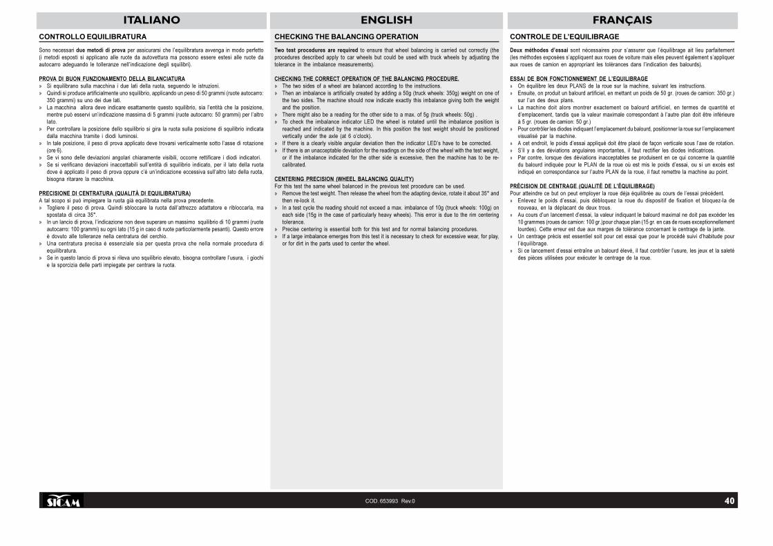
ITALIANO ENGLISH FRANÇAIS
40COD. 653993 Rev.0
CONTROLLO EQUILIBRATURA
Sono necessari due metodi di prova per assicurarsi che l’equilibratura avvenga in modo perfetto(i metodi esposti si applicano alle ruote da autovettura ma possono essere estesi alle ruote daautocarro adeguando le tolleranze nell’indicazione degli squilibri).
PROVA DI BUON FUNZIONAMENTO DELLA BILANCIATURA» Si equilibrano sulla macchina i due lati della ruota, seguendo le istruzioni.» Quindi si produce artificialmente uno squilibrio, applicando un peso di 50 grammi (ruote autocarro:
350 grammi) su uno dei due lati.» La macchina allora deve indicare esattamente questo squilibrio, sia l’entità che la posizione,
mentre può esservi un’indicazione massima di 5 grammi (ruote autocarro: 50 grammi) per l’altrolato.
» Per controllare la posizione dello squilibrio si gira la ruota sulla posizione di squilibrio indicatadalla macchina tramite i diodi luminosi.
» In tale posizione, il peso di prova applicato deve trovarsi verticalmente sotto l’asse di rotazione(ore 6).
» Se vi sono delle deviazioni angolari chiaramente visibili, occorre rettificare i diodi indicatori.» Se si verificano deviazioni inaccettabili sull’entità di squilibrio indicato, per il lato della ruota
dove è applicato il peso di prova oppure c’è un’indicazione eccessiva sull’altro lato della ruota,bisogna ritarare la macchina.
PRECISIONE DI CENTRATURA (QUALITÀ DI EQUILIBRATURA)A tal scopo si può impiegare la ruota già equilibrata nella prova precedente.» Togliere il peso di prova. Quindi sbloccare la ruota dall’attrezzo adattatore e ribloccarla, ma
spostata di circa 35°.» In un lancio di prova, l’indicazione non deve superare un massimo squilibrio di 10 grammi (ruote
autocarro: 100 grammi) su ogni lato (15 g in caso di ruote particolarmente pesanti). Questo erroreè dovuto alle tolleranze nella centratura del cerchio.
» Una centratura precisa è essenziale sia per questa prova che nella normale procedura diequilibratura.
» Se in questo lancio di prova si rileva uno squilibrio elevato, bisogna controllare l’usura, i giochie la sporcizia delle parti impiegate per centrare la ruota.
CHECKING THE BALANCING OPERATION
Two test procedures are required to ensure that wheel balancing is carried out correctly (theprocedures described apply to car wheels but could be used with truck wheels by adjusting thetolerance in the imbalance measurements).
CHECKING THE CORRECT OPERATION OF THE BALANCING PROCEDURE.» The two sides of a wheel are balanced according to the instructions.» Then an imbalance is artificially created by adding a 50g (truck wheels: 350g) weight on one of
the two sides. The machine should now indicate exactly this imbalance giving both the weightand the position.
» There might also be a reading for the other side to a max. of 5g (truck wheels: 50g) .» To check the imbalance indicator LED the wheel is rotated until the imbalance position is
reached and indicated by the machine. In this position the test weight should be positionedvertically under the axle (at 6 o’clock).
» If there is a clearly visible angular deviation then the indicator LED’s have to be corrected.» If there is an unacceptable deviation for the readings on the side of the wheel with the test weight,
or if the imbalance indicated for the other side is excessive, then the machine has to be re-calibrated.
CENTERING PRECISION (WHEEL BALANCING QUALITY)For this test the same wheel balanced in the previous test procedure can be used.» Remove the test weight. Then release the wheel from the adapting device, rotate it about 35° and
then re-lock it.» In a test cycle the reading should not exceed a max. imbalance of 10g (truck wheels: 100g) on
each side (15g in the case of particularly heavy wheels). This error is due to the rim centeringtolerance.
» Precise centering is essential both for this test and for normal balancing procedures.» If a large imbalance emerges from this test it is necessary to check for excessive wear, for play,
or for dirt in the parts used to center the wheel.
CONTROLE DE L’EQUILIBRAGE
Deux méthodes d’essai sont nécessaires pour s’assurer que l’équilibrage ait lieu parfaitement(les méthodes exposées s’appliquent aux roues de voiture mais elles peuvent également s’appliqueraux roues de camion en appropriant les tolérances dans l’indication des balourds).
ESSAI DE BON FONCTIONNEMENT DE L’EQUILIBRAGE» On équilibre les deux PLANS de la roue sur la machine, suivant les instructions.» Ensuite, on produit un balourd artificiel, en mettant un poids de 50 gr. (roues de camion: 350 gr.)
sur l’un des deux plans.» La machine doit alors montrer exactement ce balourd artificiel, en termes de quantité et
d’emplacement, tandis que la valeur maximale correspondant à l’autre plan doit être inférieureà 5 gr. (roues de camion: 50 gr.)
» Pour contrôler les diodes indiquant l’emplacement du balourd, positionner la roue sur l’emplacementvisualisé par la machine.
» A cet endroit, le poids d’essai appliqué doit être placé de façon verticale sous l’axe de rotation.» S’il y a des déviations angulaires importantes, il faut rectifier les diodes indicatrices.» Par contre, lorsque des déviations inacceptables se produisent en ce qui concerne la quantité
du balourd indiquée pour le PLAN de la roue où est mis le poids d’essai, ou si un excès estindiqué en correspondance sur l’autre PLAN de la roue, il faut remettre la machine au point.
PRÉCISION DE CENTRAGE (QUALITÉ DE L’ÉQUILIBRAGE)Pour atteindre ce but on peut employer la roue déja équilibrée au cours de l’essai précédent.» Enlevez le poids d’essai, puis débloquez la roue du dispositif de fixation et bloquez-la de
nouveau, en la déplacant de deux trous.» Au cours d’un lancement d’essai, la valeur indiquant le balourd maximal ne doit pas excéder les
10 grammes (roues de camion: 100 gr.)pour chaque plan (15 gr. en cas de roues exceptionnellementlourdes). Cette erreur est due aux marges de tolérance concernant le centrage de la jante.
» Un centrage précis est essentiel soit pour cet essai que pour le procédé suivi d’habitude pourl’équilibrage.
» Si ce lancement d’essai entraîne un balourd élevé, il faut contrôler l’usure, les jeux et la saletédes pièces utilisées pour exécuter le centrage de la roue.

ITALIANO ENGLISH FRANÇAIS
42COD. 653993 Rev.0
AUTODIAGNOSI
Sono previste delle funzioni di autodiagnosi per verificare il corretto funzionamento della macchinaequilibratrice.
Premere il tasto MENÙ e tenerlo premuto.
Appena sul display di sinistra compare la scitta tSt rilasciare immediatamente il tasto e premere(entro1,5sec) il tasto MM/INCH; si ha quindi accesso al menù di autodiagnosi che comprende leseguentifunzioni (premere il tasto MENÙ per passare da una funzione all’altra):» visualizzazione della tensione dei pick-up (rilevata durante l’ultima misura): il display
visualizzaMSr; per visualizzare i valori rilevati nell’ultima misura bisogna premere il tasto distanza(4fig.16): sul display di destra compariranno in sequenza i valori di lettura del pick-up interno, delpick-up esterno (valori da 0 a 4095), della differenza di fase (in °) e del guadagno impiegato.Per valutare il buon funzionamento dei pick-up procedere nel seguente modo:- montare sulla macchina una ruota di prova ed equilibrarla perfettamente;- applicare un peso di test singolo all’esterno (ad es. 100g) ed eseguire un lancio di prova;
al termine, controllando i valori rilevati, il valore di tensione del pick-up interno deve esseresempre più piccolo rispetto al valore di tensione del pick-up esterno ed il rapporto tra ilvalore del pick-up esterno e quello interno deve essere compreso tra 1.7-2.3; la differenzadi fase deve essere di 180° ± 1°.
» visualizzazione posizione angolare dell’albero: il display visualizza EnC; ruotando l’alberoil valore sul display di destra varia con continuità da 0 a 255 o da 0 a 200, in base al modello;
» controllo velocità dell’albero: il display visualizza SP; premendo il tasto START è possibileverificare la velocità di regime della macchina in giri al minuto (167±5rpm @ 50Hz,200±5rpm@60Hz);
» lettura segnali: per muoversi entro il menu’ utilizzare i tasti (4 e 5 fig.16); il display di sinistravisualizza in sequenza An0, An1, …, An10; valori da 0 a 4095; premendo il tasto + si passa allalettura degli ingressi analogici della DISTANZA, LARGHEZZA e DIAMETRO nella corrispondenteunità di misura.
» contatore lanci: il display visualizza Cnt; per visualizzare il conteggio dei lanci bisognapremere il tasto distanza (4 fig.16): sul display di destra compariranno in sequenza il numero dilanci totali ed il numero di lanci parziali (dall’ultima accensione della macchina);
» test display: il display visualizza LEd; test accensione led; per muoversi entro il menu’ utilizzarei tasti distanza e diametro (4-5fig.16);
» visualizzazione dati autotaratura: il display visualizza tAr; per muoversi entro il menu’utilizzare i tasti (4-5 fig.16);
» Test I/O: il display visualizza i_o; test di ingressi e uscite:- uscita magnete: il display di sinistra visualizza mag; il display di destra visualizza on
se il magnete è attivo e oFF se il magnete è a riposo;- uscita abilitazione flangia : il display di sinistra visualizza fla; il display di destra
visualizza on se l’uscita di abilitazione è attiva e oFF se non è attiva;- ingresso micro-pedale: il display di sinistra visualizza ped; il display- di destra visualizza on se il pedale è tirato verso l’alto e oFF se il pedale è a riposo;- ingresso microinterruttore protezione ruota: il display di sinistra visualizza inP; il
display di destra visualizza on se il carter è chiuso e oFF se il carter è aperto;» equilibratura momentanea di una ruota: il display visualizza rEL;
è possibile eseguire delle prove di equilibratura relativa su di una ruota senza equilibrareeffettivamente con dei contrappesi la ruota stessa:- montare sulla macchina la ruota di prova ed eseguire un primo lancio;al termine l’equilibratrice visualizza lo squilibrio reale della ruota e automaticamente acquisiscei dati di squilibrio e li annulla per tutte le misure successive.
N.B.: i valori di squilibrio visualizzati in tutte le misure successive all’attivazione di questa funzionenon sono reali, ma sono relativi allo squilibrio iniziale della ruota di prova.La funzione non è memorizzabile e si annulla spegnendo la macchina, oppure rientrando nellafunzionestessa e disattivandola premendo il tasto decremento - : il display di destra visualizzaon se la funzione è attivata e oFF se è disattivata.
AUTO-DIAGNOSIS
Auto-diagnostic functions are included to check that the balancing machine is working properly.
Press and hold down the MENU button.
As soon as tSt appears on the left display, immediately release the button and press (within 1.5 sec)the MM/INCH button. This opens the auto-diagnosis menu with the following functions (press theMENU button to scroll through the functions):» Pick-up voltage display (recorded during the last measuring cycle): the display reads MSr. To
display the figures for the last measurement press the distance button (4 fig.16). The rightdisplay shows the sequence of readings from the inside pick-up, the outside pick-up, (from 0 to4095), the phase difference (in °), and the gain employed.To check on pick-up operation, proceed as follows:- mount a test wheel on the machine and balance it perfectly.- fit a single test weight on the outside (e.g. 100g) and run a test cycle.When completed, check the readings. The inside pick-up voltage figure must always be lowerthan the outside pick-up voltage figure. Also, the ratio between the outside and inside pick-upfigures must always be between 1.7-2.3. The phase difference must be 180° ± 1°.
» Shaft angular position display: the display reads EnC. When the shaft is rotated, the rightdisplay varies constantly from 0 to 255 or from 0 to 200, depending on the model.
» Shaft speed check: the display reads SP. By pressing the START button it is possible to checkthe machine running speed in rpm (167±5rpm @ 50Hz, 200±5rpm @ 60Hz).
» Reading signals: to scroll through the menus use the buttons (4 and 5 fig.16). The left displayreads in sequence An0, An1, …, An10; figures from 0 to 4095. Pressing the + button moves tothe analogue input readings for DISTANCE, WIDTH, and DIAMETER in the corresponding unitsof measurement.
» Cycle counter: the display reads Cnt. To display the cycle count press the distance button(4 fig.16) and the right display gives in sequence the total number of cycles and partial numberof cycles (from the last time the machine was switched on).
» Test display: the display reads LEd; test lighting up of LED’s. To scroll the menus use thedistance and diameter buttons (4-5fig.16).
» Self-calibration data display: the display reads tAr. To scroll the menus use the buttons (4-5 fig.16).
» I/O test : the display reads i_o; various inputs and outputs are rested:- Magnet output: the left display reads mag; the right display reads on if the magnet is
active and oFF if the magnet is inactive.- Adapter enable output : the left display reads fla; the right display reads on if the enable
output is active and oFF if it is inactive.- Pedal microswitch input: the left display reads ped; the right display- reads on is pushed up and oFF if the pedal is in the neutral position.- Wheel guard microswitch input: the left display reads inP; the right display reads on
if the guard is closed and oFF if the guard is open.» Temporary balancing of a wheel: the display reads rEL;
relative balancing tests can be run on a wheel without actually balancing it using counter-weights;- mount the test wheel and launch a first cycle;on completion of the cycle the display shows the real imbalance of the wheel and automaticallyrecords the imbalance data and annuls the same for all subsequent measurements.
N.B.: The imbalance figures displayed in all the subsequent measurements after activation of thisfunction are not real and are relative to the initial imbalance of the test wheel.This function cannot be memorized and is cancelled when the machine is switched off or byreturning to the same function and pressing the decrease button - : the right display reads on if thefunction is active and oFF if it is inactive.
AUTODIAGNOSTIC
PPour vérifier le fonctionnement correct de l’équilibreuse on a prévu des fonctions d’autodiagnostic.
Presser la touche MENU et la tenir pressée.
Dès que le mot tSt apparaît sur l’afficheur à gauche relâcher la touche immédiatement et presser(dans 1sec,5) la touche MM/INCH; on a donc accès au menu d’autodiagnostic qui inclut les fonctionssuivantes (presser la touche MENU pour passer d’une fonction à l’autre):» affichage de la tension des pick-up (détectée pendant la dernière mesure): l’afficheur montre
MSr; pour afficher les valeurs lues pendant la dernière mesure, presser la touche distance (4fig.16): sur l’afficheur à droite apparaîtront en séquence les valeurs de lecture du pick-up intérieur,de celui extérieur (valeurs de 0 à 4095), de la différence de phase (en °) et du gain obtenu.Pour évaluer le bon fonctionnement des pick-up procéder comme suit:- monter sur la machine une roue d’essai et l’équilibrer parfaitement;- appliquer une seule masse d’essai à l’extérieur (ex. 100g) et exécuter un lancer d’essai;à la fin, en contrôlant les valeurs lues, la valeur de tension du pick-up intérieur doit toujours êtreplus petite par rapport à la valeur de tension du pick-up extérieur et le rapport entre la valeur dupick-up extérieur et celui intérieur doit être compris entre 1.7-2.3; la différence de phase doit êtrede 180° ± 1°.
» affichage de la position angulaire de l’arbre: l’afficheur montre EnC; en faisant tournerl’arbre la valeur sur l’afficheur à droite varie constamment de 0 à 255 ou de 0 à 200, selon lemodèle;
» contrôle de la vitesse de l’arbre: l’afficheur montre SP; en pressant la touche START il estpossible de vérifier la vitesse de régime de la machine en tours/minute (167±5t/min @ 50Hz,200±5t/min @60Hz);
» lecture des signalisations: pour se déplacer dans le menu utiliser les touches (4 et 5 fig.16);l’afficheur à gauche montre en séquence An0, An1, …, An10; valeurs de 0 à 4095; en pressantla touche + on passe à la lecture des entrées analogiques de la DISTANCE, LARGEUR etDIAMETRE dans l’unité de mesure correspondante.
» conteur de lancers: l’afficheur montre Cnt; pour afficher le nombre de lancers presser latouche distance (4 fig.16): sur l’afficheur à droite apparaîtront en séquence le nombre de lancerstotal et le nombre de lancers partiel (depuis le dernier allumage de la machine);
» test afficheur: l‘afficheur montre LEd; test d’allumage led; pour se déplacer dans le menuutiliser les touches distance et diamètre (4-5fig.16);
» affichage des données d’auto-tarage: l’afficheur montre tAr; pour se déplacer dans le menuutiliser les touches (4-5 fig.16);
» Test I/O : l’afficheur montre i_o; test de quelques entrées et sorties:- sortie aimant: l’afficheur à gauche montre mag; l’afficheur à droite montre on si l’aimant
est actif et oFF si l’aimant est à repos;- sortie activation plateau : l’afficheur à gauche montre fla; l’afficheur à droite montre on
si la sortie de l’activation est établie et oFF si elle ne l’est pas;- entrée micro-pédale: l’afficheur à gauche montre ped; l’afficheur à droite montre- on si la pédale est tirée vers le haut et oFF si la pédale est à repos;- entrée microinterrupteur protection roue: l’afficheur à gauche montre inP; l’afficheur
à droite montre on si le carter est fermé et oFF si le carter est ouvert;» équilibrage momentané d’une roue: l’afficheur montre rEL; il est possible d’exécuter des
essais d’équilibrage relatifs sur une roue sans réellement équilibrer la roue avec des masses:- monter la roue d’essai sur la machine et exécuter un premier lancer;à la fin l’équilibreuse affiche le balourd réel de la roue, acquiert automatiquement les donnéesde balourd et les annule pour toutes les mesures successives.
Note: les valeurs de balourd affichées en toutes les mesures successives à l’activation de cettefonction ne sont pas réelles mais elles sont relatives au balourd initial de la roue d’essai.La fonction n’est pas mémorisable et s’annule en éteignant la machine, ou en revenant dans lafonction et en la désactivant en pressant la touche décrément - : l’afficheur à droite montre on sila fonction est activée et oFF si elle est désactivée.

ITALIANO ENGLISH SBM 850
44COD. 653993 Rev.0
MANUTENZIONE ORDINARIA
pulizia e manutenzione della macchina a cura dell’utilizzatore
Per garantire l’efficienza della macchina e per il suo corretto funzionamentoè indispensabile effettuare la pulizia e la periodica manutenzione ordi-naria. Le operazioni di manutenzione ordinaria devono essere effettuatedall’utilizzatore in accordo alle istruzioni del costruttore di seguito riportate:
Prima di procedere a qualsiasi operazione di pulizia e manutenzione,spegnere la macchina tramite l’interruttore generale e togliere la
spina dalla presa di corrente
PARTI MECCANICHEIl dispositivo adattatore a coni dell’asse e i dispositivi di serraggio vannomantenuti puliti e devono essere leggermente lubrificati con olio non corrosivo,anche quando non sono impiegati. La qualità dell’equilibratura dipendeconsiderevolmente dalla loro condizione.Lubrificatore:controllare e mantenere il livello dell’olio nel Lubrificatore,livello che non deve superare i valori min.e max ivi indicati. Se necessarioaggiungere olio fluido.Filtro Aria: periodicamente scaricare l’acqua di condensa formatasi nel filtroaria.
TRASPORTO E MOVIMENTAZIONE
Qualora si renda necessario il trasporto o la movimentazione dellamacchina, adottare le necessarie precauzioni!
Per le modalità di imbragamento e sollevamento della macchina, fareriferimento alle indicazioni della figura 21.
ACCANTONAMENTO E ROTTAMAZIONE
PERIODI DI INATTIVITA’Qualora si decida di accantonare provvisoriamente la macchina, o comunquedurante i periodi in cui l’attrezzatura non è in funzione, togliere la spina dalla
presa di corrente !
ACCANTONAMENTO DEFINITIVOAllorché si decida di non utilizzare più questa macchina, si raccomanda direnderla inoperante asportando il cavo dell’alimentazione elettrica dopo aver
tolto la spina dalla presa.
ROTTAMAZIONEEssendo l’equilibratrice assimilabile a rifiuto di tipo speciale, scomporre inparti omogenee e smaltire secondo le leggi vigenti.
21
ROUTINE MAINTENANCE
cleaning the machine and user maintenance
In order to guarantee the correct operation and efficiency of the machine it isessential to carry out periodic routine maintenance. Routine maintenanceoperations must be conducted by the user in accordance with themanufacturer’s instructions given below.
Before carrying out any maintenance or cleaning operations, switch
off the machine using the main switch and remove the plug from
the socket.
MECHANICAL PARTSThe axle cone adapter device and the screw devices must be kept cleanand lightly lubricated with non-corrosive oil even when not being used. Thequality of the balancing depends significantly on the condition of these parts.Lubricator: check and adjust the level of oil in the lubricator. The level shouldnot go outside the minimum and maximum levels indicated on it. Top up ifnecessary.Air filter: periodically release the condensation which accumulates in the airfilter.
MOVEMENT AND TRANSPORT
Whenever it is necessary to move or transport the machine all neces-sary precautions must be taken!
For methods of harnessing and lifting the machine see figure 21.
STORAGE AND SCRAPPING
PERIODS OF INACTIVITYWhenever the machine is to be stored temporarily and during periods in whichit is not in use, remove the electrical plug from the socket.
DEFINITIVE STORAGEIf the decision is taken to stop using the machine it should be made inopera-tive by detaching the electrical supply cable after removing the plug from the
socket.
SCRAPPINGThe wheel balancer is categorised as special refuse and it should thereforebe divided into homogenous parts and disposed of according to the laws inforce.
TABELLA OLII / OIL TABLE / TABLEAU DES HUILES
EMPFOHLENE SCHMIERMITTEL-TABELLE / TABLA DE ACEITES / ÒÀÁËÈÖÀ ÌÀÑÅË
Olio Lubrificante per Sistema PneumaticoLubricating oil type for pneumatic systemHuile lubrifiante pour Système PneumatiqueSchmieröl für das DruckluftsystemAceite lubricante para sistema neumáticoÑìàçî÷íîå ìàñëî äëÿ ïíåâìàòè÷åñêîé ñèñòåìû
Il costruttore non risponderà degli eventuali danni causati dall’utilizzo di altri olii.The manufacturer will not be responsible for any damage resulting from the use of different oils.Le constructeur ne sera pas tenu responsable pour les dommages éventuels causés par l’utilisation d’autres huiles.Der Hersteller haftet in keiner Weise für Schäden, die durch die Verwendung von anderen Schmiermitteln entstehen.El fabricante no responderà de los daños causados por el uso de otros aceites.Ôèðìà-ïðîèçâîäèòåëü íå íåñåò îòâåòñòâåííîñòè çà âîçìîæíûå ïîâðåæäåíèÿ âûçâàííûå èñïîëüçîâàíèåì äðóãèõ ìàñåë.
ESSO FEBIS K 32
ISO 32
CARATTERISTICHE TECNICHETECHNICAL CHARACTERISTICSCARACTERISTIQUES TECHNIQUESTECHNISCHE MERKMALECARACTERISTICAS TECNICASÒÅÕÍÈ×ÅÑÊÈÅ ÕÀÐÀÊÒÅÐÈÑÒÈÊÈ

SBM 850N.653952 Rev. 1

SBM 850N.653993 Rev. 0
Kwik-Way 85 HD Balancer: 800-553-5953

SBM 850N.652896 Rev. 4
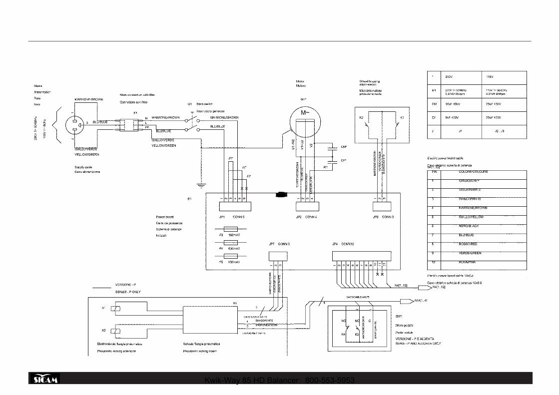
SBM 850N.653736Rev. 1SCHEMA ELETTRICO EQUILIBRATRICE SBM 850 A 115/230VSBM 850 BALANCING MACHINE ELECTRIC DIAGRAM AT 115/230VDIAGRAMA DE CONEXION BALANCEADORA SBM 850 A 115/ 230V
Kwik-Way 85 HD Balancer: 800-553-5953

SBM 850N.653737Rev. 0SCHEMA ELETTRICO EQUILIBRATRICE SBM 850 A 115/230VSBM 850 BALANCING MACHINE ELECTRIC DIAGRAM AT 115/230VDIAGRAMA DE CONEXION BALANCEADORA SBM 850 A 115/ 230V

OPTIONALN.652899Rev. 3
Kwik-Way 85 HD Balancer: 800-553-5953

SBM 850N.652890Rev. 0