Embed Size (px)
Citation preview

ledoM Frequency WRS Gain
TLA4100
TLA4200
800-960 MHz1710-2700 MHz
800-960 MHz1710-2700 MHzGPS = 1575.42 MHz
g bandnitareporevo1:2<
<2:1 over operating band 5dBi (using a 1m2 ground plane)
5dBi (using a 1m2 ground plane)
Typical VSWR response800-2800 MHz @ 1800 MHz CF
Overall dimensions mm 100(W) x 200(L) x 90(H) includes gasket
lairetamemodaR UV Stabilised Plastic Moulding
tnuoM 4 x M6 screws (not included)
Termination Antenna Port = Fixed N Female (TLA4100)GPS Port = Fixed TNC female (TLA4200)
©2008 RF Industries Pty Ltd
The TLA4100/4200 can be installed with or without a ground plane. Maximum gain is achieved when a ground plane of greater than 1m2 is used.
TLA4100/TLA4200 Low Profile Transit Antennas
800-960 MHz1710-2700 MHzGPS for TLA4200
INS-40051-1
+28001800800
Antenna Assembly Drawing:
The TLA4100/4200 Antenna is designed specifically for rail, light rail & bus applications and other similarly demanding transit or stationary applications.
Fitting Instructions:a) Determine area (with clearance) required to mount the antenna, ensuring a flat area is chosen. Ideally the antenna will be installed at the highest position on the roof structure with no obstructions at the same height for at least 1m around the antenna.
b) The Antenna is shaped with minimal wind loading in mind. Mount the antenna with the longest dimension of the antenna running parallel with direction of travel of the train, light rail vehicle or bus.
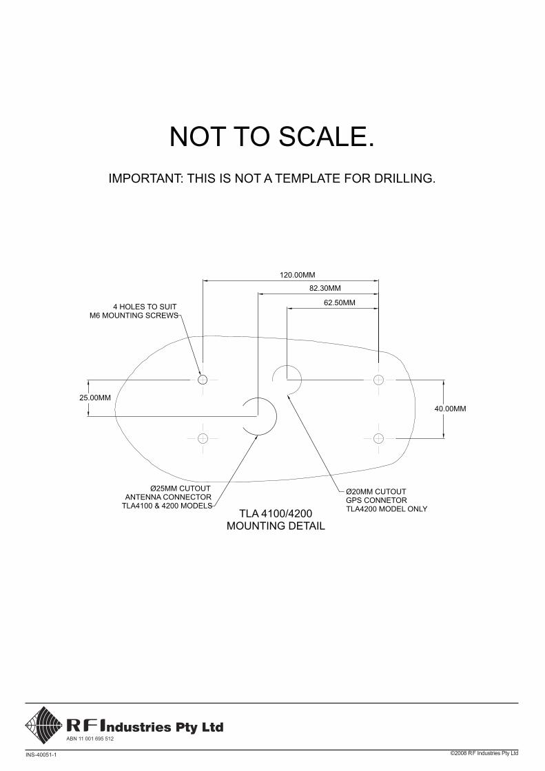
c) Use the Mounting Detail drawing as a guide (or the actual antenna base plate) to mark out the mounting hole positions for drilling. Ensure no obstructions inside the roof structure at the mounting position. Drill holes to accommodate M6 screws.
d) Use the Mounting Detail drawing as a guide (or the actual antenna base plate) to mark out the connector position(s) for drilling / cutting / punching. Ensure no obstructions inside the roof structure at the mounting position. Drill / cut / punch holes to accommodate the connector(s). Hole diameters shown on the Mounting detail drawing allow room for diameter of the mating connector(s). ****Only the TLA4200 requires a hole for the GPS connector.
e) Fix the antenna in place using 316 Stainless Steel M6 Hex Drive Cap Screws (not supplied) in the required length. Further details in the Antenna Assembly drawing.
f) Using appropriate test equipment, check the VSWR.
g) Connect to GPS receiver and test functionality (TLA4200).
h) To meet high voltage protection specifications for applications involving overhead wires, it is necessary to ensure conductive contact between the base of the antenna and the conductive roof of the carriage / vehicle.
RECOMMENDED STAINLESS STEEL 316 M6 HEX DRIVE CAPSCREW NOT SUPPLIED, LENGTH AS REQUIRED, TORQUE TO 6NM.
THE APPLICATION OF THREAD LOCKER 262 TO THREAD IS RECOMMENDED ON INSTALLATION, OR USE OF NYLOC NUTS FOR HIGH VIBRATION ENVIRONMENTS.
SUPPLIED SCREW SEALS TO BE FITTED TO SCREW AS SHOWN ON INSTALLATION.
©2008 RF Industries Pty LtdINS-40051-1
40.00MM
62.50MM
82.30MM
120.00MM
25.00MM
4 HOLES TO SUITM6 MOUNTING SCREWS
TLA 4100/4200MOUNTING DETAIL
Ø20MM CUTOUTGPS CONNETORTLA4200 MODEL ONLY
Ø25MM CUTOUTANTENNA CONNECTOR
TLA4100 & 4200 MODELS
NOT TO SCALE.IMPORTANT: THIS IS NOT A TEMPLATE FOR DRILLING.