Embed Size (px)
Citation preview

C7 RF Transceiver Module
FEATURES
78 selectable RF channels (2403 to 2480 MHz)
20mm x 20mm drop-in module with F antenna
Ultra low power operation
Simple sync/async serial interface
Programmable output power up to +4 dBm
Excellent receiver sensitivity -86 dBm
1 Mbps RF data rate, GFSK modulation
Up to 8 ANT channels
Broadcast, acknowledged, or burst data transmissions
Built-in ANT-FS (file share) with AES-128 encryption
ANT channel combined message rate up to 200Hz (8byte
data payload)
Minimum message rate per ANT channel 0.5Hz
Burst transfer rate up to 20Kbps (true data throughput)
Up to 3 public, managed and/or private network keys
High resolution proximity pairing and RSSI reading
2 V to 3.6V supply voltage range
-40°C to +85°C operating temperature
Pin compatible with ANT AP2, AT3 and AP1 modules
Radio regulatory approval for major markets
RoHS compliant
APPLICATIONS
Network controllers and data hubs.
Complex sensors in health and fitness
FAMILY MEMBERS
ANTC782M5IB – 8 ANT channels; Molex
Connector
ANTC782M4IB – 8 channels, surface mount
ANT NETWORK CONFIGURATIONS
1 12
2 11
3 10
4 9
5 8
6 7
M
PEER
TO
PEER
STAR
PRACTICAL MESH
SHARED
BI-DIRECTIONAL
8 7 6
9
10
11
12
13
14 15 16
5
4
3
2
1
SCANNING MODEANT-FS
(Secure Authenticated)
1 12
2 11
3 10
4 9
? 8
6 7
M
AD-HOC
AUTO
SHARED
1 12
2 11
3 10
4 9
5 8
6 7
M
SHARED
UNI-DIRECTIONAL
n
Bidirectional
Acknowledged
BROADCAST
SHARED CLUSTERSensor
Hub
Relay
D00001445 Rev 1.3
Page 2 of 23 ANT C7 RF Transceiver Module, Rev 1.3
dynastream.com thisisant.com
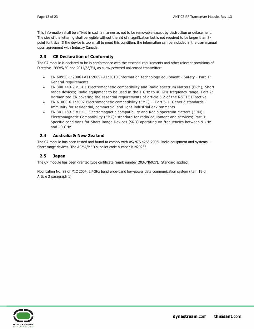
Table of Contents
1. ANT C7 Module .............................................................................................................................................. 5
1.1 Production Code ............................................................................................................................. 5
1.2 Interface ........................................................................................................................................ 6
1.3 Application MCU connection............................................................................................................. 7
1.3.1 Async Mode ...................................................................................................................... 7
1.3.2 Byte Sync Mode ................................................................................................................ 8
1.3.3 Bit Sync Mode .................................................................................................................. 9
1.3.4 External Memory Connection ........................................................................................... 10
1.4 Mounting Guideline ....................................................................................................................... 10
1.5 Reflow Guideline ........................................................................................................................... 10
1.6 Pick-n-Place .................................................................................................................................. 10
2. Regulatory Approval ...................................................................................................................................11
2.1 United States ................................................................................................................................ 11
2.2 Industry Canada Compliance ......................................................................................................... 11
2.3 CE Declaration of Conformity ......................................................................................................... 12
2.4 Australia & New Zealand ............................................................................................................... 12
2.5 Japan ........................................................................................................................................... 12
3. Electrical Specifications ..............................................................................................................................13
3.1 Absolute Maximum Ratings (1) ........................................................................................................ 13
3.2 Recommended Operating Conditions ............................................................................................. 13
3.3 ELECTRICAL CHARACTERISTICS.................................................................................................... 13
3.4 RF Characteristics ......................................................................................................................... 14
3.5 Application Specific Power Usage ................................................................................................... 15
3.6 Calculating the Average Current Consumption and Battery Life ....................................................... 16
4. Mechanical Drawings ..................................................................................................................................18
5. Technical Support .......................................................................................................................................23
5.1 ANT Forum ................................................................................................................................... 23
5.2 Public Technical References ........................................................................................................... 23
5.3 ANT Developer’s Zone ................................................................................................................... 23
5.4 ANT Social Media .......................................................................................................................... 23

ANT C7 RF Transceiver Module, Rev 1.3 Page 3 of 23
dynastream.com thisisant.com
Notices and Restricted Use Information
Information contained in this document is provided only for your ("Customer" or “you”) convenience and may be
superseded by updates. It is your responsibility to ensure that your application meets with your specifications.
Dynastream Innovations Inc. ("DYNASTREAM") makes no representations or warranties of any kind whether
express or implied, written or oral, statutory or otherwise, related to the information, including but not limited to
its condition, quality, performance, merchantability or fitness for purpose. DYNASTREAM disclaims all liability
arising from this information and its use.
DYNASTREAM does not assume any responsibility for the use of the described ANT RF module (“the Module(s)”).
Dynastream makes no representation with respect to the adequacy of the module in low-power wireless data
communications applications or systems. Any Products using the Module must be designed so that a loss of
communications due to radio interference or otherwise will not endanger either people or property, and will not
cause the loss of valuable data. DYNASTREAM assumes no liability for the performance of products which are
designed or created using the Modules.
The Modules are not designed, intended, or authorized for use as components in systems intended for surgical
implant into the body, or other applications intended to support or sustain life, or for any other application in
which the failure of the Module could create a situation where personal injury or death may occur. If you use the
Modules for such unintended and unauthorized applications, you do so at your own risk and you shall indemnify
and hold DYNASTREAM and its officers, employees, subsidiaries, affiliates, and distributors harmless against all
claims, costs, damages, and expenses, and reasonable attorney fees arising out of, directly or indirectly, any claim
of personal injury or death associated with such unintended or unauthorized use, even if such claim alleges that
DYNASTREAM was negligent regarding the design or manufacture of the Product.
The information disclosed herein is the exclusive property of DYNASTREAM, and is not to be reproduced and/or
distributed without the written consent of DYNASTREAM. No part of this publication may be reproduced or
transmitted in any form or by any means including electronic storage, reproduction, execution or transmission
without the prior written consent of DYNASTREAM. The recipient of this document by its retention and use agrees
to respect the security status of the information contained herein.
DYNASTREAM believes the information contained herein is correct and accurate at the time of its release.
However, the information contained in this document is subject to change without notice and should not be
construed as a commitment by DYNASTREAM unless such commitment is expressly given in a covering document.
©2014 Dynastream Innovations Inc. All Rights Reserved. ANT is a registered trade mark of Dynastream
Innovations Inc.

Page 4 of 23 ANT C7 RF Transceiver Module, Rev 1.3
dynastream.com thisisant.com
ANT™ Overview
ANT™ is a practical wireless sensor network protocol running on 2.4 GHz ISM band. Designed for ultra low power,
ease of use, efficiency and scalability, ANT easily handles peer-to-peer, star, tree and practical mesh topologies.
ANT provides reliable data communications, flexible and adaptive network operation and cross-talk immunity. The
protocol stack of ANT is extremely compact, requiring minimal microcontroller resources and considerably reducing
system costs.
ANT provides carefree handling of the Physical, Network, and Transport OSI layers. In addition, it incorporates key
low-level security features that form the foundation for user-defined, sophisticated, network-security
implementations. ANT ensures adequate user control while considerably lightening the computational burden in
providing a simple yet effective wireless networking solution.
ANT supports public, managed and private network architectures with 232 uniquely addressable devices possible,
ensuring that each device can be uniquely identified from each other in the same network.
ANT is proven with an installed base of over multimillion nodes in ultra low power sensor network applications in
sport, fitness, home and industrial automation. The ANT solutions are available in chips, chipsets and modules to
suit a wide variety of application needs.
The complete description of ANT message protocol is found in the document “ANT Message Protocol and Usage”.
The serial interface details are provided in the document “Interfacing with ANT General Purpose Chipsets and
Modules”. Both documents are available on www.thisisant.com.
ANT+ and ANT+ Alliance
ANT+ is the open application layer on the top of the ANT stack. It standardizes communications and facilitates
interoperability between a wide array of personal sports, wellness and lifestyle monitoring devices. ANT+ defines
device profiles that specify access, data formats, and channel parameters.
The ANT+ Alliance is comprised of companies who have adopted the ANT+ promise of interoperability. The
Alliance ensures standardized communication through optimized brand value and partnerships with other top tier
companies and products.
Application / PresentationLayers
Higher Level Security
Network / Transport &Low Level Security
Data Link Layer
Physical Layer}Implemented
by ANT
}User Defined

ANT C7 RF Transceiver Module, Rev 1.3 Page 5 of 23
dynastream.com thisisant.com
1. ANT C7 Module
The ANT C7 module is a drop-in module using the CC2571, an ANT network processor from Texas Instruments.
The chip is able to support up to 8 independent ANT channels and for the first time offers the following features
embedded:
Integrated ANT File Share (ANT-FS) functions for exchanging data records
AES-128 data encryption on file transfers
Maximum +4dBm transmission power
High resolution RSSI reading
An F PCB antenna being integrated on the small-sized 20mm by 20mm board, the module has been certified to
comply with radio regulation or standards covering global markets include North America, Europe, Australia and
New Zealand.
The ANT C7 module eases the burden of extensive RF design and regulatory compliance testing for application and
system developers, allowing quicker time to market. The module is ideally suited for control or hub nodes of a
wireless sensor network.
Incorporated in the C782MxIB module product family are several new generation ANT core stack enhancements:
Background scanning
Continuous scanning mode
High density node support
Improved channel search
Channel ID management
Improved transmission power control
Frequency agility
Proximity acquisition
The C782MxIB module is useful for chip evaluation of both CC2570 and CC2571 from Texas Instruments.
The C7 modules are currently available in the following varieties.
Module ANT chip
Used Description Packaging Option
ANTC782M4IB CC2571 Surface mountable, 8 ANT channels,
20x20mm, industrial temperature range
Tray: 20 modules on a tray
Reel: 800 modules taped on a 13” reel
ANTC782M5IB CC2571 With Molex connector, 8 ANT channels,
20x20mm, industrial temperature range
Tray: 20 modules on a tray
1.1 Production Code
For technical support and customer service purposes, a production code of six characters is printed on the product
sticker as illustrated below.

Page 6 of 23 ANT C7 RF Transceiver Module, Rev 1.3
dynastream.com thisisant.com
1.2 Interface
The module may be connected to the user’s host controller using the 17 pin-out assignment (surface mount) style
or the 20-pin Molex header connection style provided below:
Surface Mount Pin
Molex Header Pin
Pin Name Async Mode Sync Mode Description
1 6 EE_GND*
EEPROM
GND EEPROM GND GND for external EEPROM
2 10 RST RST RST Reset the device
3 1 Vcc Vcc Vcc Power supply source
4 19 GND GND GND Power supply ground
5 8 EE_MISO* EEPROM
MISO
EEPROM
MISO MISO for external EEPROM
6 17 SUSPEND
/ SRDY SUSPEND SRDY
Async -> Suspend control
Sync -> Serial port ready
7 15 SLEEP/ MRDY SLEEP MRDY Async -> Sleep mode enable
Sync -> Message ready indication
8 13 EE_CS* EEPROM
Chip Select
EEPROM Chip
Select Chip Select for External EEPROM
9 11 PORTSEL PORTSEL
(Tie to GND)
PORTSEL
(Tie to Vcc)
Asynchronous or synchronous port
select
10 7 BR2/SCLK
BR2 SCLK
Async -> Baud rate selection
Sync -> Clock output signal
11 4 TXD0/SOUT TXD0 SOUT Async -> Transmit data signal
Sync -> Data output
12 3 RXD0/SIN RXD0 SIN Async -> Receive data signal
Sync -> Data input
13 5 BR1/SFLOW BR1 SFLOW
Async -> Baud rate selection
Sync -> Bit or byte flow control
select
14 9 BR3 BR3 SPEEDSEL Async -> Baud rate selection
Sync - > Speed selection
15 14 EE_CLK* EEPROM
clock
EEPROM
clock Clock for External EEPROM
16 12 EE_MOSI* EEPROM
MOSI
EEPROM
MOSI MOSI for external EEPROM
17 2 RTS/SEN RTS SEN Async -> Request to send
Sync -> Serial enable signal
16,18,20 NC NC NC No connection
* Note: Leave these pins not connected if EEPROM is not present.
The speed of the byte-Sync mode can be set to either 500KHz or 4MHz by setting SPEEDSEL. Please refer to the
table below.
SPEEDSEL Byte-Sync Speed
0 500KHz
1 4MHz

ANT C7 RF Transceiver Module, Rev 1.3 Page 7 of 23
dynastream.com thisisant.com
The baud rate of the asynchronous communication is controlled by the speed select signals BR1, BR2 and BR3.
Please refer to the table below.
BR3 BR2 BR1 Baud Rate
0 0 0 4800
1 0 1 9600
0 1 0 19200
0 0 1 38400
0 1 1 50000
1 1 1 57600
1 0 0 115200
1.3 Application MCU connection
Please refer to “Interfacing with ANT General Purpose Chipsets and Modules” and “CC2571 Datasheet”. The
following sample designs show the proper electrical connectivity of an ANT C7 module to an application
microcontroller, using TI MSP430F1232 as example.
1.3.1 Async Mode
Notes:
Module RXD and TXD connected directly to hardware USART of microcontroller.

Page 8 of 23 ANT C7 RF Transceiver Module, Rev 1.3
dynastream.com thisisant.com
Switches on baud rate selection pins (BR1, BR2 and BR3) are for ease of use only. They can
be connected directly to the logic level of interest.
RTS can be connected to an interrupt pin for convenience in some applications. (Interrupt
pins located on Port 1&2 on the MSP430F1232)
1.3.2 Byte Sync Mode
Notes:
Module SOUT, SIN, and SCLK connected directly to hardware USART of microcontroller.
SEN needs to be on an interrupt capable I/O pin on the microcontroller. (Interrupt pins
located on Port 1&2 on the MSP430F1232)

ANT C7 RF Transceiver Module, Rev 1.3 Page 9 of 23
dynastream.com thisisant.com
1.3.3 Bit Sync Mode
Notes:
All interface signals are connected directly to I/O pins on the microcontroller.
SCLK and SEN need to be on an interrupt capable I/O pin on the microcontroller. (Interrupt
pins located on Port 1&2 on the MSP430F1232)

Page 10 of 23 ANT C7 RF Transceiver Module, Rev 1.3
dynastream.com thisisant.com
1.3.4 External Memory Connection
The ANT C7 has ANT-FS Client functionality embedded directly on the module. This includes the over-the-air ANT-
FS protocol extension and the required file system utilities to manage stored data in non-volatile storage. An
external EEPROM can be directly connected to the C7 module. Raw files can be sent and managed by the C7
module and downloaded over ANT-FS as desired. The diagram below depicts how to connect an external EEPROM
to the C7 module. The connection is SPI. Please note that only EEPROM (not flash) is supported.
The file system and ANT-FS protocol are managed by using an extended version of the ANT/Host serial protocol.
For complete details on how to use this protocol please consult the ANT document “FS_ANTFS Serial Message”.
The extended Host/ANT interface uses a 2 byte message ID to identify FS and ANT-FS specific messages. The
packet structure is detailed the “Integrated ANT-FS Interface Control” document”.
1.4 Mounting Guideline
Refer to the recommended footprint drawing in section 4.
To connect to ANTC782M5IB, the mating socket to use is the Molex 52991-0208.
1.5 Reflow Guideline
ANTC7M4IB module is rated at moisture sensitive level 3 (MSL=3). To handle and use these modules, please
follow the standard IPC/JEDEC J-STD-033B.1, “Handling, Packing, Shipping and Use of Moisture/Reflow Sensitive
Surface Mount Devices”.
To reflow, it is recommended that the peak solder joint/pad temperatures do NOT exceed 240ºC. If possible, pre-
heat the assembly within the oven profile for ~30 seconds at ~150 ºC. Follow the solder paste manufacturer’s
recommendations, especially regarding temperature ramp rate and the time above liquidus.
1.6 Pick-n-Place
ANTC7M4IB module has the package option of 800 modules on a JEDEC standard 13” reel to facilitate machine
pick and place.

ANT C7 RF Transceiver Module, Rev 1.3 Page 11 of 23
dynastream.com thisisant.com
2. Regulatory Approval
The ANT C7 module has received regulatory approvals in the United States (FCC) and Canada (IC), and has been
verified to conform to the appropriate regulations in Europe, Australia and New Zealand. Such approvals allow the
user to place the module inside a finished product and, in most cases, not require regulatory testing for an
intentional radiator, provided no changes or modifications are made to the module circuitry. This does not
preclude the possibility that some other form of authorization or testing may be required for the finished product.
Changes or modifications could void the user’s authority to operate the equipment. The end user must comply
with all of the instructions provided by the Grantee, which indicate installation and/or operating conditions
necessary for compliance.
2.1 United States
The ANT C7 module has been tested and found to comply with the limits for a Class B digital device, pursuant to
Part 15 of the FCC Rules. These limits are designed to provide reasonable protection against harmful interference
in a residential installation. This equipment generates, uses, and can radiate radio frequency energy and, if not
installed and used in accordance with the instructions, may cause harmful interference to radio communications.
However, there is no guarantee that interference will not occur in a particular installation. If this equipment does
cause harmful interference to radio or television reception, which can be determined by turning the equipment off
and on, the user is encouraged to try to correct the interference by one of the following measures:
- Reorient or relocate the receiving antenna.
- Increase the separation between the equipment and receiver.
- Connect the equipment into an outlet on a circuit different from that to which the receiver is connected.
- Consult the dealer or an experienced radio/TV technician for help.
The C7 module complies with Part 15 of the FCC Rules. Operation is subject to the following two conditions: (1)
This device may not cause harmful interference, and (2) this device must accept any interference received,
including interference that may cause undesired operation.
The C7 module does not contain any user-serviceable parts. Unauthorized repairs or modifications could result in
permanent damage to the equipment, and void your warranty and your authority to operate this device under Part
15 regulations.
The C7 module is labelled with its own FCC ID, O6R1823 (note: First Character is the letter O, not the # 0.) If the
FCC ID is not visible when the module is installed inside another device, then the outside of the device into which
the module is installed must also display a label referring to the enclosed module. This exterior label can use
wording such as the following: “Contains Transmitter Module FCC ID: O6R1823” or “Contains FCC ID: O6R1823”.
Any similar wording that expresses the same meaning may be used.
2.2 Industry Canada Compliance
This device complies with Industry Canada licence-exempt RSS standard(s). Operation is subject to the following
two conditions: (1) this device may not cause interference, and (2) this device must accept any interference,
including interference that may cause undesired operation of the device.
(Le présent appareil est conforme aux CNR d'Industrie Canada applicables aux appareils radio exempts de licence.
L'exploitation est autorisée aux deux conditions suivantes : (1) l'appareil ne doit pas produire de brouillage, et (2)
l'utilisateur de l'appareil doit accepter tout brouillage radioélectrique subi, même si le brouillage est susceptible
d'en compromettre le fonctionnement.)
To comply with Industry Canada regulations, it is required that product containing the C7 module display a label
referring to the enclosed module. This exterior label can use wording similar to the following: “Contains IC:
3797A-1823”
Page 12 of 23 ANT C7 RF Transceiver Module, Rev 1.3
dynastream.com thisisant.com
This information shall be affixed in such a manner as not to be removable except by destruction or defacement.
The size of the lettering shall be legible without the aid of magnification but is not required to be larger than 8-
point font size. If the device is too small to meet this condition, the information can be included in the user manual
upon agreement with Industry Canada.
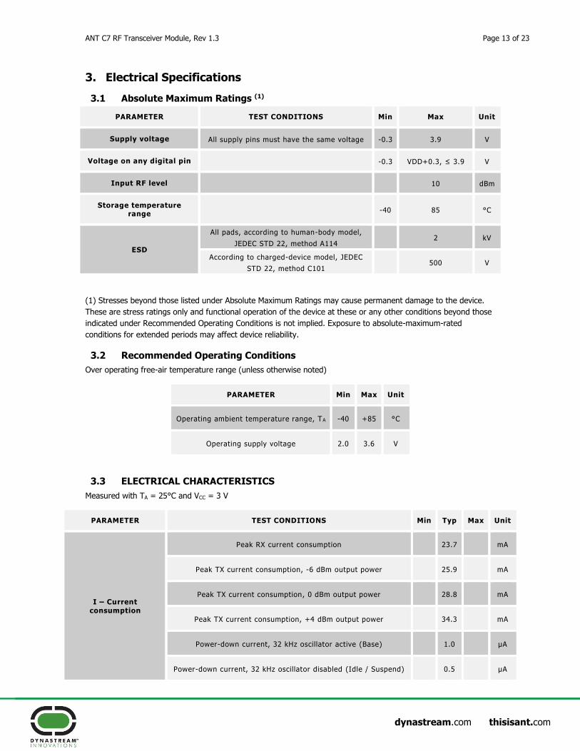
2.3 CE Declaration of Conformity
The C7 module is declared to be in conformance with the essential requirements and other relevant provisions of
Directive 1999/5/EC and 2011/65/EU, as a low-powered unlicensed transmitter:
EN 60950-1:2006+A11:2009+A1:2010 Information technology equipment - Safety - Part 1:
General requirements
EN 300 440-2 v1.4.1 Electromagnetic compatibility and Radio spectrum Matters (ERM); Short
range devices; Radio equipment to be used in the 1 GHz to 40 GHz frequency range; Part 2:
Harmonized EN covering the essential requirements of article 3.2 of the R&TTE Directive
EN 61000-6-1:2007 Electromagnetic compatibility (EMC) -- Part 6-1: Generic standards -
Immunity for residential, commercial and light-industrial environments
EN 301 489-3 V1.4.1 Electromagnetic compatibility and Radio spectrum Matters (ERM);
Electromagnetic Compatibility (EMC); standard for radio equipment and services; Part 3:
Specific conditions for Short-Range Devices (SRD) operating on frequencies between 9 kHz
and 40 GHz
2.4 Australia & New Zealand
The C7 module has been tested and found to comply with AS/NZS 4268:2008, Radio equipment and systems –
Short range devices. The ACMA/MED supplier code number is N20233
2.5 Japan
The C7 module has been granted type certificate (mark number 203-JN6027). Standard applied:
Notification No. 88 of MIC 2004, 2.4GHz band wide-band low-power data communication system (item 19 of
Article 2 paragraph 1)
ANT C7 RF Transceiver Module, Rev 1.3 Page 13 of 23
dynastream.com thisisant.com
3. Electrical Specifications
3.1 Absolute Maximum Ratings (1)
PARAMETER TEST CONDITIONS Min Max Unit
Supply voltage All supply pins must have the same voltage -0.3 3.9 V
Voltage on any digital pin -0.3 VDD+0.3, ≤ 3.9 V
Input RF level 10 dBm
Storage temperature range
-40 85 °C
ESD
All pads, according to human-body model,
JEDEC STD 22, method A114 2 kV
According to charged-device model, JEDEC
STD 22, method C101 500 V
(1) Stresses beyond those listed under Absolute Maximum Ratings may cause permanent damage to the device.
These are stress ratings only and functional operation of the device at these or any other conditions beyond those
indicated under Recommended Operating Conditions is not implied. Exposure to absolute-maximum-rated
conditions for extended periods may affect device reliability.
3.2 Recommended Operating Conditions
Over operating free-air temperature range (unless otherwise noted)
PARAMETER Min Max Unit
Operating ambient temperature range, TA -40 +85 °C
Operating supply voltage 2.0 3.6 V
3.3 ELECTRICAL CHARACTERISTICS
Measured with TA = 25°C and VCC = 3 V
PARAMETER TEST CONDITIONS Min Typ Max Unit
I – Current consumption
Peak RX current consumption 23.7 mA
Peak TX current consumption, -6 dBm output power 25.9 mA
Peak TX current consumption, 0 dBm output power 28.8 mA
Peak TX current consumption, +4 dBm output power 34.3 mA
Power-down current, 32 kHz oscillator active (Base) 1.0 µA
Power-down current, 32 kHz oscillator disabled (Idle / Suspend) 0.5 µA

Page 14 of 23 ANT C7 RF Transceiver Module, Rev 1.3
dynastream.com thisisant.com
3.4 RF Characteristics
Measured with TA = 25°C and VCC = 3 V
PARAMETER TEST CONDITIONS Min Typ Max Unit
RF frequency range Programmable in 1 MHz steps 2400 2495 MHz
Data rate and modulation format 1 Mbps, GFSK, 160 kHz deviation
Receive Section
1 Mbps, GFSK, 160-kHz deviation. Measured TA = 25°C, VCC= 3 V, and fC = 2440 MHz, unless otherwise noted.
PARAMETER TEST CONDITIONS Min Typ Max Unit
Receiver sensitivity 0.1% BER -86 dBm
Saturation 10 dBm
Co-channel rejection -9 dB
Adjacent-channel rejection ± 2 MHz 23 dB
Alternate-channel rejection ± 4 MHz 39 dB
Frequency error tolerance (1) Including both initial tolerance and drift -150 150 kHz
Symbol rate error tolerance (2) -50 +50 ppm
Spurious emission. Only largest spurious emission stated within each band.
Conducted measurement with a 50 Ω single-ended load. -70 dBm
(1) Difference between center frequency of the received RF signal and local oscillator frequency.
(2) Difference between incoming symbol rate and the internally generated symbol rate
Transmit Section
Measured with TA = 25°C, VCC = 3 V, and FC = 2440 MHz unless otherwise noted.
PARAMETER TEST CONDITIONS Min Typ Max Unit
Output power, maximum setting
Conducted measurement delivered to a single-ended 50 Ω
load through a balun using maximum recommended output power setting.
4 dBm
Output power, minimum setting
Conducted measurement delivered to a single-ended 50 Ω
load through a balun using minimum recommended output power setting.
-21 dBm
Programmable output power range
Delivered to a single-ended 50 Ω load through a balun. 25 dB
Spurious emissions, Conducted measurement with a 50-Ω single-ended load. -45 dBm

ANT C7 RF Transceiver Module, Rev 1.3 Page 15 of 23
dynastream.com thisisant.com
conducted Complies with EN 300 328, EN 300 440 class 2, FCC CFR47, Part 15 and ARIB STD-T-66. (1)
Average EIRP, Maximum setting
Radiated measurement with the module mated with ANTUIF(1) board in an anechoic chamber at 2403 MHz.
-3.5 dBm
(1) ANT USB Interface board is provided in the ANTC7EK1 development kit
3.5 Application Specific Power Usage
State Specific Average Current
The table below lists the average current consumed while ANT is in specific states where a channel is not actively
transmitting or receiving message.
Measured with TA = 25°C and VCC = 3 V
Symbol Description Value Units
Base Base current 1.0 µA
Idle No active channels and no serial communication 0.5 µA
Suspend SUSPEND activated in asynchronous serial mode 0.5 µA
Search Active search on open channel 3.8 mA
The table below lists the average current per message as a function of the serial interface and message type. The
message types are:
Average Current per Message
All current values in µA. Measured with TA = 25°C and VCC = 3 V. Output power set at 0dBm
Average Current Per
Message
Transmit Broadcast(1)
Receive Broadcast(2)
Transmit Acknowledged(3)
Receive Acknowledged(4)
Transmit-only Broadcast(5)
ISync_Byte 49 31 70 42 27
ISync_Bit 130 94 146 107 127
IAsync_57600 55 34 73 44 37
IAsync_50000 57 38 81 51 39
IAsync_38400 59 41 84 54 44
IAsync_19200 75 55 95 64 66
IAsync_9600 116 84 134 97 107
Page 16 of 23 ANT C7 RF Transceiver Module, Rev 1.3
dynastream.com thisisant.com
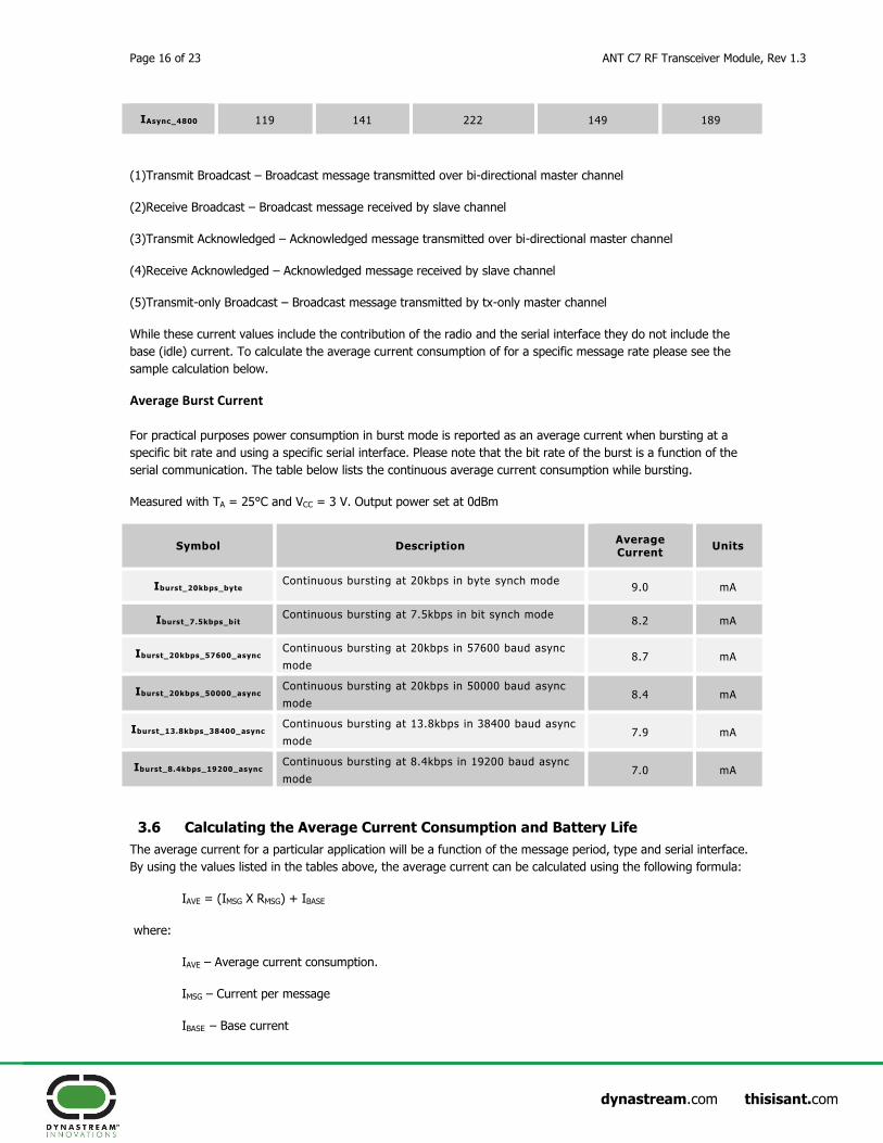
IAsync_4800 119 141 222 149 189
(1)Transmit Broadcast – Broadcast message transmitted over bi-directional master channel
(2)Receive Broadcast – Broadcast message received by slave channel
(3)Transmit Acknowledged – Acknowledged message transmitted over bi-directional master channel
(4)Receive Acknowledged – Acknowledged message received by slave channel
(5)Transmit-only Broadcast – Broadcast message transmitted by tx-only master channel
While these current values include the contribution of the radio and the serial interface they do not include the
base (idle) current. To calculate the average current consumption of for a specific message rate please see the
sample calculation below.
Average Burst Current
For practical purposes power consumption in burst mode is reported as an average current when bursting at a
specific bit rate and using a specific serial interface. Please note that the bit rate of the burst is a function of the
serial communication. The table below lists the continuous average current consumption while bursting.
Measured with TA = 25°C and VCC = 3 V. Output power set at 0dBm
Symbol Description Average Current
Units
Iburst_20kbps_byte Continuous bursting at 20kbps in byte synch mode
9.0 mA
Iburst_7.5kbps_bit Continuous bursting at 7.5kbps in bit synch mode
8.2 mA
Iburst_20kbps_57600_async Continuous bursting at 20kbps in 57600 baud async
mode 8.7 mA
Iburst_20kbps_50000_async Continuous bursting at 20kbps in 50000 baud async
mode 8.4 mA
Iburst_13.8kbps_38400_async Continuous bursting at 13.8kbps in 38400 baud async
mode 7.9 mA
Iburst_8.4kbps_19200_async Continuous bursting at 8.4kbps in 19200 baud async
mode 7.0 mA
3.6 Calculating the Average Current Consumption and Battery Life
The average current for a particular application will be a function of the message period, type and serial interface.
By using the values listed in the tables above, the average current can be calculated using the following formula:
IAVE = (IMSG X RMSG) + IBASE
where:
IAVE – Average current consumption.
IMSG – Current per message
IBASE – Base current

ANT C7 RF Transceiver Module, Rev 1.3 Page 17 of 23
dynastream.com thisisant.com
For example, given an ANT node that transmits broadcast data over a bi-directional channel at 0.5Hz using a byte
synchronous serial interface, the continuous average current can be calculated as follows:
IAVE = (49 X 0.5) + 1.0 = 25.5µA
To calculate the expected battery life of a system, the battery capacity and usage model must also be considered.
The following formula can be used (please note that this considers the current consumed by the ANT part of the
system only):
TBAT =CBAT
(TActive∙ IAve) + (TIdle∙IIdle)
where:
TBAT – Expected battery life of the system
CBAT – Battery capacity
TActive – Active time in transmit mode in a day
IAve – Average current consumption in active mode
TIdle – Time in non-active mode (off) in a day
IIdle – Average current in idle mode
For example, for a system using a CR2032 coin cell batter transmitting at 0.5Hz broadcast for 1 hour per day, the
battery life of the system can be calculated as follows:
TBAT =220mAh
(1h∙ 25.5μA)+(23h∙0.5μA)= 5945.95 days = 16.3 years
Please note that the above example assumes that 100% of the battery capacity can be dedicated to the ANT
portion of the system.
An online power consumption estimator is provided at http://www.thisisant.com/calculator

Page 18 of 23 ANT C7 RF Transceiver Module, Rev 1.3
dynastream.com thisisant.com
4. Mechanical Drawings

ANT C7 RF Transceiver Module, Rev 1.3 Page 19 of 23
dynastream.com thisisant.com

Page 20 of 23 ANT C7 RF Transceiver Module, Rev 1.3
dynastream.com thisisant.com

ANT C7 RF Transceiver Module, Rev 1.3 Page 21 of 23
dynastream.com thisisant.com

Page 22 of 23 ANT C7 RF Transceiver Module, Rev 1.3
dynastream.com thisisant.com

ANT C7 RF Transceiver Module, Rev 1.3 Page 23 of 23
dynastream.com thisisant.com
5. Technical Support
The C7 module takes the reference design of CC2571 from Texas Instruments. Users can seek technical support,
esp. about hardware, from Texas Instruments, www.ti.com. Users can also seek application support from
Dynastream Innovations, www.thisisant.com.
5.1 ANT Forum
Users are encouraged to participate in the ANT forum moderated by the application engineering team of
Dynastream Innovations for any engineering discussions. Joining the ANT forum is free and open at
http://www.thisisant.com/forum.
5.2 Public Technical References
Documents:
1. CC2570/CC2571 Datasheet, Texas Instruments 2. ANT Message Protocol and Usage, Dynastream Innovations 3. Integrated ANT-FS Interface Control Document 4. Interfacing with ANT General Purpose Chipsets and Modules, Dynastream Innovations
Software:
6. ANTwareII – a system testing and debugging tool
The above documents are available at http://dynastream.com/developer/c7-modules. More resources can be
found at http://www.thisisant.com/developer/resources/downloads.
5.3 ANT Developer’s Zone
ANT development software tools, application notes, reference designs and other public resources are found in the
ANT developer’s zone at http://www.thisisant.com/developer.
To begin development with the ANT+ interoperability, please become an ANT+ Adopter or ANT+ Alliance member
to obtain the access to the ANT+ Adopter Zone. ANT+ documents and design tools contained in the ANT+
Adopter zone include the ANT+ Device Profiles, ANT-FS specification, ANT software (PC/Mac) libraries with source
code, and embedded reference designs with source code.
5.4 ANT Social Media
ANT is on the following social media,
YouTube: http://www.youtube.com/user/ANTAlliance
Twitter: http://twitter.com/ANTPlus
Facebook: https://www.facebook.com/pages/ANT/145243832297767
LinkedIn: http://www.linkedin.com/groups?gid=1379137


![TTIEA][T - The Ant – The Ant](https://img.dokumen.tips/doc/110x75/6293513c64ae355c021c5d95/ttieat-the-ant-the-ant.jpg)