Embed Size (px)
DESCRIPTION
hf
Citation preview

Model 760B Tapping Machines can be either airor hydraulically operated andare used for makingpipe and tank taps from 3" to 16" (DN 80 to DN400). Its maxiumum working pressure is 1,480 psi(100 bar) at 100°F (38°C). Its operatingtemperature is -20°F (-29°C) to 700°F (371°C) at700 psi (48 bar) for intermittent service. Itsmaximum continuous rating is 350°F (177°C) at1,025 psi (48 bar).
This model features a split frame for lowermaintenance costs and ease of packingreplacement.
The basic machine includes:
Lower-in crank
Measuring rod
Retainer rod pusher
Ring gasket
Bleeder valve and nipple
Motor adapter
Set of bolts and nuts
LOCK-O-RING® bypass gauge
T. D. Williamson, Inc., is committed to providingyou with the exact product to assist you inplanning, budgeting and meeting the specificationsfor your individual application needs. Thefollowing options are available:
Model 760B Tapping Machine can be either air or hydraulically operated.
* For design code options not listed and additional sizes,consult your sales representative.
760 Tapping MachineSizes: 3” through 16”
Description
Features
Options*
T. D. Williamson, Inc.
TDW
Model 760B
Tapping machines are used for makingconnections to pipelines, tanks, and plantpiping without shutdown and are used tomake hot taps in preparation for pluggingmachine application.
T.D. Williamson, Inc. P.O. Box 3409 Tulsa, Oklahoma 74101-3409 918-447-5100 Fax: 918-446-6327 www.tdwilliamson.comData subject to change without notice. / Dimensions not for construction unless certified. / ® Registered trademark of T.D. Williamson, Inc. in the United States and foreign countries / TM Registered trademark of T.D. Williamson, Inc. in the United States and foreign countries / © Copyright 1997. All rights reserved T.D. Williamson, Inc. / Printed in USA
Toll Free
1-888-TDWmSon (839-6766)
Patented in the United States and in foreign countries.ISO 9001 Certified
760 Tapping Machine
Typical Tapping Setup
Boring Bar
AdapterCutter Holder
Cutter
Gasket
SANDWICH®
Valve
Gasket
Pipeline
STOPPLE® Fittingor Tapping Fitting
Split Frame
Pilot
Bulletin No: 1000.006.00Date: February 1999Cross Indexing No: n/aSupersedes: 404 (9/1/89)

Dimensions and Part Numbers
760 Tapping MachineT. D. Williamson, Inc.
Hydraulic Operation Model
Boring Bar Travel 66" (1,676 mm)Tank Taps* 3" through 14" (80-350 mm)Pipe Taps* 3" through 16" (80-400 mm)Max. Operating Pressure 1,480 psi (100 bar) at 100°F (38°C)Max. Operating Temperature 700°F (371°C) at 700 psi (48 bar)**Power Hydraulic or Air MotorFeed Rate Standard .005" (.127 mm) per revolution/optional .003" (.076 mm) per revolutionLower-In Crank 4-1/2 turns per inch (5.6 mm per turn)Length without measuring rod 88-1/2" (2,248 mm)Length with measuring rod 158-1/2" (4,026 mm)Meets NACE specification MR0175-93
* See note 5 in "Recommended Power Options" Chart.** For intermittent service only. Its maximum continuous rating is 350°F (177°C) at 1,025 psi (48 bar).
Standard Feed (.005"/Revolution) Slow Feed (.003"/Revolution) Lbs. Kg. Part Number Part Number
Tapping Machine 500 227 05-2180-0000 05-2178-0000Air Motor Drive Assembly 40 18 05-2326-0000 05-2326-0000Skid* 212 96 05-0040-0000 05-0040-0000TOTAL WEIGHT 752 341* If skid is not purchased with the tapping machine, there will be a special crating charge; consult factory.
TDW
Standard Feed (.005"/Revolution) Slow Feed (.003"/Revolution) Lbs. Kg. Part Number Part Number
Tapping Machine 500 227 05-2180-0000 05-2178-0000Single Drive Unit & Control Valve 45 20 05-0006-0000 05-0006-0000Dual Drive Unit & Control Valve 100 45 05-0930-0000 05-0930-0000Skid* 212 96 05-0040-0000 05-0040-0000Power UnitHydraulic Power Unit and 50' Hose w/Oil
Manual Start/Diesel 585 266 05-2017-0000 05-2017-0000Electric Start/Diesel 600 272 05-2330-0000 05-2330-0000Manual Start/Gas 533 242 05-2351-0000 05-2351-0000Electric Start/Gas 550 250 05-2354-0000 05-2354-0000
* If skid is not purchased with the tapping machine, there will be a special crating charge; consult factory
Operating Specifications
Air Operation Model
Model 760B
T.D. Williamson, Inc. P.O. Box 3409 Tulsa, Oklahoma 74101-3409 918-447-5100 Fax: 918-446-6327 www.tdwilliamson.comData subject to change without notice. / Dimensions not for construction unless certified. / ® Registered trademark of T.D. Williamson, Inc. in the United States and foreign countries / TM Registered trademark of T.D. Williamson, Inc. in the United States and foreign countries / © Copyright 1997. All rights reserved T.D. Williamson, Inc. / Printed in USA
Diesel Power UnitGasoline Power Unit
Dimensions and Part Numbers
760 Tapping MachineT. D. Williamson, Inc.
TDW
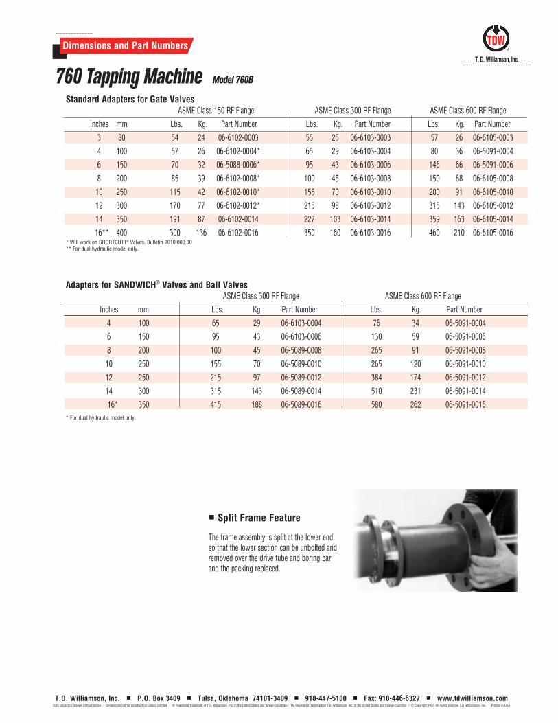
Standard Adapters for Gate ValvesASME Class 150 RF Flange ASME Class 300 RF Flange ASME Class 600 RF Flange
Inches mm Lbs. Kg. Part Number Lbs. Kg. Part Number Lbs. Kg. Part Number
3 80 54 24 06-6102-0003 55 25 06-6103-0003 57 26 06-6105-0003
4 100 57 26 06-6102-0004* 65 29 06-6103-0004 80 36 06-5091-0004
6 150 70 32 06-5088-0006* 95 43 06-6103-0006 146 66 06-5091-0006
8 200 85 39 06-6102-0008* 100 45 06-6103-0008 150 68 06-6105-0008
10 250 115 42 06-6102-0010* 155 70 06-6103-0010 200 91 06-6105-0010
12 300 170 77 06-6102-0012* 215 98 06-6103-0012 315 143 06-6105-0012
14 350 191 87 06-6102-0014 227 103 06-6103-0014 359 163 06-6105-0014
16** 400 300 136 06-6102-0016 350 160 06-6103-0016 460 210 06-6105-0016* Will work on SHORTCUTT® Valves, Bulletin 2010.000.00 ** For dual hydraulic model only.
Adapters for SANDWICH® Valves and Ball ValvesASME Class 300 RF Flange ASME Class 600 RF Flange
Inches mm Lbs. Kg. Part Number Lbs. Kg. Part Number
4 100 65 29 06-6103-0004 76 34 06-5091-0004
6 150 95 43 06-6103-0006 130 59 06-5091-0006
8 200 100 45 06-5089-0008 265 91 06-5091-0008
10 250 155 70 06-5089-0010 265 120 06-5091-0010
12 250 215 97 06-5089-0012 384 174 06-5091-0012
14 300 315 143 06-5089-0014 510 231 06-5091-0014
16* 350 415 188 06-5089-0016 580 262 06-5091-0016* For dual hydraulic model only.
Model 760B
T.D. Williamson, Inc. P.O. Box 3409 Tulsa, Oklahoma 74101-3409 918-447-5100 Fax: 918-446-6327 www.tdwilliamson.comData subject to change without notice. / Dimensions not for construction unless certified. / ® Registered trademark of T.D. Williamson, Inc. in the United States and foreign countries / TM Registered trademark of T.D. Williamson, Inc. in the United States and foreign countries / © Copyright 1997. All rights reserved T.D. Williamson, Inc. / Printed in USA
Split Frame Feature
The frame assembly is split at the lower end,so that the lower section can be unbolted andremoved over the drive tube and boring barand the packing replaced.

Dimensions and Part Numbers
760 Tapping MachineT. D. Williamson, Inc.
TDW
Model 760B
Cutter Holders LOCK-O-RING® Plug Holders
Inches mm Lbs. Kg. Part Number Lbs. Kg. Part Number
3 & 4 80 & 100 2.5 1 05-0054-0001 -- -- --
6-12 150-300 8 4 05-0054-0002 -- -- --
14-16 350-400 7 3 05-0054-0003 -- -- --
4-16 100-400 -- -- -- 3.5 2 05-0075-0000
Cutter Holders & LOCK-O-RING® Plug Holders
Nominal Tap Size Actual Size Cutters Pilot Drills Spare U-rods
Inches mm Inches mm Wt./Lbs. Wt./Kg. Part Number Wt./Lbs. Wt./Kg. Part Number Part Number
4 100 3-7/16 87.3 2 0.9 05-0328-0004 1/2 0.2 05-0293-0008 00-1424-0012
6 150 5-15/32 138.9 5-3/4 3 05-0328-0006 2 0.9 05-0293-0002 00-1424-0003
8 200 7-5/16 185.8 14-1/2 7 05-0328-0008 2 0.9 05-0293-0003 00-1424-0003
10 250 9-1/2 241.3 22-1/2 10 05-0328-0010 2 0.9 05-0293-0004 00-1424-0003
12 300 11-1/2 292.1 36 16 05-0328-0012 2-1/2 1.0 05-0293-0005 00-1424-0008
14 350 12-3/4 323.9 42 19 05-0389-0014 5-1/2 2.5 05-0293-0006 00-1424-0008
16 400 14-5/8 371.5 61 28 05-0389-0016 6 2.7 05-0293-0007 00-1424-0008
4 100 3-7/8 98.4 3-1/4 1 05-0330-0004 1/2 0.2 05-0293-0008 00-1424-0012
6 150 5-7/8 149.2 8-3/4 3 05-0330-0006 2 0.9 05-0293-0002 00-1424-0003
8 200 7-3/4 196.9 20 9 05-0330-0008 2 0.9 05-0293-0003 00-1424-0003
10 250 9-3/4 247.7 23 10 05-0330-0010 2 0.9 05-0293-0004 00-1424-0003
12 300 11-3/4 298.5 40 18 05-0330-0012 2-1/2 1.0 05-0293-0005 00-1424-0003
4 100 3-15/16 100 3-1/2 2 05-0329-0004 1/2 0.2 05-0293-0008 00-1424-0012
6 150 5-15/16 150.8 9 4 05-0329-0006 2 0.9 05-0293-0002 00-1424-0003
8 200 7-7/8 200 16 7 05-0329-0008 2 0.9 05-0293-0003 00-1424-0003
10 250 9-7/8 200.8 27 12 05-0329-0010 2 0.9 05-0293-0004 00-1424-0003
12 300 11-13/16 300.1 40-1/2 18 05-0329-0012 2-1/2 1 05-0293-0005 00-1424-0008
14 350 13-1/16 331.8 49 22 05-0388-0014 5-1/2 2.5 05-0293-0006 00-1424-0008
16 400 15-1/16 382.6 64 29 05-0388-0016 6 2.7 05-0293-0007 00-1424-0008
STOPPLE® Cutters & Pilot Drills
SHORTSTOPP® Cutters & Pilot Drills
Standard Cutters & Pilot Drills
T.D. Williamson, Inc. P.O. Box 3409 Tulsa, Oklahoma 74101-3409 918-447-5100 Fax: 918-446-6327 www.tdwilliamson.comData subject to change without notice. / Dimensions not for construction unless certified. / ® Registered trademark of T.D. Williamson, Inc. in the United States and foreign countries / TM Registered trademark of T.D. Williamson, Inc. in the United States and foreign countries / © Copyright 1997. All rights reserved T.D. Williamson, Inc. / Printed in USA
Dimensions and Part Numbers
760 Tapping MachineT. D. Williamson, Inc.
TDW
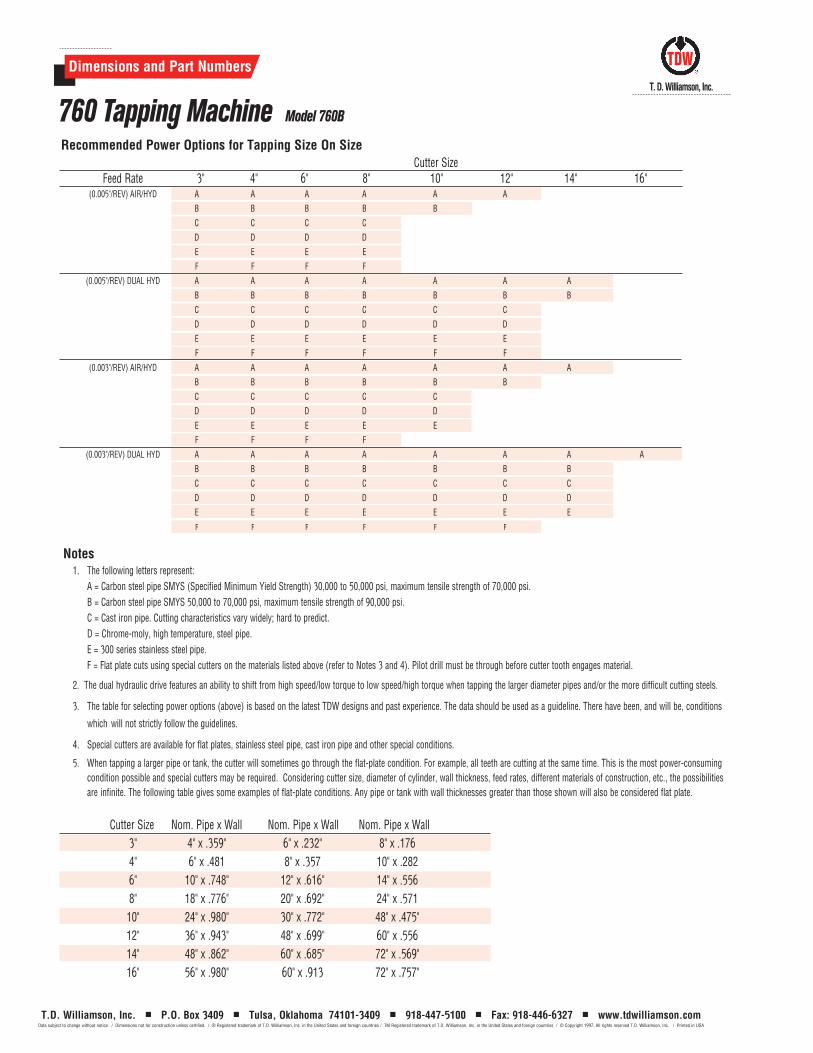
Recommended Power Options for Tapping Size On SizeCutter Size
Feed Rate 3" 4" 6" 8" 10" 12" 14" 16"(0.005"/REV) AIR/HYD A A A A A A
B B B B B
C C C C
D D D D
E E E E
F F F F
(0.005"/REV) DUAL HYD A A A A A A A
B B B B B B B
C C C C C C
D D D D D D
E E E E E E
F F F F F F
(0.003"/REV) AIR/HYD A A A A A A A
B B B B B B
C C C C C
D D D D D
E E E E E
F F F F
(0.003"/REV) DUAL HYD A A A A A A A A
B B B B B B B
C C C C C C C
D D D D D D D
E E E E E E E
F F F F F F
Notes1. The following letters represent:
A = Carbon steel pipe SMYS (Specified Minimum Yield Strength) 30,000 to 50,000 psi, maximum tensile strength of 70,000 psi.B = Carbon steel pipe SMYS 50,000 to 70,000 psi, maximum tensile strength of 90,000 psi.C = Cast iron pipe. Cutting characteristics vary widely; hard to predict.D = Chrome-moly, high temperature, steel pipe.E = 300 series stainless steel pipe.F = Flat plate cuts using special cutters on the materials listed above (refer to Notes 3 and 4). Pilot drill must be through before cutter tooth engages material.
2. The dual hydraulic drive features an ability to shift from high speed/low torque to low speed/high torque when tapping the larger diameter pipes and/or the more difficult cutting steels.
3. The table for selecting power options (above) is based on the latest TDW designs and past experience. The data should be used as a guideline. There have been, and will be, conditions
which will not strictly follow the guidelines.
4. Special cutters are available for flat plates, stainless steel pipe, cast iron pipe and other special conditions.
5. When tapping a larger pipe or tank, the cutter will sometimes go through the flat-plate condition. For example, all teeth are cutting at the same time. This is the most power-consuming condition possible and special cutters may be required. Considering cutter size, diameter of cylinder, wall thickness, feed rates, different materials of construction, etc., the possibilities are infinite. The following table gives some examples of flat-plate conditions. Any pipe or tank with wall thicknesses greater than those shown will also be considered flat plate.
Cutter Size Nom. Pipe x Wall Nom. Pipe x Wall Nom. Pipe x Wall3" 4" x .359" 6" x .232" 8" x .1764" 6" x .481 8" x .357 10" x .2826" 10" x .748" 12" x .616" 14" x .5568" 18" x .776" 20" x .692" 24" x .571
10" 24" x .980" 30" x .772" 48" x .475"12" 36" x .943" 48" x .699" 60" x .55614" 48" x .862" 60" x .685" 72" x .569"16" 56" x .980" 60" x .913 72" x .757"
Model 760B
T.D. Williamson, Inc. P.O. Box 3409 Tulsa, Oklahoma 74101-3409 918-447-5100 Fax: 918-446-6327 www.tdwilliamson.comData subject to change without notice. / Dimensions not for construction unless certified. / ® Registered trademark of T.D. Williamson, Inc. in the United States and foreign countries / TM Registered trademark of T.D. Williamson, Inc. in the United States and foreign countries / © Copyright 1997. All rights reserved T.D. Williamson, Inc. / Printed in USA