Embed Size (px)
Citation preview

ISSN 0970.3993
70February1989 CNDIA Rs. 8.00
eectonicoTHE MAGAZINE FOR PROFESSIONALS
HIGH DENSITY
TV
COMMAND A COMPUTER
CONSTRUCT A HOUSE
PRACTICAL FILTER
DESIGN (1)
! SOFTWARE
WITHOUT TEARS
OVERVOLTAGE
PROTECTION
THIRD GENERATION
CD PLAYERS
DEVELOPMENT SYSTEM
FOR M6805
LCD
1.11 TER

Publisher: C.R. ChandarenaEditor: Surendra lyerTechnical Adviser : Ashok DongreCirculation: Advertising: J. OnesProduction: C.N. %Mooed
Address:ELEKTOR ELECTRONICS PVT. LTD.52, C Proctor Road, Bombay -400 MP INDIATelex:10111 76661 ELEK IN
Overseas editions:
Printed at : Tropti OffsetBombay - 400 013
15,1-.1;4,343,2,5t1,4B,291
ONTENTS
Editorial
Gallium -arsenide a bright future? .....
Special Feature
High density television a costly dream come true .
Command a computer construct a house ............
Audio & Hi-fi
Decoding ICs for CD players .
Components
Practical filter design: a new series ......
Computers
PROJECT: Autonomous I/O controller (final part
A low cost development system for M6805
General Interest
Overvoltage protection .....
PROJECT: Thyristor speed control ..........
Improving automotive wiring systems .
PROJECT: LCD luxmeter
Science & Technology
Software without tears ..........
Test & Measurement
REVIEW: Part 13 - Power supplies 111 ...........
Information
Industry news .......
Telecom news[rooms ne
New Products
Appointments .......
Guidelines
Index of advertisers
Volume 7 Number 2
February 1989
/23
2.10
2.14
2.45
2.34
/39
2.47
2.54
. 2.18

----(4344
Front coverthe Oiympus thermalmodel In the satelliteassembly hall of BritishAerospace. Olympus 1,the world's largest andmost powerful civilthree -axis stabilizedtelecommunicationsatellite has alreadycompleted solarsimulation tests and isnow undergoing firqlenvironmental restingprior to launch onArian III in a fewmonths' timeOlympus 1 Is 2.9 mwide, 5.6 m long, andhas a solar array ofover 25.6 m2. It hasbeen built under con-tract to the EuropeanSpace Agency. It car-ries a 20-30GfizPoYload, suitable forvideo teleconferencingand other business ap-plications.
GALLIUM -ARSENIDE:A BRIGHT FUTURE?Mainly because of the needs of the satellite TV business, but also those of theautomobile industry, Me demand for galliumarsenide (GaAs) devices is grow-ing at a rate not foreseen by many only a year or so ago. Pundits now reckonthat the world market for GaAs devices will be worth in excess of £2 billion by1992. The main requirements will be for monolithic microwave integrated cir-cuits (MMIGs), field-effect transistors (FETs), and high electron -mobility transistors(HEMTs).
Gallium -arsenide devices have some important advantages over silicondevices First, they exhibit far greater electron mobility, which means that con-siderably faster circuits can be realized than with silicon. Second. they havetar better thermal stability and greater resistance to radiation. which is of par-ticular importance for the production of very fast and highly Integratedmemories
On the other hand, silicon has better uniformity, purity, and surfacesmoothness, which results in better control, and thus greater efficiency.
As far as the state.of.the-art Is concerned, much larger and more complex IC,can at present be fabricated with silicon. In general, gallium -arsenide tech-nology is still well behind silicon technology, but the industry expects that itwill have caught up by the early to mid 19905
From this, It Is clear that the applications for GaAs devices will remain, at leastfor the time being, in those areas where the physical properties of GaAs aresuperior to those of silicon. These areas include the military sphere aerospaceindustry, aviation, satellite television, and automotive engineering. Initially, theuse of gallium -arsenide will be confined to small and medium scale IC's, butin Me not too distant future It will also be possible to use the material for VLSIcircuits.
The United Kingdom, through Plessey, hos a good lead In Europe in GaAstechnology-in fact, there is no other European supplier. But competition fromJapan and the USA is strong. Such an Important lead is of course worthpreserving and it is therefore, encouraging that the Government has recentlyauthorized a US million GaAs research programme
There are, however, quite a few opponents to the GaAs research programmewho say that this money would be better spent on research into silicon tech-nology Indeed, a number of these researchers believe that within a relativelyshort time silicon circuits will have been developed for speeds up to 25 GHz.Not unnaturally, many industry insiders take a very sceptical view of thesebeliefs.
The government programme for GaAs research has staunch supporters.among them the chairman of BICC, Sir William Barlow. During a recent lectureat the Institute of Electrical Engineers, Sir William called for a vast fibre -opticcable network across the UK for the distribution of satellite TV and data ser-vices Such a scheme would provide a massive demand for GaAs devices foruse in the necessary decoders and allied equipment. It would also createmany thousands of jobs over a long period. Alas, it is only a plan that willprobably never come to fruition owing to the absence of firm, co-ordinatedpolicies

OVER -VOLTAGE PROTECTION
The use of some form of over -voltage protection in electronicequipment is often not contemplated until a huge voltage surgehas caused considerable damage. Since it is invariably better to
be safe than sorry, this article looks at two over -voltage protectiondevices (surge arresters), the varistor and the gas -filled conductor,
and discusses their operation and application.
Over -voltage is basically any voltage thatexceeds the nominal value plus the statedtolerance. Over -voltage can be generatedby various sources, of which lightning isprobably the best known. Athunderstorm, even while it is severalmiles away, can give rise to voltage peaksof considerable amplitude on the mainsnetwork. The switching on and off ofrelatively heavy loads connected to longwires or conductors, which form a con-siderable self-inductance, also causessuch peaks. The mains network is, how-ever, not the only large self-inductancewhere over -voltage protection is re-quired: model railway systems, telephoneand computer networks are also prone topicking up interference and surges with adisastrous effect.A number of components are availablefor over -voltage protection. In electroniccircts, much use is made of conven-tionauil diodes, suppressor diodes andzener diodes. The varistor is an in-teresting component that has alreadybeen usesI in. a number of projects re-cently featured in Elektor India.Figure I shows a comparison betweenthe 4 most commonly used types of over- Fig. I. This charts ows maximum peak c 1.20 pM as 0 function of conductionvoltage protection device, in respect of voltage for four type of over -voltage protectionurrent as ice.
wa=
2.24 mater. India Fete, 1989

0.1 mA when the varistor does not con-duct. In the rounded part at the low sideof the curve, the internal resistance ismainly determined by Re which ismuch smaller than Az, but gill largerthan Rs. At large currents, the resist-ance of the ideal varistor is practicallynought. The ohmic resistance of themetal -oxide parts (Re) then determinesthe internal resistance. Capacitor C isrelatively large (100 to 4000 pF). With-out additional components, such as
diode-connected variable capacitances, ristors are, therefore, un-
suitable for high -frequency applications.Related to over -voltage protection, how-ever, the internal capacitance is usefulbecause it provides some smoothing ofvoltage surges. Inductor L representsmainly the self-inductance of thevaristor's wires. For optimum speed ofthe varistor, these wires should be keptas short as possible.At less co nominal voltages, ammonsuitable varistor may be made fromseries-cnected varistors individivallyspecifiedon for a lower nominal voltage.When this is done, care.should be takento use varistors from the same series.Parallel connection of varistors is notpossible owing to tolerance on the effec-tive surface area. In the worst case, thistolerance may cause currents M parallel-conected varistors to differ by as muchas a factor 1,000. Selecting matchedtypes is particularly difficult for highpeak currents, since measuring andgenerating these require specializedequipment.
The electrical behaviour of a varistor inoverload conditions depends on the typeof overload. A too high peak currentcauses the varistor to explode, so that theconnection is broken. A long-term,light, overload gives rise to mixing of themetal -oxide granules, so that the varistorchanges gradually into a low -value re-sistor.Evidently, there exist no maximumvalues for voltage and current surges, sothat a correctly selected varistor may stillbe overloaded. With this M mind, it isclear why varistors are typicallymounted at some distance from othercomponents, especially when used forsuppression of interference on low -impedance networks, such as the mains.
Which varistor?In general, the choice of varistor for aparticular application is made on thebasis of the datasheets supplied by themanufacturer. First, the operatingvoltage is determined, taking care not toconfuse the DC and AC specifications.Next, the tolerance is added to thenominal voltage, and the result is
rounded off to the next higher value inthe series. For most applications with240 V and 220 V mains networks, a
Fig. 6. Current/voltage response of a noble -gas filled surge arrester toe sinusoidal voltage
250 V varistor is adequate. Maximumpeak current and energy absorbtion arehen determined, and a suitable type iselected. The U -I characteristic of thearistor shows the maximum voltage
across the varistor when this conducts. Ifhis voltage is higher than the maximum
permissible voltage for the protected cir-uit, a different varistor with a more ap-
propriate U -I charcteristic will have to befound.
Noble -gas filled surge arrestersThis type of over -voltage protectiondevice is based on the gas discharge prin-ciple, as illustrated in Fig. 6. Once thesinusoidal voltage has reached the dis-charge level, Us, a glow discharge takesplace that brings the voltage down to 70to 150 V. Current is then 0.1 A to 1.5 A.If the current rises, an arc dischargetakes place that brings the voltage down
I
Fig. 8. Conduction vollag6 V, of a nobleFig. 0. reassess specter, or a noble -gas gas filled surge arrester as a Nairn °. of thfilled surge arrester. rate of rise do/dr, of the over -voltage pulse.

Fig. 2. Symmetrical U -I characteristic of a varistor.
conduction voltage and maximum peakcurrent during conduction. This articlemainly focuses on varistors and gas -filled surge arresters.
Conducting ceramicsThe varistor, also called VDR (voltage -dependent resistor), is comparable, tosome extent, to the zener diode. The dif-ference is mainly that the U -I character-istic of the varistor is symmetrical, i.e.,the zener effect occurs with positive aswell as negative current. The curve inFig. 2 is obtained from
I=KU.
or
U=CP
whereI = current through varistorU =voltage across varistorK; C = a constant dependent on size ofvaristor element; K=-a; 6 = material constants; a=1/0.
Both constants, a and K (or (3 and C),are taken from the manufacturer's datasheets. Depending on the applicationrange, additional data is provided.Among these is the maximum peak cur-rent, The graph in Fig. 3 shows aso-called 8/20 ps current surge, which isused by a number of manufacturers forspecifying the electrical characteristicsof their varistors. Even for smallvaristors, the value, of Inm is expressedin kilo -amperes (kA).
The disc -shaped ceramic element in avaristor is typically made from a metal -2.26 New, Te9
Fig. 3. Shape definition of the .4:ailed8/20 surge used for measuring the maximumpeak current capability of over -voltage pro-tection devices. The repeal rate of this pulseis 30 seconds or 3 minutes, depending on thetest method adopted.
IIP 4irab 11) ieko,04.QQ
1, mlerovarislorsmeept: :ill e
arIL...
Fig. 4. Basic structure of the ceramic material used in a varistor.
oxide powder - usually zinc -oxide(ZnO), titanium -oxide (TiO) or silicon -carbide (SiC). The simplified internalstructure of the ceramic element isshown in Fig. 4. Am icro-varistor iscreated where granules touch. Theseparation layer forms a high resistance,causing current to flow through the ox-ide granules and the micro-varistors.This fact makes it possible to set up afew rules of thumb for the design anduse of varistors. Doubling the thicknessof the ceramic plate will result in adoubled breakdown voltage, since thenumber of micro-varistors in series isthen doubled. Similary, doubling of thesurface area results in a higher maximum-peak current since the number of currentpaths arranged in parallel is doubled.Lastly, doubting the volume results indouble the amount of energy that can beabsorbed.
The equivalent circuit of a varistor isdrawn in Fig. 5: Rv is an ideal varistor.Rz causes a leakage current of less than
Fig. 5. Equivalent circuit a a varistor.

to 10 to 20 V. As the current becomessmaller, the arc will extinguish at 10 to100 mA. After a short glow Plats, thesurge arrester reverts to its normal state.Combination of the voltage and currentcurves yields the U -I characteristicshown in Fig. 6c. It is seen that thevoltage across the conductor decreasesrapidly when ignition occurs. This is incontrast to the varistor, which maintainsa largely constant voltage.The internal structure of the noble -gasfilled surge arrester is illustrated inFig. 7. The device is hermetically sealedto prevent ambient parameters, such asgas type, gas pressure, relative humidityand pollution, from changing its care-fully defined electrical characteristics.The electrodes are covered in a materialthat facilitates electron emission. A fir-ing aid may be mounted at the inside ofthe insulator to speed up reaction time.The electrical characteristics of thenoble -gas filled surge arrester are deter-mined mainly by the type of gas, gaspressure, and electrode activationmaterial.Figure 8 shows that the dischargevoltage rises if the rate of rise of the in-terferering voltage exceeds a certainvalue. As already seen in Fig. 6, thenoble -gas fined surge arrester is not ex-tinguished until the instantaneousvoltage falls below the quench voltage,Us. This is not a problem with alter-nating voltages, but direct voltageshigher than the quench voltage may giverise to difficulties. Everything is fine aslong as the the internal resistance of thevoltage source is so high as to cause thevoltage at the relevant current to dropbelow the quench voltage. A problemarises, however, if the internal resistanceof the voltage source is so low that thesurge arrester is not quenched. For-tunately, quenching can still be ensuredby connecting a varistor in series withthe gas -filled surge arrester as shown inFig. 9. Since, after the interfering pulse
has disappeared, the voltage across thevaristor remains fairly constant, thevoltage across the conductor is sure tofall below the quench level. Further ap-plications of this series circuit arisewhere low capacitance (I to 10 pF) aswell as high resistance (>1010 521 are re-quired, but where voltage dips down tothe arc level are just as harmful as over -voltage surges. Following the dischargingof )he gas -filled surge arrester, theraristor ensures that the voltage remainswithin safe limits (see Fig. 96).
Over -voltage protection inpracticeAs en example of a practical application,Fig. 10 shows how a varistor can preventover -voltage damaging, say, a computer.In practice, it will be found that fittingsmall varistors in all available equipmentgives better results than a single, high-energy, varistor fitted at a central lo-cation across the mains lines. Thevaristor type given in Fig. 10 is conser-vatively rated because the degree andnature of the interference are hard topredict. In general, the choice of asuitable varistor is not critical in protec-tion circuits for low -power equipment- in this case, the nominal voltage isthe main criterions.Provided there is room to fit them,varistors may also be used to prevent arc-ing on the collector of small DC motors- see Fig. II. For AC as well as DCmodel railway systems, it is rec-ommended to use varistors on motorsand track sections.
Source:
Gas -filled over -voltage conductors,metal -oxide varistors (SIOV). SiemensPublication.
Fig. 10. Typical sorban application.
Fig. tr. Arcing at the collector of n DCmotor can he prevented by fitting threevaristors on the rotor.
Component availability note:
A range of Siemens SIOV varistors, includingthe Type 51014250 used in recent ElektorElectronics projects, is available from Eke-troValue Limited 28 St dudes Road Englefield Green Egham Surrey TW20OHB. Telephone: (0784) 33603. Telex: 264475.Fax: (0784) 35216. Northern branch: 680Burnage Lane Manchester M19 INA. Tele-phone: (061 432) 4945.
Fig. 9. Series connection of a noble.ga On Siemens's range of worn, S steads for disc -type fit = block type); the following twofilled surge arrester and a metaboxid digit number indicates the diameter of the varistor element; K Indicates a tolerance of 109veristor. The graph shows the voltage acros (3=5o: S = special): the last number indiotes SIOV (Siemens metalOxide Varistor
the combination. is a registered trademark.
ottor was mews, nes 2.27
DECODING ICs FORCD PLAYERS
Although the majority of popular compact -disc players on themarket offer 16-bitx4 times oversampling, it is by no means
certain that this is the standard for the future. Philips-Valvo haveintroduced new decoding chips that may herald the third gener-ation compact -disc player offering 1-bitx256 times oversampling.
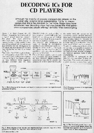
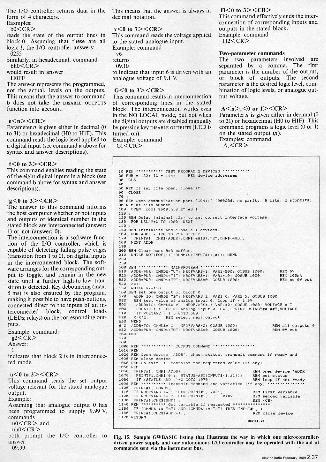
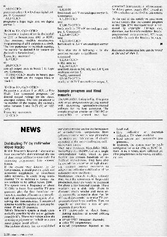
Figure 1 of Pitch Control for CDPlayers. showed the block schematic ofa typical second -generation compact -disc player. The signal processing(decoding) section of that diagram isrepeated M Fig. 1 of this article. It con-sists of four special CD ICs and a stan-dard DRAM. For the third -generationCD player, the four special CD ICs havebeen replaced by two new ICs as shownin Fig. 2.The current SAA7220 is a phase linear,4x oversampling digital filter with 120filter coefficients. Its frequency responseis shown in Fig. 3. In conjunction withthe Type TDA1541 16 -bit digital -to -analogue converter and the Type
TDA1542 third -order analogue filter, ithas a ripple of only 0.02 dB in the passband and an attenuation of >50 dBoutside the pass -band. It is not ideal foruse with de -emphasis circuits.The SAA7220 also interpolates thevalues of missing or uncorrectablesamples. It can estimate up to eight suchsamples as shown in fig. 4. The figurealso shows that the SAA7210 decoderprovides a basic interpolation functionprior to the SAA7220.For good sound quality, both efficienterror correction and good linearity ofthe Type TDA1541 digital -to -analogueconverter are vital. This IC contains twocomplete I6 -bit D -A converters that, like
the earlier TDAI540, operate on thewell-known current division principle.Since each of the stereo channels has itsown converter, there is no time delay be-tween their signals. The conversion timeis shorter than 2 ps, so that data rates ofmore than 6 Mbit s can be processed.By periodic overlapping of the two D -Ason one chip, it is possible to achieve asampling rate of 380 kHz per channel.As a matter of fact, in some CD players -
the TDA1541 provides 16 -bit 0 8 timesoversampling.The SAA7220 is connected to theTDAI541 via a so-called FS (Inter -IC -Sound) bus. This consists of a clock line,a serial data line, a control line, and a
Fig. 1. of the decoder and digital -to -analogue converter Ina typical second- ginihae. fskAesze,n,coy. response of the digital filter
P80187-12
Fig. 0. The SAA7210 provides basic interpotation of uncorreciable sample values. Th
Fig. 2. Mock diagram of the decoder and digital -to -analogue converter stages in a third- SAA7220 then equalizes up to 8 sequentiaeneratiou CD player five chips have been reduced to three. sample values by linear interpolation.
Fe r n, 1989

line that connects the system clock in theSAA7220 to the SAA7210 (where theclock is connected to the disc motor ser-vo). The control line serves to indicatewhether the data pertain to the left-handor right-hand channel.The Type TDA1542 third -order low-passfilter also has provision for a matchingamplifier and a driver stage for head-phones output.The internal circuit of the TDA1542 andthe external components required toform it into a Thomson -Butterworththird -order low-pass filter are shown inFig. 5. Its frequency response is shownin Fig. 6. Without de -emphasis, the cut-off frequency is about 45 kHz, so that inthe CD transmission range up to 20 kHzripple and phase shift are very small.When the sound reproduction has de -emphasis, the TDAI542 is provided bythe SAA7210 with an appropriate con-trol signal that actuates the de -emphasiselements via opamps Az and Az,. Theresponse is then as shown by the dashedline in Fig. 6. It has a number of lowercut-off frequencies which causenoticeable phase shift. The equalizingcharacteristic and the equality of the twochannels is then determined largely bythe tolerance of the external resistors andcapacitors, so that fairly large deviationsfrom the nominal values may result. Thisfact is normally ignored during thetesting of CD players. It would be in-teresting to see the frequency response ofCD players that have de -emphasis. Itmust be admitted that there are notmany of these, however. It is even sothat, for instance, Cambridge AudioSystems have removed the de -emphasiscircuits from their latest high -end CDplayer.
Network L, -Cs forms a notch filter forappropriate attenuation of the156.4 kHz harmonics at the output ofthe D -A converter.A complete circuit diagram of a typicaldecoder circuit found in many popularCD players is given in Fig. 7. Instead ofthe not yet widely used TDAI541, twodual opamps Type NE5532 are used toform the analogue filter. The de -emphasis circuits are actuated by relaycontacts Kr and Ks. The relays are ener-gized by driver Ts at the DEEM outputof the SAA7210.The stereo signal is available at outputsa and d. There is no provision for head-phones outputs.It is worth noting that in this circuit, aswell as in that of Fig. 5, electrolyticcapacitors are used in the signal path.This was also the case in the Philips CDplayers used for the research of thisarticle. It only goes to show that if youdon't know there are electrolyticcapacitors in the signal path, you don't
_hear their presence! None the less,Walter Jung, who, as Morn Ocala,became well known in the 1970s by hisarticles on a.f. opamps and amplifier
Fig. 5. Internal eirenit of the T0,11502 together with the external components required tomake it into a third -order low-pass
techniques, gives his recommendationsfor reconstructing these circuits withoutthe use of electrolytic capacitors in theJanuary 1988 issue of The AudioAmateur.
Third generation CDAs already shown in Fig. 2, in the nextgeneration CD player, the SAA7310 per-forms the same functions as the currentSAA7210, demodulation, -full error cor-rection, and basic interpolation of un-correctable audio samples. In addition,it controls the new data interpolation in-hibit and the data concealment process.The SAA7320, which replaces theSAA7220, the TDA1541 and theTDAI542, includes a phase linear digitallow-pass filter, two newly designed high -linearity D -A converters and opamps foranalogue post -filtering. Like theSAA7220, it has facilities for attenuatingthe audio output by 12 dB, which can beused at the start of fast forward/fast re-verse comands and a search for atrack, for instance. In addition, the softmute facility that can be used whenmoving to another track and duringpauses is retained.As already stated, the data format be-tween the SAA7310 and SAA7320 is ac-cording to the inter -IC sound specifi-cation, PS. The PS bus is a 3 -line buscomprising clock, serial date line, and a
Fig. a. Manske function of the filter in Fig5 with and without de -emphasis.
control line used to select right-hand andleft-hand channel words. The IzS formatallows combinations of second- andthird -generation ICs to be used in a CDplayer, giving the player manufacturermaximum design flexibility.Apart from having fewer ICs, the third -generation players draw a much smallercurrent, since the new chips are all madein CMOS technology and intended forsurface mount production. TheSAA7310 is, however, also available in aDIL package. The new chips should,

81
RFD
C14 gr'IF
V2
5130
[LBO
0.10
SYS
SAA 7210IC 2
TMS 4416 IC 1
AO 01 - 04 RAS'AS121
2 3 15 17
12 14
LBS38,- 2280-r ZuF
1 2_
127 6.1-221 [1117'
T229 15 10 12110 20 0
16 4
16
B4-OB12153.3RN 26F9U1511,
.621:
FAB
r910'MS"KlIE MI OE X
28 33 111 17 32
219-225
52.05L1LTJjJ:8[3T2I2T2I2T2T
TOA 1541
IC 4
A HD U. OTIETWI GM
4 1'212111ITT -F
.L 5V
M331
R10IS 11414
R25
ml-15V
244
1> IOAF
ounad
R22 4
101222
4g1
2.41312 2100[4*
R31I475F
255
R28
ImlP: I
4[IBISR29
880107 .17
Fig. 7. Circuit diagram of ihe decoder and digital -to -analogue 503115.08 Slage6 i31 a typical second -generation CD player.
2.30 Weldor in265 181220111 1989

Table 1.Decoding ICs for CD play rs
de-modulation corree'tion
inierpbasic
teflonenhanced filtering
0/Agsn7ergigg
application
1st generation SAA7010 SAA7020 SAA7000 3.7030 2 x TDA1540plus discrete analogue
low-pass fitter
home players
2nd generation 3.7210 SAA7220 TOA 1541 plusTDA1542
antlfullmerlMenVplayers
3rd generation SAA 7310 SAA 7320antl home players
2nd St 3rd
generatien
SPA 7310 SAA 7220 TT,;g4"
Fig. 8. Block schematic of the data flow in anSAA7320.
therefore, make possible the productionof inexpensive, high -quality portableand mobile CD players. The possiblecombinations of current and new -generation chips are given in Table I.The data flow in the SAA7320 is given inblock schematic form in Fig. 8. The firstfilter stage corresponds to that in thecurrent SAA7220, but has 128 filtercoefficients instead of 120. The filter isfollowed by an VS output so that oper-ation with a TDA1541 as D -A converteris possible. The remainder of the IC isthen not used.
Fig. 10. At low signal levels, the linearity ofFig. 9. Circuit diagram of the bbil digital -to- the 1 -bit system is better than that of a con -analogue converter in the SAA7320. ventional 16 -bit D -A converter.
Fig. II. Schematic diagram 55 565 decoder, D -A converter and analogue filler in a third -generation CD player. Compared with second -generation circuits, as in Fig. 9, it has far fewercomponents.
The 4x oversampling filter is followed This increases the amplitude, however,by a further oversampling filter (64x; so that after interpolation I7 -bit widefirst 32x by linear interpolation and the samples ensue.2x by sample -and -hold). An internally The 256x oversampling process there -generated noise resembling dither signal fore provides 17 -bit words at a samplingis added to the signal to reduce quan- frequency of 11.28 MHz (=-191.76tization distortion at low signal levels. Mbit/s). A 1 -bit quantizer reduces the 17

bits to I bit per sample. (A quantizer isa circuit that selects the digital subdivi-sion into which an analogue quantity isplaced, i.e., a sort of A -D converter).The resulting rounding -off error is fedback to the input of the quantizer, whosecortecting action reduces the quantiza-tion noise so that only a minute part re-mains in the audio range. In practice,this technique works so well that thesignal-to-noise ratio with 1 -bit 256times oversampling corresponds to thatof a conventional I6 -bit D -A converterwithout oversampling.The actual 1 -bit D -A converter consistsof a very simple circuit with switchedcapacitors as shown in Fig. 9. Duringthe first half of the sampling period, de-pending on the logic state of the data in-put, capacitor Cr is charged (drawingcurrent from the inverting input of theopamp) or Cs discharges (sending cur-rent into the inverting input of the
opamp). During the second half, theprocess is reversed.The linearity of such a 1 -bit convertercan be superior to that of a conventionalD -A converter. On the one hand, themare fewer converter stages and thus fewertolerances,. and on the other, the LSBsbecome more accurate. These LSBs nor -malty cause non -linearity and thus dis-tortion at low signal levels-see Fig. 10.Because of the superior linearity at smallsignal levels, the I -bit system may welloffer advantages (acoustically speaking)over the less -precise 16 -bit D -A con-verter.The opamp in Fig. 9 that serves as acurrent -to -voltage converter and also asa first -order low-pass (6 dB/octave) filteris followed by an opamp for each chan-nel. Each of these opamps forms asecond -order filter with externalcomponents-see Fig. 11.These opamps operate from 5 V and
have a slew rate of 30 V/ps and a signal-to-noise ratio of more than 100 dB.A further, third -order (18 dB/octave)filter in each channel ensures an opti-mum flat frequency response over theaudio range of 2 Hz to 20 kHz and ahigh (60 kHz) cut-off frequency.Furthermore, them is no phase shift atfrequencies below 20 kHz.
THYRISTOR SPEED CONTROLThis low-cost circuit gives excellent speed and torque control ofseries motors rated up to 3500 W as used in electric drills, sawsand grinding machines. Built from only seven components, the
speed controller is suitable for fitting into a compact ABSenclosure with mains input and output.
Electric tools with electronic speed con-trol are invariably more expensive thantools without this useful facility. If thepurchase of several tools H considered, itis, therefore, a good idea to decide on theconstruction of a single speed controlunit that can be used with all electrictools, including the ones alreadyavailable.The thyristor speed control circuit is, ofcourse, also suitable for loads other thanelectric tools. Intensity control of a nor-mal bulb, for instance, is possible whenit is remembered that the maximum out-put power of the circuit is only half thenominal power consumption of theload. This is so because the circuit usesonly half periods of the sinusoidal inputvoltage. The insertion of a bridge recti-fier, rated at 400 WIO A, between themains and the input of the speed controlcircuit, affords regulation over the' fullpower range. For the application dis-cussed hem (speed control of seriesmotors), however, the bridge rectifiershould not be used.The circuit diagram of the speed controlunit is given in Fig. 1. Capacitor C, andinductor Li form a filter for suppres-
Oon of interference on the mains,generated when the control circuit is Trig-gered during the conduction phase.Since diodes Di and Dr do not conductduring the negative half period of mainsvoltage, potential divider 12i -Pi suppliesonly positive voltage to the gate (G) ofthyristor Thl. This means that the loadis only powered during the positive ex-cursions of the mains voltage - hence,the maximum power that can be sup-plied is half the nominal power con-sumption of the load, so that the maxi-mum speed of the motor in the tool is re-duced also. In most cases, this is not aproblem since speed regulation is usefulfor relatively low speeds only. The powerreduction even has an advantage in thatit gives greater accuracy of speed controlbecause the full range of the poten-tiometer is available for a relatively smallspeed range.
Circuit descriptionThe speed control circuit is based onpower regulation with the aid of athyristor, Thi, which condticts only at auser -defined phase angle of the positive
half cycle of the alternating mainsvoltage. The difference between the gaiepotential of the thyristor and the reverseelectromotive force (EMF) supplied bythe motor determines when Th, is fired.Firing takes place when the gate is a fewvolts positive relative to the voltageacross the motor.The reverse EMF generated by the motorrises with the speed this runs at. Thismeans that the thyristor will be fired lessfrequently as the motor runs free (i.e.,non -loaded) at the set speed - the re-verse EMF is then virtually equal to thegate potential. In that case, the totalenergy consumption of the motor is, inprinciple, only due to compensation ofinternal mechanical and electrical losses.When the motor is loaded, however, itsspeed, and with it its reverse EMF,decreases, causing the thyristor to befired earlier. Consequently, mom energyis fed to the motor/ so that its speed iscorrected until the set level is reached.The type of speed control describedabove works well at relatively low speedsonly becauth it requires. a fairly largedrive margin. Evidently, full speed com-pensation for a heavy load becomes
2.32 elektor mom sssns,r tees

more difficult to achieve as the set speedapproaches the maximum speed (in thiscase, about 501/4 of the real maximum).
ConstructionThe printed -circuit board shown in
Fig. 2 has been designed to ensure thatthe speed control circuit can be built ina simple, yet safe, manner. The size ofthe completed board is such that it is
readily Fated in an ABS power -supplynclosure with moulded mains plug.
Since the circuit is connected direct tohe mains, and carries lethal voltages, ithould NEVER be used until the enclos-
ure is properly closed.
Although the stated thyristor can controlloads up to 3,500 VA, it is recommendedto fit It with a TO -220 style heat -sinkwhen loads over 800 VA are connected.The connections between PCB andmains pins of the enclosure, and thosebetween PCB and the load, are madewith the aid of PCB -mount terminalblocks. For 240 and 220 V mains net-works, it is imperative that C, has a ACvoltage rating greater than 250 V, or400 VDC. Inductor L, is a ready-madesuppressor choke for thyristor circuits.Its inductance is fairly uncritical, andcan be any value between 20 and about100 8H. Potentiometer P, must be awire -wound type with a plastic shaft.
Part. 110
Wet.:111 =On 5 WPt o CM 1 Wt wirewound potentiornatei wiMplat. shaft
Capacitor:CI -100n: 0 0 CDC 1250 VAC)
Seanducton:rapt -10000
C0=TIC125M
InductorLI =Wit 10 A croon:moor choke 1Ornk also.conical.
fillacallamoucKrx= PCS mount terminal brook.Fleekaink for Thr.AN mu enclosure le.c..01. .010Chatrobtal 503.5711.
1.1kType 87200
Fig. 2. Track layout and component modeof the printed circuit board for the speedcontroller.
Fig. 1. Circuit diagram of the thyristor.based. speed control circuit.
Weldor India Fernery IND 2.33

AUTONOMOUS I/O CONTROLLERThis concluding instalment of the article deals with serial interface
hardware at the host computer side and software commanddescriptions
The RS232 -to -current loop convertershown in Fig. 12 is the same as that usedin the microcontroller-driven powersupply. A discussion of its operation andapplication can be found in Ref. 1. Con-structional details are shown in Figs. 13(printed -circuit board) and 14 (practicalversion, ready for filing inside the hoodof a male D-25 connector). Pins 4 and 5of non -used D9 -connectors should be in-terconnected to prevent breaking the cur-rent loop. The adaptor allows up to 6 in-struments to be connected to the bus,but only if the host computer supplies=12 V at its RS232 outlet. Some com-puters supply only 5 V. which limits thenumber of instruments that can be con-nected to 2 or maybe 3.
Selective addressingThe bus structure designed for theautomous I/O controller and themicrocontroller-driven power supply(Ref. I), allows individual addressing ofequipment with the aid of selectioncodes, which are in the mnge from 128 to155. When an instrument selection codeis sent via the bus, the central processorin each bus -connected instrument is in -
Pon ast
ADAPTOR BOARD. CIRCUIT DIAGRAM: FIG. 12
(9121A Wes.RcRsT22OR
-814 16 V; miniature scar.Ca= 10m 115V; minimum radial.
Sam...tors:DIlDwOo-BAS22 COMA version of 11.1.1
-1.260A
Missallanatms:2Away female suAD connector with
ha..snu 9-wey male sult-D connector M. MadPCB Type .00184
Final Part
Fig. 12. Circuit diagram of the RS232 -to -current loop converter.
terrupted to compare the current codewith its own identification code. Asshown in Table 2 (see Part I) each type
Fig. 13. True -sire track layout und component mounting plan of the RS232-to-eurrenloop adaptor. The circuit is built mainly insurface.mount technology. To facilitalsoldering, the component overlay is not umally printed on boards supplied through ItReaders Services.
Fig. 14. The adaptor circuit is so small thatit cm be housed in the hood nIp female D25connector plugged into the host com-puter's RS232 outlet.
2.34 e.o.m. February 1.9

of instrument can be assigned one offour addresses. This is done to enablethe use of up to four instruments of aparticular type (in this case, .1/0 con-troller or a microcontroller-driven powersuply).Whpen the I/O controller recognizes itsidentification code on the bus, LEDRrerfArE or, lights to indicatethatthe serial interface is available for trans -
and reception of commands anddata to or from the host computer.Figure 2 in Part 1 of this article showsthat the serial interface in the I/O con-troller is based on a pair of optocouplersto ensure complete electrical insulationfrom other bus -connected devices. Itshould be noted that production toler-ance on the optocouplers is relativelyhigh. In certain cases, therefore, thevalues of R20 and R22 may have to bechanged to ensure a sufficiently lowdigital level.
Serial interface commandsThe serial data format and speed is9600 baud, 1 start bit, 8 data bits,2 stop bits and no parity bit.
General:Three types of command are available:
Identification codes to enable serialcommunication with an instrument,
after interrupting its 'off-line' operation.
that corresponds to the configuration ofdiodes rt and 0, on the main PCB.Provided the 1/0 controller is inECHO ON mode, the selection code isreturned To the host computer. Also,LED aemorx CONTROL on the front panelis turned on, and remains on until the'off-line' (quit) code is received.
Odd -numbered address (off-line; quit)Serial communication with the 1/0 con-troller is terminated by the host com-puter sending the 'off-line' (quit) addressimmediately after the 'on-line' address.Assuming that the instrument identifi-cation code is 144, reception of address145 disables serial communication withthe host computer. Listen and quit codesneed not be followed bye <CR>. TheI/O controller never echoes the quit codewhen this is recognized and accepted,even when ECHO ON is selected. Theinstrument can only be brought on-lineagain by the host computer sending theappropriate even -numbered address.
Status byte requestTo prevent the computer sending inap-propriate or improperly timed com-mands to the I/O controller, this sup-plies a status byte of configurationshown in Table 3. The computer can callup the status byte by sending commandNUL (control -.4 or 00n, not ASCII 0),which is never echoed.
Reserved codes are 128 to 255. Theautonomous I/0 controller can beassigned an address between 144 and151.
Commands to read data from the I/0 -controller. These commands are given
in lower-case letters. The con-troller's response is a parameter in
Table 3
STATUS BYTE
Bit
decimal notation (or in hexadecimal incertain cases). Voltage readings are ex-
BO echo on echo off
152 ready 1C0dYpressed in volts (V), preceded by non-significant leading zeroes where ap-plicable.
B5 OUIRUIS
disabled Single -character commands, e.g.,
N<CR> to switch to the B4 local no local
NO LOCAL. mode. The I/O controllersinends nothing in return (except, tin cer-ta conditions, the echoed command).When ECHO ON is selected, the I/Ocontroller returns all mceived com-mands. Incorrect characters or syntaxerrors, however, are returned in the formof a question mark..
' Identification codeEach bus -connected instrument is con-figured to recognize a particular odd -numbered and an even -numbered ad-dress. The first effectively switches theinstrument 'off-line', the second 'on-line'(see Table 2).
Even -cumbered address (on-line; listen)The host computer can select the I/OoMroller, i.e., switch it 'on line', by sen-
ding the address (between 144 and 150)
B1 = 1; B5 = B = B7 = 0shaded areas denote efault settings
The host computer should always readthe status byte, and wait until bit b2 ishigh (ready) before sending a new com-mand to the I/O controller. CommandNUL itself is never echoed. Instead,NUL prompts the I/O controller to im-mediately send the status byte. Example:
00u command received by the I/Ocontroller16o status byte returned by the I/O
controller.
With reference lable 3, this means that:the I/O controller is in LOCAL mode
and ready to accept a new command, thedigital outputs are enabled, and ECHOis turned off.
Note: in the ECHO ON mode, receptionby the host of the echo of the CR usedfor ending each command does notguarantee the actual execution of thiscommand. When the command returnedhas been subject to normal echoing (i.e.,charmters are sent back in their trueform, not as '5'), the echo of the CRmerely indicates that the command hasbeen received correctly, and is 33-mutable. Whether or not the commandhas actually been executed can only beascertained by calling up the status byte.
The highest value of the status byte sentby the 1/0 controller is 1Fu (ECHO ON 'mode; ready; digital outputs disabled;LOCAL control). The lowest value is02n (ECHO OFF mode; not ready;digital outputs enabled; NO LOCALmode).
General -character commands CR and CANCEL (ctrl -X; 18n)Each command, with or withoutparameters, should be ended with a CR(carriage return; 0Dx), eel a CR-LF(carriage return followed by line feed0An), which will not be accepted by theI/O controller. CANCEL can be sent atany time in the string, but before theclosing CR, to prevent ancommand being executed. CANCELerroneous isechoed just like any other character.
Error message sent by the I/O con-troller ?When the I/O controller is inECHO ON mode, it replaces incorrectcharacters with a question mark, i.e., theincorrect character sent by the host com-puter is not echoed. The returning of a
means that the command that con-tained the incorrect character has beencancelled. For example, when the I/Ocontroller receives string U1,10.1A, itreturns 111,10.11, and does not executecommand U1,10.1. The I/O controllerdoes not accept any new command untilit has received a CR or a CANCEL com-mand.
Commands without parameters R<CR>R stands for RESET. The result of thiscommand is the same as switching theI/O controller off and on again. Notethat the serial interface is then switchedoff-line, so that the last character re-ceived on the host computer is the ech-oed CR following R (provided, ofcourse, ECHO is ON).
N<CR>N stands for NO LOCAL. This com-mand inhibits the push-button on thefront panel of the I/O controller until

the reception of command LOCAL (L)or RESET (R). Following the receptionof the quit code (odd -numbered instru-ment address), LED REMOTE CONTROL re-mains on when the I/O controller is inNO LOCAL mode. This is so arrangedto provide an indication when the push-button on the front panel is effectivelydisabled. The LED goes out when eitherone of the above mentioned reset con-ditions is met, or when the unit isswitched off and on again, which auto-matically resets it to the default con-figuration.
L<CR> L stands for LOCAL. Thiscommand enables the push-button onthe front panel. The I/O controllerdefaults to LOCAL after power -up.
X<CR>This command selects ECHO ON mode.It is particularly useful when the I/Obox is controlled by means of a terminal,or a computer acting as a terminal. TheI/O controller defaults to ECHO ONafter power -up.
Y<CR>This command selects ECHO OFFmode ECHO is best turned off whenthe host computer executes a programThat simultaneously uses several instru-ments on the bus. ECHO is effectivelyturned oft after the command itself,Y<CR>, has been echoed. This meansthat the question mark (syntax or trans-mission error) is not echoed afterwards.
C<CR>This command forces all digital outputsof the I/O controller to logic low. Notethat the digital outputs are of the open -collector type: a logic low level,therefore, turns off the output transistor,so that its collector voltage is almost thesupply voltage
D<CR>This command forces all digital outputsof the I/O controller to logic high. Notethat the digital outputs am of the open -collector type: a logic low level,therefore, turns on the output transistor,so that its collector voltage is practicallynought.
Commands with parametersGeneral note: although the decimalpoint in the syntax of the parameters isonly processed as a delimiter by themicrocontroller in the I/O controller, itis essential, and facilitates progammingthe host computer because it makes theparameter syntax compatible with thatof BASIC (in particular, instructionPRINT USING).
The analogue outputs are numbered 0 to3; the analogue inputs 010 7. The digitaloutputs are numbered 0 to 31 in 4 blocksof 8; the same goes for the digital inputs.
Contrary to the protocol used for themicrocontroller-driven power supply, theautonomous I/O controller does allowtwo -parameter commands, e.g., outputnumber followed by logic level, or out-
put number followed by analoguevoltage. The default for the secondparameter is nought. Data for the digitalinput and output channels on the I/Ocontroller can be sent in decimal or hexa-decimal. The latter format is usefulwhen the unit is controlled direct by aterminal. Decimal notation, on the otherhand, is advantageous when BASIC isbeing used.Syntax verification is automatic andworks on a character -by -character basiswhile commands are being loaded.Parameters M hexadecimal notationshould be preceded, not followed, by theletter h or H.
Single -parameter commandsThe parameter is the number of the out-put, or the block of outputs.
a<n> <CR>Parameters is given either in decimal (0to 31) or hexadecimal (HO to HIF). Thiscommand enables reading the state of alogic output. The I/O controller returnsa 0 when the output is logic low, and a1 when the output is logic high.Exempla:
a7<CR>reads the state of the last output line inblock 0;
a8<CR>does the some for the first output line inblock I.
b<0 to 3> <CR>This command enables reading the stateof the eight digital outputs in a block.
Tubb 4
Canna. Pan* Para...Pr comEl . real11 .1511
- even -numbered address enables serial communicationodd -numbered address disables serial communication
g
N
X
Y
CD
- -
--
initialisationmode LOCALmode NO LOCALma. ECHO ONmo. ECHO OFFall digital outputs to logic 0all Mgr. outputs to logic 1
ab
f
a
vGH
(0 to de)(0 to 2)(0 to al)(0 to 3)(0 to 3)(0 to 3)(0 to 3)(O to 3)(0 10 3)
(0 or 1)(0 to 250In or 0(0 to 255)(3 or 1)(0 to 10.23)(:1 to 10-23)--
read digital output levelreed block configuration byte 18 outputs)mad digital input levelread block configuration byte 18 Inputs)read block interconnemien status lOwoffi 1 won,read programmed enekaguaoreure v...read semi.. voltage applied to inputinterconnection in block enabledinter.nnection In block disabled
A
B
U
(01-0 31)(0 00 3)
(0 m X)
(0 or 1)(Ei to266)(0 to10.24
write logic level to output line
wdm byte to block of output lines
write voltage to analogue output
2.36 81010r In. February 1.9
The I/O controller returns data in theform of 4 characters.Eaxmples:
bO<CR>reads the state of the output lines inblock 0. Assuming that these are alllogic 1, the I/O controller answers:
0255Similarly, in hexadecimal, command
bh0<CR>would result in answer
HOFFThe answer represents the programmed,not the actual, levels on the outputs.This means that the answer to commandb does not take the DISABLE OUTPUTS
function into account.
e<n> <CR>Parameters is given either in decimal (0to 31) or hexadecimal (HO to HIF). Thiscommand reads the logic level applied toa digital input (see command a above forsyntax and answer descriptions).
1<0 to 3> <CR>This command enables reading the stateof the eight digital inputs in a block (see
and b above for syntax and answerdescriptions).
g<0 to 3> <CR>The answer to this command informsthe host computer whether or not inputsand outputs of identical number in thestated block are interconnected (answer:1) or not (answer: 0).The interconnection is a software func-tion of the I/O controller, which iscapable of detecting falling pulse edges(transition from 1 to 0), on digital inputsin the interconnected block. The soft -
ranges for the corresponding out-put to toggle, and remain in the newstate until a further high -to -low tran-sition is detected. Key debouncing (max.5 ms) is also ensured by the program,making it possible to have push -buttons,connected direct to the inputs of an in-terconnected block, control loads(LEDs; relays) on the corresponding out-puts.Example: command:
g2<CR>Answer:
indicates that block in interconnec-ted mode.
u<0 to 3 > <CR>This command reads the set outputvoltage relevant for the stated analogueoutput.Example:Assuming that analogue output 0 hasbeen programmed to supply 9.99 V,commands
uO<CR> anduhO<CR>
both prompt the I/O controller toansmvr
09.99
This means that the answer is always indecimal notation.
v <0 to 7> <CR>This command reads the voltage appliedto the stated analogue input.Example: command
v6returns09.10
to indicate that input 6 is driven with ananalogue voltage of 9.1 V.
12<I1 to 3> <CR>This command results in interconnectionof corresponding lines in the statedblock. The interconnection works evenin the NO LOCAL mode, but not whenthe digital outputs are disabled manuallyby pressing key DISABLE ouTmovs (LED isturned on).Example: command
GI <CR>
11<0 to 3> <CR>This command effectively ends the inter-connection of corresponding inputs andoutputs in the stated block.Example: command
H2<CR>
Two -parameter commandsThe two parameters involved areseparated by a comma. The firstparameter is the number of the output,or block of outputs. The secondparameter is the desired logic level, com-bination of logic levels, or analogue out-put voltage.
A<n>,<0 or 1> <CR>Parameter n is given either in decimal (0to 31) or hexadecimal (HO to HIP). Thiscommand programs a logic level (0 or I)on the stated output (n).Examples: command
A, <CR>
00
60 CLOSE
g: grg,prggggggtgon "" (6"06,. " """. 0 61". 2 stop61")
t!: :gE.EM 6.cqm1.6.600,n,6,26 AS 1
7PIR'Z'afPrinee!'nEXi' "t140
INPUTS (1 41, 14.11)220
BEM MAINPEOGRAM ...............
:1: :=22.21:iiM Fn: out530 ADOR.R115: CPIN1461, NEOF66550: OMB 1000.
erface voltage
550 t6N1LL P.125
"114;:lregigr.!Eg VAR160. VAR26X: GOSUE 1000
r0: TOXIO:vgiripXv74::=INIARca't0',f6051'16'1000, VOLTAGE . /
610 IF VOLTAGE I 5 GOTO 550g: .gggg.2: REM sel""e" "tput
680.
::.g., On exit .1. contains the requested value lir any,.
1060 PROPTYl. G1155.16051"::16,0 PRINT/I.GH56101.: 5761.115.654(IMPUTP11.E11. : REM set
"'" " 'TAT" Ir:P;:in2aX:'end varlables "' "1090 5EM1100 PEINT01. CMOS:1110 IF 650,VANS 1 THEN PRINTE1. VAR,:1120 IF NAGEVA55 .6 2 THEN PRINTE1. 6.6: VAR,
R:gr"r".C"'":'Parpaipl requested
REM elope device
PPR
Fig. 15. Sample GWBASIC listing that illustrates the way in which one microcontroller-driven power supply and one autonomous I/O controller may be operated with the aid orcommands sent via the instrument bus.
orAO,O<CR>
programs a logic low level on digital out-put 0. Command
A1,1 <CR >programs a logic high level on digitaloutput 1.
B<0 to 3>,<n> <CR>Parameters is given either in decimal (0to 255) or hexadecimal (HO to HFF).This command enables simultaneousprogramming of all 8 outputs M a block.The first parameter is the block number,the second the desired 8 -bit pattern (indecimal or hexadecimal).Examples: commandB,<CR>
orBO,O<CR>
sets all output lines in block 0 to logiclow. CommandB1,1-1AO<CR> results in binary pat-
tern 1010 0000 on the output lines inblock 1.
U<0 to 3>, <n> <CR>Parameter n is either 0 to 1023, or 0 to10.23. This command programs thedesired output voltage on the statedanalogue output. The first parameter isthe number of the output, the second avalue between 0 and 10.23 (V) or 1023(mV).Examples: commandsU, <CR >
and120,00.00
both result in 0 V on analogue output 0.Commands
U1,.23<CR>and
U1,00.23<CR>both result in 230 mV on analogue out-put I. Commands
U2,3.40<CR>and
U2,03.40<CR>both result in 3.4 V on analogue output2.
Note that the 0 following 4 in theprevious example is significant:command
U2,3.4<CR>is the same as
U2,.34<CR>and both result in 340 my, not 3.4 V, onanalogue output 2.Finally, command
U3,10.23<CR>results in 10.23 V on analogue Output 3.
Sample program and finalremarksThe GW-BASIC listing in Fig. 15 is givenhere to aid programmers getting startedwith developing application -orientedsoftware for the host computer. Thesample program enables an IBM PC orcompatible to control two bus-
conected instruments: a microcontrol-ler-ndriven power supply (Ref. 1) and anI/O controller as descibed in this article.
At the end of this article we once momadvise readers that the control programin the Type 8751 microcontroller is pro-tected by copyright. Listings can,therefore, not be made available. Ready -programmed, copy -protected, 8751's amavailable through the Readers Services.
H
References mentioned here can be foundat the end of Part I.
NEWS
Distributing 1V by millimeterWave RadioBritish Telecom's Research Laboratorieshave successfully demonstrated the useof short-range millimetre -wave radio fordelivering programmes into viewers'homes.If the system were licenced by theGovernment, it could prove a quick andeconomic supplement to broadbandcable networks. It could bring multi-channel TV to millions of homes thatare unlikely to be cabled before 2000.The system uses a frequency of about30 GHz to beam four satellite TV pro-grammes plus the four broadcast ser-vices to a number of homes in a town fit-ted with special antennas capable of re-ceiving the transmissions. Commercialsystems would be capable of carrying be-tween 15 and 25 channels.British Telecom's system Is made econ-omically possible by the use of gallium -arsenide ICs. These microchips allow thereceiving equipment to be built at a costmany people could afford.Martlesham already has an established
worldwide reputation for the fabricationof optoelectronic components fromgallium -arsenide and is now pioneeringthe design and fabrication of circuitsoperating in the more challenging milli-metre -wave bands.They have produced Monolithic Milli-metre -Wave ICs (MMWICs) on a singlesemiconductor wafer, which in pro-duction can contain hundreds of in-dividual microcircuits. They have alsoharnessed the properties of high dielec-tric constant ceramic resonators toachieve cost-effective stabilization of themillimetre -wave oscillators.Martlesham research workers estimatethat, with the economies of large-scaleproduction, receivers would be producedfor about a few hundred pounds. Thesereceivers use a dish only 15 cm . indiameter, much smaller and more en-vironmentally acceptable than the 30-100 cm dishes needed to receive TV pro-grammes direct from satellites. They amcapable of receiving a mix of pro-grammes drawn from: TV receive -only or direct broad-
casting satellites at several orbitingpositions:
off -air UHF broadcast channels; cable TV programmes: taped programmes injected at the
head end; high definition or extended -
definition TV when available; local interest and community pro-
grammes.In ddition, the system may be easilyconfigured for either PAL or MAC for-mats. Also, it would allow different sat-ellite programmes to be viewed on differ-ent sets.

A LOW-COST DEVELOPMENTSYSTEM FOR M6805MICROPROCESSORS
by Peter Topping
Development systems for single -chip MCUs can be complex andexpensive, dissuading potential users of this type of microproces-
sor from designing them into new applications. This articledescribes a low-cost 'entry development system for debugging
hardware and software for Motorola's M6805 range ofmicroprocessors.
The M6805 range includes both CMOSand NMOS parts, all but one of whichare single -chip devices which includemask -programmable ROM, RAM, 1/0and a timer function. The exception isthe CMOS MCI46805E2, which has noon -chip ROM but has a multiplexeddata/address bus that enables it to useexternal memories and peripherals.The development system described usesthe MC146805E2 processor, and can beused to develop applications intendedfor the MC146805G2, MCI46805F2, orthe E2 itself. It can also be used for ap-plications intended for NMOS variantssuch as the MC6805P, U and R families,or the more recent CMOS devices suchas the MC68HCO5C4 and theMC68HC0564/6, but does not emulateall the features of these devices, sincewithout the addition of external chips,there is no A -D (R&B families) orSCl/SPI (HCO5s).There is an EPROM or EEPROM ver-sion of most M6805 devices. These ver-sions allow prototyping or limitedvolume production without the need formask programming. They can be used tocheck the operation of the software inthe final application PCB without theadditional hardware required for anemulator.An example of software and hardwaredeveloped with the system can be foundin Ref. 1.
Introducing the MC146805E2The MC146805E2 has a multiplexed buswhich requires an address latch to inter-face with non -multiplexed RAMs,ROMs, and EPROMs. Even with thistype of bus it only has sufficient pins toprovide two I/O ports. TheMCI4680502 includes a further twoports. With an MC146805E2, these canbe supplied by a PIA such as theMCI46823. Alternatively, the latch, ad-ditional ports and the address decoding
M6805 DBUGOS DevelopmentSystem
Inspection/modification of RAMlocations. Inspection/modification of all
registers. Up m three breakpoints. Racing (through RAM orEPROM). Relative offset calculation. Program save/load using cassette
tape Real-time clock routines. 24 -key keyboard and 6 -digit dis-play (which can be used from usersoftware). Example software shows how todebug progrems.introduced onEPROMs m an alternative to usingthe cassette interface. All-CMOS (battery operation).
logic can all be provided by anMC68HC25.The MC146805E2 can thus be used withan MC68HC25 to build a system of onlythree chips (E2, HC25 and EPROM).Such a system would be most cost-effective in small volume applicationsnot justifying a mask -programmedsingle -chip MCU. For software develop-ment, however, RAM and a monitor sys-tem have to be incorporated so thatmemory locations can be examined andchanged. The 6116 2 Kbyte static RAMis used here, while the DBUGO5EPROM fulfills the monitor require-ment.
Circuit descriptionThe circuit diagram of the developmentsystem is given in Fig. I. The 61162 Kbyte RAM is placed between $0000and $07FF. This means that the128 bytes from $0000 to $007F are notused, as they are mapped over the
E2 s I/O and RAM space. This mappingwas chosen to fully utilize the addressspace in which the direct addressingmode of the MC146805E2 can be used.It has the disadvantage, however, thatthere is a conflict at addresses $0002,$0003, $0006 and $0007 where theMC68HC25 adds ports C and D (ports3 and 4 in the MC68C25). This can beresolved by decoding out the bottomhalf of page zero in the RAM chip-select/output-enable logic as shown inthe circuit diagram. The 74HC32 in con-junction with the 74HC00 inverts thedata strobe supplied by the E2, disablingthe RAM when the address is in therange $00 to $7F.RAM in the top half of page zero pro-vides enough directly accessible memoryto emulate the MCI46805G2 (112 bytes).This is not the case without addingRAM, as DBUGO5 uses 41 bytes of theE2 s RAM (also 112 bytes). The 6116RAM extends up to $07FF2 the space be-tween $0080 to $00EF is used to emulatethe G2 RAM, and from $0100 to $07FFfor the software under development. Thesecond block of RAM will not be re-quired when the software has beendebugged, and therefore does not con-flict with the recommendation that thespace between $0100 and $06FF shouldnot be used with the MC68HC25.MC74HCOOs provide the addressdecoding and the R/W and output en-able signals for the RAM, the low -orderaddresses being dernultiplexed by ASusing the MC68HC25.A 27C16 2 Kbyte EPROM is selected byCS2 from the MC68HC25 between$0800 and $OFFF, and can be used to in-troduce software which has been enteredand cross -assembled on a PC, ormanually by an EPROM programmer.The address range between $1000 and,S17FF is not used except for the (op-tional) MC146818 real-time clock (RTC),which is required to be at $1700 if theDBUGO5 RTC routines are to be used.
Oa. -a re4.ary 19892.39

CO
rem
pyo 21O
a
dddsleldddd
ald.14 r. AdAdAdfdd
Fig. 1. Circuit diagram of the MC106805E2-based M6805 development system. The parrs outside the dashed lines are required for DBUGD5
2.40 riskier intro Nana, 19.

An MC74HC138 can be used to decodethe RTC at $1700. Alternatively, ifnothing else is required between $1000and $17FF, a 74HC00 can be used to sel-ect an address tone of $1000 to $17FEas the RTC chip will still appear at$1700.The DBUG05 monitor EPROM uses thememory range from 51800 to SIFFF, andcan be selected by the MC68HC25's CSIchip select line. Figure 4 shows a mem-ory map of the development system. TheDBUGO5 EPROM, like the user soft-ware EPROM, is shown as a 27CI6, butcould also be a 27C64 (or a 2716 or 2764if the low -power capability is not re-quired).The monitor display is a 6 -digit, 4-backplane LCD (e.g. Hamlin Type 4200,or the 8 -digit GE TypeLXD69D3F09KG) which is driven by anMCI45000 display driver. The driver iscontrolled by a 2 -line serial link from themicroprocessor. A static LC displayshown in Fig. 2 can be used as analternative. Three MC144115 driver chipsare used, along with a transistor invertorto supply the additional latch enablesignal required by these drivers. This cir-cuit requires many more connections tothe LCD, but allows the use of a com-monly available display.The MC68HC25 h. a RESET IN pinintended as a system reset, and a RESETOUT pin to reset the processor. For thisto work, a clock is required. As the dockis supplied by the MC146805E2, a low atRESET IN will not wake the E2 from aSTOP instruction, so a diode has beenadded between RESET IN and RESETOUT to ensure that a low on RESET INalways forces a low at RESET OUT.The DBUGO5 monitor includes routinesto transfer 6805 code to and from acassette tape. When the PUNCH (P) keyis used to record a program, the outputis taken from PA6 as shown in Fig. I.When the L key is used to load apreviously saved program, the outputfrom the .ssette should be applied tothe interrupt pin of the MC146805E2.This signal shOuld be between 2' and5 Vee, and be AC -coupled to the Micro-processor. When this is being done, it isadvisable to disconnect all other compo-nents from the IRQ pin.
MC68HC25The MC68HC25 has many modes of op-eration allowing it to work with theMC680I and MC68HCII as well as withthe E2. It can also operate with differentsizes of memory map. Mode selectionfor the MC68HC25 is effected with theaid of data at address location S1FBF.The byte used here is $F4. Table I showsthe options available, where 'X' in-dicates those used. The byte is read afterRESET goes high, but before the HC25RESET OUT goes high to start the pro-cessor.
Fig, 2. Circuit diagram of the alternative. sour, LC display.
If additional ports are not required, a74HC373 octal latch can be used insteadof a MC68HC25, to de -multiplex thelow -order addresses. In this case, theEPROM select logic can be provided bya 74HCO0. A circuit employing a74HC373, strobed by the AS signal fromthe MC146805E2, and a 74HC00 forchip select, is shown in Fig. 3. Note thatthe use of this simple unstrobed chip sel-ect circuit requires that the EPROM out-put enables (pin 20) are strobed by theinversed data strobe from theMC146805E2. If the MC68HC25 is notused, the 74HC32 can be omitted (pin 13of the 74HC00 should be connected topin 12), as can be the mode byte at$IFBF.If the EPROMs used are of the CMOStype, the whole system is in CMOS, andconsumes only a few milliwatts when ac-tive, and a few microwatts in stand-by(with the E2 in STOP mode). In order toachieve this low stand-by dissipation, th
Table I. INC68111C25 Mode Seleetto
bitmode selection byte contains the following
s:
Bit ',Mien Options
7.6 C52 address size 1,1:2 Kbytes XP. 4 Kbytes
0,I: 8 Kbytes.: 16 Kbytes
SA C51 mistress Wee 1,1:2 Kbytes hfIA 4
by0,1: 8 Kbytes
I: shiftedB. not shifted X
CMOSZTTL 1: CMOS XoTn
Memory map slur
Iron msplaca 1: msnmreeD. no displaced X
multiplexed databus, timer pin and otheruncommitted high -impedance linesshould be grounded via 100 kg resistors.In DBUG05, port A has 4 input linesgrounded through 10 kg resistors, and 4output lines. Port B, however, is not con-figured, so all eight bits are inputs, andwill increase stand-by dissipation unlessheld low (or high), or assigned as outputin software. This also applies to ports Cand Don the MC68HC25. If the finalcode is to be used without DBUG05, itshould also configure port A's I/O lines.
System monitor DBUGO5The DBUGO5 EPROM comprises a
monitor specifically written to enter anddebug 6805 code. Input is via a 24 -keykeyboard. The functions available arelisted in Title 2.The MCI46805E2's vectors are withinthe address space of the DBUG05EPROM. They operate via extendedjumps in RAM. This gives the user ac-cess to the vectors if these jumps arewritten to from within theuser's program. The interrupt jumps areal $40 for IRQ, $43 for timer, and $46for timer (wait). An example of howthese are used is shown on lines 17 to 20in Fig. 5. Clearly, the RESET vector cannot be altered in this way, so duringdebugging, user software should be
started using the GO facility inDBUG05.
Example softwareThe example software fisted in Fig. 5 hasbeen assembled to reside in RAM start-ing at address $0100, but is introducedinto the system in the EPROM at $0800.The code includes a routine to moveitself into RAM where it can be executedend debugged using DBUG05. This pro-vides an alternative to the cassetteroutine in DBUGO5 intended for loadingsoftware to be debugged.
snifin..ms p.m.,. 2.41

Table 2. DBUGOS functions.
Function Key
PC 0
BP
ACT 6
O 8
ST 9
OFF A
Description of function Function Key Description of lune. Function Key Descripilon of function
Display OM..'r-foPter.
Enable breakpoints.Breakpoint one is
displayed if enabled, or CCt boff' if it is not.
Enter new breakpointaddress followed byENTER to change or
enable and move to nextne. Three breakpoints XR
arc available.Clear breakpoints.ENTER clears all break-poins. Entering a num-ber followed byENTERclears that breakpoint ARonly.Display time from Mo-tional) MC146813.Set time on the (op-ional) MCI.18 (P forPM, AM A default)Cakulate branch onset.The address of thebranch Instruction, andthat of the destination,
requested. If a validbranch is calculated, it is
mit displayed`nu,and if notvalid, then text 'or' (for Low of range) isdisplayed. A branch of-128 through T127relative to the start ad-dress of the next inst.-., is allowed
E Trace nn nruction.C t the E2 ito STOP
mode. Clock stops, dis.May dears.
D Display/Mange Con-diton Code register.New data is followed byENTER. ESC returns to -
'O' prompt without ESCcharming contents.
E Display/change Indexreister. New dare is GOfolgllowed by ENTER.ESC returns to '0'prompt without chang-ing contents.
F Display/change Ac-cuntulator. New data isfollowed by ENTER.ESC returns to'.'prompt without .ang-mg commis.
P Reco. tape. On pressingP, text 'be' iron begin
address) is displayed.Enter first address (fol-
lowed by ENTER), thenImt address when text
iElIVErsunsrecording.
L Load tape. Press L, thenPAY tape. Valid load dis-plays'::; bad memorydisplays address.Checksum error displays
V V Verify tape. If OK,Prompt '0' is displayed,dtherwise incorrect ad-ress. or WO for a
checksum error.ENTER ENTER Enter keyed -in address -
or data (and move tonext address in 'M'.Escape from currentfunction, except STOP,V, Land P.
GO Begin or continueprogm. When pressed,curentra PC is displayed.To proceed from that lo-cation, press ENTER. Toproceed from a different
address, enter the ad-dress follow. byENTER.Displayrehange a
pressed,oin RAM. Whenlast address is
displayed. Press ENTERto display the contents
of the address, or enternew address followed
by ENTEX New con -an be entered if
required. ENTER movesto next address, NImoves to previous ad-dress.
SP SP Display stack pointer.
To achieve low dissipation in STOPmode, it is desirable to =cute the STOPinstruction Al EPROM. This is achievedduring debugging by the extended .IMPon line 22. Alternatively, there is a STOPinstruction followed by a branch back tothis instruction at address $IFF3 inDEUG05. This is intended for use by aprogram in RAM, as the execution of aSTOP instruction in RAM will not resultin low dissipation (the RAM will be leftselected when the microprocessor goesinto STOP mode).If the debugged software is required torun in EPROM without the DBUG05EPROM, then the code should be re-assembled at $1800, and the MC68HC25mode byte and the reset and interruptvectors added.In the example software, lines 10-11, 17-20, 22 and 51-56 should be deleted asthey are only relevant when the programis in RAM. The ORG statements on lines6 and 9 should be changed from $0080 to$0010, and from $0100 to $1800. TheEPROM should be decoded at $1800 in-stead of $0800 (ESP from theMC68HC25), and the 580005 monitorEPROM removed. If the target systemuses only two ports - and can thus usea 7414C373 rather than an MC68HC25- it may be necessary to change theport allocation to make port A available.
2.42 awwi..d.rw-ww low
Clearly, the use of port A can not bedebugged, but as long as the DDRs andthe hardware are also changed thisshould not be a problem.In the example software, the reset vector(SIFFE) should point to START (line14), and the external interrupt vector(SIFFA) to IRQ (line 12). TheMC68HC25 mode byte ($F4) should beadded at address WIWIIf the E2's 112 bytes of RAM are suf-ficient for the relevant application, the6116 RAM can also be removed. Careshould be taken to leave enough RAMfor the stack, which starts at $70 Twobytes used for each level ofsubroutiarene, and One bytes for each levelof interrupt. The simple exampleprogram shown uses 7 bytes (one inter-rupt and one level of subroutine). Morecomplicated programs will use more (upto a maximum of 64 bytes), but it wouldbe unusual to use more than 20 bytes.This would leave 92 bytes of RAMavailable for other uses. During debugg-ing, the stack is in the 02 at $7F, and128 bytes of RAM in the 6116 ($80 to$FF) were available for date storage.The monitor uses the timer and its vectorfor breakpoints and tracing, so if thetimer is used in the application, thesefacilities can not be used. The timerWAIT vector is not used, and an appli-
cation using it can make use of all themonitor's features except when the timeris actually running. In practice, this isnot a major restriction if the timer partof the application is debugged after therest of the software is working.
Example hardwareThe previously discussed software wasdeveloped for use with the MC145157-based radio synthesizer described in Ref.I. The divide ratio is entered into lo-cations SMEM and SMEM-(1, and istransferred to the synthesizer chip whenthe microprocessor is interrupted. Thismethod allows the MC146805E2 to be inSTOP mode when it is not actually sen-ding a frequency. This arrangementeliminates any risk of RFI in the receiver.In the simple example shown, the divideratio has to be manually converted andentered into RAM. In the complete con-trol program for the synthesizer (see Ref.I), this would of course be done auto-matically when the required frequencywas entered into a keyboard. After, say,1265 (kHz) is converted to hexadecimal($04F1), the bits must be moved left byone place to allow for a control bit to besent to the MC145157 after the fre-quency. This control bit determineswhether the ratio is intended for the ref-

2411000
A
EPROM 1
(01800)
EPROM 2
(60800)
Port date
VAN
00000
00001
50002
50003
50003
50005
50006
50007
30008
50009
Port data
port C
Port D data direction
Fort A data directim
Port B data direction
Port C data
Port D data
Timer data register
Pinar antral register
not used500=
niqg
ION;
P2Oor
1mg..WV s7r.,
/M13155116 data MI
PUB Progr-ro
Progral !NBA ICSIDII
ii7o1
OBLIGOS 041111 IC51/41
Fig. 3. This simple latch circuit provides an alternative to the MC6SHC25 in applications Fig. 4. Memory map of the system monitorwhere additional ports are not required. DBUG05.
erence divider or the LO (local oscil-lator) divider. A zero H required for theLO divider, so SMEM and SMEM*1contain the hexadecimal number $0902for a LO frequency of 1265 kHz.The fixed reference divide ratio of 10,000can be seen in the software listing onlines 26 and 28. The number $214E is thehexadecimal equivalent of 10,000, againmoved left by one bit, but this time thecontrol bit is a logic one.
To maximize the usefulness of the devel-opment system, a home computercapable of assembling 6805 code, andprogramming EPROMs, should beavailable. Motorola's AS5 assembler forIBM PCs and compatibles is availablefor this purpose. This program, and thelisting of DBUG05, can be obtained freefrom Elektor Electronics by sending aformatted 5Vo inch, 360 kByte, diskette,and a self-addressed, stamped returnenvelope, to our Brentford office.Overseas readers please include 3 IRCsto cover the return postage.
Basic synthesizer circuit Mar works in conjunction with the program listed in Fig. 5.2.43

OPT CMOS
P'
0001axt5 EGD
El3D
0080 0002M SMEMOaG V11
0100
frrarklthreq.3.6. alOaCeE2P9/
ORG 3010014 2 SILO MAO MOVE PAP 130,3700 217272.800 to load into RAM
HI: 0106 Erlj VFQSTART start at 5103 to run in RAMSORT internipt starts here
14 A 0103 A602 START tag - 3 -
LOA
242 0115FlI
BMX PC 4X6 extended jumpV 2 V
32 A 0112 CON, 531,$2210 execute STOP in EPROM
E 2 Silt Er° UV 5-. RTI mums here25 Ai6.7 .2 SIT 11;l1E, SORT LDA
LOU10 INFIIIITO a 1 Mee
V3V
EVA $21ENE A621
135ET MR1113 l'altir'23 8681 IT/LA' CM II , - M.1.1
GG33 A 0128 ADO9
NEE' ADO5 SQU2 BS 550LT 51.1.1 and 1.513
14011501 BGLR
2,§001y3
38 80 Ral back Inro standby 3T0121
1'1 2 0136 A008 P-'.112 SIE r, BCC 52bit into .1C'
43 A 0134 tree BEET 1,PORT0
.11,,,1 SIT ISS1 ' r. tiliStig t""141 1301 BCLR LPORT0
47 A 0143 5A DEC%
V 2 V: rr BNE BIRT5
any more?
50 AS297 MOV LDX 900
TatWOO ;:am
LI '2' 111 3.57INCX PIT MOO/
62 0152 CC0109 VAV
END
STARTto RAM 31001
WM.89000430
NEWSIntelligent buildings in EuropeThe skyscrapers of Europe will havebrains by 1992 says a report from Frost& Sullivan, Building Control andManagement in Europe It continues tosay that the incorporation of an inte-grated system of telecommunications,office automation, and building servicesmanagement is "on the horizon" andthat there has been a recent and ac-celerated trend toward§ integrating suchdisparate things as heating, ventilationand air conditioning (HVAC), firealarms or controls, and access controls.The report forecasts that the highestgrowth rate will occur in the UK, closelyfollowed by West Germany.
Fig. 5. Synthesizer example .software developed on DBUG05.
BUILDING CONTROL & MANAGEMENT SYSTEMSMARKET IN WESTERN EUROPE - 1992
France $2630
Italy 5178.0
U.K. $326.03
SOURCE: Frost 8 Sullivan, Inc.
Report NE001
Netherlands $115.0M
Bel um 5
22:Germany $313.0M
Rest of W. Europe $355.0M
2.44.x. ...February Dm

PRACTICAL FILTER DESIGN (1)There are still many electronics constructors who are not fully au
fait with the operation and calculation of filters. This often results innot always fully correct standard solutions and difficulties when itcomes to tracing faults. This new series of articles will attempt to
explain the operation of the most frequently encountered types offilter and to make the design of them accessible to everyone.
It is hard to think of any piece of elec-tronic equipment, be it audio, HF, radar,television, or computing that does notcontain some kind of filter.Filters, also called networks, consist es-sentially of a number of impedancesconnected together to forma system thebehaviour of which depends on thevalues of the resistances, capacitances,and inductances from which they aremade up.Networks may be classified according totheir configuration: T, e, L, ladder orattire, sorne of which are showndiagrammatically in Fig. I.
Fig. 5. Diagrams of some bask filter.
They may also be categorized as passive(LC, Li?, RC, or LCR filters, strip linesor ceramic resonaors) or active, inwhich a device, normally an opamp,plays an active role.These categories are based on physicalparameters, however, whereas we arenormally more interested in the way a
filter functions. In this series, all net-works will be classified according totheir mode of operation.
Basic types of filterThere are five areve basic types ofFi filter, whose
in
Fig. 2. Pass -bands of the five basic types offilter.
I. Low-pass, which passes all signalsfrom de. to a certain frequency calledthe eat -off frequency. Above that fre-quency, all signals are attenuated or sup-pressed altogether.2. High-pass, in which all signals belowa given frequency, again called cut-offfrequency, are attenuated or suppressed.3. Band-pass, which passes all signalsbetween two given frequencies, calledthe lower and higher cut-off frequencyrespectively. This is the most commonlyused filter in electronic engineering.4. Band -stop, which attenuates or sup-presses all signals between two given fre-quencies. Outside those frequencies, allsignals are passed.5. All -pass, which passes all signals ofwhatever frequency, but introduces aphase shift that is a function of the net-work parameters. Strictly speaking, thisis, therefore, not a filter in the true senseof the word.Except for the all -pass type, all filtersmay be calculated from the parametersof a low-pass network as will be seenlater in the series.
The ideal filterAn ideal filter is a network that passeall signals between two frequencies without altering them in any way .d suppresses all others completely. The skirlof the pass -band of such a filter is avertreat line-see Fig. 3.
Fig. 3. Pass -band of an ideal filter.

An ideal filter will introduce a time delaybetween its input and output that is con-stant for all frequencies-this is shownby the horizontal line in Fig. 3.From these two (straight) lines, it followsthat the ideal phase shift 0, is also 'astraight line.The time delay, t, at an angular velocity,
= 2nf, of frequency f is derived fromthe phase shift at every frequency:
t = 0/f
in which 0 is the phase shift in degrees,or
t = /Yid
in which p is the phase shift in radians.Note that the frequency axis in Fig. 3 islinear; when this is shown, as is usual,logarithmically, the phase characteristicwill, of course, look quite different.The ideal filter can not be realized, sothat practical network characteristics arenot the straight lines shown in Fig. 3.Also, the time delay in a practical filterdoes not remain the same for each fre-quency. The deviations from the idealcharacteristic curves have an importantbearing on the step and pulse behaviourof the network.
Some network theoryFigure 4 shows the general represen-tation of a terminated filter. The voltagesource at the input has an internal resist-ance RI, while the output terminationconsists of resistance Re.The two resistances have an importantbearing on the functioning of the filter.If buffers are used at the input and out-put of the filter, however, theseresistances no longer affect the oper-ation of the network. Their value mustbe known when the filter is being de -
coast went components can be calcu-signed.
be expressed as a vulgar fraction of twocomplex quantities. For ample, thetransfer function of the simple filter inFig. 5 is:
Tact0=1/1000,1-2(10,0+2(/a0)+11
Since the denominator consists of a 3rdorder equation, the filter is said to be a3rd order network. The roots of the
iMQM niter3111
ell01,13 13
Fig. a. General representation of terminsted Mier.
For example, in the case of a loud-speaker filter, R. will be virtually zeroand Rs will have a value of, say, 6 G. Inthe case of a high -frequency filter, bothresistances may have a value of fift Q.These examples show that the design ofthese networks must be approachedfrom different angles.The transfer function (attenuation vsfrequency characteristic) of a filter may
Fig. 5. A bask filter (see wan.
denominator are called the poles, andthose of the numerator the zeros, of thetransfer function. The poles and zerosdetermine the behaviour of the network.Once they are known, the function ofthe filter is known and the values of the
lased for any given application.The complex roots of numerator anddenominator may be represented in thecomplex plane by noughts (zeros) andcrosses poles).The posnion of the noughts and crosses
in the complex plane determines thestability and practicability of the filter.It is interesting to note that normally thepoles and zeros are conjugate pairs.Only poles and zeros that lie on the realaxes can exist on their awn. Also, Polesmay lie only to the left of they coor-dinate.The slope of an n-th order filter is, ingeneral nx6 dB per octave. This is, how -
only a guideline and depends on thetype of filter.Similarly, the phase shift at the cut-offfrequency is, generally speaking, ox45.,but this may be quite different in sometypes of filter.Modern network theory has produced anumber of standard filters, each with itsown specific parameters, e.g., Chebishevand Bessel. Since with higher -ordertransfer functions it becomes tedious tocalculate the poles and zeros of a givenfilter, use may be made of standardtables that give the values fora numberof filters.
Further in the series...In this series, we will deal with a numberof filter topologies, passive as well as ee-live, and various filter types. In all cases,the most important characteristics willbe given, as will tables for the poles andcomponent values for the various net-works.For passive filters, values of source im-pedances will be given that are eitherequal to the output terminating im-pedance or zero. This will enable afro aswell as h.f. constructors to profit fromthe series.All calculations will be based on a low-pass filter, since from this all other typesmay be derived. In many cases, workedexamples will be used to illustrate theext.All characteristic curves used in theseries have been calculated with the aidof a network analysis program to ensurethe highest possible accuracy. In manyinstances, these characteristics will givesufficient information for the design ofa filter fora particular purpose.
2.46 .ulna, Inds fie,.., 1.s

IMPROVING AUTOMOTIVEWIRING SYSTEMS
by Alan Baker, BSclEng), ACGI, CEng, FIMechE
One of the most outstanding aspects ofautomotive progress in the post -WorldWar II em has been the proliferation ofelectrical services. Pre -1939 cars hadelectric starting, lighting, screen wiping,horns and semaphore -type turn in-dicators but little m unless one in-cludes a handful of
re,such developments
as Auburn's electric raise -and -lower sys-tem for the hood of a convertible. In-novative but, at that time, not ad-equately reliable.After the war, though, came a successionof electrically actuated ancillaries aimedat enhancing safety, comfort or con-venience. Stop, fog and spot lightsheating/ventilation fans, cigarettelighters, s washers, rear -windowheating and (with(with the advent of thehatchback) rear wash/wipe, headlampwash/wipe, central door locking andpowered windows, in -car entertainment(as it has come to be called) and thepower sourcing for- the growing elec-tronics content - ignition, on -boardcomputer, cruise control, engine andtransmission management, anti -lockbrakes and anti-wheelspin devices.And there is more to come as four-wheeldrive and steering gain favour andsuspension is improved through auto-matic damper -rate variation or, in the
telonger rm, fully active systems.Small wonder, then, that conventionalelectric harnesses have been becomingever more complex, bulky and costly.For a well equipped car the loom maynow involve thousands of wires andweigh many kilograms, as well as imposesignificant installation and maintenanceproblems. Some easing of the situationwas gained from reducing individual in-sulation thicknesses, but this was just apalliative - the cure demanded a moredrastic approach.
University adviceThat approach, now called multiplexing,has existed as a concept for some yearsbut it has raised many practical difficult-ies that have only recently beef over-come. In ideal multiplexing, every ser-vice on the vehicle would be suppliedwith electricity via i sort of ring-main-as in a building-with lbcal intel-ligence or logic to decide what should beon and what off.
Such a scheme would have a major snag,though. It would have to be entirely ofheavyweight 60 A cable to carry the cur-rent. A major compromise was clearlyessential.One of Britain's major electrical sup-pliers, the Volex Group, latched on topossibilities of multiplexing some sighyears ago and soon became aware of thisand other associated problems. Volex'wiring specialists reckoned that the compurer might help them towards a
solution, so they consulted ProfessoMichael Hampshire, then head of thDepartment of Electrical and Electroni
Schematic layout of Salplex multiplexing sys-tem, based on a master unit and the appro-priate number of slave units.
Engineering at nearby Salford Univer-sity.This is not the place fora detailedevaluation of the consequent work atSalford, but its end -product was a ra-tional computer -based system for con-verting an automotive customer's wiringdrawings into a viable multiplexingscheme based on a plurality of feedcables rather than the single conductorof the idealized ring -main.The manufacture of hardware of this in-novative type was outside Volex's oper-ational ambit. To meet the situation,therefore, a new company, Salplex Ltd,
was formed jointly with the GeneralElectric Company of England, and anew factory was built for it at Rugeley.The time since the formation of Salplexin 1980 has been devoted to evolvingfully practicable automotive systems.
Levels of multiplexingThe main technical problems had allbeen solved by 1984, since when thecompany has been refining its designsand developing the appropriate pro-duction techniques in readiness for therush that looks about to start. It becameapparent relatively early that any at-tempt to evolve a panacea multiplex sys-tem was doomed to failure since it wouldbe over -sophisticated for some dutiesand too primitive for others.One organization to recognize this factwas the United States Society ofAutomotive Engineers (SAE) which, inconsultation with the country's automanufacturers, established three levelsof multiplexing.Salplex's lowest level, corresponding tothe SAE's Class. A, is that suitable forvehicle body electrical systems where therequirement is for simple on/offswitching of each service, Class B catersfor shared information and communi-cation, message sending and handling.Class C is a higher tech and often higherspeed (and consequently much more ex-pensive) system including in cardiagnostics, anti -lock braking, enginemanagement and the control of auto-mtic transmission.Integrated multiplexing for. a cartherefore has to be a combination ofClasses A and B. The two elements can-not be discrete, though, but have to havean interface since, in soe areas, com-munication between them two types offunction is essential. Salplex hasdeveloped a combined system of thiskind, carrying the Series 4000 desig-nation.The system handles not only the com-munications function but also the inter-related switching one as, for example,when headlamps have to be controlledby the ignition switch, the high/low-beam switch and the headlamp -flashswitch. This functionality, as it is called,is programmed into the master unit andis not dependent on complex switches or

relay lope.
A working systemThe essence of multiplexing is time div-ision, which ensures that each servicegets its share of the conductor (known asa bus) without interference from theothers using it. Several techniques havebeen evolved for time division and thatchosen by Salplex for the Series 4000 isknown as time -slot assignment, basedon the maximum acceptable time delaybetween an input event (a switch closing)and the related output event (a lamplighting). This time interval is divided
into a number of time slots, each ofwhich is available for moving the data orcommands allocated specifically to is.In brief, the Series 4000 is based on acentral master module and a number ofslave modules distributed about the ve-hicle. While the master module isresponsible for power and signal distri-bution and all logic functions andtiming, the slave modules service thecomplement of loads and switches eitherdirectly or through sub -harnessing.Many of the world's major motormanufacturers are currently evaluatingthe Salplex system, along with compar-able equipment from the handful of
other companies that have succeeded innegotiating the many obstacles on themultiplex road. In the meantime, thecompany continues its research and de-velopment in collaboration with itsparent firms, being determined to buildon its sound foundations and to be in aposition to supply proven and prac-ticable hardware when the multiplexingbandwagon begins to roll.
NEWSSatellite communicationsSince oirmace I ("Early Bird") waslaunched more than 23 years ago, dozensof commercial communications satelliteshave gone into orbit-overcrowding theC -band (4-6 GH2) and forcing migrationto the Ku -band (11-14 GHN, which isnow also becoming overcrowded. Next inline is the Ka -band (20-30GHz).Satellite Communications in DevelopingCountries, a report from Frost &Sullivan, estimates that, on average, 20commercial satellites will be launchedworldwide each year through 1995.About four fifths of these will be for
nationsm and about 40% ofthem will be for use by developingcountries.Over the past 20 years, satellites have be-come more complex, more powerful,and considerably larger. Early Bird was1.37 in high, whereas the latest urratsceVI, due for launch later this year, willstand almost 12 m high and will beseveral times larger than a private car.Large, powerful satellites make possiblesmaller, less complex, and thus cheaper,earth stations. The report estimates thatalpresent just over 3,000 earth stationswith antenna diameters of less than fivemetres are installed in developingcountries, but that by 1992 that numberwill have grown to almost 35,000.
The end of morseMorse code, the radio message systemused by ships at sea and thousands ofradio amateurs the world over, is to be-come a thing of the past, at least as faras professional services are concerned.The International Maritime Organi-zation in London has given the go-aheadto the introduction of a mare advanceddigital replacement. The global maritimedistress and safety system will be in-troduced in 1999. Messages will behandled automatically, mostly by satel-lite. Any distress signal will be coded to
SHARE BY REGION OF TOTAL EARTH STATIONMARKET FOR DEVELOPING COUNTRIES - 1992
eels a °Genie ea,
identify the ship automatically.
IBC beats al recordsIBC88 was even larger than IBC86 whichin itself was a record -breaking conven-tion. There were over 20,000 participantsfrom 62 countries at the InternationalBroadcasting Convention held atBrighton from 23 to 27 September last.The well attended Technical Programmegenerated interesting, informed andlively discussions with 114 paperspresented by authors from 14 countries.
As was expected, the chief interest was inHigh Definition Television-HDTV,digital handling of television signals andsatellite broadcasting; the keynote wasset in the opening session with a dis-cussion of HDTV. Other aspects ofbroadcasting were not neglected, how-ever, and the Technical Programme as awhole was one of the fullest and mostvaried ever.
The IBC88 award was presented to Pro -lessor Henri Mertens, Assistant Direc-tor, Technical Centre, of the EuropeanBroadcasting Union (EBIJ), in ..1-nition of his major contribution tobroadcasting over a period of manyYears.
2.48 aim ...FM,.

TEST & MEASURING EQUIPMENT
Part 13: Power Supplies (1)
Farnell LT30/1 Power SupplyFarnell are a large and well -establishedelectronics company who, over the years,have gained a good reputation, es-pecially in meeting the instrumentationrequirements of the educational sector.Farnell has a wide range of products inits TAM range, from synthesized r.f.signal generators to low-cost oscillo-scopes.The LT30/1 is a dual 0-30 V, 1 A powersupply that retails at L230 -,VAT. TheLT30/I is one of a large range of powersupplies that includes such units as theTSV70 which provides 0-70 V at up to10 A output.The unit is characterized by its use oftw analogue output meters instead ofthein more common dual, often quad-ruple, digital meters that aceompanysome power supplies. Constant -voltageor constant -current operation is poss-ible, while the output is protectedagainst overloads and short circuits.Connection to the mains is by a fixedlead. The mains input voltage may be setto 110 V, 130 V, 220 V, or 240 V a.c.
Operating characteristicsLine regulation is good at less than0.01% output change (constant currentor constant voltage) fora ±1000 changein mains voltage. Load regulation is alsogood, with a ORIN change in output fora zero to maximum change in the load.These specified conditions were matchedon the review model. This facility,together with the low temperature coef-ficient of 0.01% per °C, enables accurateoutput levels to be set at switch -on, ir-respective of load variations oroperating limo Initial drift was also lowon the review model and should not besignificant. None the less, as a
safeguard, a separate output switch isprovided. This enables the supply to beadjusted in circuit and left in stand-byprior to supplying the load. This ar-rangement provides good regulationwithout a warm-up delay.Ripple and noise do not present any un-due problems: they are below I mV,,,(constant voltage dF=80 kHz) underfull -load conditions.
by Julian Nolan
Table 19
TECHNICAL SPECIFICATION
Limvvolta*g,%5,110 V; 130 V; 220 V;
Line eulation: <0.016 of ax. outputfor a 11096 change in mains voltage
Output impedance: <0.1 at 100 kHzTemperature coefficient: 0.0196 per °CItypical)
Transient response: <25 es for output torecover within 50 mV following a 10%to 10096 change in load
Ripple and noise: CI /TN (typical/Voltage control: coarse and fine .ntrolaCurrent control: sing. control onlyProtection: against full overload aa shortcircuits
INMering: twin analogue meters 130 V andI A 19.1
Meter accuracy: not knownOutput terminations: 4 mm terminalsSensing: remote current sensing onlyOther features: output switching;dedicated current source mode
Dimensions: 22832549248 mm'5-1919,131
Weight: 8.4 kg
The transient response time is also goodthe output recovers to within 50 mV in25 ps following a 1000-1000 loadchange of 1 /is rise time.The current limit is continuously vable over the full current output range ofI A: the trip temperature coefficient of
0.020o enables this to be known ac-curately at all times.
The LT30/1 in useIn use, the LT30/I scores highly: clearindications are provided of currentoverload and output current/voltage.The use of analogue instead of digitalmeters has, of course, a cost advantageand also allows trends such as, for in-stance, the current drawn to be seenmom easily. On the other hand,
I gue meters do not offer the resol-ution of digital meters, although on apower supply this is not really a criticalfactor. None the less, it would have beenuseful to have the option of switchingthe meters, for instance, to haveconstaM-current and constant -voltagemetering on a single output rather thanthe obligatory one meter per outputswitching arrangement. Both meters canbe switched between current and voltage
onitoring.The constant -current facility should findmany applications from providing a ref-erence for a DAC to charging NiCd cells,for instance, A current -sense inputenables the constant -current output tobe set with high accuracy.Since voltage sense inputs am not pro-vided, no automatic compensation canbe made for the potential drop across thesupply leads, although withal A supplythis is not of great importance with com-monly used leads.The outputs may be paralleled to in-crease the maximum output current to2 A, while a maximum output voltage of60 V is available if the outputs are con-nected in series. These arrangementswork well, but it would have been usefulif an internal switching network insteadof the necessary reconfiguration of theoutput terminals had been provided.
ConstructionThe external construction is based on asteel chassis and a stove -enamelled steelenclosure. The neat front panel consistslargely of aluminium, as does the backpanel. Heat sinks am mounted on the
mornae Fetniry me 2.49

Table 20
Unsatm-factory
Sons.factory Good good
Excellent
Voltage controlCurrent controlRegulationMeter accurcyOverall accuracyOutput impedanceinternal constructionExternal constructionOverall specificationEase of useManualAdditional features
back -panel.1;17,1 . aT zingjustifiably
c t=i gives L1.7-
ance.The internal construction is of the samehigh standard. The unit consists basi-cally of two single power supplieshoused in a single enclosure. Eachsupply is based on a separate trans-former and printed circuit board. Accessis good, so servicing should not presentundue problems.Heat dissipation is low even at high out-put currents.Overall, the power supply should be ableto withstand use in most environmentsand should not be damaged easily.
ManualThe manual provided with the instru-ment contains fairly detailed operatinginstructions, together with a full rangeof applications. There is also a full cir-cuit description, components list and acircuit diagram.
ConclusionThe analogue meters of the LT30/1 mayinitially cause concern to some users, butthey have advantages over digital types.This small point is, however, offset bythe LT30/1's high standard of construc-tion and a range of facilities that are wellabove average.The constant -current mode is particu-larly useful, as are the current -sense in-puts where high accuracy is required.Given the accuracy and resolution of thegood -quality analogue meters, theabsence of remote voltage -sensingshould be not too significant.The high-grade construction shouldmake the instrument appeal to a widerange of users, especially in the edu-cational and business sectors whereFarnell already has a good market.
In perspectiveAt an RRP of E230, the LT30/I may ap-pear to be overpriced when compared
with other power supplies offering asimilar specification and quadrupledigital meters for, typically, another £20.However, if the dual analogue meters areacceptable, the LT30/1 represents goodvalue. Farnell have earned a goodreputation in the test equipment market.
The LT30/1 was supplied by Parnell In-strument Ltd, Sandbeck Way, Wetherby,West Yorkshire LS22 4DH, Telephone(0937) 61961.
Some other PSUs fromFarnellOwing to the large range of power sup-plies available from Farnell, only a briefoutline of specifications can be given.
L series: single (0-30 V at I A and O-M V at 5 A); and dual (0-30 Vat I Aand 0-30 V at 2 A). Prices from£121+VAT to L282+VAT
El series: various models from otherranges (mostly L) but with digitalmeters.
5000 series: a range of low-cost units, in-cluding 0-15 V at 1 A and triple outputmodels. Typical RRP around £45+VAT.
E30 series: 0-15 Vat 2 A or 0-30 V at1 A; other versions available. TypicalRAP around £110+VAT.
Triple output: various output voltagesavailable at different current ratings;RRP from £114 to £250; some models in-clude digital meters.
A heavy-duty range is also available with3 kW maidmum output; prices up to£2,450.
2.50 alektor ma, Fabruery net

SCIENCE & TECHNOLOGY
Software without tears
by Dr Hugh Porteous, Department of Mathematical Sciences, Sheffield City Polytechnic
Many firms that are not big enough to employ professionalcomputer systems analysts run Into trouble when embarking on
the task of programming. A great deal of money Is often wastedin this way, but it need not happen if someone on the staff takes
a short, home course prepared by academic mathematicsdepartments and a large computer manufacturer in the UK.
The course is now available through the Institution of ElectricalEngineers.
Most people associate computers andmathematics. For many, mathematicsmeans 'sums', amounting to addition,subtraction, multiplication and divisionand, because they see computers as bigmachines that do number calculationswith great speed and complete accuracy,they think mathematicians are virtuallyredundant. Others, more aware of thelimitations of computers, still see a rolefor the mathematician but see the re-lationship between a mathematician and
computer as that of a master whowishes to perform some task and a ser-vant who does all the dirty work.And most people who work with com-puters know that the vast majority ofjobs handled are not complicatednumerical calculations but more mun-dane tasks such as keeping records ofstock in a warehouse, producing labelsof names and addresses for mailing punposes or handling a company's payroll.The level of mathematics required is
elementary arithmetic. For awn., if Ihave five boxes of a particular part andI sell one, I have four boxes left. If I thenorder two more, I have six. Mathematicsseems remote and irrelevant.While people wrote simple programs fadeal with simple tasks, all was well.Usually, programs worked and if theydid not the author of the program wouldquickly discover what was wrong andput it dght. As programs grew morecomplicated, the programmers grew withthem, gaining more and mom skill at air -
venting the limitations of themachines they were using and thelanguages with which they com-municated with the machines. Program-ming had become a 'craft'.
Too complicated
At about this stage things started to gowrong. Tasks tended to become too com-plicated for a single programmer and at-tempts were made to patch together thework of several people. Often thisworked very well, but sometimes onepart of a program reacted on another ina way that n of the programmerscould have anticipatedpated and the computerproduced incorrect results. Sometimesthat would be cured by modifying theprogram in a suitable way - until, thatis, another programmer came along, in-terpreted the modification as a 'mistake',and put it 'right' again.n seeking to solve this problem, the in-
stry has evolved from the craftscipline of programming to the
ngineering discipline of softwaregineering. This involves building uprograms in a modular function, withch 'module independently tested to
make sure that it performs as required.The final program should have a rela-tively simple structure so that it is easy tocheck that it is correct. The result shouldbe error -free software, or at least soft-ware where errors can be put right with-out creating a.whole host of new ones.The key to such a strategy is specifi-cation. There is no point in writing largenumbers of modules for programs if theother members of the team cannotunderstand what they do. It is importantto realise that what matters, once amodule has been written, is what it does,now how it does it. The specification ofa program module should declare whatinputs the module will accept, the sort ofoutput to be expected and a statement of
how the input and output are related.Just how to obtain the output from theinput is important to the writer of themodule, but may not be so to the user.
Off the shelfAll this has taken us a long way frommathematics. Yet it is not so far. For theanalogy with other engineering disci-plines is deliberate. If we am designing anew machine we may well construct itwith parts 'off the shelf' and they toowill be built to a specification. Criticalparts will be built to certain sixes,strengths and weights, and it will be notat all surprising if these are expressed ina mathematical form. With software,similarly, mathematics is the languageused for specifying program modules.The reason why many find this surpris-ing, even impossible to accept, is thattheir view of mathematics is too limited.Mathematics is not just about numbers.It is about any formal, logical systemwith precise rules of operations. Themathematics of the software engineer isnot the mathematics that most peopleused to learn at school. There is no needto solve differential equations, computelogarithms, sines or cosines or even touse that most famous of all mathemati-c. symbols, the number a. Instead weuse the calculus of propositions, evaluateexpressions in Boolean algebra and col-lect objects together into sets.For much of the time only two numberssuffice, the numbers I and 0, which canbe interpreted as the equivalents of 'true'and 'false'. Many of the concepts are ex-ceedingly simple and are now taught inprimary schools; but to the uninitiated,
We., 19.3 2.51
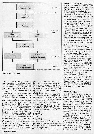
BlockI
The software crisis' Introduction
Block 2
SBlsendloaic
Bloc. 3
Functions
Bloc.
la ion and lists
81
Relations
Mod.Logic and proof
eMmsaral
1
Block
Mathematics in use
Aaprean editor
Blocks
Speak.g a diary svaksra Appacations
Block 8
,softwars blearPostscript
The stratum of the mune
pAq-r is easy to understand once youknows the language, but is incomprehen-sible otherwise. Unfortunately manyvery competent computer programmershave never met this sort of mathematics.For them, software engineering is aclosed book.It was for this sort of person that wewrote the training package EssentialMathematics for Software Engineers. Itconsists of three programmed learningtexts, each having three blocks; a fourthvolume contains a glossary; there is abibliography and a guide to the courseand a video cassette, which introduceseach of the blocks and explains some ofthe concepts in a more graphic way thanis possible in a straight text. The firstand last blocks are an introduction andpostscript to the other seven; blocks twoto six introduce the various mathemati-cal concepts, while blocks seven andeight are extended case studies.Block two looks at sets and logic. Thepurpose of this is to provide a
framework for writing down the essen-tial facts about a problem in an unam-biguous way and with the structure
2.52.rowcriro. Feb r .ry IND
clearly visible. What we need is to findsimple ways to put together sentences sothat is is easy to check whether they aretrue or false, and to specify sets in sucha way that if we take any particular ob-ject we can tell easily which sets itbelongs to.We may well ask why, when most of theideas are so simple, we cannot just writespecifications in ordinary English. Theanswer is that often we can, but Englishhas a number of peculiarities that canlead to ambiguities. The simplest ofthese is the use of the word or. If youram asked at breakfast in a hotel whetheryou would like cereals or orange juice,which of the following do you state asyour choice?(a) Cereals(b) Orange juice(c) Both(d) Yes pleaseHere is another example:"Peter and Andrew were fishermen".The statement can be paraphrased as(Peter was a fisherman) and (Andrewwas a fisherman) but"Peter and Andrew were brothers",
although of exactly the same gram-matical appearance, nnot beparaphrased as (Peter was a brother) and(Andrew was a brother). Once again oureveryday language is not precise,The next example is a little more subtle.An advertisement fora used car pro-claims only onerogreful driver." Let ustry to be precise. Let D be the set of alldrivers of the car. Let CD be the subsetof this consisting of all careful drivers ofthe can Then we wish to say that the setCD has only a single element. That, atleast, is what it seems to mean. But isthat what is really intended? Would youbuy a car which had had only one care-ful driver, and not worry about all theother, careless drivers which the car hadhad? Or does the advertisement implythat the set D has only one element, andthat that driver was careful? I suspectthat most people would assume that thesecond interpretation was the correctone.Contrast this with the assertion "Thecar has had only one serious accident."The grammatical structure is identical,yet most people would take the other in-terpretation, namely that the number ofserious accidents suffered by the car isone, but that there may have been other,non -serious ones. Where the same gram-matical structure can mean quite differ,eat things according to the context, thereis a clear indication that the language weare using to specify the structure is notgood enough for the purpose.Blbck three looks at functions. Thesecorrespond to an idealised computerprogram which has the structure:Input - Process - OutputIn the block we look at how the inputand output are specified and how theprocess relates the two. Functionsthemselves can be put together in differ-ent ways and this provides valuable in-sight into how programs can be struc-tured using smaller modules.
Recursion and listBlock four brings us to the related con-cepts of recursion and list. A list israther like a set, except that the elementsof it are in a specific order instead ofmerely bring somewhere in the set. It ispossible to insert and delete elementsand to sort and merge lists. Recursion isinvolved because it turns out to be moreconvenient to define a list in terms ofother, shorter, lists. The definition of aconcept in terms of itself is called arecursive definition. At first sight itlooks like cheating, but it is quite re-spectable if properly used and oftenleads to much shorter, easier programsthat leave much less scope for door.For example, suppose we have two listsof people, both sorted alphabetically,and we wish to merge them into one lie.Using recursion we start by comparingthe first elements of the two fists.

Whichever one comes first alphabeti-cally we write down and remove it fromits list. Now merge (this is the recursivestep) the two remaining lists by repeatingthe process and write the merged listafter the element we have written downalready. That is all, or nearly all. Wemust also explain what happens if one ofthe lists to be merged is empty. In fact itis easy: we just write down the other.The next block is to do with relations.This is not about brothers and sisters,aunts and uncles, though these are usedas an example to explain the idea. Thepoint is that mathematics is concernednot primarily with objects, but ratherwith the relationships between them.Programming too is about relationships,especially between the inputs to aprogram and' the associated outputs.Relations are at the heart of the specifi-cation process, just as functions relate tothe implementation of the program, and
it is vital to have a clear understandingof these two concepts.
ProofsThe final mathematical block deals withproofs. Part of the reason for usingmathematics for program specificationis that it not only helps to eliminate er-rors in programs, but even holds out thehope that we could prove our programsto be correct. This subject is still verymuch in its infancy, but the fundamentalnotions that would be needed in anysuch project are well known tomathematicians.Blocks seven and eight, as I have men-tioned, am extended case studies. Onecommon example that was used to il-lustrate many of the ideas in blocks twoto five was the monitor screen of a com-puter. In block seven much of thismaterial is pulled together to show howto design a simple text editor, specifying
its properties using the mathematicallanguage already developed. It falls farshort of a full wordprocessor, but it doesillustrate the techniques which could beused to design one Block eight is a quitedifferent problem. It is the design of anelectronic diary system for a small or-ganisation that holds meetings at regularintervals and needs to find when thepeople who matter are free.The package has been produced withfinancial assistance from the AlveyDirectorate M the UK and was written bya team from Sheffield City Polytechnic;the Hatfield Polytechnic; the Universityof Technology, at Loughborough, andICL. The video cassette, which is of ex-ceptionally high quality, was producedby the Open University and the BBC.Publishers of the complete package amthe Institution of Electrical Engineers,whose address is P.O. Box 26, Hitchin,Hertfordshire SG5 ISA, England.
NEW PRODUCTS
Earth Leakage Circuit Breaker.
ELCH from PR Electronics is used to de-tect the leakage current which occursdue to man touching to or bad insulation.By switching off Electrical Power it pre-vents electrical shock & fire hazards &damage of equipment because of excessleakage current.
The devices senses leakage current byspecial transformer which is comparedwith set value & if it exceeds i.e. whenfault occurs the relay operate & audiovisual indication is given.
The test key is used to check whether thedevice is working normally. ECLB's areavailable for 16A, 30 Amp. & for 30MA/100MA leakage current.
M/s. P. R. ELECTRONICS S3/C, RaulWadi, Mogal Lane Mahlm Bombay -400 016.
LCR Meter
ANDO ELECTRIC CO of Japan offersa 3-If2 digit LCR meter with a built incomparator. It can be used to measureaccurately inductance, capacitance, re-sistance, dissipation factor, quality fac-tor, ESR and conductance. Four mea-urement frequencies of 100 Hz, 120 Hz,110z and 10ICI'm are avaialable. The testignal level can be varied from 10 mV toV. The AB4305 also features automaticoffset "Zero" adjustment function.Series or parallel parameter can beelected. The ranges can be selected au-omatically or manually. The built Momparator comapres the measured
value with a preset value and passes if itis within the stipulated range. GP-IB in-terface is available as standard. DC biasan be applied to the specimum upto ±
35V or 100 mA.
M/s. Murugappa Electronics Ltd., Agency Divison 29, Second Street Kamaraj Avenue AdyarMadras 600 020.
ConductivityIndicator Controller1NM's DCIC - 400 Conductivity indi-cator -controller comes in two parts- a)Field mountable signal condition/trans-mitter and b) Panel mountable indicatorcontroller. Remote signal conditioner is
in a rugged. NEMA IV housing. Theusual problem associated with cablecapacitance errors in conductivity me as-surement is avoided by proce sing thesingal in the remote transmitter only.Distance between the cell and the panelinstrumeM could be unto 1000 ft. Thetransmitter can be mounted close to thecell on any pipe, horizontal or vertical.The panel indicator is withdrawablewithout disturbing the panel wiring giv-ing ease of servicing and replacement. Italso has a membrane keyboard withsplash -proof front panel capable of tak-ing considerable operational abuse.
Inputs and output signals are galvani-cally isolated from each other and fromthe indicator -controller electronics.High Alarm, Low Alarm, Setpoints Hi& Lo and span -Zero for current outputsare all programmable throught simplekey stroke. Alarm outputs are availableon relays.
Calibration of the instrument is ex-tremely simple, connect two knownvalue resistors successively in 'CAL'mode and 'ENTER' the eqquivalentconductivity data. Instrument takes careof the rest. Liquid temperature value canbe manually set or will be automaticallytaken care of by an independent temper-ature sensor.
Build -in self diagnostics checks thehealth of all the electronics. Should anyfault occur, a fault relay operates and theerror code is indicated on the front paneldisplay.
J. N. Marshall Pvt. Ltd. BombayPoona Road KaaarwadiPOONA -411034

illuminationindicateddigitally
AAA/Inn:1;i tn
This is a new and up-toclate measuring instrument; it is convenient, compactand digital: the DLM. The digital luxmeter is the latest member of our growingfamily of digital measuring instruments with simple construction, thanks toa high level of integration. It is intended for accurate measurement ofillumination, m two ranges: 0.1 ... 200 lux and 10 ... 20,000 lux. Its lowcurrent consumption of only 2 ... 4 mA makes the instrument independentof the mains and useful for portable applications.
LCD luxmeter
Table 1.11Ium.tionfigures for natural lightsources and guide valuesfor artificial lighting.
The luxmeter is suitable for many appli, be adhered to. Some of these guide valuescations, especially those associated with are listed in table l, and the table alsophotography and lighting. Particulady when indicates the illumination levels of naturalarranging and designing lighting systems, light sources. The illumination levels quotedproper lighting is important to prevent in table I for artificial light sources are onlyeyestrain. Poor lighting is false economy: average values.Illumination guide velum do exist and should The luxmeter presented here measures the
amount of illumination. It consists of threeT bl , units: the sensor and light.to-current con.a e
yen, the malogue-digital converter withNatural light momma ooy . ial reference voltage source, counter, latch,Clear night. full moon 0.3 BCD to ]segment decoder and LCD driver;Winn,. day in December and finally, the liquid crystal display.
with owrcast skySummer's den in June The sensorwith sovercat skyWinter's day in Oscsinnai A luxmeter is only useful if it 'me the
w,h clear sky to to ,,,pro.. 9,000 illumination just like the human eye andSummer's day in June for this reason the spectral sensitivities ofmin sunlight up to approx. 100.000 the two sensors (eye and photodiode) should
Artificial lighting be as similar as possible. So far, no photo -Candle iiehi at sensitive device has been made available
I m distance 1 having exactly Ne same spectral sensitivitySide roads as the human eye. One which comes fairlyMain toads too close, however, is the BPW 2.1 photodiode.Staircases. ral/WaY The dashed curve in figure 1 shows the
Platforms 30 ... 50 relative sensitivity of the eye as a functionSecondary rooms such asof the wavelength of light. The solid curveumarnmt. hall, etc. 120
ng-rooms and offices 260 represents the relative sensitivity of theClassrooms. shops. work. BPW 21 'Monodic:de and it can be seen that
shops goo both the eye and the photodiode am rela.craning offices. precision lively sensitive to visible light with a wave.
engineering workshops two length of approximately 555 cm. Theradiation range of visible light is aneroid.
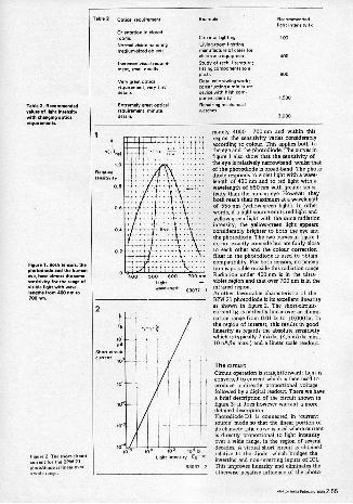
Table 2 Optical requirement 5vemPle Recommendedlight intensity
Table 2. Recommender!values of light intensitywith changing opticalrequirements.
Figure I. OPM tensors. thephotodiade and Me humaneye, have almost the samesensitivity for the range ofrisible light with wavelengths from 000 nin to700 nm.
Figure 2. T. whortpirCuitcurrent for the BM 21phototliode is linear overa wide range.
Orientation inclosedroorns Corridor lighting 102
Normal vision handling Living -room lighting:mediumrsived objects menv,Frture ef cam, Mr
electronic equipment 000
Increased visual require. Study of tech. literature;ment. small details fitting components to a
Very great opticalrequirement, very tingdetails
Extremely great opticalrequirement mMumdetails
Detailed drawing.worh:constructing a miniaturedevice with high com-Ponent densit2Repairing mechanicalwatches
800
1,500
3.000
2
Icre
1 10 10
Light intensitl,
83037 , 2
mately 4000 - 700 nm and within thisregion the sensitivity varies considerablyaccording to colour. This applies both tothe eye and the photodiode. The curves infigure I also show that the sensitivity ofthe eye is relatively nanowband, whilst thatof the photodiode is broad -band. The photo.diode responds to violet light with a wave-length of 430 nm and to red light with awavelength of 650 nm with greater sensi-tivity than the human eye. However, theyboth reach their maximum at a wavelengthat 555 nm (Yellow -green light). In otherwords, if a light source emits red light andyellow.green light with the same radiationintensity, the yellow -green light appearsconsiderably brighter to both the eye andthe photodiode. The two curves in figure 1do not exactly coincide hut are fairly closeto each other and the colour correctionfilter M the photodiode is used to obtaincompatibility. For both sensors, no percep-rton is possible outside this radiation range.Radiation under 400 nm is in the ultra.violet region and that over 700 nm is in theinfrared region.Another favourable characteristic of theBPW 21 photodiode is its excellent linearityas shown in figure 2. The shortoircuit.000raoilioiapetfaytlybnearooaraobl000.nation range from 0.011x to 10,0001x. Inthe region of interest, this results in goodlinearity as regards the absolute sensitivitywhich is typically 7 nA/lx, (4,5 nA/Ix min.,10 nA/lx max.) and a linear scale readout.
The circuitCircuit operation is straightforwmdi light isconverted to current which is then used toproduce a directly Proportional voltagefollowed by a digital readout There we havea brief description of the circuit shown infigure 3; it does however warrant a moredetailed description.Photodiode D1 is connected in 'currentsource' modem that the linear portion ofits characteristic curve is used where currentis directly proportional to light intensityover a wide range, in the region of severaldecades. A virtual short circuit is obtainedrelative to the diode, which bridges theinverting and non -inverting inputs of 1C1.This imprtives linearity and eliminates theotherwise negative influence of the photo.
eta.. Felmary nes 2.55

Figure 3. CompleteTh circuitof the luanatet.[flange -over fetility of thecurrentivoltage cooverter
luemeter witha range of0.1 ix toaonoo tu. this roughlymnweendstes.,wmillumination extendingfromeclearnightwfth
summer's day in June withovercast AI,
diode's leakage current. Further rotor.matins on this subject and photodiodeparameters along with various circuit eon.(imitations, is given elsewhere in this issueCO, IC!').The photocurrent is converted to a pro.portional voltage by means of ICI inconjuction with R1/122 and preset poten-tiometers P2/P3. In this circuit the opamp'soutput voltage must be equal to the voltagedrop across RI/P2 or R2/P3. This voltagedrop is directly proportional to the currentthrough the photodiode and the resistorvalues used. The resistors therefore determinethe measuring range. Since the voltageamplification of the light.to.current-to.voltage conversion circuit is relatively low,capacitor C2 must be added to prevent
Chloe the first stage has converted the lightintensity into an equivalent voltage, this canbe applied to the measuring input'IN HI'of IC2. A low-pass filter (RII/C4) is in-cluded to smooth out the 50 H. componentin artificial light.1C2 contains all the functions required inorder to obtain counting pulses from the
analogue input voltage, and feed them tothey segment decoder which is followed bythe LCD driver stage. The DVM chip alsoprovides a 2.8 V reference voltage, whichshares a common zero reference with thepotential divider R9/R10 and the lightsensor DI ('REF LO' and 'COMM', pins 35and 32 of IC2). A voltage of 100 mV ispresent anima 010 of the potential dividerand is applied to the 'REF NC input (pin 36)to ensure that the lusoneter gives fug soakdeflection fora measuring voltage of199.9 my at the 'IN HI' input (pin 31).The digits 1999 then appear on the display.Ti serve the function of inverting the BP(blackplane) signal of IC2 (pin 21) so thatthe decimal point DPI or DP2 is switchedon, depending on the setting of switch 52.
ConstructionAll componentiencept for the battery madswitches can be mounted on the printedcircuit board (figure 4). Components -.remounted on both sides of the pnb., whichresults in a compact design that will fit intoa small case. It is advisable to solder the
3
r4 LCO
8
172.3;2
IC2MOO
Nii:IZti24
BIM
2.56 musuriarua Nerve, 'sea

4
BPW 21 photodiode directly to the coppertrack ride of the p.c.b. Ensure that it iscorrectly connected! The LCD displayshould also be fitted to this side of thep.c.b. If pin 1 is not marked on the dis-play, the decimal points can be used fororientation. They are visible when thedisplay is viewed at an angle. The displaytcorrectly positioned on the p.c.b. whenhe decimal points are on the same side asthe heh, sensor.Ali other components are fitted to thecomponent side.
Calibration and alignment
A 40 W and 100 W bulb are required forcalibration; they are inserted in sequenceinto a reflectorless socket with no otherlight source switched on. No mirrors orreflecting surfaces should be in the vicin,ity, and brightly coloured was or ceilingsshould also be avoided before commencingto calibrate.
The offset alignment is done beforemounting the photodiode D1(!). Set the
display to 000 with Pl. In exceptional casesit may prove necessary to modify the valuesfor R3, R4 and P1 (R3 = R4 10 k andPI = 100k).
Mount the photodiode, set switch 32 tothe 20,000 lx range and position the
hummer 30 cm from the bulb (100 WI.Make sure that the bulb is directly abovethe sensor. Now adjust preset potentio-meter P3 to obtain a reading of 1.00 (Mx)on the display (i.e. 1,000 fun).
Change to the 40 W bulb and increasethe distance to 50 cm, than select the
20010 range. Adjust P2 to obtain a readingof 150.0 (In)
The luameter is now ready for use and wesuggest checking the illumination leechquoted in Table 1.
Parts list
RI,R5= 100462,R10= I kH3, a= 224R6. 47 kR7 .047146.011alheRg . 27 kP1= 50 k 147 Id presetP 2.100(P3.1 k 104orn presets
6pacitorrCI 56P02. 220 P03.100,10V04,06 .100 P06. 470 nCS = 220 n
Semiconductors:
ICI d 713130ICP. 7106L CD: 3% digit. dishheight 13mm
For example:Hamlin 3601 or 31102;LIU) 43D5003:Hitachi 1.60070C,H133IC.0
saiscelleneouv
SI .single.pole ontolt
67:t'ulate.pole charseover switch
Bent, clip for 0 VGatter,
decor /nee Feendayiess 2.57

NEW PRODUCTS .
Universal Eprom ProgrammerPR Electronic offer an intelligent Univ-ersal EPROM Programmer (PP -100),which is used along with ZX spectrumcomputer. The basic unit containshardware and software cassette to prog-ram the entire range of EPROM from2716 to 27512 and its subfamilies. Vari-ous other intelligent programming al-gorithms have bbeen used to reduce theprogramming time. The programmingvoltage, time and various other paramet-ers are user selectable by software. Fea-tures arm Blank checking, CopyEPROM into RAM, Verify, Entry andEdit of Data, Programming, Loading/Saving of data into cassette, mid Identifymode/Manual selection of EPROM.
M/s. P. R. ELECTRONICS 53/C, RauWadi, Mogal Lane Mahim Bombay400 016.
Electronic PCB Drill
INSTROL have developed a high speedhigh power PCB drilling machine thatcan drill holm of 0.2 to 2.6 min in printedcircuit boards. The PCB drill is a miniversion with base and stand so designedis to accomodate a big -sized PCB with awidth of 400 mm. The spindle height isadjustable. The speed can be adjusted byan electronic speed controller tomaximum of 14,500 RPM. The ACseries motor can draw upto 300 watts.The highly balanced rotor furnishes therotational power to the drill bit for pre-cise drilling operation. The drill can also
be used for drilling holes in soft metal Earth terminal to actual Earth/Groundsheets made of aluminium bakelite and and R and Y terminals to respective ph -fibre. ases. The green LED will glow (ON)
only if the phase sequence is correct.
M/s. Instrol (India) Pvt. Ltd. A-37Electronics Estate, GIDC G. M/s. Electro-Arts 4, Vaishati Gan-dhinagar-382 015. gappur Road Nashik422 005 Phone -
0253 -78452.
Insulation Tester
SCR Elektroniks manufacture the Di-gimeg, a portable digital meggerin twobasic versions-The LED model (suitabefor 230 V, 12 V optional) LCD modelwhich works on 9 v battery. Low cost andportability are said to be the two basicfeatures which make the Digimeg micable for applications on the field, in theshop Floor and in any sophisticated teslab.
SCR Elektroniks Opp. Fatima HighSchool Kirol Road Vidyavihar Bombay -000086.
Electronic Phase Sequence Indi-cator.THE Electro-Arts Solid -State phasesequence indicator is powered throughtest point R and does not required anyseparate supply. Output indimtions aregiven by LED and the greed LED is ONwhen phase sequence is correct. The in-strument has its own R and Y terminalswith the EARTH terminal. Connect the
Mixed ConnectorsTHE Type M mixed connectors, man-ufactured by ERNI Elektroapparategmbh of Fed Republic of Germany,meet DIN 41612 specifications. Besidesthe signal contacts for loads of up to 4 A,it is possibleup to 40 A and/or coaxial contacts. Thisrange is said to considerably increase thefield of application of these multi -pinconnectors in the telecommunimtionand data processing fields. Both the maleand female connector halves can beequipped with 2,4,6 or 8 special contactspaced on a 0.1" (2.54 mm) grid. Highurrent contacts are available for eitherolder or crimp connection. Coaxial
contacts. with a very low reflection fac-or, are available in various attains,
They have excellent electrical transmis-ion qualities and are insensitive to dis-
turbing electromagnetic fields.
M/s. A.T.E. Pvt. Ltd. Electronics Divi-sion 36 SDFF 2, SEEPZ Andheri (E) Bombay -400096.
2.66 5.10r Ind. memmdms

NEW PRODUCTS
Epabx UpgradedL&T manufacture CDOT's Version 3electronic private automatic branch ex-change (EPABX), designated ELTEX-112. The upgraded EPABX incorpo-rates fully digital technology comprisingtime division multiplexing pulse codemodulation (TDM-PCM) techniquewith stored program control (SPC). It isequipped with 128 ports enabling con-nections of 16 trunks or P&T lines and 96user extensions which includes benoperator console connections.
The Version -3 can be upgraded to 256ports enabling connections of 32 termi-nals and 192 user extensions with amaximum of four operator consoles.Features such as fully non -blocking,duplicated control scheme and extensiveself -diagnostics make the system de-pendable. Designed to operate in a non-airconditioned atmosphere, the ex-change is positivity suitable for Indianenvironmental conditions. Voice anddata switching capability is integratedinto the system to make it fully suitablefor complete office automation.
M/s. Larsen & Toubro Limited, TCOMDivision 563, Anna Salai Madras 600018
Digital Pocket ThermometerECONOMY have introduced a digitalpocket thermometer with a 10 mm LEDflourescent display that ensures clarity ofreadout. The unit is provided with drybatteries and intended for use with K -type thermocouples. Advanced elec-tronic in the meter offer linearisation ofthe E-typpe thermocouples over a rangeof -50 to 4-120(PC. The precision coldjunction is compensated with a perma-nently calibrated circuit.
Interchangeable thermocouple withstandard miniature male connector am
offered for air, water, oil and gas temp-erature in engines, surface temperatureof motors, pumps, bearings, extruders,ovens and furnaces, and other applica-tions in process industry.
M/s. Economy Electronics 15, SweeHome Plot No. 442 2nd floor Pitamber lane Off Tulsi Pipe Road Mahim Bombay -400 016 Phone:2862360 - 461482
Real Time ClockThe RTC -72421 module is a Real TimeClock designed for use in direct bus -compatible microprocessor applications.It features a built-in quartz oscillator,time and date function, and C-MOS cir-cuitry for low power consumption. Thebuilt-in crystal eliminates the need forexternal components and allows for easydesign. Three control registers provideStop, Hold, Reset, 30 Sec. Adjust, andInterrupt Masking Auto. Leap year and12 and 24 HOUR formate are also provided.
M/s. Sal Electronics (IN Associationwith Copwud Arts) Vitahore Estate Kuria Kirol Road Vidyavihar (W) Bombay -400 086 Ph: 5136601/5113094/5113095
OscilloscopeThe Tektronix 300 MHz digital oscillos-cope combines B -bit vertical resolutionwith 500 megasample per -second, dual -channel, and simultaneous acquisition.The combination of high resolution andhigh sampling rate gives users noticeablymore horizontal and vertical waveformdetail. The result is the ability to capturevery fast single -shot events with signific-antly improved accuracy, it is said The2440 enhances all the built-in automa-tion features pioneered by the other 2400digital oscilloscopes, in a compact,GPIS-compatible package. Besides the2440's familiar front -panel controls, set-up and measurement functions can be in-itiated by an ID button on the head ofTektronix new P6137 350 MHz passivevoltage probe. Up to 21 automatic mea-surements including amplitude, fre-quency, risetime, falltime, pulse widthand propagation delay can be madesiinultaneously. The 2440 provides built-in pass/fail decision making for anal -tended testing. known good waveformtemplates can be generated ofdownloaded into the scope and automat-ically compared to a live waveform. Vio-lations of the template are automaticallycaptured. A direct printer/plotter outputprovides automatic, time -stampeddocumentation.
M/s. Hinditron Services Pvt. Ltd. Test& Measurement Division 69/A, L. Jag-muhandass marg Bombay -900 006.
2.68 elelclo, FablUary

NEW PRODUCTS
Modular Test & Measuring Inshu-ments.
Scientific offer a range of high precisionprofessional grade test and measuring in-struments in modular form. The main-frame has a built-in power supply to ac-comodate any two modules of the.8000Series. The enhanced features and highaccuracy of the modules makes themuseful for calibration checks as well. Fea-tures include 20 MHz generator withhighly stable amplitude, 3 ns Rise andFall time pulses, distortion measurementup to 0.01%, frequency counting withperiod measurement, and event count-ing facility at a measurement rate of 300
The range includes 6 modules: Fre-quency counter HM 802140.1 Hz to IGHz with period mment andevent counting facility,easure300 ms), Pulsegenerator HM 8035 3 ns rise 20 MHz fre-quency range' separate +ve and -ye out-put facility; Function generator HM8030 + (0.01 Hz to 1 MHz, FM input andDC -off -set facility); Sine wave generatorHM 803/(20 Hz to 20 MHz); Distortionmeter HM 8027-(20 Hz to 20 KHz formeasuring distortion to within 0.01%;and milli -ohm -meter HM 8014- (Resol-ution 100 microohms, Range 200 mohms to 20K ohms, audible fault locaterand diode testing facility.
Scientific Mes-Technik Pet. Ltd. B-14,Pologround Industrial Estate Induce -452 803.
CABLE TIES
The Novoflex Cab-lok cable tie is a ver-stile method of binding hardnessing andfixing cables. The tie is self-locking andcannot work loose. Thge one-piece cabletie can be used in virtually any bundleconfiguration and available in a varietyof sizes to cover bundling diameter of 1.6
to 106 mm. Novoflex Cab -lock ties sys-Mm is immensely strong and virtually in-destructible.
Each tie incorporates a non -return, cam -action locking device which ensures thatonce in place the tie will never come offor slacken. It maintains holding strengthover a temperature extreme of -60°C to+110°C.
It is available in natural translucent andblack for indoor use. Black ties are suita-ble for outdoor use, including under-ground, since they are resistant to ultra-violet radiation.
For further details to contact:
NOVOFLEX CABLE CARE SYSTEMS Post Box No. 9159 Calcutta -700016. Phone: 290482, 295939, 293991Gram: SAFTDUCT
LCR Meter with Comparator
Ando Electric Co. of Japan offer theAG4304, 4/1/2 -digit LCR meter with abuilt-in comparator, which can be usedto measure inductance, capacitance, re-sistance, dissipation factor, quality fac-tor, ESR and conductance. Four memsurement frequencies of 100 Hz, 120 Hz,I ICHz are available. The test signal levelcan be varied from 10 mV to 1 V. TheAG4304 also features automatic offsetZero adjustment function. Series or par-rallel parameter can be selected. Theranges can be selected automatically ormanually. The built-in comparator com-pares the measured value with a presetvalue and passes if it is within the stipu-lated range. GP -1B interface is availableas standard. DC bias can be applied tothe specimen .pro ±35 V or 100 mA.
Mts. Murugappa Electronics Ltd.Agency Division 29, Second street Kamaraj Avenue Adyar Madras -600020. Phone: 41 33 87
Photoelechic PrIxImIty Switch
Electro-Arts manufacture a range ofphotoelectric proximity switch.. Theself-contained photoelectric scannercombines a modulated beam infraredlight source and receiver in a single hous-ing which can be easily installed. Theunit detects objects by sensing reflec-tions of light source from object surface.These switches detect diffusely a reflect-ing surfaces or objects including metal ornon-metals paper cloth plastics etc.These are applicable in -contactsensing, switching, controlling nand reg-ulating various processes, plants,machines etc. for factory automation.
The switches are available in a standardbrass plated housing of 18 mm dia as wellas in a rectangular size. These work on10-24 VDC, output is available fromNPN or PNP transistors with 100 mAoutput current.
M/s. ElectrwArts 4, Vaishali Gan -gamic Road Nmhik.422 005 0253-7852
2.70 a.. India F.., 1989

NEW PRODUCTS
Tube Axial Cooling FansManufactured by Ralliwolf, these havealready found acceptance with all lead-ing manufacturers of computers, photo-copiers and others. The 120x 120x38mmmodel seen in the photograph is the firstof cooling fans planned by the comanyand is presently available in 2311V and115V AC. This cooling fan is guaranteedto deliver an airflow above 95 elm freeair and develop a static head of 9.5 mmof water. Fitted with imported miniatureball bearings, the life of the cooling fanis assured to last much beyond 30,000hours,
the model IMA-15 has sucessfully with-stood tests such as shock and vibration,salt spray, dust and rain that are stipu-lated for defence use.
The configuration of the frame of thiscooling fan has been so designed as tofacilitate one-to-one replacement ofmany imported cooling fans.
MAC ELECTRONICS 405 Hill viewindustrial estate Off L.B.S. Marg,Ghatkopar (WI, Bombay 400 086
Thermocouples/RTD Sensors
Ghemitronies India offers full range ofthermocouple sensors for chromelalumel, copper constant, iron constatn,Pt -Pt 13% Rh, Pt -Pt 10% Rh, and RTDPt 100. Them sensors are available indifferent shapes and sizes depending onapplication. The range includes surfacetemperature probes (exposed junction)up to 800° C for solid surface hot plate,furnace. etc, gas probe up to 500°C; bowtype probe up to 600°C, mainly for mov-ing rollers, pipes and circular hot junc-tion application; penitration probe up to
800'C for semi -frozen type materials,resins, cold storage frown material;needle probe up to 800°C for flat sur-faces; mineral insulted probes withMonel metal sheath or Inconel sheath forspecial applications such as hazardouschemicals, acids, furnace oils, etc. Alsooffered are compensating cables andthermocouple wires for all these ther-mocouples.
TChemitronies India Block 4 Plot 10
Society Road Above 10B Bombay 400 060
PotentiometersSakae of Japan offers a range of poten-tiometers, dials and servo components.The range covers multi -turn, single -turn,low torque on linear, linear motion,multi -elements, trimming, oil filled,A.C. and contactless potentiometers.Servo components include motorisedpotentiometers, servo amplifiers,switching amplifiers, D.C. powersupplies, helical switches, etc. Applica-tion includes consumer, professfional,defence, machine tool, reboties andmedical electronics.
M/s. Universal Automation 47, Mitra-mandal Pune- 411 0099
Computer Ribbon Re -InkingMachineThe Track Inker for computer electronictypewriter ribbons is basically used forreinking of used/new computer ribbonsat user's location. The tabletop devicesupports an types of fabric ribbons car-tridges and ribbon width varying from 6to 30 mm. The machine consists of a basewith an electrical drive and ink reservoir.The ribbon is rotated by the drive and asd passes around there ervoir, ink istransferred to the ribbons via a capillarymesh which ensures even ink distribu-tion. The ink used is a special type calleddot matrix ink and supplied with themachine. Automatic timers are also orailable for auto shut-off of the drive.
M/s. Track Engineers 187/5225, San -matt Pantangar Chatkopar (E) Bombay -400 075 Ph: 362111, 381989(Shashank)
Desktop Semiconductor DeviceTester
Scientific Test Inc. of USA manufacturethe Model 5150 desktop, automatic dis-crete semiconductor test system whichcan set electrical parameters of traiacs,SCRs, transistors, MOSFETS, Zeners,MOVs, diodes etc. Suitable for originaequipment manufacturers for incominginspection of semiconductor devices, thesystem features as standard a self tesdiagnostic routine which functionallylean the complete system in under 5 secnods.
M/s. A.T.E. Pvt. Ltd. (Electronics Di.Rion) 36, MOE II, SEEPZ, Andheri
(E) BOMBAY -4000996 6300195

R N No 39881 /83
DO IT YOURSELF
;1:1fore Junior Computer bookanyone wishingto
become familiar withopomputers. this book givesthecr
nity to build andprogramaverypersonal computer
reasonablereasonablecost.
LEARN -BUILT)PROGRA itn
the practical introductimon
to a powerful syste
The Indian reprint comes to you from
elelatSend full oayment bym No CPacking
p,,,tagor,heclue Pease.
to: EICkTOR ElECiRQVkSPVT Lid.52C, or Road, Grant Road9ombay_400 007.