Embed Size (px)
Citation preview

7-1
The GreenHills Tool Chain
Multi 2.1/3.5 Differences
Build Environment Overview
Build Through Debug Review
Linking Files
ROM and RAM Execution
Multi 2000 Configuration

7-2
Multi 2.1/3.5 - Directory Structure
Multi v2.1C:\green
\libsrc
\armtsf
\armtsfb
Multi v3.5C:\ghs
\libsys
\arm4
\arm4b

7-3
Multi 2.1/3.5 - System Library
• System related functions – libsys.a
• Contains customized IO stubs – ind_io.c
• No longer replace system library in GHS directory– /ghs/arm4b/libsys.a
• New custom GHS library– ghs.o
• Replaced io file during final link– na2.bld

7-4
Multi 2.1/3.5 - Build File
• Compatible with multi2000 v3.5– na1.bld, na2.bld, bsp.bld, …
• Automatically upgraded format when modified– Insert additional files
• Options are added or removed– byteorder
– bigendian
– c_options
• New format not compatible with v2.1
• Using an editor to avoid format change– Wordpad
– ultraedit

7-5
Multi 2.1/3.5 – new Compiler
• Stricter compliance to C standard– Casting variable types
• Additional warnings generated– No line feed
– Variable used when not initialized
– Variable not used
• NETOS files cleaned– bsp, header files, examples

7-6
Overview of Multi 2000 Build Environment

7-7
Major Components
• By Green Hills Software
• Integrated Development Environment (IDE) Includes– Builder
– Compiler
– Linker
– Editor
– Source Debugger
– Version Control
– Run-Time Error Checking

7-8
Builder Window
• This is the main builder window

7-9
Graphical User Interface
• Multi-2000 provides a color-assisted text editor

7-10
Adding files to the project
• C files and libraries are added to the project simply by a multi-selectable dialog window

7-11
Build Through Debug Review
7-12
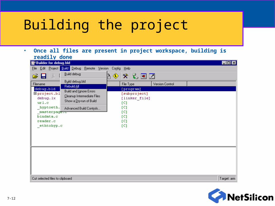
Building the project
• Once all files are present in project workspace, building is readily done
7-13
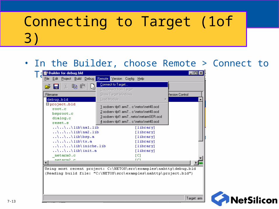
Connecting to Target (1of 3)
• In the Builder, choose Remote > Connect to Target.

7-14
Connecting to Target (2 of 3)
• Enter OCDSERV command line.

7-15
Connecting to Target (3 of 3)• Two new windows
• IN/OUT –Displays Printf’s
• TARGET—can read/write to Memory/CPU

7-16
Starting Debugger
• In the Builder select Debug > debug

7-17
Debugger Features
• Set Break Points-Software and Hardware
• Step through code
• Examine C-code
• Examine Interlaced Assembly
• Examine values of variables, registers, memory

7-18
Debugger Windows
• Interlaced Assembler displayed
• Color enhanced buttons

7-19
Download code to Target• Click “play” button or (F5)

7-20
Run Program
• Program is Running• Use breakpoints or step through code

7-21
Breakpoints
• NET+OS supports both software and hardware breakpoints.
• Software breakpoints (instruction fetches) are only possible while debugging from RAM– Actual instruction is replaced with a special bit pattern that forces the
ARM into debug mode.
– Unlimited number of software breakpoints available.
• Hardware breakpoints (data accesses) are possible while debugging from RAM or ROM.– Triggered by particular address access.
– Maximum of one hardware breakpoint at a time. (Green Hills Limitation)

7-22
Software Breakpoints
• Adding a software breakpoint takes one click!
7-23
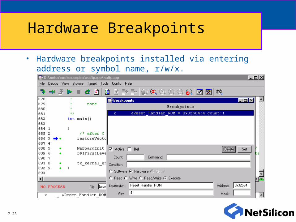
Hardware Breakpoints
• Hardware breakpoints installed via entering address or symbol name, r/w/x.

7-24
Debugging in a multi threaded operating environment – ThreadX Tools
• Multi-2000 has a number of specific tools for debugging and analyzing ThreadX.

7-25
ThreadX Tools

7-26
ThreadX Tools

7-27
Linking Files

7-28
Introduction
• The linker places text & data into the appropriate sections of memory, as defined by the – User-supplied section map, or
– Default linker section map
• Application can benefit by splitting the program into sections such that it will more readily support different types of memories. Factors include:– Speed of parts (performance requirements)
– Cost & availability

7-29
Linker Directives File
• Major GHS supplied linker directives:
.picbase Base of text sections
.text Program text
.rodata Read-only data
.rosdata Small, read-only data
.secinfo Information on section layout of the program
.data Initialized variables
.bss Zero-initialized variables
.heap Size and location of runtime heap
.stack Size and location of runtime stack

7-30
Linker Directives File (cont.)
• NETSilicon provided linker directives
• Common linker attributes– align(expr) - Section will start on first expr-byte aligned address following previous section
– pad(expr) - Linker will reserve expr bytes for this section in memory
– ROM(expr) - Section becomes a ROMmable copy of expr. Section inherits the attributes and data of expr, while expr is modified to reserve address space only (as if it were all padding with no data)
.netosstackStack for each processing mode, grows downward. Please refer to init.s
.free_memArea of memory used by the THREADX kernel to create timer and root threads. This should not be used for any other purpose

7-31
ROM and RAM Execution

7-32
Basic RAM & ROM requirements for NET+OS
• 512KB – 1MB Flash Recommended– Primarily for code storage
– Code execution for low-end applications
• 2MB – 8MB RAM Recommended– Data buffering for DMA channels
– Thread stacks
– Heap
– Place holder for new image download
– Code execution for higher-end applications

7-33
System Memory Map
Memory Range Memory Device Cache Option
0x00000000 - 0x00FFFFFF RAM CACHE
0x02000000 - 0x000FFFFF ROM SAFE
0x03000000 - 0x03001FFF NVRAM
0x04000000 - 0x04FFFFFF RAM DATA
0x06000000 - 0x060FFFFF ROM CACHE
0x08000000 - 0x08FFFFFF RAM INSTRUCTION
0x0A000000 - 0x0A0FFFFF ROM CACHE
0x0C000000 - 0x0CFFFFFF RAM NOT
0x0E000000 – 0x0E0FFFFF ROM CACHED

7-34
System Memory Map
• BSP provided memory map is designed with cache in mind.
• Same map will work with or without cache.
• Entire memory map configured using 2 control registers per chip select.
• Address bit masking allows for multiple memory images – ideal for setting up cacheable regions.

7-35
Relative application speed
• FLASH memory typically 90-120ns read access time.– Can decrease access time to 35-50ns by leaving flash chip “on”
all the time.
• SDRAM typically 7-10ns access time.
• Running from RAM is typically faster.

7-36
Supporting FTP FLASH upgrade
• FTP server must be running out of either Flash or RAM.
• FLASH update is invoked by an FTP client requesting to “put” file of special keyword filename.
• File is transferred to Net+ARM system memory buffer (RAM).
• A subsequent procedure, running in RAM, burns Flash with this new image.– Running in RAM is the key to this step.

7-37
Project Structure
Note ramimagezip.bld is main project, including only subproject, linker.-> Also includes project options.-> Inherits additional options from a parent project.

7-38
ramimagezip.bld - what it looks like
#!build
default:
program
:elxr_map_option=map
:elxr_map_option=numeric_sort
:postexec=gmemfile -s ramimagezip -o ram.bin
:postexec=compress ram.bin ramimagezip.bin
:postexec=bin2obj ramimagezip.bin .\zobjs\ramimagezip.o
project.bld
subproject
ramimagezip.lx
linker_file

7-39
project.bld - contents
Note the hierarchy - project.bld includes only source files and libraries. Conclusion - the same project.bld can be used with several programs.

7-40
project.bld - what it looks like
#!build
default:
subproject
root.c
C
bsproot.c
C
dialog.c
C
decompress.c
C
reset.s
assembly
na1.lib
library
na2.lib
library
bsp.a
library
tcpip.a
library
tx.a
library
appconf.h
include_file
cont…

7-41
3 Ways to Run…
ramimagezip rom romzip
Application Execution
Boot Execution RAM*
RAM
ROM
ROM
ROM
RAM
*Note - Executable downloaded with Debugger
7-42
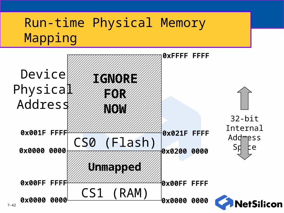
Run-time Physical Memory Mapping
0x0000 0000
0x0200 0000
CS1 (RAM)
CS0 (Flash)
0x00FF FFFF
0x021F FFFF
Unmapped
IGNOREFORNOW
32-bit Internal Address Space
0x0000 0000
0x0000 0000
0x00FF FFFF
0x001F FFFF
DevicePhysicalAddress
0xFFFF FFFF

7-43
ramimagezip Executable Location
CS1 (RAM)
CS0 (Flash)
Unmapped
IGNOREFORNOW
0x0000 0000
0x00FF FFFF
Executable Location
32-bit Internal Address Space
0xFFFF FFFF

7-44
Memory Map - ramimagezip
0x0000 0000
0x0080 0000
0x0000 1000Vector Table
Data Section
stack
heap
bssdata
Unused
Text (instructions)
Constant Data
Initialized r/w Data
.sdabase
.picbase
.pidbase
unknown until link
unknown until linkUnused
Top of Physical RAM
Explicitly definedin linker file(ramimagezip.lx)
CS1(RAM)

7-45
rom.bld Executable Location
CS1 (RAM)
CS0 (Flash)
Unmapped
IGNOREFORNOW
0x0000 0000
0x0200 0000
0x00FF FFFF
0x02FF FFFF
Executable Location
32-bit Internal Address Space

7-46
Rom-based Memory Map - rom.bld
0x0000 0000
0x0200 0000
Vector Table
Data Section
stack
heap
bssdata
Unused
Text (instructions)
Constant Data
Initialized r/w Data
.sdabase
.picbase
.pidbase
Unused
Top of Physical RAM
Top of Physical Flash
CS0 (Flash)
CS1 (RAM)
7-47
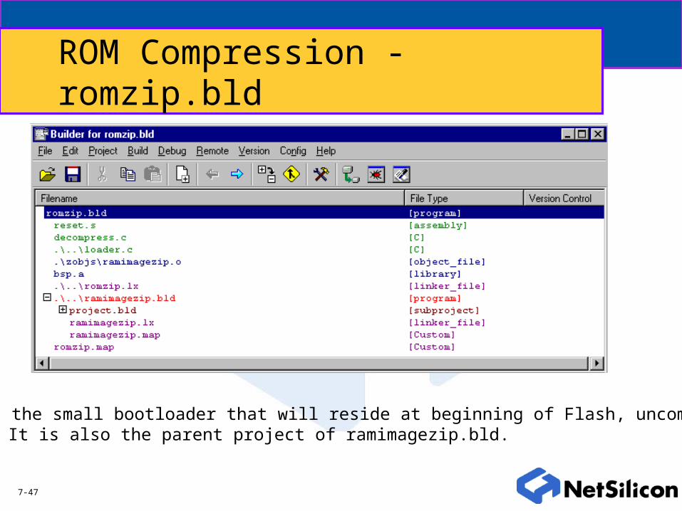
ROM Compression - romzip.bld
romzip is the small bootloader that will reside at beginning of Flash, uncompressed.-> It is also the parent project of ramimagezip.bld.

7-48
romzip.bld - what it looks like
#!build
default:
program
:c_option=noasmwarn
:elxr_map_option=numeric_sort
:arm_option=bigendian
:arm_cputype=arm7tm
:object_dir=.\zobjs
:driver_opts=-map
entry=Reset_Handler_ROM
:sourcedirs=.\..\..\..\bsp
:sysincdirs=.\..\..\..\..\h
:sysincdirs=.\..\..\..\..\h\threadx
:defines=NET_OS
:defines=ENABLE_FLASH_COMPRESSION
:postexec=gmemfile -s romzip -o romzip.bin
reset.s
assembly
decompress.c
C
.\..\loader.c
C
.\zobjs\ramimagezip.o
object_file
bsp.a
library
.\..\romzip.lx
linker_file
.\..\ramimagezip.bld
program
romzip.map
Custom

7-49
romzip.bld Executable Location
CS1 (RAM)
CS0 (Flash)
Unmapped
IGNOREFORNOW
0x0000 0000
0x0200 0000
0x00FF FFFF
0x02FF FFFF
Executable Location
32-bit Internal Address Space
Sameas
rom.bld

7-50
Memory Map - romzip.bld
0x0000 0000
0x0200 0000
Vector Table
Data Section
stack
heap
bssdata
Unused
Text (instructions)
Constant Data
Initialized r/w Data
.sdabase
.picbase
.pidbase
Unused
Top of Physical RAM
Top of Physical Flash
Sameas
rom.bld
CS0 (Flash)
CS1 (RAM)

7-51
ramimage.o location, pre-decompression
0x0200 0000Text (instructions)
Constant Data
Initialized r/w Data
.picbase
Unused ramimage.o•Compressed ramimage•Linked with ramimage.lx•Symbol name ram_buffer_0
CS0 (Flash)

7-52
Decompression and Relocation
0x0000 0000Vector Table
Data Section
stack
heap
bssdata
Unused
CS1 (RAM)
Text (instructions)
Constant Data
Initialized r/w Data
.picbase*
Unused
Text (instructions)
Constant Data
Initialized r/w Data
Unused
CS0 (Flash)
RAMIMAGE_START
*RAMIMAGE_START must match .picbaseas defined in ramimagezip.lx !!!
After relocation, flash is no longer used,and execution starts at .picbase - Finalmemory map same as ramimagezip !
0x0200 0000
decompress.c

7-53
Summary
• Develop & debug with ramimagezip.bld– Must Open romzip.bld, to inherit proper include directories, etc.
• double-click ramimagezip.bld from within romzip.bld
• Once desired functionality reached, simply compile romzip.bld– romzip.bin will be generated
– Download to flash
• Power cycle will invoke romzip to run from Flash
• After about 15 seconds, ramimagezip will be running– From RAM
– Flash no longer used at this point
– Original ramimagezip memory map now in effect

7-54
Multi 2000 Configuration

7-55
Introduction
• MULTI-2000 is a user configurable IDE
• Users can control:– Compiler options
– Linker options
– Visual look and feel

7-56
Project | Options

7-57
General Tab

7-58
Optimization Tab

7-59
Run-time Error Tab

7-60
Configuration Tab

7-61
Action Tab

7-62
Advanced Tab

7-63
Project | Language Options

7-64
C Tab

7-65
Project | CPU Options
7-66
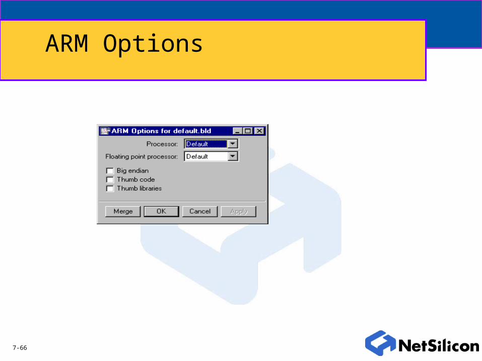
ARM Options

7-67
Project | Toolchain Options

7-68
Linker Tab

7-69
Assembler Tab
7-70
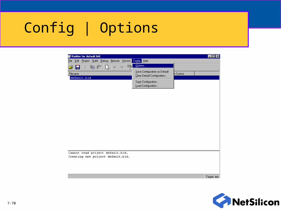
Config | Options

7-71
General Tab
7-72
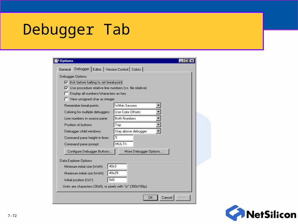
Debugger Tab

7-73
Editor Tab

7-74
Version Control Tab

7-75
Colors Tab

7-76
Summary
• For further reading consult Building and Editing with Multi2000, Green Hills Software(M32W89NG)