Embed Size (px)
Citation preview
6.772SMA5111 - Compound Semiconductors
Lecture 8 - Epitaxy cont.; Device Processing - Outline
• Epitaxy techniques (concluding discussion from Lecture 6)
Liquid phase epitaxyGas phase epitaxy
1. Vapor phase epitaxy; 2. Metallorganic chemical vapor deposition Molecular beam epitaxy
1. Solid source; 2. Gas source; 3. Metalloganic; 4. Chemical beam
• Device processing Etching technology
1. Wet etches a. Selective etches; b. Anisotropic etches; c. Isotropic etches
2. Dry etching
Doping technology1. Diffusion2. Ion implantation
Device isolation
Ohmic contacts
C. G. Fonstad, 2/03 Lecture 8 - Slide 1
Mismatched epitaxy - letting layers relax
Graded lattice constant structures
Linear grading Step grading•
• There is no general agreement on which approach is superior andthe choice often one of convenience and/or practicality.
• Because the last layer is often not fully relaxed, it is common tograde to a certain level and then step back, as seen in the structureon the left. In this way a fully relaxed top structure can be realized.
Relaxed, mismatched layers are termed "metamorphic" C. G. Fonstad, 2/03 Lecture 7 - Slide 2
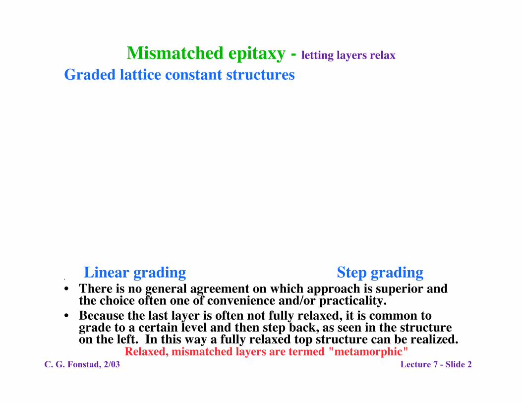
Liquid Phase Epitaxy -Explode view of an LPE "boat"
Machined pyrolytic graphite Material:
Growth ambient: Purified hydrogen at atmospheric pressure Within a quartz tube in a resistance heated furnace
C. G. Fonstad, 2/03 Lecture 7 - Slide 3
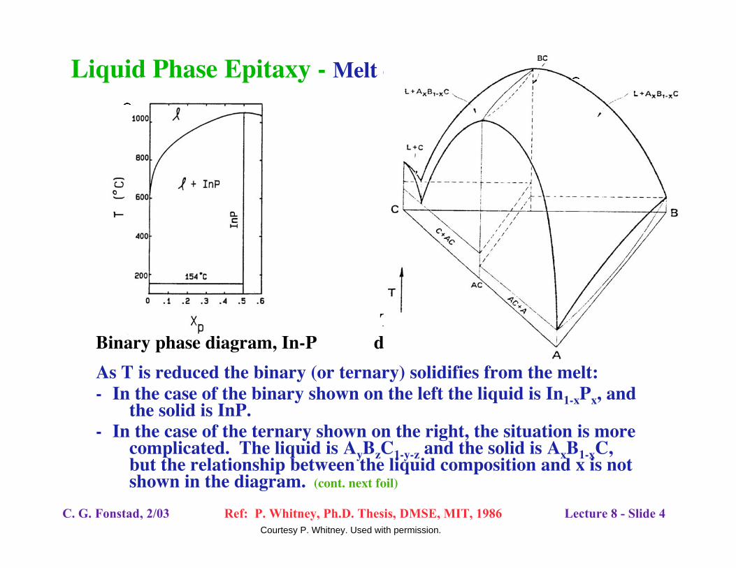
Liquid Phase Epitaxy - Melt calculation
Ternary phase Binary phase diagram, In-P diagram, A-B-C
As T is reduced the binary (or ternary) solidifies from the melt: - In the case of the binary shown on the left the liquid is In1-xP , andx
the solid is InP. - In the case of the ternary shown on the right, the situation is more
complicated. The liquid is AyB C1-y-z and the solid is AxB1-xC,zbut the relationship between the liquid composition and x is notshown in the diagram. (cont. next foil)
C. G. Fonstad, 2/03 Ref: P. Whitney, Ph.D. Thesis, DMSE, MIT, 1986 Lecture 8 - Slide 4
Courtesy P. Whitney. Used with permission.

Melt calculation, cont.
Projected isotherm and tie line for In-Ga-As system
Liquid Phase Epitaxy -
Equilibrium liquidus for InGaAs lattice-matched to InP
The relationship between the ternary liquid composition and theternary solid composition is displayed by a tie line between aprojected isotherm and ternary solid line, as shown on the left,
Or by a plot of liquid composition verses temperature for a specificsolid composition of interest, as shown on the right.
C. G. Fonstad, 2/03 Ref: P. Whitney, Ph.D. Thesis, DMSE, MIT, 1986 Lecture 8 - Slide 5
Courtesy P. Whitney. Used with permission.
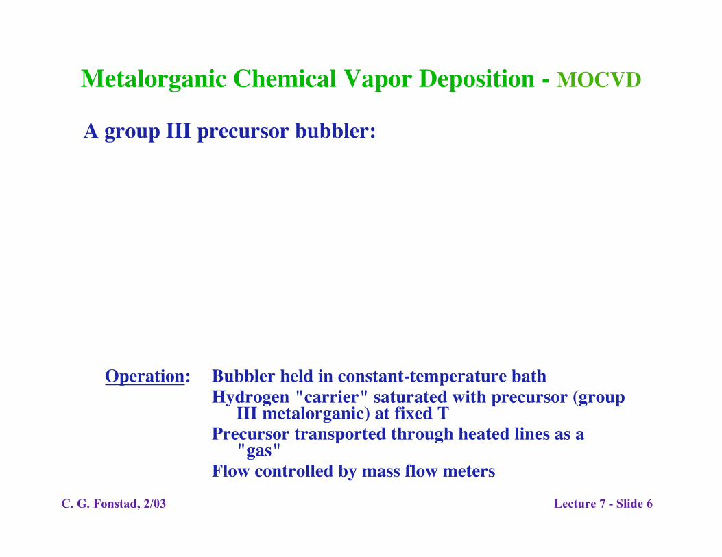
Metalorganic Chemical Vapor Deposition - MOCVD
A group III precursor bubbler:
Operation: Bubbler held in constant-temperature bath Hydrogen "carrier" saturated with precursor (group
III metalorganic) at fixed T Precursor transported through heated lines as a
"gas" Flow controlled by mass flow meters
C. G. Fonstad, 2/03 Lecture 7 - Slide 6
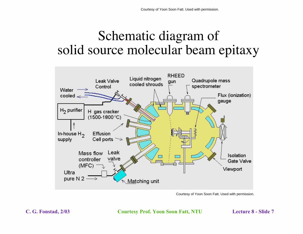
Courtesy of Yoon Soon Fatt. Used with permission.
Schematic diagram ofsolid source molecular beam epitaxy
Courtesy of Yoon Soon Fatt. Used with permission.
C. G. Fonstad, 2/03 Courtesy Prof. Yoon Soon Fatt, NTU Lecture 8 - Slide 7

Solid source molecular beam epitaxysystem (NTU)
Courtesy of Yoon Soon Fatt, NTU.
Base pressure: 10-11 Torr (with cryogenic cooling)
Pressure during epitaxial growth: 10-8 to 10-7 TorrC. G. Fonstad, 2/03 Courtesy Prof. Yoon Soon Fatt, NTU Lecture 8 - Slide 8
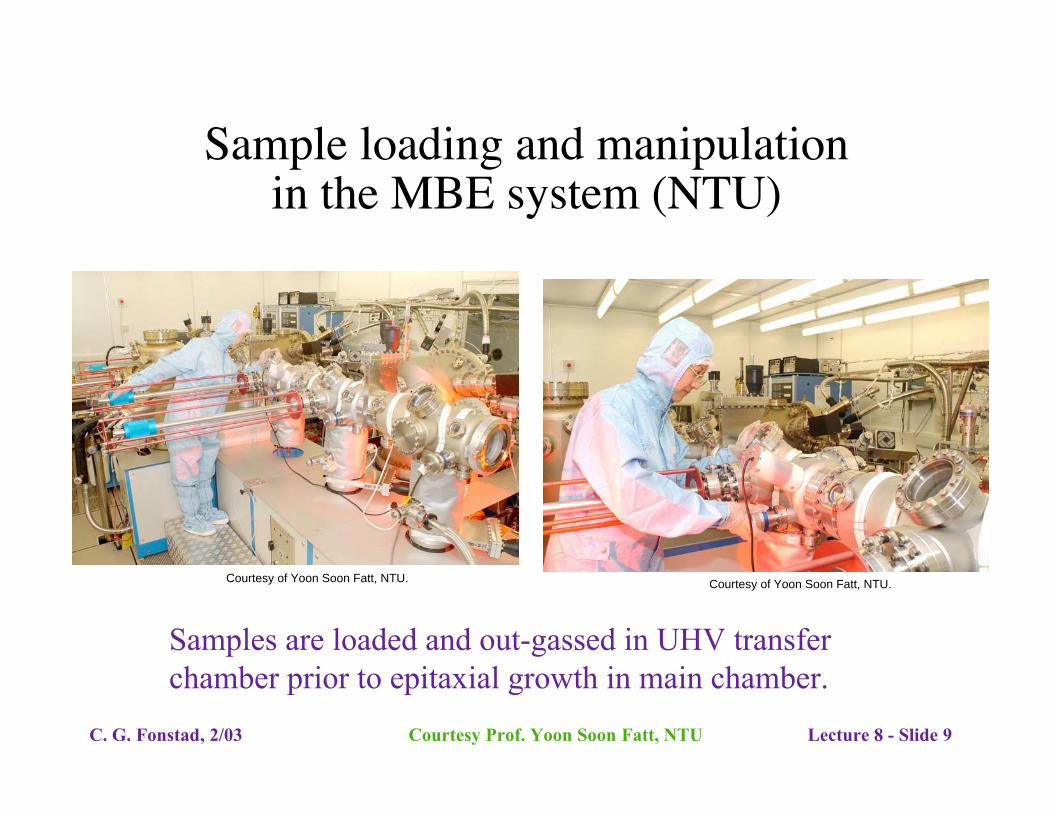
Sample loading and manipulationin the MBE system (NTU)
Courtesy of Yoon Soon Fatt, NTU. Courtesy of Yoon Soon Fatt, NTU.
Samples are loaded and out-gassed in UHV transferchamber prior to epitaxial growth in main chamber.
C. G. Fonstad, 2/03 Courtesy Prof. Yoon Soon Fatt, NTU Lecture 8 - Slide 9

Single filament effusion cell(In, Ga and Al)
Crucible
Thermocouple
Heating element
Heat screenMounting flange
Courtesy of Yoon Soon Fatt, NTU.
C. G. Fonstad, 2/03 Courtesy Prof. Yoon Soon Fatt, NTU Lecture 8 - Slide 10

Valved arsenic and phosphorus crackersource (NTU)
Courtesy of Yoon Soon Fatt, NTU. Courtesy of Yoon Soon Fatt, NTU.
Valved arsenic cracker Valved phosphorus cracker
For fast interruption and abrupt change of As or P flux.
C. G. Fonstad, 2/03 Courtesy Prof. Yoon Soon Fatt, NTU Lecture 8 - Slide 11
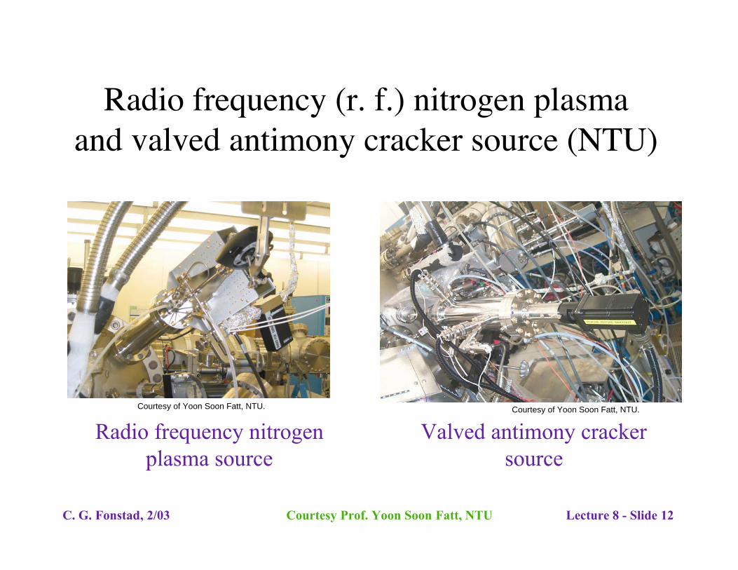
Radio frequency (r. f.) nitrogen plasmaand valved antimony cracker source (NTU)
Courtesy of Yoon Soon Fatt, NTU. Courtesy of Yoon Soon Fatt, NTU.
Radio frequency nitrogen Valved antimony cracker
plasma source source
C. G. Fonstad, 2/03 Courtesy Prof. Yoon Soon Fatt, NTU Lecture 8 - Slide 12