Embed Size (px)
Citation preview

Seismic isolation of the
Jamuna multipurpose bridge
M.G. Castellano, A. Cestarollo
- JJOJO &/wz%%mo D. - f D -
Abstract
The Jamuna Multipurpose (or Bangabandhu) Bridge consists mainly of a viaductequal to 4.9 km length. The static arrangement is that of a typical multi-spancontinuous Gerber girder bridge; each box girder has 6 or 7 spans of 99.750 m.FIP Industrial supplied bearings and seismic devices which were to be designedto satisfy the dual aim of: 1) guaranteeing a «classic» static scheme duringnormal service operation, providing fixed points for horizontal forces(transversal and longitudinal) and guiding devices to allow longitudinalmovements of the deck with respect to the piers; 2) to provide multidirectionaldampers able (in the event of an earthquake) to transmit to each pier a horizontalload lower than 4250 kN, limiting at the same time the displacement within ±200 mm. The above targets have been achieved through the design andinstallation of 1 18 multidirectional pot bearings (VASOFLON type) and 48 steelhysteretic dampers of types MEP and MEPOT. Each damper consists of 42 steeldissipating elements (double tapered spindles) working in parallel, and hasyielding force and displacement approximately equal to 3500 kN and 30 mm,respectively. Beyond that limit, the dissipating spindles deform plastically andthus control the horizontal force transmitted to the pier. The damper maximumforce at 200 mm displacement has been experimentally verified to be lower than4250 kN. The difference between types MEP and MEPOT consists in thepresence in the latter of two shock-transmission units (OT devices), that are ableto accomodate longitudinal displacements due to thermal deformations of thedeck, whilst locking during earthquakes. Thus, the MEPOT type is used at theexpansion points and the MEP type at the fixed points of the girder. Duringearthquakes the behaviour of MEP and MEPOT devices are identical.
Transactions on the Built Environment vol 38 © 1999 WIT Press, www.witpress.com, ISSN 1743-3509

648 Earthquake Resistant Engineering Structures
1 Introduction
The aim of this paper is to discuss the seismic devices supplied by FIPIndustrial for the Jamuna Multipurpose Bridge in Bangladesh. As it is wellknown, seismic isolation can substantially improve seismic performance ofdifferent types of structures, and often accrues significant savings in constructioncosts. In particular, it is an economical way to protect piers and foundations, aswell as abutments in some cases, when bridges are located in highly seismic-prone areas such as that of the above mentioned structure. The Jamuna Bridge islocated approximately 30 km away from an active fault (Russell [1]). Bridgeseismic isolation aims to reduce loads as well as distribute the same throughoutsub-structural elements. Also, in the case of the Jamuna bridge, the designengineer's objective in selecting the seismic isolation system was to limit loadson the foundations.
2 Description of the structure
The infrastructure lies 120 km north of the capital Dhaka and comprises a 4.9 kmviaduct. In plan view, the viaduct conforms to a 12,000 m constant radius,curved longitudinal axis. The static arrangement is that of a typical multi-spancontinuous Gerber girder bridge with girders 6 or 7 spans long (99.750 m).
The deck has a box girder structure, achieved by on-site connection ofprefabricated precasted reinforced concrete girder elements. It has a 18.5 m wideslab and its height varies from 2.75 to 5.5 m (Russell [1]).
3 Design requirements
The design of the supporting system was conceived considering the behaviour ofthe structure from a dynamic point of view during the seismic event rather thanjust the static point of view, at it is usually done.
In terms of design Code reference, the Specification complies with BS5400; specifically, with Parts 9.1 & 9.2 for the bearings.
As a precise requirement of Specifications and in order to reduce theamount of horizontal load applied at the top of the piers, especially duringseismic events with a ground peak acceleration of 0.47 g, FIP was asked tocustom design a device capable of keeping horizontal loads generated by themass of the superstructure within the range indicated in Figure 1, allowing ± 200mm plastic displacements.
As there are no guided or fixed bearings located in the main piers and thedeck rests on free sliding pot bearings of 33000 and 30000 kN vertical loadcapacity, the design of the seismic devices had to meet the followingrequirements:• guarantee a «classic» static scheme under normal service conditions
providing fixed points for horizontal forces (transversal and longitudinal) andguiding devices to permit longitudinal deck movements with respect to thepiers;
Transactions on the Built Environment vol 38 © 1999 WIT Press, www.witpress.com, ISSN 1743-3509

Earthquake Resistant Engineering Structures 649
provide a multi-directional damper system (able to withstand 15 cycles at thedesign displacement) under seismic conditions;provide a lateral stop-block, acting at displacement of 250 mm, designed for4500 kN capacity;all the bearings as well as the seismic devices should be easily replaceablewithout excessive deck jacking.
5000
0 15 30 50 100 150 200 s (mm)
Figure 1: Steel hysteretic damper nominal curve requested,indicating range of accepted values.
4 The seismic isolation system
The seismic design requirements were fulfilled by FIP Industrial through thedesign of multidirectional steel hysteretic dampers comprising double taperedspindles as dissipating elements. These dampers, whose sole aim is to controlhorizontal forces, are combined with free sliding pot bearings (VASOFLONtype) that serve to transmit vertical loads (up to 33000 kN each) and permithorizontal displacements in all directions.
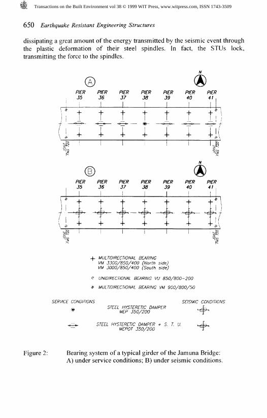
Figure 2 shows the bearing system under both service and seismicconditions of a typical multi-span girder of the Jamuna Multipurpose Bridge.Specifically, the second girder (starting from the east end pier), resting on sevenpiers. Under service conditions (Figure 2-A), there is a fixed point (pier 38)where a seismic device type MEP is located. On the expansion points, there areseismic devices type MEPOT, capable of accommodating longitudinal deckdisplacements (due to thermal deformations, creep, and shrinkage), thanks to thepresence of Shock-Transmission Units (STUs) coupled in series to steelhysteretic dampers. During an earthquake, all seismic devices behave identically,
Transactions on the Built Environment vol 38 © 1999 WIT Press, www.witpress.com, ISSN 1743-3509
650 Earthquake Resistant Engineering Structures
dissipating a great amount of the energy transmitted by the seismic event throughthe plastic deformation of their steel spindles. In fact, the STUs lock,transmitting the force to the spindles.
JL
( i
PIER35
1
t
I
PIER36
1
t
I
PIER37|
j__
PIER38
\
t
1
PIER39
\
t<3 & —
i
PIER40
\
-EE>
PIER
"1
t i l
P/f/? P/£>? PJ5 Jg J| 1
* f 4" ~
'."T i "
f£R P7 J
5L,_ ̂
fER P6 J
^ -^
r£7? PP 4
^ -^
f/? P0 4
^— ̂
W;
j/
-f. MULTIDIRECTIONAL BEARINGVM 3300/850/400 (North side)VM 3000/850/400 (South side)
$ UNIDIRECTIONAL BEARING VU 850/800-200
f MULTIDIRECTIONAL BEARING VM 900/800/50
SERVICE CONDITIONS SEISMIC CONDITIONSSTEEL HYSTERETIC DAMPER
MEP 350/200
STEEL HYSTERETIC DAMPER + S. T. U.MEPOT 350/200
Figure 2: Bearing system of a typical girder of the Jamuna Bridge:A) under service conditions; B) under seismic conditions.
Transactions on the Built Environment vol 38 © 1999 WIT Press, www.witpress.com, ISSN 1743-3509

Earthquake Resistant Engineering Structures 651
Figure 3: Elevation view, along the transverse direction, of the seismic deviceMEPOT 350/200: 1) spindle dissipating element; 2) ShockTransmission Unit (STU); 3) stop-block element.
Figure 4: Elevation view, along the longitudinal direction, of the seismic deviceMEPOT 350/200: 1) spindle dissipating element; 2) STU;3) stop-block element.
Transactions on the Built Environment vol 38 © 1999 WIT Press, www.witpress.com, ISSN 1743-3509

652 Earthquake Resistant Engineering Structures
Each damper, of both the MEP and MEPOT types, comprises 42 double-taper spindles working in parallel, designed for a yield force approximately 80kN each and a maximum force of 100 kN each at 200 mm displacement. Thespindle (single or double-taper) is one of the dissipating elements typically usedby FIP Industrial to achieve steel hysteretic dampers. One of its mainadvantages is its intrinsic multi-directionality. The STUs in each MEPOT deviceare two, with a nominal maximum force of 2100 kN each. They comprisedouble-action hydraulic cilinder-piston systems filled with silicon compound.Figures 3 and 4 show elevation views of a MEPOT seismic device along thebridge transverse and longitudinal directions respectively. As already mentioned,the MEP type is identical save for the absence of STUs.
It is worth mentioning that service loads (i.e., wind, braking actions, etc.)do not stress the dissipating elements owing to the use of "sacrificial restraints",designed to fail at a 500 kN horizontal load. Said sacrificial restraints impede anydisplacement in the dampers of the fixed type and the transverse movements onthose of the expansion type. In the event of a strong earthquake, the sacrificialrestraints fail and the dampers are activated.
The seismic devices provided by FIP can also withstand greaterdisplacement than the ± 200 mm design value. The spindles themselves canwithstand significantly higher displacements (see § 5). At any rate, under anextremely unlikely earthquake higher than the design-level, a stop-blockintervenes with the onset of ± 250 mm transverse displacements.
FIP Industriale also supplied other structural devices for the Jamuna Bridge.These were unidirectional and multi-directional VASOFLON pot bearings withvariable vertical load from 8500 to 11500 kN, installed on the West End and EastEnd piers as well as at the Gerber girder connections, as well as special foamrubber bumpers to limit damage to the vertical girder interfaces due to possiblehammering.
In conclusion, the FIP Industriale supply for the Jamuna MultipurposeBridge comprised the following:# N. 48 VASOFLON Bearings VM 3300 (at the North Side)• N. 48 VASOFLON Bearings VM 3000 (at the South Side)• N. 2 VASOFLON Bearings VM 1150* N. 6 VASOFLON Bearings VM 900# N. 8 VASOFLON Bearings VU 850# N. 41 Steel Hysteretic Dampers MEPOT 350/200• N. 7 Steel Hysteretic Dampers MEP 350/200• N. 84 Bumpers with a maximum load of 60 tons.
5 Testing
Functional tests were carried out at the FIP Industriale laboratory on both spindledissipating elements and a STU (herein described), as well as on pot bearingsand foam rubber bumpers.
A group of four full-scale spindles were tested together (see Figure 5)imposing displacement at a velocity of 100 mm/min. First, 15 complete
Transactions on the Built Environment vol 38 © 1999 WIT Press, www.witpress.com, ISSN 1743-3509

Earthquake Resistant Engineering Structures 653
hysteretic cycles at the design displacement of ± 200 mm were imposed; then.two of the elements were displaced until one of them failed. Said failure held at a315 mm displacement. The fifth cycle was selected as reference cycle tocompare test results to design requirements. Figure 6 shows the hysteretic loopmeasured during this cycle on the four elements. The average yield force anddisplacement were 317.5 kN (corresponding to a force of 3333.75 kN on thecomplete device consisting of 42 elements) and 27 mm, respectively. During thesame cycle, the average maximum force at ± 200 mm was of 397.5 kN(corresponding to 4173.75 kN for the complete device), and thus in compliancewith the design limit value. Figure 7 shows the force vs displacement curvemeasured on a pair of spindles during the 16^ cycle, until failure.
Three different types of tests were carried out on the STU at three differenttemperatures (10, 27 and 40 °C):
1) low velocity test;2) impact test;3) dynamic test.In the first test, the displacement was imposed at a velocity of 0.03 mm/s,
i.e. the actual thermal velocity of the bridge, for at least a complete cycle of ± 20mm. This test aimed to verify that the reaction force opposed by the STU tothermal movements is lower than the specified value (e.g.: 3 % of the nominalload, at ambient temperature). With reference to the nominal load, the measuredvalues were the following: 3.35 % at 10 °C, 2.16 % at 27 °C, and 1.20 % at 40°C. These differences are due to the changes in the viscosity of the siliconcompound with the temperature.
The objective of the impact test was to verify whether the STU is capableof reaching the predicted reaction under an impulsive action (at velocity higherthan 20 mm/s). Therefore, a thrust was applied, both in tension and compression,at 26 mm/s. The measured force was 2260 kN, higher than the minimumprescribed value (2100 kN), and the corresponding displacement was about 17mm (about 7 % of the total device stroke).
The dynamic test consisted of a force-imposed sinusoidal test, withamplitude equal to the design load and frequency as high as possible withavailable power system, for a certain number of cycles. This test aims to verifythat the device response will be almost constant during an earthquake. The actualinputs in the different tests had a maximum load in the range 2000 -r- 2260 kN,while the frequency was in range 0.4 -=- 0.5 Hz. Testing specifications requiredthat the displacement induced by the applied load should not exceed 7 % of themaximum design stroke for the ambient temperature test. The displacementsmeasured range from 4.78 % during the first cycle to 5.76 % during the 20*cycle.
6 Conclusions
The seismic isolation of the Jamuna Multipurpose Bridge represents asuccessful! example of application of seismic devices consisting of multiple
Transactions on the Built Environment vol 38 © 1999 WIT Press, www.witpress.com, ISSN 1743-3509

654 Earthquake Resistant Engineering Structures
spindle steel hysteretic dampers and shock transmission units, as well as otherstructural devices such as free sliding bearings, expansion joints and rubberbumpers. The adoption of the seismic isolation approach permitted endowing thebridge with complete protection against the design earthquake at significantssavings in construction costs compared with a traditional approach. Specifically,concerning the foundations. The seismic isolation system was custom designedin such a way as to maintain the classic structural scheme under serviceconditions and fulfill all design requirements. Furthermore, all the structuraldevices are easy to install. All such devices were subjected to acceptance tests,and fulfilled the design requirements.
References
1. Russell, H., Judgement day for Jamuna, Bridge design & engineering, III,12, pp. 30-35, 1998.
Figure 5: The four spindle dissipating elements undergoing test.
Transactions on the Built Environment vol 38 © 1999 WIT Press, www.witpress.com, ISSN 1743-3509

Earthquake Resistant Engineering Structures 655
-250 -200 -150 -100 -50 0 50 100 150 200 250
Figure 6: Force vs displacement measured on four spindles (5* cycle).
0 30 60 90 120 150 180 210 240 270 300 330 360
s(mm)
Figure 7: Force vs displacement on two spindles up to failure (16*** cycle).
Transactions on the Built Environment vol 38 © 1999 WIT Press, www.witpress.com, ISSN 1743-3509

656 Earthquake Resistant Engineering Structures
Figure 8: A spindle during a preliminary test (350 mm imposed displacement).
Figure 9: The seismic device MEPOT 350/200 (cf. Figures 3 and 4).
Transactions on the Built Environment vol 38 © 1999 WIT Press, www.witpress.com, ISSN 1743-3509