Embed Size (px)
Citation preview

Relion® Protection and Control
630 seriesCommissioning Manual


Document ID: 1MRS756801Issued: 2014-11-28
Revision: DProduct version: 1.3
© Copyright 2014 ABB. All rights reserved

CopyrightThis document and parts thereof must not be reproduced or copied without writtenpermission from ABB, and the contents thereof must not be imparted to a thirdparty, nor used for any unauthorized purpose.
The software or hardware described in this document is furnished under a licenseand may be used, copied, or disclosed only in accordance with the terms of suchlicense.
TrademarksABB and Relion are registered trademarks of the ABB Group. All other brand orproduct names mentioned in this document may be trademarks or registeredtrademarks of their respective holders.
WarrantyPlease inquire about the terms of warranty from your nearest ABB representative.
http://www.abb.com/substationautomation

DisclaimerThe data, examples and diagrams in this manual are included solely for the conceptor product description and are not to be deemed as a statement of guaranteedproperties. All persons responsible for applying the equipment addressed in thismanual must satisfy themselves that each intended application is suitable andacceptable, including that any applicable safety or other operational requirementsare complied with. In particular, any risks in applications where a system failure and/or product failure would create a risk for harm to property or persons (including butnot limited to personal injuries or death) shall be the sole responsibility of theperson or entity applying the equipment, and those so responsible are herebyrequested to ensure that all measures are taken to exclude or mitigate such risks.
This product has been designed to be connected and communicate data andinformation via a network interface which should be connected to a securenetwork. It is the sole responsibility of the person or entity responsible for networkadministration to ensure a secure connection to the network and to take thenecessary measures (such as, but not limited to, installation of firewalls, applicationof authentication measures, encryption of data, installation of anti virus programs,etc.) to protect the product and the network, its system and interface included,against any kind of security breaches, unauthorized access, interference, intrusion,leakage and/or theft of data or information. ABB is not liable for any such damagesand/or losses.
This document has been carefully checked by ABB but deviations cannot becompletely ruled out. In case any errors are detected, the reader is kindly requestedto notify the manufacturer. Other than under explicit contractual commitments, inno event shall ABB be responsible or liable for any loss or damage resulting fromthe use of this manual or the application of the equipment.

ConformityThis product complies with the directive of the Council of the EuropeanCommunities on the approximation of the laws of the Member States relating toelectromagnetic compatibility (EMC Directive 2004/108/EC) and concerningelectrical equipment for use within specified voltage limits (Low-voltage directive2006/95/EC). This conformity is the result of tests conducted by ABB inaccordance with the product standards EN 50263 and EN 60255-26 for the EMCdirective, and with the product standards EN 60255-1 and EN 60255-27 for the lowvoltage directive. The product is designed in accordance with the internationalstandards of the IEC 60255 series.

Safety information
Dangerous voltages can occur on the connectors, even though theauxiliary voltage has been disconnected.
Non-observance can result in death, personal injury or substantialproperty damage.
Only a competent electrician is allowed to carry out the electricalinstallation.
National and local electrical safety regulations must always befollowed.
The frame of the IED has to be carefully earthed.
The IED contains components which are sensitive to electrostaticdischarge. Unnecessary touching of electronic components musttherefore be avoided.
Whenever changes are made in the IED, measures should be takento avoid inadvertent tripping.


Table of contents
Section 1 Introduction.......................................................................3This manual........................................................................................3Intended audience..............................................................................3Product documentation.......................................................................4
Product documentation set............................................................4Document revision history.............................................................4Related documentation..................................................................5
Symbols and conventions...................................................................5Symbols.........................................................................................5Document conventions..................................................................5Functions, codes and symbols......................................................6
Section 2 Starting up......................................................................11Factory and site acceptance testing.................................................11Commissioning checklist..................................................................11Checking of the power supply..........................................................12Energizing the IED............................................................................12
Checking the IED operation.........................................................12IED startup sequence .................................................................12
Setting up communication between PCM600 and the IED...............13Writing an application configuration to the IED.................................14Checking CT circuits.........................................................................15Checking VT circuits.........................................................................16Checking the RTXP test switch .......................................................16Checking transducer circuits............................................................17Checking binary input and output circuits.........................................17
Checking the binary input circuits................................................17Checking the binary output circuits..............................................17
Checking RTD inputs and mA outputs.............................................18RTD input circuits........................................................................18mA outputs circuits......................................................................18
Checking optical connections...........................................................19
Section 3 Establishing connection and verifying the stationcommunication...............................................................21Setting the station communication....................................................21Verifying the communication............................................................21
Section 4 Testing IED operation.....................................................23Preparing the IED to verify settings..................................................23
Table of contents
630 series 1Commissioning Manual

Activating the test mode...................................................................24Preparing the connection to the test equipment...............................25Connecting test equipment to the IED..............................................25Releasing the function to be tested..................................................26Verifying analog primary and secondary measurement...................26Testing the protection functionality...................................................28
Section 5 Troubleshooting .............................................................29Fault tracing......................................................................................29
Identifying hardware errors..........................................................29Identifying runtime errors.............................................................29Identifying communication errors.................................................29
Checking the communication link operation...........................30Checking the time synchronization.........................................30
Running the display test..............................................................31Indication messages.........................................................................31
Internal faults...............................................................................31Warnings.....................................................................................32Additional indications...................................................................32
Correction procedures......................................................................33Factory settings restoration.........................................................33Changing and setting the password............................................33Identifying IED application problems...........................................33
Inspecting the wiring...............................................................34Inspecting the RTD wiring......................................................37
Section 6 Glossary.........................................................................43
Table of contents
2 630 seriesCommissioning Manual

Section 1 Introduction
1.1 This manual
The commissioning manual contains instructions on how to commission the IED.The manual can also be used by system engineers and maintenance personnel forassistance during the testing phase. The manual provides procedures for checkingof external circuitry and energizing the IED, parameter setting and configuration aswell as verifying settings by secondary injection. The manual describes the processof testing an IED in a substation which is not in service. The chapters are organizedin chronological order in which the IED should be commissioned.
1.2 Intended audience
This manual addresses the personnel responsible for commissioning, maintenanceand taking the IED in and out of normal service.
The commissioning personnel must have a basic knowledge of handling electronicequipment. The commissioning and maintenance personnel must be wellexperienced in using protection equipment, test equipment, protection functionsand the configured functional logics in the IED.
1MRS756801 D Section 1Introduction
630 series 3Commissioning Manual

1.3 Product documentation
1.3.1 Product documentation set
Pla
nnin
g &
pu
rcha
se
Eng
inee
ring
Inst
alla
tion
Com
mis
sion
ing
Ope
ratio
n
Mai
nten
ance
Dec
omm
issi
onin
g,
dein
stal
latio
n &
dis
posa
l
Quick start guide
Quick installation guide
Brochure
Product guide
Operation manual
Installation manual
Engineering manual
Technical manual
Application manual
Communication protocol manual
Point list manual
Commissioning manual
GUID-C8721A2B-EEB9-4880-A812-849E1A42B02C V1 EN
Figure 1: The intended use of documents during the product life cycle
Product series- and product-specific manuals can be downloadedfrom the ABB Website http://www.abb.com/relion.
1.3.2 Document revision historyDocument revision/date Product series version HistoryA/2009-09-15 1.0 First release
B/2011-02-23 1.1 Content updated to correspond to theproduct series version
C/2012-08-29 1.2 Content updated to correspond to theproduct series version
D/2014-11-28 1.3 Content updated to correspond to theproduct series version
Download the latest documents from the ABB Websitehttp://www.abb.com/substationautomation.
Section 1 1MRS756801 DIntroduction
4 630 seriesCommissioning Manual

1.3.3 Related documentationProduct series- and product-specific manuals can be downloaded from the ABBWebsite http://www.abb.com/substationautomation.
1.4 Symbols and conventions
1.4.1 Symbols
The electrical warning icon indicates the presence of a hazardwhich could result in electrical shock.
The warning icon indicates the presence of a hazard which couldresult in personal injury.
The caution icon indicates important information or warning relatedto the concept discussed in the text. It might indicate the presenceof a hazard which could result in corruption of software or damageto equipment or property.
The information icon alerts the reader of important facts andconditions.
The tip icon indicates advice on, for example, how to design yourproject or how to use a certain function.
Although warning hazards are related to personal injury, it is necessary tounderstand that under certain operational conditions, operation of damagedequipment may result in degraded process performance leading to personal injuryor death. Therefore, comply fully with all warning and caution notices.
1.4.2 Document conventionsA particular convention may not be used in this manual.
• Abbreviations and acronyms are spelled out in the glossary. The glossary alsocontains definitions of important terms.
• Push button navigation in the LHMI menu structure is presented by using thepush button icons.
1MRS756801 D Section 1Introduction
630 series 5Commissioning Manual

To navigate between the options, use and .• Menu paths are presented in bold.
Select Main menu/Settings.• WHMI menu names are presented in bold.
Click Information in the WHMI menu structure.• LHMI messages are shown in Courier font.
To save the changes in non-volatile memory, select Yes and press .• Parameter names are shown in italics.
The function can be enabled and disabled with the Operation setting.• The ^ character in front of an input or output signal name in the function block
symbol given for a function, indicates that the user can set an own signal namein PCM600.
• The * character after an input or output signal name in the function blocksymbol given for a function, indicates that the signal must be connected toanother function block in the application configuration to achieve a validapplication configuration.
1.4.3 Functions, codes and symbolsTable 1: Functions included in the IEDs
Description IEC 61850 IEC 60617 ANSIProtection
Three-phase non-directionalovercurrent protection, low stage
PHLPTOC 3I> 51P-1
Three-phase non-directionalovercurrent protection, high stage
PHHPTOC 3I>> 51P-2
Three-phase non-directionalovercurrent protection,instantaneous stage
PHIPTOC 3I>>> 50P/51P
Voltage dependent overcurrentprotection PHPVOC I(U)> 51V
Three-phase directionalovercurrent protection, low stage
DPHLPDOC 3I> -> 67-1
Three-phase directionalovercurrent protection, high stage
DPHHPDOC 3I>> -> 67-2
Distance protection DSTPDIS Z< 21, 21P, 21N
Automatic switch-onto-fault logic CVRSOF SOTF SOTF
Fault locator SCEFRFLO FLOC 21FL
Autoreclosing DARREC O -> I 79
Non-directional earth-faultprotection, low stage
EFLPTOC I0> 51N-1
Non-directional earth-faultprotection, high stage
EFHPTOC I0>> 51N-2
Non-directional earth-faultprotection, instantaneous stage
EFIPTOC I0>>> 50N/51N
Table continues on next page
Section 1 1MRS756801 DIntroduction
6 630 seriesCommissioning Manual

Description IEC 61850 IEC 60617 ANSIDirectional earth-fault protection,low stage
DEFLPDEF I0> -> 67N-1
Directional earth-fault protection,high stage
DEFHPDEF I0>> -> 67N-2
Harmonics based earth-faultprotection
HAEFPTOC Io>HA 51NHA
Transient/intermittent earth-faultprotection
INTRPTEF I0> -> IEF 67NIEF
Admittance-based earth-faultprotection
EFPADM Yo> -> 21YN
Multi-frequency admittance-basedearth-fault protection
MFADPSDE I0> ->Y 67YN
Wattmetric earth-fault protection WPWDE Po> -> 32N
Stabilised restricted earth-faultprotection LREFPNDF dI0Lo> 87NL
Third harmonic based stator earthfault protection H3EFPSEF
dUo(3H)>/Uo(3H)< 27/59THD
High-impedance based restrictedearth-fault protection HREFPDIF dI0Hi> 87NH
Rotor earth-fault protection MREFPTOC Io>R 64R
Phase discontinuity protection PDNSPTOC I2/I1> 46PD
Negative-sequence overcurrentprotection
NSPTOC I2> 46
Negative-sequence overcurrentprotection for machines MNSPTOC I2>G/M 46G/46M
Phase-reversal protection PREVPTOC I2>> 46R
Three-phase thermal overloadprotection for feeder
T1PTTR 3Ith>F 49F
Three-phase thermal overloadprotection, two time constants T2PTTR 3Ith>T/G 49T/G
Three-phase thermal overloadprotection for motors MPTTR 3Ith>M 49M
Motor startup supervision STTPMSU Is2t n< 48,66,14,51LR
Motor load jam protection JAMPTOC Ist> 51LR
Emergency start ESMGAPC ESTART ESTART
Loss of load supervision LOFLPTUC 3I< 37
Three-phase current inrushdetection
INRPHAR 3I2f> 68
Transformer differential protectionfor two-winding transformers TR2PTDF 3dI>T 87T
High-impedance or flux-balancebased differential protection formachines MHZPDIF 3dIHi>G/M 87GH/87MH
Stabilized differential protection formachines MPDIF 3dI>G/M 87G/87M
Three-phase overvoltageprotection
PHPTOV 3U> 59
Table continues on next page
1MRS756801 D Section 1Introduction
630 series 7Commissioning Manual

Description IEC 61850 IEC 60617 ANSIThree-phase undervoltageprotection
PHPTUV 3U< 27
Positive-sequence overvoltageprotection
PSPTOV U1> 47O+
Positive-sequence undervoltageprotection
PSPTUV U1< 47U+
Negative-sequence overvoltageprotection
NSPTOV U2> 47O-
Residual overvoltage protection ROVPTOV U0> 59G
Directional reactive powerundervoltage protection
DQPTUV Q>-->,3U< 32Q,27
Reverse power/directionaloverpower protection
DOPPDPR P> 32R/32O
Underpower protection DUPPDPR P< 32U
Frequency gradient protection DAPFRC df/dt> 81R
Overfrequency protection DAPTOF f> 81O
Underfrequency protection DAPTUF f< 81U
Load shedding LSHDPFRQ UFLS/R 81LSH
Low voltage ride throughprotection function
LVRTPTUV U<RT 27RT
Overexcitation protection OEPVPH U/f> 24
Voltage vector shift protection VVSPPAM VS 78V
Three-phase underexcitationprotection UEXPDIS X< 40
Three-phase underimpedanceprotection UZPDIS Z< GT 21GT
Circuit breaker failure protection CCBRBRF 3I>/I0>BF 51BF/51NBF
Tripping logic TRPPTRC I -> O 94
Multipurpose analog protection MAPGAPC MAP MAP
Protection-related functions
Local acceleration logic DSTPLAL LAL LAL
Communication logic for residualovercurrent
RESCPSCH CLN 85N
Scheme communication logic DSOCPSCH CL 85
Current reversal and WEI logic CRWPSCH CLCRW 85CRW
Current reversal and WEI logic forresidual overcurrent
RCRWPSCH CLCRWN 85NCRW
Control
Bay control QCCBAY CBAY CBAY
Interlocking interface SCILO 3 3
Circuit breaker/disconnectorcontrol
GNRLCSWI I <-> O CB/DC I <-> O CB/DC
Circuit breaker DAXCBR I <-> O CB I <-> O CB
Disconnector DAXSWI I <-> O DC I <-> O DC
Table continues on next page
Section 1 1MRS756801 DIntroduction
8 630 seriesCommissioning Manual

Description IEC 61850 IEC 60617 ANSILocal/remote switch interface LOCREM R/L R/L
Synchrocheck SYNCRSYN SYNC 25
Tap changer control with voltageregulator OLATCC COLTC 90V
Generic process I/O
Single point control (8 signals) SPC8GGIO - -
Double point indication DPGGIO - -
Single point indication SPGGIO - -
Generic measured value MVGGIO - -
Logic Rotating Switch for functionselection and LHMI presentation
SLGGIO - -
Selector mini switch VSGGIO - -
Pulse counter for energy metering PCGGIO - -
Event counter CNTGGIO - -
Supervision and monitoring
Runtime counter for machines anddevices
MDSOPT OPTS OPTM
Circuit breaker conditionmonitoring
SSCBR CBCM CBCM
Fuse failure supervision SEQRFUF FUSEF 60
Current circuit supervision CCRDIF MCS 3I MCS 3I
Trip-circuit supervision TCSSCBR TCS TCM
Station battery supervision SPVNZBAT U<> U<>
Energy monitoring EPDMMTR E E
Measured value limit supervision MVEXP - -
Hot-spot and insulation ageingrate monitoring for transformers HSARSPTR 3Ihp>T 26/49HS
Tap position indication TPOSSLTC TPOSM 84M
Power quality
Voltage variation PHQVVR PQMU PQMV
Voltage unbalance VSQVUB PQMUBU PQMUBV
Current harmonics CMHAI PQM3I PQM3I
Voltage harmonics (phase-to-phase)
VPPMHAI PQM3Upp PQM3Vpp
Voltage harmonics (phase-to-earth)
VPHMHAI PQM3Upe PQM3Vpg
Measurement
Three-phase current measurement CMMXU 3I 3I
Three-phase voltagemeasurement (phase-to-earth)
VPHMMXU 3Upe 3Upe
Three-phase voltagemeasurement (phase-to-phase)
VPPMMXU 3Upp 3Upp
Residual current measurement RESCMMXU I0 I0
Table continues on next page
1MRS756801 D Section 1Introduction
630 series 9Commissioning Manual

Description IEC 61850 IEC 60617 ANSIResidual voltage measurement RESVMMXU U0 U0
Power monitoring with P, Q, S,power factor, frequency
PWRMMXU PQf PQf
Sequence current measurement CSMSQI I1, I2 I1, I2
Sequence voltage measurement VSMSQI U1, U2 V1, V2
Analog channels 1-10 (samples) A1RADR ACH1 ACH1
Analog channels 11-20 (samples) A2RADR ACH2 ACH2
Analog channels 21-30 (calc. val.) A3RADR ACH3 ACH3
Analog channels 31-40 (calc. val.) A4RADR ACH4 ACH4
Binary channels 1-16 B1RBDR BCH1 BCH1
Binary channels 17 -32 B2RBDR BCH2 BCH2
Binary channels 33 -48 B3RBDR BCH3 BCH3
Binary channels 49 -64 B4RBDR BCH4 BCH4
Station communication (GOOSE)
Binary receive GOOSEBINRCV - -
Double point receive GOOSEDPRCV - -
Interlock receive GOOSEINTLKRCV - -
Integer receive GOOSEINTRCV - -
Measured value receive GOOSEMVRCV - -
Single point receive GOOSESPRCV - -
Section 1 1MRS756801 DIntroduction
10 630 seriesCommissioning Manual

Section 2 Starting up
2.1 Factory and site acceptance testing
Testing the proper IED operation is carried out at different occasions.
• Acceptance testing• Commissioning testing• Maintenance testing
This manual describes the workflow and the steps to carry out the commissioningtesting.
Factory acceptance testing (FAT) is typically done to verify that the IED and itscorresponding configuration meet the requirements of the utility or industry. Thistest is the most complex and in depth, as it is done to familiarize the user with anew product or to verify a new configuration. The complexity of this testingdepends on several factors.
• New IED type• New configuration• Modified configuration
Site acceptance testing (SAT or commissioning testing) is typically done to verifythat the installed IED is correctly set and connected to the power system. SATrequires that the acceptance testing has been performed and that the applicationconfiguration is verified.
Maintenance testing is a periodic verification that the IED is healthy and hascorrect settings, depending on changes in the power system. There are also othertypes of maintenance testing.
2.2 Commissioning checklist
Before starting up commissioning at site, the following items should be available.
• Single line diagram• Protection block diagram• Circuit diagram• Setting list and configuration• RJ-45 Ethernet cable (CAT 5)• Three-phase test kit or other test equipment depending on the complexity of
the configuration and functions to be tested.
1MRS756801 D Section 2Starting up
630 series 11Commissioning Manual

• PC with PCM600 installed along with the connectivity packagescorresponding to the IEDs to be tested.
• Administration rights on the PC, to set up IP addresses• Product documentation (engineering manual, installation manual,
commissioning manual, operation manual, technical manual andcommunication protocol manual)
2.3 Checking of the power supply
Check that the auxiliary supply voltage remains within the permissible inputvoltage range under all operating conditions. Check that the polarity is correctbefore powering the IED.
2.4 Energizing the IED
2.4.1 Checking the IED operationCheck all connections to external circuitry to ensure correct installation, beforeenergizing the IED and carrying out the commissioning procedures.
• Energize the power supply of the IED to start it up. This can be done in anumber of ways, from energizing a whole cubicle to energizing a single IED.
• Set the IED time if no time synchronization source is configured.• Check the self-supervision function via the LHMI path Main menu/
Monitoring/IED status or Main menu/Monitoring/Internal events to verifythat the IED operates properly.
2.4.2 IED startup sequenceThe following sequence is expected when the IED is energized.
• The green Ready LED starts flashing instantly and the ABB logo is shown onthe LCD.
• After approximately 30 seconds, "Starting" is shown on the LCD.• Within 90 seconds, the main menu is shown on the LCD and the green Ready
LED shows a steady light, which indicates a successful startup.
The startup time depends on the size of the applicationconfiguration. Application configurations with less functionalityhave shorter startup times.
Section 2 1MRS756801 DStarting up
12 630 seriesCommissioning Manual

If the green Ready LED continues to flash after the startup, the IED has detected aninternal error. Navigate via Main menu/Monitoring/IED status to investigate theerror description.
2.5 Setting up communication between PCM600 andthe IED
The communication between the IED and PCM600 is independent of the usedcommunication protocol within the substation or to the NCC.
The communication media is always Ethernet and the used protocol is TCP/IP.
Each IED has an Ethernet interface connector on the front and on the rear side.Both Ethernet connectors can be used for communication with PCM600.
When an Ethernet-based station protocol is used, PCM600 communication can usethe same Ethernet port and IP address.
For the connection of PCM600 to the IED, two basic variants have to be considered.
• Direct point-to-point link between PCM600 and the IED front port.• Indirect link via a station LAN or from remote via a network.
The physical connection and the IP address must be configured in both cases toenable communication.
The communication procedures are the same in both cases.
1. If needed, set the IP address for the IEDs.2. Set up the PC or workstation for a direct link (point-to-point), or3. Connect the PC or workstation to the LAN/WAN network.4. Configure the IED IP addresses in the PCM600 project for each IED to match
the IP addresses of the physical IEDs.
Setting up IP addressesThe IP address and the corresponding mask can be set via the LHMI for eachavailable Ethernet interface in the IED. Each Ethernet interface has a defaultfactory IP address when the complete IED is delivered.
• The default IP address for the IED front port is 192.168.0.254 and thecorresponding subnetwork mask is 255.255.255.0, which can be set via thelocal HMI path Main menu/Configuration/Communication/TCP-IPconfiguration/Front port.
• The default IP address for the IED rear port is 192.168.2.10 and thecorresponding subnetwork mask is 255.255.255.0, which can be set via thelocal HMI path Main menu/Configuration/Communication/TCP-IPconfiguration/LAN1.
1MRS756801 D Section 2Starting up
630 series 13Commissioning Manual

The front and rear port IP addresses cannot belong to the samesubnet or communication will fail. It is recommended to change theIP address of the front port if the front and rear port are set to thesame subnet.
Setting up the point-to-point access to IEDs front portThe IED front port is a standard Ethernet interface with DHCP server functionality.When a PC is connected to the front port, the DHCP server automatically assignsthe IP address from the same subnetwork.
See the operating system manual for details on how to obtain the IPaddress automatically.
1. Connect the PC network adapter to the IED front port.2. Wait until the operating system automatically acquires the
network address.3. Check that the front port connector green status LED is lit.4. Ping the IED to verify that the connection is correctly
established. The default IP address of the front port is192.168.0.254.
Use Ethernet crossover cables only for point-to-point connections.Modern network adapters contain logic for automatic detection ifthey are connected directly to another network adapter using aregular Ethernet cable.
Setting up the PC to access the IED via a networkThis task depends on the used LAN/WAN network. The PC and the IED mustbelong to the same subnetwork.
2.6 Writing an application configuration to the IED
Ensure that the IED includes the correct application configurationaccording to project specifications.
• Create the application configuration using PCM600 and then write it to theIED.
• Establish a connection between PCM600 and the IED when an applicationconfiguration must be written to the IED.
Section 2 1MRS756801 DStarting up
14 630 seriesCommissioning Manual

After writing an application configuration to the IED, the IED makes anapplication restart or a complete IED restart, when necessary.
Be sure to set the correct technical key in both the IED andPCM600 to prevent writing an application configuration to a wrongIED.
See the engineering manual for information on how to create ormodify an application configuration and how to write to the IED.
2.7 Checking CT circuits
Check that the wiring is in strict accordance with the suppliedconnection diagram.
The CTs must be connected in accordance with the terminal diagram provided withthe IED, both with regards to phases and polarity. The following tests arerecommended for every primary CT or CT core connected to the IED.
• Primary injection test to verify the current ratio of the CT, the correct wiringup to the protection IED and correct phase sequence connection (that is L1,L2, L3.)
• Polarity check to prove that the predicted direction of the secondary currentflow is correct for a given direction of the primary current flow. This is anessential test for the proper operation of the directional function, protection ormeasurement in the IED.
• CT secondary loop resistance measurement to confirm that the currenttransformer secondary loop DC resistance is within specification and that thereare no high resistance joints in the CT winding or wiring.
• CT excitation test to ensure that the correct core in the CT is connected to theIED. Normally only a few points along the excitation curve are checked toensure that there are no wiring errors in the system, for example, due to amistake in connecting the CT's measurement core to the IED.
• Earthing check of the individual CT secondary circuits to verify that each three-phase set of main CTs is properly connected to the station earth and only atone electrical point.
• Insulation resistance check.
CT and VT connectors are pre-coded, and the CT and VT connectormarkings are different. For more information, see the installationmanual.
1MRS756801 D Section 2Starting up
630 series 15Commissioning Manual

Both the primary and the secondary sides must be disconnectedfrom the line and the IED when plotting the excitation characteristics.
2.8 Checking VT circuits
Check that the wiring is in strict accordance with the supplied connection diagram.
Correct possible errors before continuing to test the circuitry.
Test the circuitry.
• Polarity check• VT circuit voltage measurement (primary injection test)• Earthing check• Phase relationship• Insulation resistance check
The polarity check verifies the integrity of circuits and the phase relationships. Thepolarity must be measured as close to the IED as possible to ensure that most of thewiring is also checked.
The primary injection test verifies the VT ratio and the wiring all the way from theprimary system to the IED. Injection must be performed for each phase-to-neutralcircuit and each phase-to-phase pair. In each case, voltages in all phases andneutral are measured.
2.9 Checking the RTXP test switch
The RTXP test switch is designed to provide the means of safe testing of the IED.This is achieved by the electromechanical design of the test switch and test plughandle. When the test plug handle is inserted, it first blocks the trip and alarmcircuits then it short circuits the CT secondary circuit and opens the VT secondarycircuits making the IED available for secondary injection.
When pulled out, the test handle is mechanically stopped in half withdrawnposition. In this position, the current and voltage enter the protection, but the alarmand trip circuits are still isolated. Before removing the test handle, check that notrip or alarms are present in the IED.
The trip and alarm circuits are not restored for operation until the test handle iscompletely removed.
Section 2 1MRS756801 DStarting up
16 630 seriesCommissioning Manual

By pulling in all cables, verify that the contact sockets have beencrimped correctly and that they are fully inserted. Never do thiswith current circuits in service.
1. Check the current circuit.1.1. Verify that the contacts are of current circuit type.1.2. Verify that the short circuit jumpers are located in the correct slots.
2. Check the voltage circuit.2.1. Verify that the contacts are of voltage circuit type.2.2. Check that no short circuit jumpers are located in the slots dedicated for
voltage.3. Check the alarm and trip circuits.
3.1. Check that the correct types of contacts are used.
2.10 Checking transducer circuits
• Verify from the manufacturer that the total circuit resistance is under specifiedvalues from the instrument (transducer) manufacturer.
2.11 Checking binary input and output circuits
2.11.1 Checking the binary input circuits• Preferably, disconnect the binary input connector from the binary input cards.• Check all the connected signals so that both the input level and the polarity are
in accordance with the IED specifications.
Do not use AC voltage. Binary inputs are rated for DC voltage only.
2.11.2 Checking the binary output circuits• Preferably, disconnect the binary output connector from the binary output
cards.• Check all connected signals so that both load and voltage are in accordance
with the IED specifications.
1MRS756801 D Section 2Starting up
630 series 17Commissioning Manual

2.12 Checking RTD inputs and mA outputs
2.12.1 RTD input circuitsRTD inputs must be connected in accordance with the terminal diagram providedwith the IED and following the RTD input specifications.
Table 2: RTD input
Terminal ValueSupported RTD sensors PT100 TCR 0.00385 (DIN 43760)
PT250 TCR 0.00385NI100 TCR 0.00618 (DIN 43760)NI120 TCR 0.00618CU10 TCR 0.00427
Supported analog inputs Voltage ±10 VCurrent ±20 mAResistance: 0...10 kΩ
Max lead wire resistance (three-wire-measurement)
PT and NI sensors: 25 ΩCU10 sensor: 2.5 ΩResistance measurement: 25 Ω
Accuracy PT and NI sensors:±1°C for measuring range -40°C…+200°C and±5°C for measuring range -40°C…-100ºCCU10 sensor:±4°C for measuring range -40°C…+200°C and±5°C for measuring range -40°C…-100ºCResistance 0...400 Ω: ±2.5 ΩResistance 400 Ω...10 kΩ: ±1.25%Voltage ±10 V: ±0.1% ±40 ppm/ºCCurrent ±20 mA: ±0.1% ±20 ppm/ºC
RTD / Resistance sensing current Max 2.2 mA RMS
Current input impedance 100 Ω
Isolation 4 kV (inputs to outputs and inputs to protectiveearth)
2.12.2 mA outputs circuitsmA outputs must be connected in accordance with terminal diagram provided withthe IED.
Section 2 1MRS756801 DStarting up
18 630 seriesCommissioning Manual

Table 3: mA outputs
Terminal ValueOutput range ±20 mA
Accuracy ±0.2 mA (ambient temperature -25ºC...+55ºC)±1 mA (ambient temperature -40ºC...-25ºC /55ºC...70ºC)
Max load 700 Ω (including lead wire resistance)
Isolation 4 kV (output to output, output to inputs andoutput to protective earth)
2.13 Checking optical connections
Check that the Tx and Rx optical connections are correct.
An IED equipped with optical connections requires a minimumdepth of 180 mm for plastic fiber cables and 275 mm for glass fibercables. Check the allowed minimum bending radius from theoptical cable manufacturer.
1MRS756801 D Section 2Starting up
630 series 19Commissioning Manual

20

Section 3 Establishing connection and verifying thestation communication
3.1 Setting the station communication
IEC 61850 communication is always included in 630 series IEDs and it is enabledby default. IEC 61850 communication configuration is done using IET600 andPCM600.
Based on ordering and licensing either DNP3 or IEC 60870-5-103 can be includedin addition to IEC 61850. Mapping data points to DNP3 protocol is done usingCommunication Management in PCM600, and mapping data points to IEC60870-5-103 protocol is done using Application Configuration in PCM600.
• To enable or disable a station protocol, set the parameter Operation to "On" or"Off" in Main menu/Configuration/Communication.
• IEC 61850 GOOSE receive functions are disabled by default. Set theparameter Operation to "On" or "Off" in Main menu/Configuration/Communication/1:IEC61850-8-1/GOOSE.
3.2 Verifying the communication
The station communication status is shown in Main menu/Monitoring/IED status.
The IEC 60870-5-103 communication status is not available in theIED status menu.
If the station control system is not available for verifying the communication, thenseparate testing or diagnostics tools made for the specific protocol must be used.
For example, for IEC 61850 communication, ABB provides Integrated TestingTool ITT600 SA Explorer. It is designed for easy on-line diagnosis andtroubleshooting of IEC 61850 based substation automation systems.
1MRS756801 D Section 3Establishing connection and verifying the station communication
630 series 21Commissioning Manual

22

Section 4 Testing IED operation
4.1 Preparing the IED to verify settings
• If a test switch is included, start preparation by making the necessaryconnections to the test switch. This means connecting the test equipmentaccording to a specific and designated IED terminal diagram.
• Put the IED into the test mode to facilitate the test of individual functions andprevent unwanted operation caused by other functions. The test switch shouldthen be connected to the IED.
• Verify that analog input signals from the analog input module are measuredand recorded correctly by injecting currents and voltages required by thespecific IED.
• To make testing even more effective, use PCM600. PCM600 includes theSignal monitoring tool, which is useful in reading the individual currents andvoltages, their amplitudes and phase angles. In addition, PCM600 contains theDisturbance handling tool. The content of reports generated by the Disturbancehandling tool can be configured which makes the work more efficient. Forexample, the tool may be configured to only show time tagged events and toexclude analog information and so on.
• Check the disturbance report settings to ensure that the indications are correct.• For test functions and test and signal parameter names, see the technical
manual. The correct initiation of the disturbance recorder is made on start and/or release or trip from a function. Also check that the wanted recordings ofanalogue (real and calculated) and binary signals are achieved.
Parameters can be entered into different setting groups. Makesure to test functions for the same parameter setting group. Ifneeded, repeat the tests for all different setting groups used.The difference between testing the first parameter setting groupand the remaining is that there is no need for testing theconnections.
• During testing, observe that the right testing method, that corresponds to theactual parameters set in the activated parameter setting group, is used.
• Set and configure the functions before testing.Most functions are highly flexible and permit a choice of functional andtripping modes. The various modes are checked at the factory as part of thedesign verification. In certain cases, only modes with a high probability ofcoming into operation need to be checked when commissioned to verify theconfiguration and settings.Requirements for testing the function.
1MRS756801 D Section 4Testing IED operation
630 series 23Commissioning Manual

• Calculated settings• Valid configuration diagram for the IED• Valid terminal diagram for the IED• Technical manual• Three-phase test equipment
• The test equipment should be able to provide a three-phase supply of currentsand three-phase voltage. The magnitude and angle of currents (and voltages)should be possible to vary. Check that the IED is prepared for test beforestarting the test session. Consider the logic diagram of the function whenperforming the test.
The response from a test can be viewed in different ways.
• Binary output signals• Service values in the LHMI (logical signal or phasors)• A PC with PCM600 (configuration software) in debug mode
Do not switch off the auxiliary power supply to the IED before thechanges, for example, setting parameter or local/remote controlstate changes, are saved.
A mechanism for limiting the number of writings per time period is included in theIED to prevent the flash memory from wearing out due to too many writingscaused by the application configuration. As a consequence, saving applicationfunction states may take up to an hour. If the auxiliary power is interrupted beforethe states are saved, that change is lost. Settings and configuration parameters aresaved without delay.
4.2 Activating the test mode
Put the IED into the test mode before testing. The test mode blocks all protectionfunctions and some of the control functions in the IED, and the individual functionsto be tested can be unblocked to prevent unwanted operation caused by otherfunctions. In this way, it is possible to test slower back-up measuring functionswithout the interference from faster measuring functions. Test mode is indicatedwhen the yellow StartLED flashes.
1. Select Main menu/Tests/IED test mode2. Set parameter TestMode to On.3. Save the changes.
As a consequence, the yellow startLED starts flashing as a reminder andremains flashing until the test mode is switched off.
Section 4 1MRS756801 DTesting IED operation
24 630 seriesCommissioning Manual

4.3 Preparing the connection to the test equipment
The IED can be equipped with a test switch of type RTXP8, RTXP18 or RTXP24.The test switch and its associated test plug handle (RTXH8, RTXH18 or RTXH24)are a part of the COMBITEST system, which provides secure and convenienttesting of the IED.
• When using the COMBITEST, preparations for testing are automaticallycarried out in the proper sequence, that is, for example, blocking of trippingcircuits, short circuiting of CT’s, opening of voltage circuits, making IEDterminals available for secondary injection. Terminals 1 and 8, 1 and 18 aswell as 1 and 12 of the test switches RTXP8, RTXP18 and RTXP24respectively are not disconnected as they supply DC power to the protection IED.
• The RTXH test-plug handle leads may be connected to any type of testequipment or instrument. When a number of protection IEDs of the same typeare tested, the test-plug handle only needs to be moved from the test switch ofone protection IED to the test switch of the other, without altering the previousconnections.
• Use COMBITEST test system to prevent unwanted tripping when the handle iswithdrawn, since latches on the handle secure it in the half withdrawn position.In this position, all voltages and currents are restored and any re-energizingtransients are given a chance to decay before the trip circuits are restored.When the latches are released, the handle can be completely withdrawn fromthe test switch, restoring the trip circuits to the protection IED.
• If a test switch is not used, perform measurement according to the providedcircuit diagrams.
Never disconnect the secondary connection of a current transformercircuit without first short-circuiting the transformer's secondarywinding. Operating a current transformer with the secondarywinding open will cause a massive potential build up that maydamage the transformer and cause personal injury.
4.4 Connecting test equipment to the IED
• Connect the test equipment according to the IED specific connection diagramand the needed input and output signals for the function under test.
• Connect the current and voltage terminals. Pay attention to the current polarity.Make sure that the connection of input and output current terminals and theconnection of the residual current conductor is correct. Check that the inputand output logical signals in the logic diagram for the function under test areconnected to the corresponding binary inputs and outputs of the IED under test.
1MRS756801 D Section 4Testing IED operation
630 series 25Commissioning Manual

To ensure correct results, check that the IED as well as the testequipment are properly earthed before testing.
4.5 Releasing the function to be tested
Release or unblock the function to be tested to ensure that only the function or thechain of functions to be tested are in operation and that other functions areprevented from operating. Release the tested function(s) by setting thecorresponding Blocked parameter under Function test modes to “No” in the LHMI.
When testing a function in this blocking feature, not only the actual function butthe whole sequence of interconnected functions (from measuring inputs to binaryoutput contacts) including logic must be activated. Before starting a new test modesession, scroll through every function to ensure that only the function to be tested(and the interconnected ones) have the parameters Blocked and eventuallyEvDisable set to “No” and “Yes” respectively. A function is also blocked if theBLOCK input signal on the corresponding function block is active, which dependson the configuration. Ensure that the logical status of the BLOCK input signal isequal to 0 for the function to be tested. Event function blocks can also beindividually blocked to ensure that no events are reported to a remote stationduring the test. This is done by setting the parameter EvDisable to “Yes”.
Any function is blocked if the corresponding setting in the LHMIunder Main menu/Tests/Function test modes menu remains “On”,that is, the parameter Blocked is set to “Yes” and the parameterTestMode under Main menu/Tests/IED test mode remains active.All functions that were blocked or released in a previous test modesession, that is, the parameter Test mode is set to “On”, are resetwhen a new test mode session is started.
1. Select Main menu/Tests/Function test modes.2. Browse to the function instance that needs to be released.3. Set parameter Blocked for the selected function to “No”.
4.6 Verifying analog primary and secondarymeasurement
Verify that the connections are correct and that measuring and scaling is donecorrectly. This is done by injecting current and voltage to the IED.
Section 4 1MRS756801 DTesting IED operation
26 630 seriesCommissioning Manual

Apply input signals as needed according to the actual hardware andthe application configuration.
1. Inject a symmetrical three-phase voltage and current at rated value.2. Compare the injected value with the measured values.
The voltage and current phasor menu in the local HMI is located under Mainmenu/Measurements.
3. Compare the frequency reading with the set frequency and the direction of thepower.The frequency and active power are located under Main menu/Monitoring/I/O status/Monitoring/PWRMMXU(PQf):1. Then navigate to the bottom ofthe list to find the frequency.
4. Inject an asymmetrical three-phase voltage and current, to verify that phasesare correctly connected.
If some setting deviates, check the analog input settings under
Main menu/Configuration/Analog inputs
Measured values such as current (phase and residual) and voltages (phase-to-earth,phase-to-phase and residual) as well as active, reactive and apparent power, powerfactor phase angles as well as positive and negative sequence currents and voltagesare available in the local HMI under Main menu/Monitoring/I/O status/Monitoring.
Navigate to the measurement function that contains the quantity to be checked.
Table 4: Measurement functions
Function Quantity DescriptionCMMXU IA; IB and IC amplitude range and angle
RESCMMXU I0 amplitude range and angle
CSMSQI I1 and I2 amplitude range and angle
VPHMMXU UA; UB and UC i.e. phase-to-neutral
amplitude range and angle
VPPMMXU UAB; UBC and UCA i.e. phase-to-phase
amplitude range and angle
RESVMMXU U0 amplitude range and angle
VSMSQI U1 and U2 amplitude range and angle
PWRMMXU S; P; Q; PF; Ilag; Ilead and f amplitude range and angle
Also the Signal Monitoring tool in PCM600 can be used to read the measuredvalues. In many cases it is more convenient to use PCM600 since, for example,reports on measured values can be exported from the Signal Monitoring tool toother tools (for example, MS Excel) for further analysis.
1MRS756801 D Section 4Testing IED operation
630 series 27Commissioning Manual

4.7 Testing the protection functionality
Each protection function must be tested individually by secondary injection.
1. Verify operating levels (trip) and timers.2. Verify alarm and blocking signals.3. Use the disturbance handling tool in PCM600 to evaluate that the protection
function has received the correct data and responded correctly (signaling andtiming).
4. Use the event viewer tool in PCM600 to check that only expected events haveoccurred.
Section 4 1MRS756801 DTesting IED operation
28 630 seriesCommissioning Manual

Section 5 Troubleshooting
5.1 Fault tracing
5.1.1 Identifying hardware errors
1. Check the module with an error.• Check the general IED status in Main menu/Monitoring/IED status
for a faulty hardware module.• Check the history of changes in internal event list in Main menu/
Monitoring/Internal events.2. Inspect the IED visually.
• Inspect the IED visually to find any physical error causes.• If you can find some obvious physical damage, contact ABB for repair
or replacement actions.3. Check whether the error is external or internal.
• Check that the error is not caused by external origins.• Remove the wiring from the IED and test the input and output operation
with an external test device.• If the problem remains, contact ABB for repair or replacement actions.
5.1.2 Identifying runtime errors
1. Check the error origin from IED's internal event list Main menu/Monitoring/Internal events.
2. Reboot the IED and recheck the supervision events to see if the fault hascleared.
3. In case of persistent faults, contact ABB for corrective actions.
5.1.3 Identifying communication errorsCommunication errors are normally communication interruptions orsynchronization message errors due to communication link breakdown.
• Check the communication status in the internal event list in Main menu/Monitoring/IED status.
• In case of persistent faults originating from IED's internal faults such ascomponent breakdown, contact ABB for repair or replacement actions.
1MRS756801 D Section 5Troubleshooting
630 series 29Commissioning Manual
5.1.3.1 Checking the communication link operation
There are several different communication links on the product. First check that allcommunication ports that are used for communication are turned on.
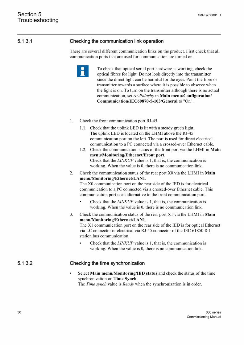
To check that optical serial port hardware is working, check theoptical fibres for light. Do not look directly into the transmittersince the direct light can be harmful for the eyes. Point the fibre ortransmitter towards a surface where it is possible to observe whenthe light is on. To turn on the transmitter although there is no actualcommunication, set revPolarity in Main menu/Configuration/Communication/IEC60870-5-103/General to "On".
1. Check the front communication port RJ-45.1.1. Check that the uplink LED is lit with a steady green light.
The uplink LED is located on the LHMI above the RJ-45communication port on the left. The port is used for direct electricalcommunication to a PC connected via a crossed-over Ethernet cable.
1.2. Check the communication status of the front port via the LHMI in Mainmenu/Monitoring/Ethernet/Front port.Check that the LINKUP value is 1, that is, the communication isworking. When the value is 0, there is no communication link.
2. Check the communication status of the rear port X0 via the LHMI in Mainmenu/Monitoring/Ethernet/LAN1.The X0 communication port on the rear side of the IED is for electricalcommunication to a PC connected via a crossed-over Ethernet cable. Thiscommunication port is an alternative to the front communication port.• Check that the LINKUP value is 1, that is, the communication is
working. When the value is 0, there is no communication link.3. Check the communication status of the rear port X1 via the LHMI in Main
menu/Monitoring/Ethernet/LAN1.The X1 communication port on the rear side of the IED is for optical Ethernetvia LC connector or electrical via RJ-45 connector of the IEC 61850-8-1station bus communication.• Check that the LINKUP value is 1, that is, the communication is
working. When the value is 0, there is no communication link.
5.1.3.2 Checking the time synchronization
• Select Main menu/Monitoring/IED status and check the status of the timesynchronization on Time Synch.The Time synch value is Ready when the synchronization is in order.
Section 5 1MRS756801 DTroubleshooting
30 630 seriesCommissioning Manual

Activate the time synchronization source. Otherwise, the valueis always Ready.
5.1.4 Running the display testTo run the display test, either use the push buttons or start the test via the menu.
• Select Main menu/Test/LED test.• Press or simultaneously and .
All the LEDs are tested by turning them on simultaneously. The display showsa set of patterns so that all the pixels are activated. After the test, the displayreturns to normal state.
5.2 Indication messages
5.2.1 Internal faultsWhen the Ready LED indicates an internal fault by flashing, the messageassociated with the fault is found in the internal event list in the LHMI menu Mainmenu/Monitoring/Internal events. The message includes the date, time,description and signal state for the fault. The internal event list is not updateddynamically. The list is updated by leaving the Internal events menu and thenselecting it again. The current status of the internal fault signals can also bechecked via the LHMI in Main menu/Monitoring/IED status.
The ABB logo together with the IED FAILURE message appear on the screenafter a five minutes' communication break between the LHMI and the IED. TheLHMI panel displays the message due to a communication failure or a severefunctional error in the IED. The protection functionality of the device can beensured by testing the IRF contact status.
Different actions are taken depending on the severity of the fault. If the fault isfound to be permanent, the IED stays in internal fault mode. The IED continues toperform internal tests during the fault situation.
When a fault appears, the fault indication message is to be recorded and statedwhen requesting support or service.
1MRS756801 D Section 5Troubleshooting
630 series 31Commissioning Manual
Table 5: Internal fault indications
Fault indication Additional informationInternal FaultReal Time Clock Error
Hardware error with the real time clock.
Internal FaultRuntime Exec. Error
One or more of the application threadsare not working properly.
Internal FaultSW Watchdog Error
This signal will be activated when theterminal has been under too heavyload for at least 5 minutes.
Internal FaultRuntime App Error
One or more of the application threadsare not in an expected state.
Internal FaultFile System Error
A file system error has occurred.
Internal FaultTRM-Error
A TRM card error has occurred. Theinstance number is displayed at theend of the fault indication.
Internal FaultCOM-Error
A COM card error has occurred. Theinstance number is displayed at theend of the fault indication.
Internal FaultPSM-Error
A PSM card error has occurred. Theinstance number is displayed at theend of the fault indication.
Internal FaultRTD Error
An RTD card error has occurred. Theinstance number is displayed at theend of the fault indication.
5.2.2 WarningsThe warning message associated with the fault is found in the internal event list inthe LHMI menu Main menu/Monitoring/Internal events. The message includesthe date, time, description and signal state for the fault. The current status of theinternal fault signals can also be checked via the LHMI in Main menu/Monitoring/IED status.
When a fault appears, record the fault indication message and state it whenordering service.
Table 6: Warning indications
Warning indication DescriptionWarningIEC 61850 Error
IEC 61850 has not succeeded in some actionssuch as reading the configuration file or startup.
WarningDNP3 Error
Error in DNP3 communication
5.2.3 Additional indicationsThe additional indication messages do not activate internal fault or warning.
Section 5 1MRS756801 DTroubleshooting
32 630 seriesCommissioning Manual

The messages are listed in the LHMI menu under the event list. The signal statusdata is found under the IED status and in the internal event list.
Table 7: Additional indications
Warning indication Additional informationTime Synch Error Source of the time synchronization is lost or time
system has made a time reset.
BATTERY1 Error Auxiliary power is disconnected.
Settings Changed Settings have been changed.
Setting Groups Changed Setting group has been changed.
5.3 Correction procedures
5.3.1 Factory settings restorationIn case of configuration data loss or error that prevents the IED from workingproperly, the configuration can be restored to the original factory state. All defaultsettings and configuration files stored in the factory are restored.
For further information on restoring factory settings, contact customer support.
5.3.2 Changing and setting the passwordThe password can only be set with PCM600.
For more information, see PCM600 documentation.
5.3.3 Identifying IED application problemsNavigate to the appropriate menu in the LHMI to identify possible problems.
• Check that the function is on.• Check that the correct setting group (1 to 4) is activated.• Check the blocking.• Check the mode.• Check the measurement value.• Check the connection to trip and disturbance recorder functions.• Check the channel settings.
1MRS756801 D Section 5Troubleshooting
630 series 33Commissioning Manual

5.3.3.1 Inspecting the wiring
The physical inspection of wiring connections often reveals the wrong connectionfor phase currents or voltages. Even when the phase current or voltage connectionsto IED terminals are correct, wrong polarity of one or more measurementtransformers can cause problems.
• Check the current or voltage measurements and their phase information fromMain menu/Measurements.
• Check that the phase information and phase shift between phases is correct.• Correct the wiring if needed.
• Change the parameter ReversePolarity in Configuration/I/O modules/AIM2 for the channel n (n= the number of the channel that has wrongpolarity).
• In PCM600, change the parameter CTStarPointn (n= the number on thecurrent input) under the parameter settings for each current input.
• Check the actual state of the connected binary inputs.• In LHMI, select Main menu/Monitoring/I/O status/Binary input
modules. Then navigate to the board with the actual binary input to bechecked.
• With PCM600, right-click the product and select Signal Monitoring.Then navigate to the actual I/O board and to the binary input in question.The activated input signal is indicated with a yellow-lit diode.
• Measure output contacts using the voltage drop method of applying at least theminimum contact load given for the output relays in the technical data, forexample, 100 mA at 24 V AC/DC.
Output relays, especially power output relays, are designed forbreaking high currents. Due to this, layers of high resistancemay appear on the surface of the contacts. Do not determineproper functionality of connectivity or contact resistance bymeasuring with a regular hand-held ohm meter.
Section 5 1MRS756801 DTroubleshooting
34 630 seriesCommissioning Manual

A1
2
3
4
V
GUID-BBAEAF55-8D01-4711-A71D-BBC76B60BA3D V1 EN
Figure 2: Testing output contacts using the voltage drop method
1 Contact current
2 Contact voltage drop
3 Load
4 Supply voltage
1MRS756801 D Section 5Troubleshooting
630 series 35Commissioning Manual

V1
2
A
GUID-31DF5495-91F1-4A4B-8FD5-50625038961E V1 EN
Figure 3: Testing a trip contact
1 Trip contact under test
2 Current limiting resistor
• To check the status of the output circuits driving the output relay via theLHMI, select Main menu/Monitoring/I/O status/Binary output modulesand then navigate to the board with the actual binary output to be checked.
• Test and change the relay state manually.1. To set the IED to test mode, select Main menu/Test/IED test mode/
TestMode and set the parameter to ”On”.2. To operate or force the output relay to operate, select Main menu/Test/
Forcing/Binary output values and then navigate to the board with theactual binary output relay to be operated/forced.
3. Select the BOn_PO to be operated or forced and press and or to operate the actual output relay.In PCM600, only the result of these operations can be checked by right-clicking the product and selecting Signal Monitoring and then navigating
Section 5 1MRS756801 DTroubleshooting
36 630 seriesCommissioning Manual
to the actual I/O-board and the binary input in question. The activatedoutput signal is indicated with a yellow-lit diode. Each BOn_PO isrepresented by two signals. The first signal in LHMI is the actual value“1” or “0” of the output, and in PCM600 a lit or dimmed diode. Thesecond signal is the status Normal or Forced. Forced status is onlyachieved when the BO is set to “Forced” or operated on the LHMI.
Set the parameter TestMode to “Off” after completingthese tests. The Start LED stops flashing when the relayis no longer in test mode.
An initially high contact resistance does not cause problems as it is reduced quicklyby the electrical cleaning effect of fritting and thermal destruction of layers,bringing the contact resistance back to the mOhm range. As a result, practically thefull voltage is available at the load.
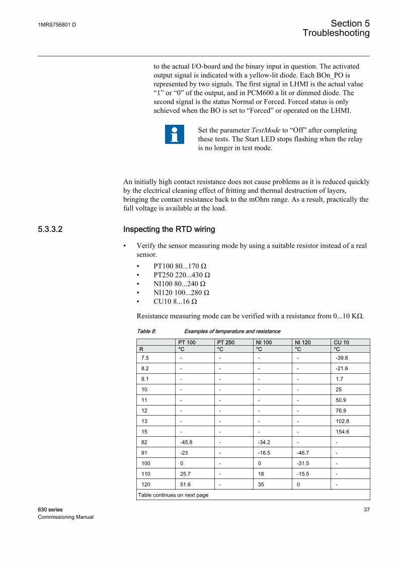
5.3.3.2 Inspecting the RTD wiring
• Verify the sensor measuring mode by using a suitable resistor instead of a realsensor.• PT100 80...170 Ω• PT250 220...430 Ω• NI100 80...240 Ω• NI120 100...280 Ω• CU10 8...16 Ω
Resistance measuring mode can be verified with a resistance from 0...10 KΩ.
Table 8: Examples of temperature and resistance
PT 100 PT 250 NI 100 NI 120 CU 10R °C °C °C °C °C7.5 - - - - -39.8
8.2 - - - - -21.6
9.1 - - - - 1.7
10 - - - - 25
11 - - - - 50.9
12 - - - - 76.9
13 - - - - 102.8
15 - - - - 154.6
82 -45.8 - -34.2 - -
91 -23 - -16.5 -46.7 -
100 0 - 0 -31.5 -
110 25.7 - 18 -15.5 -
120 51.6 - 35 0 -
Table continues on next page
1MRS756801 D Section 5Troubleshooting
630 series 37Commissioning Manual

PT 100 PT 250 NI 100 NI 120 CU 10R °C °C °C °C °C150 130.5 - 82.6 43.3 -
160 157.2 - 97.5 56.8 -
180 - - 125.5 84 -
200 - -50.8 151.8 107 -
220 - -30.6 176.3 130 -
240 - -10.2 199.3 151.8 -
270 - 20.5 - 182.2 -
300 - 51.6 - -
330 - 82.9 - -
360 - 114.6 - -
390 - 146.5 - -
430 - 189.6 - -
RTD connector numbering is an example of a 4U case. See thetechnical manual for complete terminal diagrams.
GUID-327C519C-BA13-4161-A62C-B94074ECEC01 V1 EN
Figure 4: Testing sensor/resistance input by connecting resistor directlyto connector
Voltage type measurement mode can be verified by connecting a voltagesource on the input and measure input voltage at the same time by multimeter,for example, 5 VDC voltage.
Section 5 1MRS756801 DTroubleshooting
38 630 seriesCommissioning Manual

GUID-A1C53A59-D607-4E0D-B3BF-7E12BEA35E9A V1 EN
Figure 5: Testing voltage input by connecting voltage source directly toconnector and measuring input voltage by multimeter
GUID-DC08299A-C531-4C02-9273-AA9BD6ED7F6E V1 EN
Figure 6: Testing current input by connecting voltage source directly toconnector and measuring input current by multimeter
Current type measurement mode can be verified by connecting a voltagesource on the input, for example, 1 V DC.
• Verify milliampere ouputs by connecting a multimeter to mA output.
1MRS756801 D Section 5Troubleshooting
630 series 39Commissioning Manual

GUID-E486DBB7-EB19-436C-9294-90B8B5FF398D V1 EN
Figure 7: Testing mA output by connecting multimeter directly toconnector and measuring output current by multimeter
• Check the status of the output circuits driving the mA outputs via the LHMI.Select Main menu/Monitoring/I/O status/mA output modules/RTD3 andcheck the output status and value for the channel under inspection.
• Test and change the output manually.1. Select Main menu/Test/IED test mode/TestMode and set the
parameter to “On”.2. Select Main menu/Tests/Forcing/Analog output values/RTD3.3. Select the AOn to be forced.4. Force the actual output using and or .
Each AOn is represented by two signals. The first signal in LHMI is the actualprimary value of the output. The second signal is the status Normal or Forced.Forced status is only achieved when the AO is set to “Forced” on the LHMI.
When forcing analog output signals the scaling defined byanalog output channel configuration is not used. Fixed scalingfactor 1000:1 is used instead. This means that forcing value5.000 A is seen as 5 mA when measured from output.
Do not force or send values to disconnected channels. Thisresults in an out-of-range error.
Forcing feature can be tested only for configured outputchannels. When mA current values are forced to non-configured output channels, values are not passed to mA outputchannel HW circuitry.
Section 5 1MRS756801 DTroubleshooting
40 630 seriesCommissioning Manual

Set the parameter TestMode to”Off” after completing the tests.The Start LED stops flashing when the relay is no longer in testmode.
1MRS756801 D Section 5Troubleshooting
630 series 41Commissioning Manual

42

Section 6 Glossary
AC Alternating currentCAT 5 A twisted pair cable type designed for high signal integrityCT Current transformerDC 1. Direct current
2. Disconnector3. Double command
DHCP Dynamic Host Configuration ProtocolEMC Electromagnetic compatibilityEthernet A standard for connecting a family of frame-based computer
networking technologies into a LANFAT Factory acceptance testingHMI Human-machine interfaceHW HardwareI/O Input/outputIEC International Electrotechnical CommissionIED Intelligent electronic deviceIET600 Integrated Engineering ToolboxIP Internet protocolIP address A set of four numbers between 0 and 255, separated by
periods. Each server connected to the Internet is assigned aunique IP address that specifies the location for the TCP/IPprotocol.
IRF 1. Internal fault2. Internal relay fault
LAN Local area networkLC Connector type for glass fibre cableLCD Liquid crystal displayLED Light-emitting diodeLHMI Local human-machine interfaceNCC Network control centerPC 1. Personal computer
2. Polycarbonate
1MRS756801 D Section 6Glossary
630 series 43Commissioning Manual

PCM600 Protection and Control IED ManagerRJ-45 Galvanic connector typeRTD Resistance temperature detectorRx Receive/ReceivedSAT Site acceptance testingTCP/IP Transmission Control Protocol/Internet ProtocolTx Transmit/TransmittedVT Voltage transformerWAN Wide area networkWHMI Web human-machine interface
Section 6 1MRS756801 DGlossary
44 630 seriesCommissioning Manual

45


Contact us
ABB OyMedium Voltage Products,Distribution AutomationP.O. Box 699FI-65101 VAASA, FinlandPhone +358 10 22 11Fax +358 10 22 41094
www.abb.com/substationautomation
1MR
S75
6801
D©
Cop
yrig
ht 2
014
AB
B. A
ll rig
hts
rese
rved
.