Embed Size (px)
Citation preview

Relion® 650 series
Transformer protection RET650 ANSICommissioning Manual


Document ID: 1MRK 504 130-UUSIssued: June 2012
Revision: AProduct version: 1.2
© Copyright 2012 ABB. All rights reserved

CopyrightThis document and parts thereof must not be reproduced or copied without writtenpermission from ABB, and the contents thereof must not be imparted to a third party,nor used for any unauthorized purpose.
The software and hardware described in this document is furnished under a license andmay be used or disclosed only in accordance with the terms of such license.
TrademarksABB and Relion are registered trademarks of the ABB Group. All other brand orproduct names mentioned in this document may be trademarks or registeredtrademarks of their respective holders.
WarrantyPlease inquire about the terms of warranty from your nearest ABB representative.
ABB Inc.
1021 Main Campus Drive
Raleigh, NC 27606, USA
Toll Free: 1-800-HELP-365, menu option #8
ABB Inc.
3450 Harvester Road
Burlington, ON L7N 3W5, Canada
Toll Free: 1-800-HELP-365, menu option #8
ABB Mexico S.A. de C.V.
Paseo de las Americas No. 31 Lomas Verdes 3a secc.
53125, Naucalpan, Estado De Mexico, MEXICO
Phone: (+1) 440-585-7804, menu option #8

ConformityThis product complies with the directive of the Council of the European Communitieson the approximation of the laws of the Member States relating to electromagneticcompatibility (EMC Directive 2004/108/EC) and concerning electrical equipment foruse within specified voltage limits (Low-voltage directive 2006/95/EC). Thisconformity is the result of tests conducted by ABB in accordance with the productstandards EN 50263 and EN 60255-26 for the EMC directive, and with the productstandards EN 60255-1 and EN 60255-27 for the low voltage directive. The product isdesigned in accordance with the international standards of the IEC 60255 series andANSI C37.90. The DNP protocol implementation in the IED conforms to "DNP3Intelligent Electronic Device (IED) Certification Procedure Subset Level 2", availableat www.dnp.org .

DisclaimerThe data, examples and diagrams in this manual are included solely for the concept orproduct description and are not to be deemed as a statement of guaranteed properties.All persons responsible for applying the equipment addressed in this manual mustsatisfy themselves that each intended application is suitable and acceptable, includingthat any applicable safety or other operational requirements are complied with. Inparticular, any risks in applications where a system failure and/or product failure wouldcreate a risk for harm to property or persons (including but not limited to personalinjuries or death) shall be the sole responsibility of the person or entity applying theequipment, and those so responsible are hereby requested to ensure that all measuresare taken to exclude or mitigate such risks.
This document has been carefully checked by ABB but deviations cannot becompletely ruled out. In case any errors are detected, the reader is kindly requested tonotify the manufacturer. Other than under explicit contractual commitments, in noevent shall ABB be responsible or liable for any loss or damage resulting from the useof this manual or the application of the equipment.

Safety information
Dangerous voltages can occur on the connectors, even though theauxiliary voltage has been disconnected.
Non-observance can result in death, personal injury or substantialproperty damage.
Only a competent electrician is allowed to carry out the electricalinstallation.
National and local electrical safety regulations must always be followed.
The frame of the IED has to be carefully grounded.
Whenever changes are made in the IED, measures should be taken toavoid inadvertent tripping.
The IED contains components which are sensitive to electrostaticdischarge. Unnecessary touching of electronic components musttherefore be avoided.


Table of contents
Section 1 Introduction............................................................................7This manual..............................................................................................7Intended audience....................................................................................7Product documentation.............................................................................8
Product documentation set..................................................................8Document revision history...................................................................9Related documents............................................................................10
Symbols and conventions.......................................................................10Symbols.............................................................................................10Document conventions......................................................................11
Section 2 Available functions..............................................................13Main protection functions........................................................................13Back-up protection functions..................................................................13Control and monitoring functions............................................................15Communication.......................................................................................18Basic IED functions.................................................................................19
Section 3 Starting up...........................................................................21Factory and site acceptance testing.......................................................21Commissioning checklist........................................................................21Checking the power supply.....................................................................22Energizing the IED..................................................................................22
Checking the IED operation...............................................................22IED start-up sequence.......................................................................22
Setting up communication between PCM600 and the IED.....................23Writing an application configuration to the IED.......................................28Checking CT circuits...............................................................................29Checking VT circuits...............................................................................30Checking the RTXP test switch .............................................................30Checking binary input and output circuits...............................................31
Binary input circuits............................................................................31Binary output circuits.........................................................................31
Checking optical connections.................................................................31
Section 4 Establishing connection and verifying the IEC 61850station communication.........................................................33
Table of contents
1Commissioning Manual

Setting the station communication..........................................................33Verifying the communication...................................................................33
Section 5 Testing IED operation..........................................................35Preparing the IED to verify settings........................................................35Activating test mode...............................................................................37Preparing the connection to the test equipment.....................................37Connecting the test equipment to the IED..............................................38Releasing the function to be tested........................................................39Verifying analog primary and secondary measurement.........................40Testing protection functionality...............................................................41
Section 6 Testing functionality.............................................................43Testing disturbance report......................................................................43
Introduction........................................................................................43Disturbance report settings................................................................43
Identifying the function to test in the technical reference manual ..........43Testing differential protection functions..................................................44
Transformer differential protection T2WPDIF (87T) andT3WPDIF (87T)(87T).........................................................................44
Verifying the settings....................................................................44Completing the test.......................................................................45
Restricted earth fault protection, low impedance REFPDIF(87N)..................................................................................................45
Verifying the settings....................................................................46Completing the test.......................................................................46
High impedance differential protection HZPDIF (87).........................46Verifying the settings....................................................................47Completing the test.......................................................................48
Testing current protection functions........................................................48Instantaneous phase overcurrent protection 3-phase outputPHPIOC (50)......................................................................................48
Measuring the operate limit of set values.....................................48Completing the test.......................................................................49
Four step phase overcurrent protection 3-phase outputOC4PTOC (51_67)............................................................................49
Verifying the settings....................................................................49Completing the test.......................................................................50
Instantaneous residual overcurrent protection EFPIOC (50N)..........50Measuring the operate limit of set values.....................................51Completing the test.......................................................................51
Table of contents
2Commissioning Manual

Four step residual overcurrent protection, zero or negativesequence direction EF4PTOC (51N/67N).........................................51
Four step directional residual overcurrent protection ..................51Four step non-directional residual overcurrent protection............52Completing the test.......................................................................52
Thermal overload protection, two time constants TRPTTR (49).......53Checking operate and reset values..............................................53Completing the test.......................................................................54
Breaker failure protection, phase segregated activation andoutput CCRBRF (50BF).....................................................................54
Checking the phase current operate value, Pickup_PH...............55Checking the residual (ground fault) current operate valuePickup_N set below Pickup_PH....................................................55Checking the re-trip and back-up times........................................55Verifying the re-trip mode.............................................................56Verifying the back-up trip mode....................................................56Verifying the case RetripMode = Contact.....................................58Verifying the function mode Current&Contact..............................58Completing the test.......................................................................59
Pole discrepancy protection CCRPLD (52PD)..................................59Verifying the settings....................................................................59Completing the test.......................................................................60
Directional underpower protection GUPPDUP (37)...........................60Verifying the settings....................................................................60Completing the test.......................................................................62
Directional overpower protection GOPPDOP (32)............................62Verifying the settings....................................................................62Completing the test.......................................................................63
Testing voltage protection functions.......................................................63Two step undervoltage protection UV2PTUV (27)............................63
Verifying the setting......................................................................64Completing the test.......................................................................64
Two step overvoltage protection OV2PTOV (59)..............................64Verifying the settings....................................................................65Completing the test.......................................................................65
Two step residual overvoltage protection ROV2PTOV (59N)...........65Verifying the settings....................................................................65Completing the test.......................................................................66
Overexcitation protection OEXPVPH (24).........................................66Verifying the settings....................................................................66
Table of contents
3Commissioning Manual

Completing the test.......................................................................67Testing frequency protection functions...................................................67
Underfrequency protection SAPTUF (81)..........................................67Verifying the settings....................................................................67Completing the test.......................................................................68
Overfrequency protection SAPTOF (81)...........................................68Verifying the settings....................................................................68Completing the test.......................................................................69
Rate-of-change frequency protection SAPFRC (81).........................69Verifying the settings....................................................................70Completing the test.......................................................................70
Testing control functions.........................................................................70Voltage control...................................................................................71
Secondary test..............................................................................73Check the activation of the voltage control operation...................73Check the normal voltage regulation function..............................74Check the undervoltage block function.........................................74Check the upper and lower busbar voltage limit...........................75Check the overcurrent block function...........................................75Automatic voltage control for tap changer, parallel controlTR8ATCC.....................................................................................76Completing the test.......................................................................80
Testing logic functions............................................................................80Tripping logic, common 3-phase output SMPPTRC (94)..................80
Three-phase operating mode.......................................................80Circuit breaker lockout..................................................................81Completing the test.......................................................................81
Testing monitoring functions...................................................................81Event counter CNTGGIO...................................................................81
Testing metering functions......................................................................82Pulse counter PCGGIO.....................................................................82
Exit test mode.........................................................................................82
Section 7 Commissioning and maintenance of the faultclearing system...................................................................83Commissioning and maintenance of the fault clearing system...............83
Commissioning tests..........................................................................83Periodic maintenance tests...............................................................83
Visual inspection...........................................................................84Maintenance tests........................................................................84
Table of contents
4Commissioning Manual

Section 8 Troubleshooting ..................................................................89Fault tracing............................................................................................89
Identifying hardware errors................................................................89Identifying runtime errors...................................................................89Identifying communication errors.......................................................89
Checking the communication link operation.................................90Checking the time synchronization...............................................90
Running the display test....................................................................91Indication messages...............................................................................91
Internal faults.....................................................................................91Warnings............................................................................................92Additional indications.........................................................................93
Correction procedures............................................................................93Changing and setting the password..................................................93Identifying IED application problems.................................................93
Inspecting the wiring.....................................................................94
Section 9 Glossary..............................................................................99
Table of contents
5Commissioning Manual

6

Section 1 Introduction
1.1 This manual
The commissioning manual contains instructions on how to commission the IED. Themanual can also be used by system engineers and maintenance personnel for assistanceduring the testing phase. The manual provides procedures for checking of externalcircuitry and energizing the IED, parameter setting and configuration as well asverifying settings by secondary injection. The manual describes the process of testingan IED in a substation which is not in service. The chapters are organized inchronological order in which the IED should be commissioned.
1.2 Intended audience
This manual addresses the personnel responsible for commissioning, maintenance andtaking the IED in and out of normal service.
The commissioning personnel must have a basic knowledge of handling electronicequipment. The commissioning and maintenance personnel must be well experiencedin using protection equipment, test equipment, protection functions and the configuredfunctional logics in the IED.
1MRK 504 130-UUS A Section 1Introduction
7Commissioning Manual

1.3 Product documentation
1.3.1 Product documentation set
Pla
nnin
g &
pur
chas
e
Eng
inee
ring
Inst
allin
g
Com
mis
sion
ing
Ope
ratio
n
Mai
nten
ance
Dec
omm
issi
onin
gde
inst
allin
g&
dis
posa
l
Application manual
Operation manual
Installation manual
Service manual
Engineering manual
Commissioning manual
Communication protocolmanual
Technical manual
Pla
nnin
g &
pur
chas
e
Eng
inee
ring
Inst
allin
g
Com
mis
sion
ing
Ope
ratio
n
Mai
nten
ance
Dec
omm
issi
onin
gde
inst
allin
g&
dis
posa
l
Pla
nnin
g &
pur
chas
e
Eng
inee
ring
Inst
allin
g
Com
mis
sion
ing
Ope
ratio
n
Mai
nten
ance
Dec
omm
issi
onin
gde
inst
allin
g&
dis
posa
l
Application manualApplication manual
Operation manualOperation manual
Installation manualInstallation manual
Service manualService manual
Engineering manualEngineering manual
Commissioning manualCommissioning manual
Communication protocolmanualCommunication protocolmanual
Technical manualTechnical manual
en07000220.vsd
IEC07000220 V1 EN
Figure 1: The intended use of manuals in different lifecycles
The engineering manual contains instructions on how to engineer the IEDs using thedifferent tools in PCM600. The manual provides instructions on how to set up aPCM600 project and insert IEDs to the project structure. The manual also recommendsa sequence for engineering of protection and control functions, LHMI functions as wellas communication engineering for IEC 60870-5-103, IEC 61850 and DNP3.
The installation manual contains instructions on how to install the IED. The manualprovides procedures for mechanical and electrical installation. The chapters areorganized in chronological order in which the IED should be installed.
The commissioning manual contains instructions on how to commission the IED. Themanual can also be used by system engineers and maintenance personnel for assistance
Section 1 1MRK 504 130-UUS AIntroduction
8Commissioning Manual
during the testing phase. The manual provides procedures for checking of externalcircuitry and energizing the IED, parameter setting and configuration as well asverifying settings by secondary injection. The manual describes the process of testingan IED in a substation which is not in service. The chapters are organized inchronological order in which the IED should be commissioned.
The operation manual contains instructions on how to operate the IED once it has beencommissioned. The manual provides instructions for monitoring, controlling andsetting the IED. The manual also describes how to identify disturbances and how toview calculated and measured power grid data to determine the cause of a fault.
The service manual contains instructions on how to service and maintain the IED. Themanual also provides procedures for de-energizing, de-commissioning and disposal ofthe IED.
The application manual contains application descriptions and setting guidelines sortedper function. The manual can be used to find out when and for what purpose a typicalprotection function can be used. The manual can also be used when calculating settings.
The technical manual contains application and functionality descriptions and listsfunction blocks, logic diagrams, input and output signals, setting parameters andtechnical data sorted per function. The manual can be used as a technical referenceduring the engineering phase, installation and commissioning phase, and during normalservice.
The communication protocol manual describes a communication protocol supported bythe IED. The manual concentrates on vendor-specific implementations.
The point list manual describes the outlook and properties of the data points specific tothe IED. The manual should be used in conjunction with the correspondingcommunication protocol manual.
1.3.2 Document revision historyDocument revision/date History-/March 2012 First release
A/June 2012 Minor corrections made
1MRK 504 130-UUS A Section 1Introduction
9Commissioning Manual

1.3.3 Related documentsDocuments related to RET650 Identity numberApplication manual 1MRK 504 128-UUS
Technical manual 1MRK 504 129-UUS
Commissioning manual 1MRK 504 130-UUS
Product Guide, configured 1MRK 504 131-BUS
Type test certificate 1MRK 504 131-TUS
Application notes for Circuit Breaker Control 1MRG006806
650 series manuals Identity numberCommunication protocol manual, DNP3 1MRK 511 257-UUS
Communication protocol manual, IEC 61850–8–1 1MRK 511 258-UUS
Communication protocol manual, IEC 60870-5-103 1MRK 511 259-UUS
Cyber Security deployment guidelines 1MRK 511 268-UUS
Point list manual, DNP3 1MRK 511 260-UUS
Engineering manual 1MRK 511 261-UUS
Operation manual 1MRK 500 095-UUS
Installation manual 1MRK 514 015-UUS
1.4 Symbols and conventions
1.4.1 Symbols
The electrical warning icon indicates the presence of a hazard whichcould result in electrical shock.
The warning icon indicates the presence of a hazard which could resultin personal injury.
The caution icon indicates important information or warning related tothe concept discussed in the text. It might indicate the presence of ahazard which could result in corruption of software or damage toequipment or property.
Section 1 1MRK 504 130-UUS AIntroduction
10Commissioning Manual

The information icon alerts the reader of important facts and conditions.
The tip icon indicates advice on, for example, how to design yourproject or how to use a certain function.
Although warning hazards are related to personal injury, it is necessary to understandthat under certain operational conditions, operation of damaged equipment may resultin degraded process performance leading to personal injury or death. Therefore,comply fully with all warning and caution notices.
1.4.2 Document conventionsA particular convention may not be used in this manual.
• Abbreviations and acronyms in this manual are spelled out in the glossary. Theglossary also contains definitions of important terms.
• Push button navigation in the LHMI menu structure is presented by using the pushbutton icons.To navigate between the options, use and .
• HMI menu paths are presented in bold.Select Main menu/Settings.
• LHMI messages are shown in Courier font.To save the changes in non-volatile memory, select Yes and press .
• Parameter names are shown in italics.The function can be enabled and disabled with the Operation setting.
• The ^ character in front of an input or output signal name in the function blocksymbol given for a function, indicates that the user can set an own signal name inPCM600.
• The * character after an input or output signal name in the function block symbolgiven for a function, indicates that the signal must be connected to anotherfunction block in the application configuration to achieve a valid applicationconfiguration.
• Dimensions are provided both in inches and mm. If it is not specifically mentionedthen the dimension is in mm.
1MRK 504 130-UUS A Section 1Introduction
11Commissioning Manual

12

Section 2 Available functions
Note that not all functions included in the tables below havecommissioning information available.
2.1 Main protection functions
IEC 61850/Function blockname
ANSI Function description Transformer
RET
650
RET
650
(A01
A)2W
/1C
B
RET
650
(A05
A)3W
/1C
B
RET
650
(A07
A)O
LTC
Differential protection
T2WPDIF 87T Transformer differential protection, two winding 0–1 1
T3WPDIF 87T Transformer differential protection, three winding 0–1 1
REFPDIF 87N Restricted earth fault protection, low impedance 0–3 2 3
HZPDIF 87 1Ph High impedance differential protection 0–2 2 2
2.2 Back-up protection functions
IEC 61850/Function blockname
ANSI Function description Transformer
RET
650
RET
650
(A01
A)2W
/1C
B
RET
650
(A05
A)3W
/1C
B
RET
650
(A07
A)O
LTC
Current protection
PHPIOC 50 Instantaneous phase overcurrent protection, 3–phase output
0–3 2 3
OC4PTOC 51 Four step phase overcurrent protection, 3–phaseoutput
2 2
Table continues on next page
1MRK 504 130-UUS A Section 2Available functions
13Commissioning Manual

IEC 61850/Function blockname
ANSI Function description Transformer
RET
650
RET
650
(A01
A)2W
/1C
B
RET
650
(A05
A)3W
/1C
B
RET
650
(A07
A)O
LTC
OC4PTOC 51/67 Four step directional phase protection, 3–phaseoutput
0–3 3
EFPIOC 50N Instantaneous residual overcurrent protection 0–3 2 3
EF4PTOC 51N/67N Four step residual overcurrent protection, zero/negative sequence direction
0–3 2 3 2
TRPTTR 49 Thermal overload protection, two time constants 0–3 2 3 2
CCRBRF 50BF Breaker failure protection, 3–phase activation andoutput
0–3 2 3
CCRPLD 52PD Pole discordance protection 0–3 2 3
GUPPDUP 37 Directional underpower protection 0–2 1 1 2
GOPPDOP 32 Directional overpower protection 0–2 1 1 2
DNSPTOC 46 Negative sequence based overcurrent function 0–2 1 2
Voltage protection
UV2PTUV 27 Two step undervoltage protection 0–2 1 1 2
OV2PTOV 59 Two step overvoltage protection 0–2 1 1 2
ROV2PTOV 59N Two step residual overvoltage protection 0–2 1 1 2
OEXPVPH 24 Overexcitation protection 0–1 1 1
Frequency protection
SAPTUF 81 Underfrequency function 0–4 4 4 4
SAPTOF 81 Overfrequency function 0–4 4 4 4
SAPFRC 81 Rate-of-change frequency protection 0–4 2 2 4
Section 2 1MRK 504 130-UUS AAvailable functions
14Commissioning Manual

2.3 Control and monitoring functions
IEC 61850/Functionblock name
ANSI Function description Transformer
RET
650
RET
650
(A01
A)2W
/1C
B
RET
650
(A05
A)3W
/1C
B
RET
650
(A07
A)O
LTC
Control
QCBAY Bay control 1 1 1 1
LOCREM Handling of LR-switch positions 1 1 1 1
LOCREMCTRL LHMI control of Permitted Source To Operate(PSTO)
1 1 1 1
CBC2 Circuit breaker for 2CB 0–1 1
CBC3 Circuit breaker for 3CB 0–1 1
CBC4 Circuit breaker for 4CB 0–1 1
TR8ATCC 90 Automatic voltage control for tap changer,parallel control
0–2 1 1 2
TCMYLTC 84 Tap changer control and supervision, 6 binaryinputs
0–2 1 1 2
SLGGIO Logic Rotating Switch for function selection andLHMI presentation
15 15 15 15
VSGGIO Selector mini switch extension 20 20 20 20
DPGGIO IEC 61850 generic communication I/O functionsdouble point
16 16 16 16
SPC8GGIO Single point generic control 8 signals 5 5 5 5
AUTOBITS AutomationBits, command function for DNP3.0 3 3 3 3
I103CMD Function commands for IEC60870-5-103 1 1 1 1
I103IEDCMD IED commands for IEC60870-5-103 1 1 1 1
I103USRCMD Function commands user defined forIEC60870-5-103
4 4 4 4
I103GENCMD Function commands generic for IEC60870-5-103 50 50 50 50
I103POSCMD IED commands with position and select forIEC60870-5-103
50 50 50 50
Secondary system supervision
TCSSCBR Breaker close/trip circuit monitoring 3 3 3 3
Logic
SMPPTRC 94 Tripping logic, common 3–phase output 1–3 2 3 2
TMAGGIO Trip matrix logic 12 12 12 12
OR Configurable logic blocks, OR gate 283 283 283 283
Table continues on next page
1MRK 504 130-UUS A Section 2Available functions
15Commissioning Manual

IEC 61850/Functionblock name
ANSI Function description Transformer
RET
650
RET
650
(A01
A)2W
/1C
B
RET
650
(A05
A)3W
/1C
B
RET
650
(A07
A)O
LTC
INVERTER Configurable logic blocks, Inverter gate 140 140 140 140
PULSETIMER Configurable logic blocks, Pulse timer 40 40 40 40
GATE Configurable logic blocks, Controllable gate 40 40 40 40
XOR Configurable logic blocks, exclusive OR gate 40 40 40 40
LOOPDELAY Configurable logic blocks, loop delay 40 40 40 40
TIMERSET Configurable logic blocks, timer function block 40 40 40 40
AND Configurable logic blocks, AND gate 280 280 280 280
SRMEMORY Configurable logic blocks, set-reset memory flip-flop gate
40 40 40 40
RSMEMORY Configurable logic blocks, reset-set memory flip-flop gate
40 40 40 40
FXDSIGN Fixed signal function block 1 1 1 1
B16I Boolean 16 to Integer conversion 16 16 16 16
B16IFCVI Boolean 16 to Integer conversion with logic noderepresentation
16 16 16 16
IB16A Integer to Boolean 16 conversion 16 16 16 16
IB16FCVB Integer to Boolean 16 conversion with logic noderepresentation
16 16 16 16
Monitoring
CVMMXN Measurements 6 6 6 6
CMMXU Phase current measurement 10 10 10 10
VMMXU Phase-phase voltage measurement 6 6 6 6
CMSQI Current sequence component measurement 6 6 6 6
VMSQI Voltage sequence measurement 6 6 6 6
VNMMXU Phase-neutral voltage measurement 6 6 6 6
AISVBAS Function block for service values presentation ofthe analog inputs
1 1 1 1
TM_P_P2 Function block for service values presentation ofprimary analog inputs 600TRM
1 1 1 1
AM_P_P4 Function block for service values presentation ofprimary analog inputs 600AIM
1 1 1 1
TM_S_P2 Function block for service values presentation ofsecondary analog inputs 600TRM
1 1 1 1
AM_S_P4 Function block for service values presentation ofsecondary analog inputs 600AIM
1 1 1 1
Table continues on next page
Section 2 1MRK 504 130-UUS AAvailable functions
16Commissioning Manual

IEC 61850/Functionblock name
ANSI Function description Transformer
RET
650
RET
650
(A01
A)2W
/1C
B
RET
650
(A05
A)3W
/1C
B
RET
650
(A07
A)O
LTC
CNTGGIO Event counter 5 5 5 5
DRPRDRE Disturbance report 1 1 1 1
AxRADR Analog input signals 4 4 4 4
BxRBDR Binary input signals 6 6 6 6
SPGGIO IEC 61850 generic communication I/O functions 64 64 64 64
SP16GGIO IEC 61850 generic communication I/O functions16 inputs
16 16 16 16
MVGGIO IEC 61850 generic communication I/O functions 16 16 16 16
MVEXP Measured value expander block 66 66 66 66
SPVNZBAT Station battery supervision 0–1 1 1 1
SSIMG 63 Insulation gas monitoring function 0–2 2 2 2
SSIML 71 Insulation liquid monitoring function 0–2 2 2 2
SSCBR Circuit breaker condition monitoring 0–3 2 3 2
I103MEAS Measurands for IEC60870-5-103 1 1 1 1
I103MEASUSR Measurands user defined signals forIEC60870-5-103
3 3 3 3
I103AR Function status auto-recloser for IEC60870-5-103 1 1 1 1
I103EF Function status ground-fault for IEC60870-5-103 1 1 1 1
I103FLTPROT Function status fault protection forIEC60870-5-103
1 1 1 1
I103IED IED status for IEC60870-5-103 1 1 1 1
I103SUPERV Supervison status for IEC60870-5-103 1 1 1 1
I103USRDEF Status for user defined signals forIEC60870-5-103
20 20 20 20
Metering
PCGGIO Pulse counter logic 16 16 16 16
ETPMMTR Function for energy calculation and demandhandling
3 3 3 3
1MRK 504 130-UUS A Section 2Available functions
17Commissioning Manual
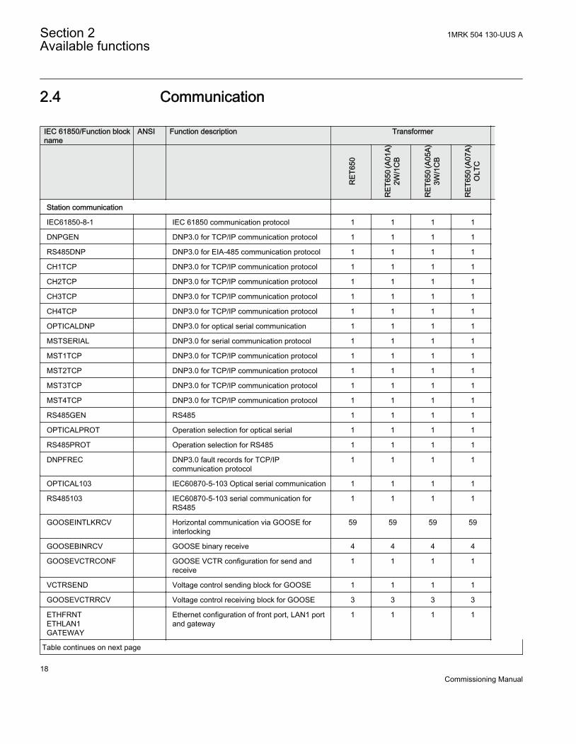
2.4 Communication
IEC 61850/Function blockname
ANSI Function description Transformer
RET
650
RET
650
(A01
A)2W
/1C
B
RET
650
(A05
A)3W
/1C
B
RET
650
(A07
A)O
LTC
Station communication
IEC61850-8-1 IEC 61850 communication protocol 1 1 1 1
DNPGEN DNP3.0 for TCP/IP communication protocol 1 1 1 1
RS485DNP DNP3.0 for EIA-485 communication protocol 1 1 1 1
CH1TCP DNP3.0 for TCP/IP communication protocol 1 1 1 1
CH2TCP DNP3.0 for TCP/IP communication protocol 1 1 1 1
CH3TCP DNP3.0 for TCP/IP communication protocol 1 1 1 1
CH4TCP DNP3.0 for TCP/IP communication protocol 1 1 1 1
OPTICALDNP DNP3.0 for optical serial communication 1 1 1 1
MSTSERIAL DNP3.0 for serial communication protocol 1 1 1 1
MST1TCP DNP3.0 for TCP/IP communication protocol 1 1 1 1
MST2TCP DNP3.0 for TCP/IP communication protocol 1 1 1 1
MST3TCP DNP3.0 for TCP/IP communication protocol 1 1 1 1
MST4TCP DNP3.0 for TCP/IP communication protocol 1 1 1 1
RS485GEN RS485 1 1 1 1
OPTICALPROT Operation selection for optical serial 1 1 1 1
RS485PROT Operation selection for RS485 1 1 1 1
DNPFREC DNP3.0 fault records for TCP/IPcommunication protocol
1 1 1 1
OPTICAL103 IEC60870-5-103 Optical serial communication 1 1 1 1
RS485103 IEC60870-5-103 serial communication forRS485
1 1 1 1
GOOSEINTLKRCV Horizontal communication via GOOSE forinterlocking
59 59 59 59
GOOSEBINRCV GOOSE binary receive 4 4 4 4
GOOSEVCTRCONF GOOSE VCTR configuration for send andreceive
1 1 1 1
VCTRSEND Voltage control sending block for GOOSE 1 1 1 1
GOOSEVCTRRCV Voltage control receiving block for GOOSE 3 3 3 3
ETHFRNTETHLAN1GATEWAY
Ethernet configuration of front port, LAN1 portand gateway
1 1 1 1
Table continues on next page
Section 2 1MRK 504 130-UUS AAvailable functions
18Commissioning Manual

IEC 61850/Function blockname
ANSI Function description Transformer
RET
650
RET
650
(A01
A)2W
/1C
B
RET
650
(A05
A)3W
/1C
B
RET
650
(A07
A)O
LTC
GOOSEDPRCV GOOSE function block to receive a doublepoint value
32 32 32 32
GOOSEINTRCV GOOSE function block to receive an integervalue
32 32 32 32
GOOSEMVRCV GOOSE function block to receive ameasurand value
16 16 16 16
GOOSESPRCV GOOSE function block to receive a singlepoint value
64 64 64 64
2.5 Basic IED functions
IEC 61850/Functionblock name
Function description
Basic functions included in all products
INTERRSIG Self supervision with internal event list 1
SELFSUPEVLST Self supervision with internal event list 1
TIMESYNCHGEN Time synchronization 1
SNTP Time synchronization 1
DTSBEGIN, DTSEND,TIMEZONE
Time synchronization, daylight saving 1
IRIG-B Time synchronization 1
SETGRPS Setting group handling 1
ACTVGRP Parameter setting groups 1
TESTMODE Test mode functionality 1
CHNGLCK Change lock function 1
TERMINALID IED identifiers 1
PRODINF Product information 1
SYSTEMTIME System time 1
RUNTIME IED Runtime comp 1
PRIMVAL Primary system values 1
SMAI_20_1 -SMAI_20_12
Signal matrix for analog inputs 2
3PHSUM Summation block 3 phase 12
Table continues on next page
1MRK 504 130-UUS A Section 2Available functions
19Commissioning Manual

IEC 61850/Functionblock name
Function description
GBASVAL Global base values for settings 6
ATHSTAT Authority status 1
ATHCHCK Authority check 1
SPACOMMMAP SPA communication mapping 1
FTPACCS FTP access with password 1
DOSFRNT Denial of service, frame rate control for front port 1
DOSLAN1 Denial of service, frame rate control for LAN1 1
DOSSCKT Denial of service, socket flow control 1
SAFEFILECOPY Safe file copy function 1
SPATD Date and time via SPA protocol 1
BCSCONF Basic communication system 1
Section 2 1MRK 504 130-UUS AAvailable functions
20Commissioning Manual

Section 3 Starting up
3.1 Factory and site acceptance testing
Testing the proper IED operation is carried out at different occasions, for example:
• Acceptance testing• Commissioning testing• Maintenance testing
This manual describes the workflow and the steps to carry out the commissioning testing.
Factory acceptance testing (FAT) is typically done to verify that the IED and itscorresponding configuration meet the requirements of the utility or industry. This testis the most complex and in depth, as it is done to familiarize the user with a newproduct or to verify a new configuration. The complexity of this testing depends onseveral factors, such as:
• New IED type• New configuration• Modified configuration
Site acceptance testing (SAT or commissioning testing) is typically done to verify thatthe installed IED is correctly set and connected to the power system. SAT requires thatthe acceptance testing has been performed and that the application configuration isverified.
Maintenance testing is a periodic verification that the IED is healthy and has correctsettings, depending on changes in the power system. There are also other types ofmaintenance testing.
3.2 Commissioning checklist
Before starting up commissioning at site, check that the following items are available.
• Single line diagram• Protection block diagram• Circuit diagram• Setting list and configuration
1MRK 504 130-UUS A Section 3Starting up
21Commissioning Manual

• RJ-45 Ethernet cable (CAT 5)• Three-phase test kit or other test equipment depending on the complexity of the
configuration and functions to be tested.• PC with PCM600 installed along with the connectivity packages corresponding to
the IEDs to be tested.• Administration rights on the PC, to set up IP addresses• Product documentation (engineering manual, installation manual, commissioning
manual, operation manual, technical manual and communication protocol manual)
3.3 Checking the power supply
Check that the auxiliary supply voltage remains within the permissible input voltagerange under all operating conditions. Check that the polarity is correct before poweringthe IED.
3.4 Energizing the IED
3.4.1 Checking the IED operationCheck all connections to external circuitry to ensure correct installation, beforeenergizing the IED and carrying out the commissioning procedures.
Energize the power supply of the IED to pickup. This could be done in a number ofways, from energizing a whole cubicle to energizing a single IED. Set the IED time ifno time synchronization source is configured. Check the self-supervision function inMain menu/Diagnostics/Internal events or Main menu/Diagnostics/IED status/General menu in local HMI to verify that the IED is functioning properly.
3.4.2 IED start-up sequenceThe following sequence is expected when the IED is energized.
• The green Ready LED picks up flashing instantly and the ABB logo is shown onthe LCD.
• After approximately 30 seconds, "Starting" is shown on the LCD.• Within 90 seconds, the main menu is shown on the LCD and the green Ready
LED shows a steady light, which indicates a successful pick up.
Section 3 1MRK 504 130-UUS AStarting up
22Commissioning Manual

The pickup time depends on the size of the application configuration.Application configurations with less functionality have shorter pickuptimes.
If the green Ready LED continues to flash after pickup, the IED has detected aninternal error. Navigate via Main menu/Diagnostics/IED status/General toinvestigate the error description.
3.5 Setting up communication between PCM600 and theIED
The communication between the IED and PCM600 is independent of thecommunication protocol used within the substation or to the NCC.
The communication media is always Ethernet and the used protocol is TCP/IP.
Each IED has an RJ-45 Ethernet interface connector on the front and on the rear side.The Ethernet connector can be used for communication with PCM600.
When an Ethernet-based station protocol is used, PCM600 communication can use thesame Ethernet port and IP address.
To connect PCM600 to the IED, two basic variants must be considered.
• Direct point-to-point link between PCM600 and the IED front port.• Indirect link via a station LAN or from remote via a network.
The physical connection and the IP address must be configured in both cases to enablecommunication.
The communication procedures are the same in both cases.
1. If needed, set the IP address for the IEDs.2. Set up the PC or workstation for a direct link (point-to-point), or3. Connect the PC or workstation to the LAN/WAN network.4. Configure the IED IP addresses in the PCM600 project for each IED to match the
IP addresses of the physical IEDs.
Setting up IP addressesThe IP address and the corresponding mask must be set via the LHMI for eachavailable Ethernet interface in the IED. Each Ethernet interface has a default factory IP
1MRK 504 130-UUS A Section 3Starting up
23Commissioning Manual
address when the IED is delivered. This is not given when an additional Ethernetinterface is installed or an interface is replaced.
• The default IP address for the IED front port is 10.1.150.3 and the correspondingsubnetwork mask is 255.255.255.0, which can be set via the local HMI path Mainmenu/Configuration/Communication/TCP-IP configuration/1:ETHFRNT.
• The default IP address for the IED rear port is 192.168.1.10 and the correspondingsubnetwork mask is 255.255.255.0, which can be set via the local HMI path Mainmenu/Configuration/Communication/TCP-IP configuration/1:ETHLAN1 andRear OEM - port CD.
The front and rear port IP addresses cannot belong to the same subnetor communication will fail. It is recommended to change the IP addressof the front port, if the front and rear port are set to the same subnet.
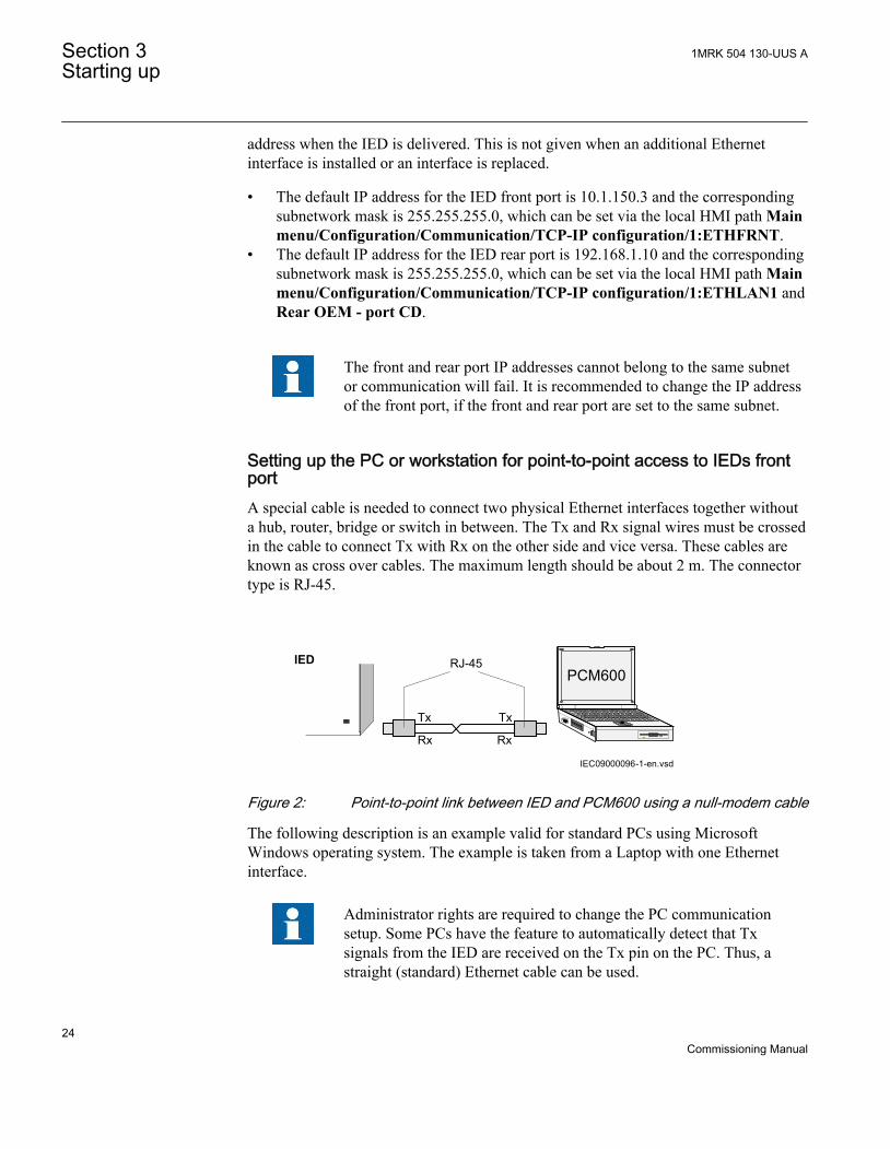
Setting up the PC or workstation for point-to-point access to IEDs frontportA special cable is needed to connect two physical Ethernet interfaces together withouta hub, router, bridge or switch in between. The Tx and Rx signal wires must be crossedin the cable to connect Tx with Rx on the other side and vice versa. These cables areknown as cross over cables. The maximum length should be about 2 m. The connectortype is RJ-45.
IEC09000096-1-en.vsd
PCM600
Tx Tx
Rx Rx
RJ-45IED
IEC09000096 V1 EN
Figure 2: Point-to-point link between IED and PCM600 using a null-modem cable
The following description is an example valid for standard PCs using MicrosoftWindows operating system. The example is taken from a Laptop with one Ethernetinterface.
Administrator rights are required to change the PC communicationsetup. Some PCs have the feature to automatically detect that Txsignals from the IED are received on the Tx pin on the PC. Thus, astraight (standard) Ethernet cable can be used.
Section 3 1MRK 504 130-UUS AStarting up
24Commissioning Manual

When a PC is connected to the IED and the setting DHCPServer is set to Enabled viathe local HMI path Main menu/Configuration/Communication/TCP-IPconfiguration/1:ETHFRNT/DHCPServer, the IEDs DHCP server for the front portassigns an IP address for the PC. The PC must be configured to obtain its IP addressautomatically as described in the following procedure.
1. Select Network Connections in the PC.
IEC09000355-1-en.vsdIEC09000355 V1 EN
Figure 3: Select: Network connections
2. Select Properties in the status window.
1MRK 504 130-UUS A Section 3Starting up
25Commissioning Manual

IEC09000356-1-en.vsdIEC09000356 V1 EN
Figure 4: Right-click Local Area Connection and select Properties
3. Select the TCP/IP protocol from the list of configured components using thisconnection and click Properties.
IEC09000357-1-en.vsdIEC09000357 V1 EN
Figure 5: Select the TCP/IP protocol and open Properties
4. Select Obtain an IP address automatically if the parameter DHCPServer is setto Enabled in the IED.
Section 3 1MRK 504 130-UUS AStarting up
26Commissioning Manual

IEC09000358-1-en.vsdIEC09000358 V1 EN
Figure 6: Select: Obtain an IP address automatically
5. Select Use the following IP address and define IP address and Subnet mask if thefront port is used and if the IP address is not set to be obtained automatically bythe IED, see Figure 7. The IP address must be different from the IP address chosenfor the IED.
1MRK 504 130-UUS A Section 3Starting up
27Commissioning Manual

IEC09000658-1-en.vsdIEC09000658 V1 EN
Figure 7: Select: Use the following IP address
6. Close all open windows and start PCM600.
Setting up the PC to access the IED via a networkThis task depends on the used LAN/WAN network.
The PC and IED must belong to the same subnetwork for this set-up towork.
3.6 Writing an application configuration to the IED
Ensure that the IED includes the correct application configurationaccording to project specifications.
The application configuration is created using PCM600 and then written to the IED.Establish a connection between PCM600 and the IED when an applicationconfiguration must be written to the IED.
Section 3 1MRK 504 130-UUS AStarting up
28Commissioning Manual

After writing an application configuration to the IED, the IED makes an applicationrestart or a complete IED restart, when necessary.
The IED does not restart after reconfiguring IEC61850 (regardless ofwhether the protocol is enabled or disabled).
Be sure to set the correct technical key in both the IED and PCM600 toprevent writing an application configuration to a wrong IED.
See the engineering manual for information on how to create or modifyan application configuration and how to write to the IED.
3.7 Checking CT circuits
Check that the wiring is in strict accordance with the suppliedconnection diagram.
• Primary injection test to verify the current ratio of the CT, the correct wiring up tothe protection IED and correct phase sequence connection (that is A, B, C.)
• CT secondary loop resistance measurement to confirm that the current transformersecondary loop DC resistance is within specification and that there are no highresistance joints in the CT winding or wiring.
• Grounding check of the individual CT secondary circuits to verify that each three-phase set of main CTs is properly connected to the station ground and only at oneelectrical point.
• Insulation resistance check.
CT and VT connectors are pre-coded, and the CT and VT connectormarkings are different. For more information, see the installation manual.
Both the primary and the secondary sides must be disconnected fromthe line and the IED when plotting the excitation characteristics.
1MRK 504 130-UUS A Section 3Starting up
29Commissioning Manual

3.8 Checking VT circuits
Check that the wiring is in strict accordance with the supplied connection diagram.
Correct possible errors before continuing to test the circuitry.
Test the circuitry.
• Polarity check• VT circuit voltage measurement (primary injection test)• Grounding check• Phase relationship• Insulation resistance check
The polarity check verifies the integrity of circuits and the phase relationships. Thecheck must be performed as close to the IED as possible.
The primary injection test verifies the VT ratio and the wiring all the way from theprimary system to the IED. Injection must be performed for each phase-to-neutralcircuit and each phase-to-phase pair. In each case, voltages in all phases and neutral aremeasured.
3.9 Checking the RTXP test switch
The RTXP test switch is designed to provide the means of safe testing of the IED. Thisis achieved by the electromechanical design of the test switch and test plug handle.When the test plug handle is inserted, it first blocks the trip and alarm circuits then itshort circuits the CT secondary circuit and opens the VT secondary circuits making theIED available for secondary injection.
When pulled out, the test handle is mechanically stopped in half withdrawn position. Inthis position, the current and voltage enter the protection, but the alarm and trip circuitsare still isolated. Before removing the test handle, check that no trip or alarms arepresent in the IED.
Not until the test handle is completely removed, the trip and alarm circuits are restoredfor operation.
Section 3 1MRK 504 130-UUS AStarting up
30Commissioning Manual

By pulling in all cables, verify that the contact sockets have beencrimped correctly and that they are fully inserted. Never do this withcurrent circuits in service.
Current circuit
1. Verify that the contacts are of current circuit type.2. Verify that the short circuit jumpers are located in the correct slots.
Voltage circuit
1. Verify that the contacts are of voltage circuit type.2. Check that no short circuit jumpers are located in the slots dedicated for voltage.
Trip and alarm circuits
1. Check that the correct types of contacts are used.
3.10 Checking binary input and output circuits
3.10.1 Binary input circuitsPreferably, disconnect the binary input connector from the binary input cards. Checkall connected signals so that both input level and polarity are in accordance with theIED specifications.
3.10.2 Binary output circuitsPreferably, disconnect the binary output connector from the binary output cards. Checkall connected signals so that both load and polarity are in accordance with IEDspecifications.
3.11 Checking optical connections
Check that the Tx and Rx optical connections are correct.
An IED equipped with optical connections requires a minimum depthof 180 mm (7.2 inches) for plastic fiber cables and 275 mm (10.9
1MRK 504 130-UUS A Section 3Starting up
31Commissioning Manual

inches) for glass fiber cables. Check the allowed minimum bendingradius from the optical cable manufacturer.
Section 3 1MRK 504 130-UUS AStarting up
32Commissioning Manual

Section 4 Establishing connection and verifying theIEC 61850 station communication
4.1 Setting the station communication
To enable IEC 61850 station communication:
• The IEC 61850-8-1 station communication functionality must be on in the localHMI. Navigate to Main menu/Configuration/Communication/Stationcommunication/1:IEC61850-8-1 and set the Operation parameter to Enabled.
• To enable GOOSE communication the Operation parameter for the correspondingGOOSE function blocks (GOOSEBINRCV and GOOSEINTLKRCV) must be setto Enabled in the application configuration.
• To enable GOOSE communication via the front port the parameter GOOSE inMain menu/Configuration/Communication/Station communication/IEC61850-8-1 must be set to Front. To enable GOOSE communication via rearport the parameter GOOSE must be set to LAN1.
4.2 Verifying the communication
Connect your PC to the substation network and ping the connected IED and theSubstation Master PC, to verify that the communication is working (up to the transportlayer).
The best way to verify the communication up to the application layer is to use protocolanalyzer ITT600 connected to the substation bus, and monitor the communication.
1MRK 504 130-UUS A Section 4Establishing connection and verifying the IEC 61850 station communication
33Commissioning Manual

34

Section 5 Testing IED operation
5.1 Preparing the IED to verify settings
If a test switch is included, start preparation by making the necessary connections tothe test switch. This means connecting the test equipment according to a specific anddesignated IED terminal diagram.
Put the IED into the test mode to facilitate the test of individual functions and preventunwanted operation caused by other functions. The test switch should then beconnected to the IED.
Verify that analog input signals from the analog input module are measured andrecorded correctly by injecting currents and voltages required by the specific IED.
To make testing even more effective, use PCM600. PCM600 includes the Signalmonitoring tool, which is useful in reading the individual currents and voltages, theiramplitudes and phase angles. In addition, PCM600 contains the Disturbance handlingtool. The content of reports generated by the Disturbance handling tool can beconfigured which makes the work more efficient. For example, the tool may beconfigured to only show time tagged events and to exclude analog information and so on.
Check the disturbance report settings to ensure that the indications are correct.
For test functions and test and signal parameter names, see the technical manual. Thecorrect initiation of the disturbance recorder is made on pickup and/or release or tripfrom a function. Also check that the wanted recordings of analogue (real andcalculated) and binary signals are achieved.
The IEDs in the 650 series can have between 1 and 4 individual parameter settinggroups prepared with full sets of different parameters for all functions. The purpose ofthese groups is to be able to handle different power system load conditions to optimizethe parameters settings of the different functions for these different power systemsconditions (for example summer/winter and day/night).
Parameters can be entered into different setting groups. Make sure totest functions for the same parameter setting group. If needed, repeatthe tests for all different setting groups used. The difference betweentesting the first parameter setting group and the remaining is that thereis no need for testing the connections.
1MRK 504 130-UUS A Section 5Testing IED operation
35Commissioning Manual

During testing, observe that the right testing method, that corresponds to the actualparameters set in the activated parameter setting group, is used.
Set and configure the function(s) before testing. Most functions are highly flexible andpermit a choice of functional and tripping modes. The various modes are checked atthe factory as part of the design verification. In certain cases, only modes with a highprobability of coming into operation need to be checked when commissioned to verifythe configuration and settings.
Requirements for testing the function.
• Calculated settings• Valid configuration diagram for the IED• Valid terminal diagram for the IED• Technical manual• Three-phase test equipment
Content of the technical manual.
• Application and functionality summaries• Function blocks• Logic diagrams• Input and output signals• A list of setting parameters• Technical data for the function
The test equipment should be able to provide a three-phase supply of currents and three-phase voltage. The magnitude and angle of currents (and voltages) should be possibleto vary. Check that the IED is prepared for test before starting the test session.Consider the logic diagram of the function when performing the test.
The response from a test can be viewed in different ways.
• Binary output signals• Service values in the local HMI (logical signal or phasors)• A PC with PCM600 (configuration software) in debug mode
Do not switch off the auxiliary power supply to the IED beforechanges, for example, setting parameter or local/remote control statechanges are saved.
A mechanism for limiting the number of writings per time period is included in theIED to prevent the flash memory to be worn out due to too many writings. As a
Section 5 1MRK 504 130-UUS ATesting IED operation
36Commissioning Manual

consequence it may take up to an hour to save changes. If the auxiliary power isinterrupted before a change is saved, that change is lost.
5.2 Activating test mode
Put the IED into the test mode before testing. The test mode blocks all protectionfunctions and some of the control functions in the IED, and the individual functions tobe tested can be unblocked to prevent unwanted operation caused by other functions. Inthis way, it is possible to test slower back-up measuring functions without theinterference from faster measuring functions. Test mode is indicated when the yellowPickupLED flashes.
Procedure
1. Select Main menu/Tests/IED test mode/1:TESTMODE2. Set parameter TestMode to Enabled.3. Save the changes.
As a consequence, the yellow pickupLED starts flashing as a reminder andremains flashing until the test mode is switched off.
5.3 Preparing the connection to the test equipment
The IED can be equipped with a test switch of type RTXP8, RTXP18 or RTXP24 orFT. The test switch and its associated test plug handles are a part of the COMBITESTor FT system of ABB, which provides secure and convenient testing of the IED.
When using the COMBITEST, preparations for testing are automatically carried out inthe proper sequence, that is, for example, blocking of tripping circuits, short circuitingof CT’s, opening of voltage circuits, making IED terminals available for secondaryinjection. Terminals 1 and 8, 1 and 18 as well as 1 and 12 of the test switches RTXP8,RTXP18 and RTXP24 respectively are not disconnected as they supply DC power tothe protection IED. When FT switch is used for testing, care shall be exercised to openthe tripping circuit, ahead of manipulating the CT fingers.
The RTXH test-plug handle leads may be connected to any type of test equipment orinstrument. When a number of protection IEDs of the same type are tested, the test-plug handle only needs to be moved from the test switch of one protection IED to thetest switch of the other, without altering the previous connections.
Use COMBITEST test system to prevent unwanted tripping when the handle iswithdrawn, since latches on the handle secure it in the half withdrawn position. In this
1MRK 504 130-UUS A Section 5Testing IED operation
37Commissioning Manual

position, all voltages and currents are restored and any re-energizing transients aregiven a chance to decay before the trip circuits are restored. When the latches arereleased, the handle can be completely withdrawn from the test switch, restoring thetrip circuits to the protection IED.
If a test switch is not used, perform measurement according to the provided circuitdiagrams.
Never disconnect the secondary connection of a current transformercircuit without first short-circuiting the transformer's secondarywinding. Operating a current transformer with the secondary windingopen will cause a massive potential build up that may damage thetransformer and cause personal injury.
5.4 Connecting the test equipment to the IED
Connect the test equipment according to the IED specific connection diagram and theneeded input and output signals for the function under test. An example of aconnection is shown in figure 8.
Connect the current and voltage terminals. Pay attention to the current polarity. Makesure that the connection of input and output current terminals and the connection of theresidual current conductor is correct. Check that the input and output logical signals inthe logic diagram for the function under test are connected to the corresponding binaryinputs and outputs of the IED under test.
To ensure correct results, make sure that the IED as well as the testequipment are properly grounded before testing.
Section 5 1MRK 504 130-UUS ATesting IED operation
38Commissioning Manual

IAIBICIN
VAVBVCN
IAIBIC
VA
IN
TRIPTe
st e
quip
men
t
IED
ANSI09000643-1-en.vsd
VBVCN
VN
IEC 61850
ANSI09000643 V1 EN
Figure 8: Connection example of the test equipment to the IED when testequipment is connected to the transformer input module
5.5 Releasing the function to be tested
Release or unblock the function to be tested. This is done to ensure that only thefunction or the chain of functions to be tested are in operation and that other functionsare prevented from operating. Release the tested function(s) by setting thecorresponding Blocked parameter under Function test modes to No in the local HMI.
When testing a function in this blocking feature, remember that not only the actualfunction must be activated, but the whole sequence of interconnected functions (frommeasuring inputs to binary output contacts), including logic must be activated. Beforestarting a new test mode session, scroll through every function to ensure that only thefunction to be tested (and the interconnected ones) have the parameters Blocked andeventually EvDisable set to No and Yes respectively. Remember that a function is alsoblocked if the BLOCK input signal on the corresponding function block is active,which depends on the configuration. Ensure that the logical status of the BLOCK inputsignal is equal to 0 for the function to be tested. Event function blocks can also beindividually blocked to ensure that no events are reported to a remote station during thetest. This is done by setting the parameter EvDisable to Yes.
1MRK 504 130-UUS A Section 5Testing IED operation
39Commissioning Manual

Any function is blocked if the corresponding setting in the local HMIunder Main menu/Tests/Function test modes menu remains Enabled,that is, the parameter Blocked is set to Yes and the parameter TestModeunder Main menu/Tests/IED test mode remains active. All functionsthat were blocked or released in a previous test mode session, that is,the parameter Test mode is set to Enabled, are reset when a new testmode session is started.
Procedure
1. Click the Function test modes menu.The Function test modes menu is located in the local HMI under Main menu/Tests/Function test modes.
2. Browse to the function instance that needs to be released.3. Set parameter Blocked for the selected function to No.
5.6 Verifying analog primary and secondary measurement
Verify that the connections are correct and that measuring and scaling is donecorrectly. This is done by injecting current and voltage to the IED.
Apply input signals as needed according to the actual hardware and theapplication configuration.
1. Inject a symmetrical three-phase voltage and current at rated value.2. Compare the injected value with the measured values.
The voltage and current phasor menu in the local HMI is located under Mainmenu/Measurements/Analog primary values and Main menu/Measurements/Analog secondary values.
3. Compare the frequency reading with the set frequency and the direction of thepower.The frequency and active power are located under Main menu/Tests/Functionstatus/Monitoring/CVMMXN/1:CVMMXN/Outputs. Then navigate to thebottom of the list to find the frequency.
Check both analog primary and secondary values, because thenthe CT and VT ratios entered into the IED are also checked.
Section 5 1MRK 504 130-UUS ATesting IED operation
40Commissioning Manual

These checks shall be repeated for Analog primary values.4. Inject an unsymmetrical three-phase voltage and current, to verify that phases are
correctly connected.
If some setting deviates, check the analog input settings under
Main menu/Configuration/Analog modules
Measured values such as current and voltages as well as active, reactive and apparentpower, power factor phase angles as well as positive and negative and zero sequencecurrents and voltages are available in the local HMI under Main menu/Tests/Functionstatus/Monitoring.
Navigate to the measurement function that contains the quantity to be checked.
Table 1: Measurement functions
Function Quantity DescriptionCMMXU IA to IC amplitude, range and angle
CMSQI 3I0; I1 and I2 amplitude, range and angle
CVMMXN S; P; Q; PF; Ilag; Ilead; U; I and f amplitude, range and angle
VMMXU VA_C to VC_A i.e. phase-to-phase
amplitude, range and angle
VMSQI 3U0; U1 and U2 amplitude, range and angle
VNMMXU VA to VC i.e. phase-to-neutral amplitude, range and angle
Also the Signal Monitoring tool in PCM600 can be used to read the measured values.In many cases it is more convenient to use PCM600 since, among many things, reportson measured values can be exported from the Signal Monitoring tool to other tools (forexample, MS Excel) for further analysis.
5.7 Testing protection functionality
Each protection function must be tested individually by secondary injection.
• Verify operating levels (trip) and timers.• Verify alarm and blocking signals.• Use the disturbance handling tool in PCM600 to evaluate that the protection
function has received the correct data and responded correctly (signaling and timing).• Use the event viewer tool in PCM600 to check that only expected events have
occurred.
1MRK 504 130-UUS A Section 5Testing IED operation
41Commissioning Manual

42

Section 6 Testing functionality
6.1 Testing disturbance report
6.1.1 IntroductionThe following sub-functions are included in the disturbance report function:
• Disturbance recorder• Event list• Event recorder• Trip value recorder• Indications
If the disturbance report is enabled, then its sub-functions are also set up and so it isnot possible to only disable these sub-functions. The disturbance report function isdisabled (parameter Operation = Disabled) in PCM600 or the local HMI under Mainmenu/Settings/IED Settings/Monitoring/Disturbance report/1:DRPRDRE.
6.1.2 Disturbance report settingsWhen the IED is in test mode, the disturbance report can be made active or inactive. Ifthe disturbance recorder is turned on during test mode, recordings will be made. Whentest mode is switched off all recordings made during the test session are cleared.
Setting OpModeTest for the control of the disturbance recorder during test mode arelocated on the local HMI under Main menu/Settings/IED Settings/Monitoring/Disturbance report/1:DRPRDRE.
6.2 Identifying the function to test in the technicalreference manual
Use the technical manual to identify function blocks, logic diagrams, input and outputsignals, setting parameters and technical data.
1MRK 504 130-UUS A Section 6Testing functionality
43Commissioning Manual

6.3 Testing differential protection functions
6.3.1 Transformer differential protection T2WPDIF (87T) andT3WPDIF (87T)(87T)Prepare the IED for verification of settings as outlined in 5.1 "Preparing the IED toverify settings".
Values of the logical signals for T2WPDIF (87T) are available on the local HMI underMain menu/Tests/Function status/Differential/T2WPDIF(87T,Id)/1:T2WPDIF.The Signal Monitoring in PCM600 shows the same signals that are available on thelocal HMI.
Values of the logical signals for T3WPDIF (87T) are available on the local HMI underMain menu/Tests/Function status/Differential/T3WPDIF(87T,Id)/1:T3WPDIF.The Signal Monitoring in PCM600 shows the same signals that are available on thelocal HMI.
6.3.1.1 Verifying the settings
1. Go to Main menu/Test/Function test modes/Differential protection and makesure that the restricted earth fault protection, low impedance function REFPDIF(87N) is set to Disabled and that the four step residual overcurrent functionEF4PTOC (51N/67N) under Main menu/Test/Function test modes/Currentprotection is set to Disabled, since they are configured to the same currenttransformer inputs as the transformer differential protection. Make sure that thetransformer differential functions T2WPDIF (87T) or T3WPDIF (87T) areunblocked.
2. Connect the test set for injection of three-phase currents to the current terminalsof the IED, which are connected to the CTs on the HV side of the power transformer.
3. Increase the current in phase A until the protection function operates and note theoperating current.
4. Check that the trip and alarm contacts operate according to the configuration logic.5. Decrease the current slowly from operate value and note the reset value.
Depending on the power transformer vector group (Yd and so on), the single-phase injection current will be different by a factor k from the three-phase pickup,see step 7. This factor k can have one of the following three values: 1.0, or 1.5, or2.0.
6. Check in the same way the function by injecting current in phases B and Crespectively. Phase B and Cpickup shall be the same as for phase A.
7. Inject a symmetrical three-phase current and note the operate value.8. Connect the timer and set the current to twice the operate value.
Section 6 1MRK 504 130-UUS ATesting functionality
44Commissioning Manual

9. Switch on the current and note the operate time.10. Check in the same way the functioning of the measuring circuits connected to the
CTs on the LV side and other current inputs to the transformer differentialprotection.
11. Finally check that trip information is stored in the event menu.12. If available on the test set, a second harmonic current of about 20% (assumes
15% setting on I1/I2 ratio parameter) can be added to the fundamental tone inphase A. Increase the current in phase A above the pickup value measured in step6. Repeat test with current injection in phases B and C respectively.
Note that during this test setting SOTFMode must be set toDisabled.
The balancing of currents flowing into and out of the differential zone is typicallychecked by primary testing when suitable supply facilities exist on site.Fifth harmonic blocking can be tested in a similar way. Note, the blocking levelfor the fifth harmonic is 10% higher than the I5/I1 Ratio setting.
6.3.1.2 Completing the test
Continue to test another function or end the testing by setting the parameter TestModeto Disabled under Main menu/Tests/IED test mode/1:TESTMODE. If anotherfunction is tested, then set the parameter Blocked to No under Main menu/Tests/Function test modes/Differential/T2WPDIF(87T,Id)/1:T2WPDIF for the function,or for each individual function in a chain, to be tested next. Remember to set theparameter Blocked to Yes, for each individual function that has been tested.
Continue to test another function or end the testing by setting the parameter TestModeto Disabled under Main menu/Tests/IED test mode/1:TESTMODE. If anotherfunction is tested, then set the parameter Blocked to No under Main menu/Tests/Function test modes/Differential/T3WPDIF(87T,Id)/1:T3WPDIF for the function,or for each individual function in a chain, to be tested next. Remember to set theparameter Blocked to Yes, for each individual function that has been tested.
6.3.2 Restricted earth fault protection, low impedance REFPDIF(87N)Prepare the IED for verification of settings as outlined in 5.1 "Preparing the IED toverify settings".
Values of the logical signals for REFPDIF (87) are available on the local HMI underMain menu/Tests/Function status/Differential/REFPDIF(87,INd)/X:REFPDIF.
1MRK 504 130-UUS A Section 6Testing functionality
45Commissioning Manual

The Signal Monitoring in PCM600 shows the same signals that are available on thelocal HMI.
6.3.2.1 Verifying the settings
1. Connect the test set for single-phase current injection to the protection terminalsconnected to the CT in the power transformer neutral-to-ground circuit.
2. Increase the injection current and note the operating value of the protectionfunction.
3. Check that all trip and pickup contacts operate according to the configuration logic.4. Decrease the current slowly from operate value and note the reset value.5. Connect the timer and set the current to ten times the value of the trip time in the
IDmin settings.6. Switch on the current and note the operate time.7. Connect the test set to terminal A and neutral of the three-phase current input
configured to REFPDIF (87N). Also inject a current higher than half the Idminsetting in the neutral-to-ground circuit with the same phase angle and withpolarity corresponding to an internal fault.
8. Increase the current injected in A, and note the operate value. Decrease thecurrent slowly and note the reset value.
9. Inject current into terminals B and C in the same way as in point 7 above and notethe operate and reset values.
10. Inject a current equal to 10% of rated current into terminal A.11. Inject a current in the neutral-to-ground circuit with the same phase angle and
with polarity corresponding to an external fault.12. Increase the current to five times the operating value and check that the protection
does not operate.13. Finally check that trip information is stored in the event and disturbance recorder.
6.3.2.2 Completing the test
Continue to test another function or end the testing by setting the parameter TestModeto Disabled under Main menu/Tests/IED test mode/1:TESTMODE. If anotherfunction is tested, then set the parameter Blocked to No under Main menu/Tests/Function test modes/Differential/REFPDIF(87,INd)/X:REFPDIF for the function,or for each individual function in a chain, to be tested next. Remember to set theparameter Blocked to Yes, for each individual function that has been tested.
6.3.3 High impedance differential protection HZPDIF (87)Prepare the IED for verification of settings as outlined in 5.1 "Preparing the IED toverify settings".
Section 6 1MRK 504 130-UUS ATesting functionality
46Commissioning Manual

Values of the logical signals for HZPDIF (87) are available on the local HMI underMain menu/Tests/Function status/Differential/HZPDIF(87,IdN)/X:HZPDIF. TheSignal Monitoring in PCM600 shows the same signals that are available on the local HMI.
6.3.3.1 Verifying the settings
1. Connect single-phase or three-phase test set to inject the operating voltage. Theinjection shall be on the primary side of the stabilizing resistor.
The operating voltage is adjusted on the stabilizing resistor andthe setting of the resistor value must be done in the function. Thisis essential for the measurement of the expected value. Normally aslightly higher operating value is no problem as the sensitivity isnot influenced much.
2. Increase the voltage and make note of the operate value Pickup. This is done bymanual testing and without trip of the test set.
3. Connect the trip contact to the test set to stop the test set for measurement of triptimes below.
4. Reduce the voltage slowly and make note of the reset value. The reset value mustbe high for this function.
5. Check the operating time by injecting a voltage corresponding to 1.2 · Pickuplevel. Make note of the measured trip time.
6. If required, verify the trip time at another voltage. Normally 2 · Pickup is selected.7. If used, measure the alarm level operating value. Increase the voltage and make
note of the operate value AlarmPickup. This is done with manual test and withouttrip of the test set.
8. Measure the operating time on the alarm output by connecting the stop of the testset to an output from tAlarm. Inject a voltage 1.2 · AlarmPickup and measure thealarm time.
9. Check that trip and alarm outputs operate according to the configuration logic.10. Finally check that pickup and alarm information is stored in the event menu and
if a serial connection to the SA is available verify that the correct and only therequired signals are presented on the local HMI and on the SCADA system.
Information on how to use the event menu is found in the operator'smanual.
1MRK 504 130-UUS A Section 6Testing functionality
47Commissioning Manual

6.3.3.2 Completing the test
Continue to test another function or end the testing by setting the parameter TestModeto Disabled under Main menu/Tests/IED test mode/1:TESTMODE. If anotherfunction is tested, then set the parameter Blocked to No under Main menu/Tests/Function test modes/Differential/HZPDIF(87,IdN)/X:HZPDIF for the function, orfor each individual function in a chain, to be tested next. Remember to set theparameter Blocked to Yes, for each individual function that has been tested.
6.4 Testing current protection functions
6.4.1 Instantaneous phase overcurrent protection 3-phase outputPHPIOC (50)Prepare the IED for verification of settings as outlined in 5.1 "Preparing the IED toverify settings".
Values of the logical signals for PHPIOC (50) are available on the local HMI underMain menu/Tests/Function status/Current/PHPIOC(50,I>>)/1:PHPIOC. TheSignal Monitoring in PCM600 shows the same signals that are available on the local HMI.
To verify the settings the following fault type should be tested:
• Phase-to-ground fault
Ensure that the maximum continuous current, supplied from the current source used forthe test of the IED, does not exceed four times the rated current value of the IED.
6.4.1.1 Measuring the operate limit of set values
1. Inject a phase current into the IED with an initial value below that of the setting.2. Increase the injected current until the TRIP signal appears.3. Switch the fault current off.
Observe: Do not exceed the maximum permitted overloading ofthe current circuits in the IED.
4. Compare the measured operating current with the set value.
Section 6 1MRK 504 130-UUS ATesting functionality
48Commissioning Manual

6.4.1.2 Completing the test
Continue to test another function or end the testing by setting the parameter TestModeto Disabled under Main menu/Tests/IED test mode/1:TESTMODE. If anotherfunction is tested, then set the parameter Blocked to No under Main menu/Tests/Function test modes/Current/PHPIOC(50,I>>)/1:PHPIOC for the function, or foreach individual function in a chain, to be tested next. Remember to set the parameterBlocked to Yes, for each individual function that has been tested.
6.4.2 Four step phase overcurrent protection 3-phase outputOC4PTOC (51_67)Prepare the IED for verification of settings as outlined in 5.1 "Preparing the IED toverify settings".
Values of the logical signals for OC4PTOC (51_67) are available on the local HMIunder Main menu/Tests/Function status/Current/OC4PTOC(51_67,4I>)/1:OC4PTOC. The Signal Monitoring in PCM600 shows the same signals that areavailable on the local HMI.
6.4.2.1 Verifying the settings
1. Connect the test set for current injection to the appropriate IED phases.If there is any configuration logic that is used to enable or block any of the fouravailable overcurrent steps, make sure that the step under test is enabled (forexample, end fault protection).Connect the symmetrical three-phase injection current into phases A, B and C.
2. Connect the test set for the appropriate three-phase voltage injection to the IEDphases A, B and C. The protection shall be fed with a symmetrical three-phasevoltage.
3. Set the injected polarizing voltage slightly larger than the set minimum polarizingvoltage (default is 5% of VBase) and set the injection current to lag theappropriate voltage by an angle of 55° if forward directional function is selected.If 1 out of 3 currents for operation is chosen: The voltage angle of phase A is thereference.If reverse directional function is selected, set the injection current to lag thepolarizing voltage by an angle equal to 235° (equal to 55° + 180°).
4. Increase the injected current and note the operate value of the tested step of thefunction.
5. Decrease the current slowly and note the reset value.
1MRK 504 130-UUS A Section 6Testing functionality
49Commissioning Manual

6. If the test has been performed by injection of current in phase A, repeat the test,injecting current into phases B and C with polarizing voltage connected to phasesB, respectively C (1 out of 3 currents for operation).
7. If the test has been performed by injection of current in phases AB, repeat thetest, injecting current into phases BC and CA with the appropriate phase angle ofinjected currents.
8. Block higher set stages when testing lower set stages by following the proceduredescribed below.
9. Connect a trip output contact to a timer.10. Set the injected current to 200% of the operate level of the tested stage, switch on
the current and check the time delay.For inverse time curves, check the operate time at a current equal to 110% of theoperate current for txMin.
11. Check that all trip and pickup contacts operate according to the configuration(signal matrixes)
12. Reverse the direction of the injected current and check that the protection doesnot operate.
13. Repeat the above described tests for the higher set stages.14. Finally check that pickup and trip information is stored in the event menu.
Verification of the non-directional phase overcurrent function isdone as instructed above, without applying any polarizing voltage.
6.4.2.2 Completing the test
Continue to test another function or end the testing by setting the parameter TestModeto Disabled under Main menu/Tests/IED test mode/1:TESTMODE. If anotherfunction is tested, then set the parameter Blocked to No under Main menu/Tests/Function test modes/Current/OC4PTOC(51_67,4I>)/1:OC4PTOC for the function,or for each individual function in a chain, to be tested next. Remember to set theparameter Blocked to Yes, for each individual function that has been tested.
6.4.3 Instantaneous residual overcurrent protection EFPIOC (50N)Prepare the IED for verification of settings as outlined in 5.1 "Preparing the IED toverify settings".
Values of the logical signals for EFPIOC (50N) are available on the local HMI underMain menu/Tests/Function status/Current/EFPIOC(50N,IN>>)/1:EFPIOC. TheSignal Monitoring in PCM600 shows the same signals that are available on the local HMI.
To verify the settings the following fault type should be tested:
Section 6 1MRK 504 130-UUS ATesting functionality
50Commissioning Manual

• Phase-to-ground fault
Ensure that the maximum continuous current, supplied from the current source used forthe test of the IED, does not exceed four times the rated current value of the IED.
6.4.3.1 Measuring the operate limit of set values
1. Inject a phase current into the IED with an initial value below that of the setting.2. Increase the injected current in the Ln or in the neutral (summated current input)
phase until the TRIP signal appears.3. Disable the fault current
Observe to not exceed the maximum permitted overloading of the current circuitsin the IED
4. Compare the measured operating current with the set value.
6.4.3.2 Completing the test
Continue to test another function or end the testing by setting the parameter TestModeto Disabled under Main menu/Tests/IED test mode/1:TESTMODE. If anotherfunction is tested, then set the parameter Blocked to No under Main menu/Tests/Function test modes/Current/EFPIOC(50N,IN>>)/1:EFPIOC for the function, orfor each individual function in a chain, to be tested next. Remember to set theparameter Blocked to Yes, for each individual function that has been tested.
6.4.4 Four step residual overcurrent protection, zero or negativesequence direction EF4PTOC (51N/67N)
Prepare the IED for verification of settings as outlined in 5.1 "Preparing the IED toverify settings".
Values of the logical signals for EF4PTOC (51N67N) are available on the local HMIunder Main menu/Tests/Function status/Current/EF4PTOC(51N67N,4IN>)/X:EF4PTOC. The Signal Monitoring in PCM600 shows the same signals that areavailable on the local HMI.
6.4.4.1 Four step directional residual overcurrent protection
1. Connect the test set for single current injection to the appropriate IED terminals.
1MRK 504 130-UUS A Section 6Testing functionality
51Commissioning Manual

Connect the injection current and voltage to terminals A and neutral.2. Set the injected polarizing voltage slightly larger than the set minimum polarizing
voltage (default 1% of Vn) and set the injection current to lag the voltage by anangle equal to the set reference characteristic angle (AngleRCA), if the forwarddirectional function is selected.If reverse directional function is selected, set the injection current to lag thepolarizing voltage by an angle equal to RCA+ 180°.
3. Increase the injected current and note the value at which the studied step of thefunction operates.
4. Decrease the current slowly and note the reset value.5. If the test has been performed by injection of current in phase A, repeat the test,
injecting current into terminals B and C with a polarizing voltage connected toterminals B, respectively C.
6. Block lower set steps when testing higher set steps according to the instructionsthat follow.
7. Connect a trip output contact to a timer.8. Set the injected current to 200% of the operate level of the tested step, switch on
the current and check the time delay.For inverse time curves, check the operate time at a current equal to 110% of theoperate current for txMin.
9. Check that all trip and trip contacts operate according to the configuration (signalmatrixes)
10. Reverse the direction of the injected current and check that the step does not operate.11. Check that the protection does not operate when the polarizing voltage is zero.12. Repeat the above described tests for the higher set steps.13. Finally, check that pickup and trip information is stored in the event menu.
6.4.4.2 Four step non-directional residual overcurrent protection
1. Do as described in "Four step directional residual overcurrent protection", butwithout applying any polarizing voltage.
6.4.4.3 Completing the test
Continue to test another function or end the testing by setting the parameter TestModeto Disabled under Main menu/Tests/IED test mode/1:TESTMODE. If anotherfunction is tested, then set the parameter Blocked to No under Main menu/Tests/Function test modes/Current/EF4PTOC(51N67N,4IN>)/X:EF4PTOC for thefunction, or for each individual function in a chain, to be tested next. Remember to setthe parameter Blocked to Yes, for each individual function that has been tested.
Section 6 1MRK 504 130-UUS ATesting functionality
52Commissioning Manual

6.4.5 Thermal overload protection, two time constants TRPTTR (49)Prepare the IED for verification of settings as outlined in 5.1 "Preparing the IED toverify settings".
Values of the logical signals for TRPTTR (49) are available on the local HMI underMain menu/Tests/Function status/Current/TRPTTR(49,T>)/X:TRPTTR. TheSignal Monitoring in PCM600 shows the same signals that are available on the local HMI.
6.4.5.1 Checking operate and reset values
1. Connect symmetrical three-phase currents to the appropriate current terminals ofthe IED.
2. Set the Time constant 1 (Tau1) and Time Constant 2 (Tau2) temporarily to 1 minute.3. Set the three-phase injection currents slightly lower than the set operate value of
stage IBase1, increase the current in phase A until stage IBase1 operates and notethe operate value.
Observe the maximum permitted overloading of the currentcircuits in the IED.
4. Decrease the current slowly and note the reset value.
Check, in the same way, the operate and reset values of IBase1 for phases B andC.
5. Activate the cooling input signal, thus switching to base current IBase2.6. Check the operate and reset values (for all three phases) for IBase2 in the same
way as described above for stage IBase1.7. Deactivate the input signal for stage IBase2.8. Set the time constant for IBase1 in accordance with the setting plan.9. Set the injection current for phase A to 1.50 · IBase1.10. Connect a trip output contact to the timer and monitor the output of contacts
ALARM1 and ALARM2 to digital inputs in test equipment.Read the heat content in the thermal protection from the local HMI and wait untilthe content is zero.
11. Switch on the injection current and check that ALARM1 and ALARM2 contactsoperate at the set percentage level and that the operate time for tripping is inaccordance with the set Time Constant 1 (Tau1).With setting Itr = 101%IBase1 and injection current 1.50 · IBase1, the trip timefrom zero content in the memory shall be 0.60 · Time Constant 1 (Tau1).
12. Check that all trip and alarm contacts operate according to the configuration logic.
1MRK 504 130-UUS A Section 6Testing functionality
53Commissioning Manual

13. Switch off the injection current and check from the service menu readings ofthermal status and LOCKOUT that the lockout resets at the set percentage of heatcontent.
14. Activate the cooling input signal to switch over to base current IBase2.Wait 5 minutes to empty the thermal memory and set Time Constant 2 (Tau2) inaccordance with the setting plan.
15. Test with injection current 1.50 · IBase2 the thermal alarm level, the operate timefor tripping and the lockout reset in the same way as described for stage IBase1.
16. Finally check that pickup and trip information is stored in the event menu.
6.4.5.2 Completing the test
Continue to test another function or end the testing by setting the parameter TestModeto Disabled under Main menu/Tests/IED test mode/1:TESTMODE. If anotherfunction is tested, then set the parameter Blocked to No under Main menu/Tests/Function test modes/Current/TRPTTR(49,T>)/X:TRPTTR for the function, or foreach individual function in a chain, to be tested next. Remember to set the parameterBlocked to Yes, for each individual function that has been tested.
6.4.6 Breaker failure protection, phase segregated activation andoutput CCRBRF (50BF)Prepare the IED for verification of settings as outlined in 5.1 "Preparing the IED toverify settings".
Values of the logical signals for CCRBRF (50BF) are available on the local HMI underMain menu/Tests/Function status/Current/CCRBRF(50BF)/1:CCRBRF. TheSignal Monitoring in PCM600 shows the same signals that are available on the local HMI.
The Breaker failure protection, 3-phase activation and output function CCRBRF(50BF) should normally be tested in conjunction with some other function thatprovides an initiate signal. An external INITIATE signal can also be used.
To verify the settings in the most common back-up trip mode 1 out of 3, it is sufficientto test phase-to-ground faults.
At mode 2 out of 4 the phase current setting, Pickup_PH can be checked by single-phase injection where the return current is connected to the summated current input.The value of residual (ground fault) current IN set lower than Pickup_PH is easiestchecked in back-up trip mode 1 out of 4.
Section 6 1MRK 504 130-UUS ATesting functionality
54Commissioning Manual

6.4.6.1 Checking the phase current operate value, Pickup_PH
Check the current level IP> where setting FunctionMode=Current and settingBuTripMode=1 out of 3 or 2 out of 4 as set under Main menu/Settings/IED Settings/Current/CCRBRF(50BF)/1:CCRBRF.
1. Apply the fault condition, including INITIATION of CCRBRF (50BF), with acurrent below set Pickup_PH.
2. Repeat the fault condition and increase the current in steps until a trip occurs.3. Compare the result with the set Pickup_PH.4. Disconnect AC and INITIATE input signals.
Note! If NoIPickupcheck or Retrip off is set, only back-up trip canbe used to check set Pickup_PH.
6.4.6.2 Checking the residual (ground fault) current operate value Pickup_N setbelow Pickup_PH
Check the low set Pickup_N current where setting FunctionMode = Current and settingBuTripMode = 1 out of 4 as set under Main menu/Settings/IED Settings/Current/CCRBRF(50BF)/1:CCRBRF.
1. Apply the fault condition, including INITIATION of CCRBRF (50BF), with acurrent just below set IN>Pickup_N.
2. Repeat the fault condition and increase the current in steps until trip appears.3. Compare the result with the set Pickup_N.4. Disconnect AC and INITIATION input signals.
6.4.6.3 Checking the re-trip and back-up times
The check of the set times can be made in connection with the check of operate valuesabove.
Choose the applicable function and trip mode, such as FunctionMode = Current andsetting RetripMode = No CBPos. Check as set under Main menu/Settings/IEDSettings/Current/CCRBRF(50BF)/1:CCRBRF.
1. Apply the fault condition, including initiation of CCRBRF (50BF), well abovethe set current value. Measure time from INITIATION of CCRBRF (50BF).
2. Check the re-trip t1 and back-up trip times t2.3. Disconnect AC and INITIATE input signals.
1MRK 504 130-UUS A Section 6Testing functionality
55Commissioning Manual

6.4.6.4 Verifying the re-trip mode
Choose the mode below, which corresponds to the actual case.
In the cases below it is assumed that FunctionMode = Current as set under Main menu/Settings/IED Settings/Current/CCRBRF(50BF)/1:CCRBRF.
Checking the case without re-trip, RetripMode = Retrip Off
1. Set RetripMode = Retrip Off.2. Apply the fault condition, including initiation of CCRBRF (50BF), well above
the set current value.3. Verify that no re-trip, but back-up trip is achieved after set time.4. Disconnect AC and INITIATE input signals.
Checking the re-trip with current check, RetripMode = CB Pos Check
1. Set RetripMode = CB Pos Check.2. Apply the fault condition, including initiation of CCRBRF (50BF), well above
the set current value.3. Verify that re-trip is achieved after set time t1 and back-up trip after time t24. Apply the fault condition, including initiation of CCRBRF (50BF), with current
below set current value.5. Verify that no re-trip, and no back-up trip is obtained.6. Disconnect AC and INITIATE input signals.
Checking re-trip without current check, RetripMode = No CBPos Check
1. Set RetripMode = No CBPos Check.2. Apply the fault condition, including initiation of CCRBRF (50BF), without any
current.3. Verify that re-trip is achieved after set time t1, and back-up trip after time t2.4. Apply the fault condition, including initiation of CCRBRF (50BF), with current
below set current value.5. Verify that re-trip is achieved after set time t1, but no back-up trip is obtained.6. Disconnect AC and INITIATE input signals.
6.4.6.5 Verifying the back-up trip mode
In the cases below it is assumed that FunctionMode = Current is selected.
Checking that back-up tripping is not achieved at normal CB trippingUse the actual tripping modes. The case below applies to re-trip with current check.
Section 6 1MRK 504 130-UUS ATesting functionality
56Commissioning Manual

1. Apply the fault condition, including initiation of CCRBRF (50BF), with phasecurrent well above set value IP.
2. Interrupt the current, with a margin before back-up trip time, t2. It may be madeat issue of re-trip command.
3. Check that re-trip is achieved, if selected, but no back-up trip is obtained.4. Disconnect AC and INITIATE input signals.
The normal mode BuTripMode = 1 out of 3 should have been verified in the testsabove. In applicable cases the modes 1 out of 4 and 2 out of 4 can be checked. Choosethe mode below, which corresponds to the actual case.
Checking the case BuTripMode = 1 out of 4It is assumed that the ground-fault current setting Pickup_N is below phase currentsetting Pickup_PH.
1. Set BuTripMode = 1 out of 4.2. Apply the fault condition, including initiation of CCRBRF (50BF), with one-
phase current below set Pickup_PH but above Pickup_N. The residual ground-fault should then be above set Pickup_N.
3. Verify that back-up trip is achieved after set time. If selected, re-trip should alsoappear.
4. Disconnect AC and INITIATE input signals.
Checking the case BuTripMode = 2 out of 4The ground-fault current setting Pickup_N may be equal to or below phase-currentsetting Pickup_PH.
1. Set BuTripMode = 2 out of 4.2. Apply the fault condition, including initiation of CCRBRF (50BF), with one-
phase current above set Pickup_PH and residual (ground fault) above setPickup_N.
3. Verify that back-up trip is achieved after set time. If selected, re-trip should alsoappear.
4. Apply the fault condition, including initiation of CCRBRF (50BF), with at leastone-phase current below set Pickup_PH and residual (ground fault) above setPickup_N. The current may be arranged by feeding three- (or two-) phasecurrents with equal phase angle (I0-component) below Pickup_PH, but of suchvalue that the residual (ground fault) current (3I0) will be above set valuePickup_N.
5. Verify that back-up trip is not achieved.6. Disconnect AC and INITIATE input signals.
1MRK 504 130-UUS A Section 6Testing functionality
57Commissioning Manual

6.4.6.6 Verifying the case RetripMode = Contact
It is assumed that re-trip without current check is selected, RetripMode = Contact.
1. Set FunctionMode = Contact2. Apply input signal for CB closed to input 52a_A (B or C).3. Apply input signal, for initiation of CCRBRF (50BF).4. Verify that phase selection re-trip and back-up trip are achieved after set times.5. Disconnect the trip signal. Keep the CB closed signal.6. Apply input signal, for initiation of CCRBRF (50BF).7. Arrange disconnection of CB closed signal well before set back-up trip time t2.8. Verify that back-up trip is not achieved.9. Disconnect injected AC and INITIATE input signals.
6.4.6.7 Verifying the function mode Current&Contact
To be made only when FunctionMode = Current&Contact is selected.
Checking the case with fault current above set value Pickup_PHThe operation shall be as in FunctionMode = Current.
1. Set FunctionMode = Current&Contact.2. Leave the inputs for CB close inactivated. These signals should not influence.3. Apply the fault condition, including initiation of CCRBRF (50BF), with current
above the set Pickup_PH value.4. Check that the re-trip, if selected, and back-up trip commands are achieved.5. Disconnect injected AC and INITIATE input signals.
Checking the case with fault current below set value Pickup_BlkContThe case shall simulate a case where the fault current is very low and operation willdepend on CB position signal from CB auxiliary contact. It is suggested that re-tripwithout current check is used, setting RetripMode = No CBPos Check.
1. Set FunctionMode = Current&Contact.2. Apply input signal for CB closed to relevant input or inputs 52a_A (B or C)3. Apply the fault condition with input signal(s) for initiation of CCRBRF (50BF).
The value of current should be below the set value Pickup_BlkCont4. Verify that phase selection re-trip (if selected) and back-up trip are achieved after
set times. Failure to trip is simulated by keeping the signal(s) CB closed activated.5. Disconnect the AC and the INITIATE signal(s). Keep the CB closed signal(s).6. Apply the fault and the initiation again. The value of current should be below the
set value Pickup_BlkCont.
Section 6 1MRK 504 130-UUS ATesting functionality
58Commissioning Manual

7. Arrange disconnection of BC closed signal(s) well before set back-up trip time t2.It simulates a correct CB tripping.
8. Verify that back-up trip is not achieved. Re-trip can appear for example, due toselection “Re-trip without current check”.
9. Disconnect injected AC and INITIATE input signals.
6.4.6.8 Completing the test
Continue to test another function or end the testing by setting the parameter TestModeto Disabled under Main menu/Tests/IED test mode/1:TESTMODE. If anotherfunction is tested, then set the parameter Blocked to No under Main menu/Tests/Function test modes/Current/CCRBRF(50BF)/X:CCRBRF for the function, or foreach individual function in a chain, to be tested next. Remember to set the parameterBlocked to Yes, for each individual function that has been tested.
6.4.7 Pole discrepancy protection CCRPLD (52PD)Prepare the IED for verification of settings as outlined in 5.1 "Preparing the IED toverify settings".
Values of the logical signals for CCRPLD (52PD) are available on the local HMIunder Main menu/Tests/Function status/Current/CCRPLD(52PD)/X:CCRPLD.The Signal Monitoring in PCM600 shows the same signals that are available on thelocal HMI.
6.4.7.1 Verifying the settings
1. When CCRPLD (52PD) is set for external, set setting ContSel to Enable underMain menu/Settings/IED Settings/Current/CCRPLD/1:CCRPLD to activatethe logic that detects pole discordance when external pole discordance signalingis used (input EXTPDIND) in the application configuration.
2. Activate the input EXTPDIND on CCRPLD (52PD) function block, and measurethe operating time of CCRPLD (52PD).
3. Compare the measured time with the set value tTrip.4. Reset the EXTPDIND input.5. When CCRPLD (52PD) is set for unsymmetrical current detection with CB
monitoring, set setting CurrSel under Main menu/Settings/IED Settings/Current/CCRPLD/1:CCRPLD to Enable.Use the TRIP signal from the configured binary output to stop the timer.
6. Repeat point 4 and 5 using OPENCMD instead of CLOSECMD. Set all threecurrents to 110% of CurrRelLevel. Activate CLOSECMD.NO TRIP signal should appear due to symmetrical condition.
1MRK 504 130-UUS A Section 6Testing functionality
59Commissioning Manual

6.4.7.2 Completing the test
Continue to test another function or end the testing by setting the parameter TestModeto Disabled under Main menu/Tests/IED test mode/1:TESTMODE. If anotherfunction is tested, then set the parameter Blocked to No under Main menu/Tests/Function test modes/Current/CCRPLD(52PD)/X:CCRPLD for the function, or foreach individual function in a chain, to be tested next. Remember to set the parameterBlocked to Yes, for each individual function that has been tested.
6.4.8 Directional underpower protection GUPPDUP (37)Prepare the IED for verification of settings as outlined in 5.1 "Preparing the IED toverify settings".
Values of the logical signals for GUPPDUP (37) are available on the local HMI underMain menu/Tests/Function status/Current/GUPPDUP(37,P<)/1:GUPPDUP. TheSignal Monitoring in PCM600 shows the same signals that are available on the local HMI.
6.4.8.1 Verifying the settings
The underpower protection shall be set to values according to the real set values to beused.
The test is made by means of injection of voltage and current where the amplitude ofboth current and voltage and the phase angle between the voltage and current can becontrolled. During the test, the analog outputs of active and reactive power shall bemonitored.
1. Connect the test set for injection of voltage and current corresponding to themode to be used in the application. If a three-phase test set is available this couldbe used for all the modes. If a single-phase current/voltage test set is available thetest set should be connected to a selected input for one-phase current and voltage.Use the formulas stated in Table 2 for the different calculation modes used. Theset mode Mode can be found on the local HMI under Main menu/Settings/IEDSettings/Current/GUPPDUP(37,P<)/1:GUPPDUP/General.
Section 6 1MRK 504 130-UUS ATesting functionality
60Commissioning Manual
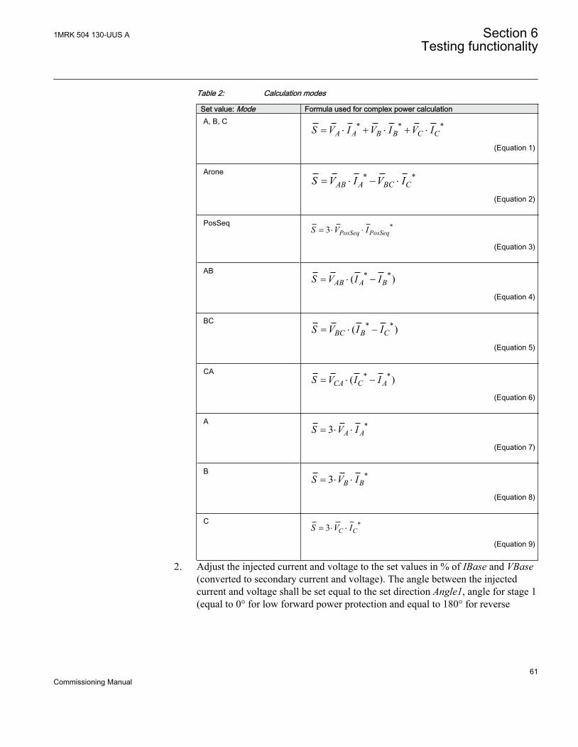
Table 2: Calculation modes
Set value: Mode Formula used for complex power calculationA, B, C * * *
A A B B C CS V I V I V I= × + × + ×
EQUATION2055 V1 EN (Equation 1)
Arone * *AB A BC CS V I V I= × - ×
EQUATION2056-ANSI V1 EN (Equation 2)
PosSeq *3 PosSeq PosSeqS V I= × ×
EQUATION2057-ANSI V1 EN (Equation 3)
AB * *( )AB A BS V I I= × -
EQUATION2058-ANSI V1 EN (Equation 4)
BC * *( )BC B CS V I I= × -
EQUATION2059-ANSI V1 EN (Equation 5)
CA * *( )CA C AS V I I= × -
EQUATION2060-ANSI V1 EN (Equation 6)
A *3 A AS V I= × ×
EQUATION2061-ANSI V1 EN (Equation 7)
B *3 B BS V I= × ×
EQUATION2062-ANSI V1 EN (Equation 8)
C *3 C CS V I= × ×
EQUATION2063-ANSI V1 EN (Equation 9)
2. Adjust the injected current and voltage to the set values in % of IBase and VBase(converted to secondary current and voltage). The angle between the injectedcurrent and voltage shall be set equal to the set direction Angle1, angle for stage 1(equal to 0° for low forward power protection and equal to 180° for reverse
1MRK 504 130-UUS A Section 6Testing functionality
61Commissioning Manual

power protection). Check that the monitored active power is equal to 100% ofrated power and that the reactive power is equal to 0% of rated power.
3. Change the angle between the injected current and voltage to Angle1 + 90°.Check that the monitored active power is equal to 0% of rated power and that thereactive power is equal to 100% of rated power.
4. Change the angle between the injected current and voltage back to 0°. Decreasethe current slowly until the PICKUP1 signal, pickup of stage 1, is activated.
5. Increase the current to 100% of IBase.6. Switch the current off and measure the time for activation of TRIP1, trip of stage
1.7. If a second stage is used, repeat steps 2 to 6 for the second stage.
6.4.8.2 Completing the test
Continue to test another function or end the testing by setting the parameter TestModeto Disabled under Main menu/Tests/IED test mode/1:TESTMODE. If anotherfunction is tested, then set the parameter Blocked to No under Main menu/Tests/Function test modes/Current/GUPPDUP(37,P<)/1:GUPPDUP for the function, orfor each individual function in a chain, to be tested next. Remember to set theparameter Blocked to Yes, for each individual function that has been tested.
6.4.9 Directional overpower protection GOPPDOP (32)Prepare the IED for verification of settings as outlined in 5.1 "Preparing the IED toverify settings".
Values of the logical signals for GOPPDOP (32) are available on the local HMI underMain menu/Tests/Function status/Current/GOPPDOP(32,P>)/X:GOPPDOP. TheSignal Monitoring in PCM600 shows the same signals that are available on the local HMI.
6.4.9.1 Verifying the settings
The overpower protection shall be set to values according to the real set values to beused. The test is made by means of injection of voltage and current where theamplitude of both current and voltage and the phase angle between the voltage andcurrent can be controlled. During the test the analog outputs of active and reactivepower shall be monitored.
1. Connect the test set for injection of voltage and current corresponding to themode to be used in the application. If a three phase test set is available this couldbe used for all the modes. If a single phase current/voltage test set is available thetest set should be connected to a selected input for one phase current and voltage.
Section 6 1MRK 504 130-UUS ATesting functionality
62Commissioning Manual

Use the formulas stated in Table 2 for the different calculation modes used. Theset mode Mode can be found under Main menu/Settings/IED Settings/Current/GOPPDOP(32,P>)/1:GOPPDOP/General.
2. Adjust the injected current and voltage to the set rated values in % of IBase andVBase (converted to secondary current and voltage). The angle between theinjected current and voltage shall be set equal to the set direction Angle1, anglefor stage 1 (equal to 0° for low forward power protection and equal to 180° forreverse power protection). Check that the monitored active power is equal to100% of rated power and that the reactive power is equal to 0% of rated power.
3. Change the angle between the injected current and voltage to Angle1 + 90°.Check that the monitored active power is equal to 0% of rated power and that thereactive power is equal to 100% of rated power.
4. Change the angle between the injected current and voltage back to Angle1 value.Increase the current slowly from 0 until the PICKUP1 signal, pickup of stage 1, isactivated. Check the injected power and compare it to the set value Power1,power setting for stage 1 in % of Sbase.
5. Increase the current to 100% of IBase and switch the current off.6. Switch the current on and measure the time for activation of TRIP1, trip of stage 1.7. If a second stage is used, repeat steps 2 to 6 for the second stage.
6.4.9.2 Completing the test
Continue to test another function or end the testing by setting the parameter TestModeto Disabled under Main menu/Tests/IED test mode/1:TESTMODE. If anotherfunction is tested, then set the parameter Blocked to No under Main menu/Tests/Function test modes/Current/GOPPDOP(32,P>)/X:GOPPDOP for the function, orfor each individual function in a chain, to be tested next. Remember to set theparameter Blocked to Yes, for each individual function that has been tested.
6.5 Testing voltage protection functions
6.5.1 Two step undervoltage protection UV2PTUV (27)Prepare the IED for verification of settings as outlined in 5.1 "Preparing the IED toverify settings".
Values of the logical signals for UV2PTUV (27) are available on the local HMI underMain menu/Tests/Function status/Voltage/UV2PTUV(27,2U<)/1:UV2PTUV. TheSignal Monitoring in PCM600 shows the same signals that are available on the local HMI.
1MRK 504 130-UUS A Section 6Testing functionality
63Commissioning Manual

6.5.1.1 Verifying the setting
Verification of PICKUP value and time delay to operate for Step1
1. Check that the IED settings are appropriate, especially the PICKUP value, thedefinite time delay and the 1 out of 3 operation mode.
2. Supply the IED with three-phase voltages at their rated values.3. Slowly decrease the voltage in one of the phases, until the PICKUP signal appears.4. Note the operate value and compare it with the set value.5. Increase the measured voltage to rated load conditions.6. Check that the PICKUP signal resets.7. Instantaneously decrease the voltage in one phase to a value about 20% lower
than the measured operate value.8. Measure the time delay for the TRIP signal, and compare it with the set value.
Extended testing
1. The test above can now be repeated for step 2.2. The tests above can be repeated for 2 out of 3 and for 3 out of 3 operation mode.3. The tests above can be repeated to check security, that is, the PICKUP and
operate signals, that are not supposed to appear, - do not.4. The tests above can be repeated to check the time to reset.5. The tests above can be repeated to test the inverse time characteristic.
6.5.1.2 Completing the test
Continue to test another function or end the testing by setting the parameter TestModeto Disabled under Main menu/Tests/IED test mode/1:TESTMODE. If anotherfunction is tested, then set the parameter Blocked to No under Main menu/Tests/Function test modes/Voltage/UV2PTUV(27,2U<)/1:UV2PTUV for the function, orfor each individual function in a chain, to be tested next. Remember to set theparameter Blocked to Yes, for each individual function that has been tested.
6.5.2 Two step overvoltage protection OV2PTOV (59)Prepare the IED for verification of settings as outlined in 5.1 "Preparing the IED toverify settings".
Values of the logical signals for OV2PTOV (59) are available on the local HMI underMain menu/Tests/Function status/Voltage/OV2PTOV(59,2U>)/1:OV2PTOV. TheSignal Monitoring in PCM600 shows the same signals that are available on the local HMI.
Section 6 1MRK 504 130-UUS ATesting functionality
64Commissioning Manual

6.5.2.1 Verifying the settings
1. Apply single-phase voltage below the set value Pickup1.2. Slowly increase the voltage until the PU_ST1 signal appears.3. Note the operate value and compare it with the set value.4. Switch the applied voltage off.5. Set and apply about 20% higher voltage than the measured operate value for one
phase.6. Measure the time delay for the TRST1 signal and compare it with the set value.7. Repeat the test for step 2.
6.5.2.2 Completing the test
Continue to test another function or end the testing by setting the parameter TestModeto Disabled under Main menu/Tests/IED test mode/1:TESTMODE. If anotherfunction is tested, then set the parameter Blocked to No under Main menu/Tests/Function test modes/Voltage/OV2PTOV(59,2U>)/1:OV2PTOV for the function, orfor each individual function in a chain, to be tested next. Remember to set theparameter Blocked to Yes, for each individual function that has been tested.
6.5.3 Two step residual overvoltage protection ROV2PTOV (59N)Prepare the IED for verification of settings as outlined in 5.1 "Preparing the IED toverify settings".
Values of the logical signals for ROV2PTOV (59N) are available on the local HMIunder Main menu/Tests/Function status/Voltage/ROV2PTOV(59N,2UN>)/1:ROV2PTOV. The Signal Monitoring in PCM600 shows the same signals that areavailable on the local HMI.
6.5.3.1 Verifying the settings
1. Apply the single-phase voltage either to a single-phase voltage input or to aresidual voltage input with the pickup value below the set value Pickup1.
2. Slowly increase the value until PU_ST1 appears.3. Note the operate value and compare it with the set value.4. Switch the applied voltage off.5. Set and apply about 20% higher voltage than the measured operate value for one
phase.6. Measure the time delay for the TRST1 signal and compare it with the set value.7. Repeat the test for step 2.
1MRK 504 130-UUS A Section 6Testing functionality
65Commissioning Manual

6.5.3.2 Completing the test
Continue to test another function or end the testing by setting the parameter TestModeto Disabled under Main menu/Tests/IED test mode/1:TESTMODE. If anotherfunction is tested, then set the parameter Blocked to No under Main menu/Tests/Function test modes/Voltage/ROV2PTOV(59N,2UN>)/1:ROV2PTOV for thefunction, or for each individual function in a chain, to be tested next. Remember to setthe parameter Blocked to Yes, for each individual function that has been tested.
6.5.4 Overexcitation protection OEXPVPH (24)Prepare the IED for verification of settings as outlined in 5.1 "Preparing the IED toverify settings".
Values of the logical signals for OEXPVPH (24) are available on the local HMI underMain menu/Tests/Function status/Voltage/OEXPVPH(24,U/f>)/1:OEXPVPH. TheSignal Monitoring in PCM600 shows the same signals that are available on the local HMI.
6.5.4.1 Verifying the settings
1. Enable function.2. Connect a symmetrical three-phase voltage input from the test set to the
appropriate connection terminals of the overexcitation protection OEXPVPH(24).OEXPVPH (24) is conveniently tested using rated frequency for the injectionvoltage and increasing the injection voltage to get the desired overexcitation level.
3. Connect the alarm contact to the timer and set the time delay tAlarm temporarilyto zero.
4. Increase the voltage and note the operate value Pickup1.5. Reduce the voltage slowly and note the reset value.6. Set the alarm time delay to the correct value according to the setting plan and
check the time delay, injecting a voltage corresponding to 1.2 · Pickup1.7. Connect a trip output contact to the timer and temporarily set the time delay
t_MinTripDelay to 0.5s.8. Increase the voltage and note the Pickup2 operate value9. Reduce the voltage slowly and note the reset value.10. Set the time delay to the correct value according to the setting plan and check the
time delay t_MinTripDelay, injecting a voltage corresponding to 1.2 · Pickup2.11. Check that trip and alarm contacts operate according to the configuration logic.12. Finally check that PICKUP and TRIP information is stored in the event menu.
Section 6 1MRK 504 130-UUS ATesting functionality
66Commissioning Manual
6.5.4.2 Completing the test
Continue to test another function or end the testing by setting the parameter TestModeto Disabled under Main menu/Tests/IED test mode/1:TESTMODE. If anotherfunction is tested, then set the parameter Blocked to No under Main menu/Tests/Function test modes/Voltage/OEXPVPH(24,U/f>)/1:OEXPVPH for the function, orfor each individual function in a chain, to be tested next. Remember to set theparameter Blocked to Yes, for each individual function that has been tested.
6.6 Testing frequency protection functions
6.6.1 Underfrequency protection SAPTUF (81)Prepare the IED for verification of settings as outlined in 5.1 "Preparing the IED toverify settings".
Values of the logical signals for SAPTUF (81) are available on the local HMI underMain menu/Tests/Function status/Frequency/SAPTUF(81,f<)/X:SAPTUF. TheSignal Monitoring in PCM600 shows the same signals that are available on the local HMI.
6.6.1.1 Verifying the settings
Verification of PICKUP value and time delay to operate
1. Check that the IED settings are appropriate, especially the PICKUP value and thedefinite time delay.
2. Supply the IED with three-phase voltages at their rated values.3. Slowly decrease the frequency of the applied voltage, until the PICKUP signal
appears.4. Note the operate value and compare it with the set value.5. Increase the frequency until rated operating levels are reached.6. Check that the PICKUP signal resets.7. Instantaneously decrease the frequency of the applied voltage to a value about
20% lower than the operate value.8. Measure the time delay of the TRIP signal, and compare it with the set value.
Extended testing
1. The test above can be repeated to check the time to reset.2. The tests above can be repeated to test the frequency dependent inverse time
characteristic.
1MRK 504 130-UUS A Section 6Testing functionality
67Commissioning Manual

Verification of the low voltage magnitude blocking
1. Check that the IED settings are appropriate, especially the PUFrequency and thetDelay and the MinValFreqMeas in the SMAI preprocessing function.
2. Supply the IED with three-phase voltages at rated values.3. Slowly decrease the magnitude of the applied voltage, until the BLKDMAGN
signal appears.4. Note the voltage magnitude value and compare it with the SMAI set value
MinValFreqMeas.5. Slowly decrease the frequency of the applied voltage, to a value below
PUFrequency.6. Check that the PICKUP signal does not appear.7. Wait for a time corresponding to tDelay, and check that the TRIP signal does not
appear.
6.6.1.2 Completing the test
Continue to test another function or end the testing by setting the parameter TestModeto Disabled under Main menu/Tests/IED test mode/1:TESTMODE. If anotherfunction is tested, then set the parameter Blocked to No under Main menu/Tests/Function test modes/Frequency/SAPTUF(81,f<)/X:SAPTUF for the function, or foreach individual function in a chain, to be tested next. Remember to set the parameterBlocked to Yes, for each individual function that has been tested.
6.6.2 Overfrequency protection SAPTOF (81)Prepare the IED for verification of settings as outlined in 5.1 "Preparing the IED toverify settings".
Values of the logical signals for SAPTOF (81) are available on the local HMI underMain menu/Tests/Function status/Frequency/SAPTOF(81,f>)/X:SAPTOF. TheSignal Monitoring in PCM600 shows the same signals that are available on the local HMI.
6.6.2.1 Verifying the settings
Verification of PICKUP value and time delay to operate
1. Check that the settings in the IED are appropriate, especially the PICKUP valueand the definite time delay.
2. Supply the IED with three-phase voltages at their rated values.3. Slowly increase the frequency of the applied voltage, until the PICKUP signal
appears.4. Note the operate value and compare it with the set value.
Section 6 1MRK 504 130-UUS ATesting functionality
68Commissioning Manual

5. Decrease the frequency to rated operating conditions.6. Check that the PICKUP signal resets.7. Instantaneously increase the frequency of the applied voltage to a value about
20% higher than the operate value.8. Measure the time delay for the TRIP signal, and compare it with the set value.
Extended testing
1. The test above can be repeated to check the time to reset.
Verification of the low voltage magnitude blocking
1. Check that you have appropriate settings in the IED, especially the PUFrequency,TtDelay and the MinValFreqMeas in the SMAI preprocessing function
2. Supply the IED with three-phase voltages at their rated values.3. Slowly decrease the magnitude of the applied voltage, until the BLKDMAGN
signal appears.4. Note the voltage magnitude value and compare it with the set value,
MinValFreqMeas.5. Slowly increase the frequency of the applied voltage, to a value above
PUFrequency.6. Check that the PICKUP signal does not appear.7. Wait for a time corresponding to tDelay, and make sure that the TRIP signal does
not appear.
6.6.2.2 Completing the test
Continue to test another function or end the testing by setting the parameter TestModeto Disabled under Main menu/Tests/IED test mode/1:TESTMODE. If anotherfunction is tested, then set the parameter Blocked to No under Main menu/Tests/Function test modes/Frequency/SAPTOF(81,f>)/X:SAPTOF for the function, or foreach individual function in a chain, to be tested next. Remember to set the parameterBlocked to Yes, for each individual function that has been tested.
6.6.3 Rate-of-change frequency protection SAPFRC (81)Prepare the IED for verification of settings as outlined in 5.1 "Preparing the IED toverify settings".
Values of the logical signals for SAPFRC (81) are available on the local HMI underMain menu/Tests/Function status/Frequency/SAPFRC(81,df/dt)/X:SAPFRC. TheSignal Monitoring in PCM600 shows the same signals that are available on the local HMI.
1MRK 504 130-UUS A Section 6Testing functionality
69Commissioning Manual

6.6.3.1 Verifying the settings
PICKUP value and time delay to operate
1. Check that the appropriate settings are available in the IED, especially thePICKUP value and the definite time delay. Set PickupFreqgrad, to a rather smallnegative value.
2. Supply the IED with three-phase voltages at their rated values.3. Slowly decrease the frequency of the applied voltage, with an increasing rate-of-
change that finally exceeds the setting of PickupFreqgrad, and check that thePICKUP signal appears.
4. Note the operate value and compare it with the set value.5. Increase the frequency to rated operating conditions, and zero rate-of-change.6. Check that the PICKUP signal resets.7. Instantaneously decrease the frequency of the applied voltage to a value about
20% lower than the nominal value.8. Measure the time delay for the TRIP signal, and compare it with the set value.
Extended testing
1. The test above can be repeated to check a positive setting of PickupFreqGrad.2. The tests above can be repeated to test the RESTORE signal, when the frequency
recovers from a low value.
6.6.3.2 Completing the test
Continue to test another function or end the testing by setting the parameter TestModeto Disabled under Main menu/Tests/IED test mode/1:TESTMODE. If anotherfunction is tested, then set the parameter Blocked to No under Main menu/Tests/Function test modes/Frequency/SAPFRC(81,df/dt)/X:SAPFRC for the function, orfor each individual function in a chain, to be tested next. Remember to set theparameter Blocked to Yes, for each individual function that has been tested.
6.7 Testing control functions
During periods of frequent counter state/value changes, if the auxiliarypower to the IED is interrupted, it is possible that this information willbe lost.
Section 6 1MRK 504 130-UUS ATesting functionality
70Commissioning Manual

6.7.1 Voltage controlPrepare the IED for verification of settings as outlined in 5.1 "Preparing the IED toverify settings".
Values of the logical signals for TCMYLTC (84) are available on the local HMI underMain menu/Tests/Function status/Control/TCMYLTC(84)/X:TCMYLTC. TheSignal Monitoring in PCM600 shows the same signals that are available on the local HMI.
Values of the logical signals for TR8ATCC (90) are available on the local HMI underMain menu/Tests/Function status/Control/TR8ATCC(90)/X:TR8ATCC. TheSignal Monitoring in PCM600 shows the same signals that are available on the local HMI.
The automatic voltage control for tap changer, parallel control TR8ATCC (90), ifinstalled, may be set to operate in Master Follower (MF) mode, or MinimiseCirculating Current (CC) mode. The commissioning tests for each parallel controlmode are addressed separately in the following procedure.
Secondary injection of load current (IL) and secondary bus voltage (UB) equivalentquantities are required during installation and commissioning tests. The test consistsmainly of:
1. Increasing or decreasing the injected voltage or current at the analogue inputs ofthe IED.
2. Checking that the corresponding commands (Lower or Raise) are issued by thevoltage control function.
Setting confirmation is an important step for voltage control in the installation andcommissioning phase to ensure consistency of power systems base quantities, alarm/blocking conditions and parallel control settings for each transformer control function.
Before starting any test, verify the following settings in PCM600 or the local HMI forTR8ATCC (90) and TCMYLTC (84).
• Confirm power system base quantities IBase (for winding 1, which is defined in aglobal base function, selected with setting GlobalBaseSel1 for TR8ATCC, 90),IBase (for winding 2, which is defined in a global base function, selected withsetting GlobalBaseSel2 for TR8ATCC, 90), VBase.
Main menu/Settings/IED Settings/Control/TR8ATCC (90)/TR8ATCC/General
and
Main menu/Settings/IED Settings/Control/TCMYLTC (84)
.
1MRK 504 130-UUS A Section 6Testing functionality
71Commissioning Manual

• Confirm that the setting for short circuit impedance Xr2 for TR8ATCC (90) is inaccordance with transformer data:• Short circuit impedance, available on the local HMI under Main menu/
Settings/IED Settings/Control/TR8ATCC (90)/1:TR8ATCC/General/Xr2.
• Confirm that the setting for TCMYLTC (84) is in accordance with transformer data:• Tap change timeout duration - effectively the maximum transformer tap
change time, tTCTimeout, available on the local HMI under Main menu/Settings/IED Settings/Control/TCMYLTC (84)/1:TCMYLTC/tTCTimeout.
• Load tap changer pulse duration - required length of pulse from IED to loadtap changer, tPulseDur, available on the local HMI under Main menu/Settings/IED Settings/Control/TCMYLTC (84)/1:TCMYLTC/tPulseDur.
• Transformer tap range, LowVoltTap and HighVoltTap, available on the localHMI under Main menu/Settings/IED Settings/Control/TCMYLTC (84)/1:TCMYLTC/LowVoltTap and Main menu/Settings/IED Settings/Control/TCMYLTC (84)/1:TCMYLTC/HighVoltTap.
• Load tap changer code type - method for digital feedback of tap position,CodeType, available on the local HMI under Main menu/Settings/IEDSettings/Control/TCMYLTC (84)/1:TCMYLTC/CodeType.
During the installation and commissioning, the behavior of the voltagecontrol functions for different tests may be governed by a parametergroup, available on the local HMI under Main menu/Settings/IEDSettings/Control/TR8ATCC/1:TR8ATCC/General. These parametersettings can cause a Total Block, Automatic Block or Alarm for avariety of system conditions including over and under voltage, overcurrent and tap changer failure. It is important to review these settingsand confirm the intended response of the voltage control function fordifferent secondary injection tests.
TerminologyThe busbar voltage VB is a shorter notation for the measured voltages Va, Vb, Vc orVij, where Vij is the phase-phase voltage, Vij = Vi -Vj, or Vi, where Vi is one single-phase-to-ground voltage.
IL is a shorter notation for the measured load current; it is to be used instead of the three-phase quantities Ia, Ib, Ic or the two-phase quantities Ii and Ij, or single-phase current Ii.
Section 6 1MRK 504 130-UUS ATesting functionality
72Commissioning Manual
Also note that, for simplicity, local HMI menu structures included in the followingprocedure are referred to universally as TR8ATCC (90), for example, Main menu/Settings/IED Settings/Control/TR8ATCC/1:TR8ATCC/Time/t1.
6.7.1.1 Secondary test
The voltage control function performs basic voltage regulation by comparing acalculated load voltage (VL) against a voltage range defined by setting VDeadband(with upper and lower limits V2 and V1 respectively). The calculated load voltage VLrepresents the secondary transformer bus voltage VB adjusted for Load dropcompensation (LDC) where enabled in settings.
Note that when LDC is disabled, VB equals VL.
When the load voltage VL stays within the interval between V1 and V2, no action willbe taken.
If VL < V1 or VL > V2, a command timer will start, which is constant time or inversetime defined by setting t1 and t1Use. The command timer will operate while themeasured voltage stays outside the inner deadband (defined by settingVDeadbandInner).
If VL remains outside of the voltage range defined by VDeadband and the commandtimer expires, the voltage control will execute a raise or lower command to thetransformer tap changer. This command sequence will be repeated until VL is broughtback within the inner deadband range.
6.7.1.2 Check the activation of the voltage control operation
1. Confirm Transformer Tap Control = Enable and Transformer Voltage Control =Enable• Direct tap change control
Main menu/Settings/IED Settings/Control/TCMYLTC (84)/1:TCMYLTC/Operation• Automatic transformer voltage control
Main menu/Settings/IED Settings/Control• Enable Tap Command
1MRK 504 130-UUS A Section 6Testing functionality
73Commissioning Manual

Commands to tap changer are enabled per default.While the test set is connected to the IED but no voltage is applied, the voltagecontrol functions will detect an undervoltage condition that may result in analarm or blocking of the voltage-control operation. These conditions will beshown on the local HMI.
2. Apply the corresponding voltageConfirm the analog measuring mode prior to undertaking secondary injection(positive sequence, phase-phase, or phase-ground). This measuring mode isdefined in the local HMI under Main menu/Settings/IED Settings/Control/TR8ATCC (90)/1:TR8ATCC/General/MeasModeThe application of nominal voltage VSet according to set MeasMode to the IEDsshould cause the alarm or blocking condition for undervoltage to reset.
6.7.1.3 Check the normal voltage regulation function
1. Review the settings for VDeadband (based on percentage of nominal bus voltage)and calculate the upper (V2) and lower (V1) voltage regulation limits for which atap change command will be issued.
2. Review the expected time for first (t1) and subsequent (t2) tap change commandsfrom the voltage control function on the local HMI under Main menu/Settings/IED Settings/Control/TR8ATCC (90)/1:TR8ATCC/Time/t1 and t2
3. Lower the voltage 1% below V1 and wait for the issue of a Raise command fromthe voltage control after the expiry of a constant or inverse time delay set by t1.Detection of this command will involve locating the allocated binary output for araise pulse command in the Signal Matrix in PCM600 and monitoring a positivefrom this output.
4. After the issue of the raise command, return the applied voltage to VSet (nominalvalue).
5. Raise the voltage 1% above the upper deadband limit V2 and wait for the issue ofa lower command from the voltage control after the expiry of a constant orinverse time delay set by t1. Detection of this command will involve locating theallocated binary output for a low pulse command in the Signal Matrix in PCM600and monitoring a positive from this output.
6. Return the applied voltage to VSet.
6.7.1.4 Check the undervoltage block function
1. Confirm the setting for Vblock, nominally at 80% of rated voltage.2. Confirm the voltage control function response to an applied voltage below
Vblock, by reviewing the setting in the local HMI under Main menu/Settings/IED Settings/Control/TR8ATCC (90)/1:TR8ATCC/General/UVBk that may
Section 6 1MRK 504 130-UUS ATesting functionality
74Commissioning Manual

cause an alarm, total or automatic block of the voltage control function to bedisplayed on the local HMI.
3. Apply a voltage slightly below Vblock and confirm the response of the voltagecontrol function.
6.7.1.5 Check the upper and lower busbar voltage limit
1. Confirm the settings for Vmin and Vmax in the local HMI under Main menu/Settings/IED Settings/Control//TR8ATCC (90)/n:TR8ATCC/Voltage/Uminand Main menu/Settings/IED Settings/Control/TR8ATCC (90)/n:TR8ATCC/Voltage/Umax
2. Confirm the voltage control function response to an applied voltage below Vminand above Vmax, by reviewing the settings in the local HMI under Main menu/Settings/IED Settings/Control/TR8ATCC (90)/n:TR8ATCC/General/UVPartBk and Main menu/Settings/IED Settings/Control/TR8ATCC (90)/n:TR8ATCC/General/OVPartBk.
3. Decrease the injected voltage slightly below the Vmin value and check for thecorresponding blocking or alarm condition on the local HMI. For an alarmcondition, the voltage regulation function is not blocked and a raise commandshould be issued from the IED.
4. Increase the applied voltage slightly above the Vmax value and check for thecorresponding blocking or alarm condition on the local HMI. For an alarmcondition, the voltage regulation function is not blocked and a lower commandshould be issued from the IED.
6.7.1.6 Check the overcurrent block function
1. Confirm the setting for Iblock in the local HMI under Main menu/Settings/IEDSettings/Control/TR8ATCC (90)/n:TR8ATCC/TCCtrl/Iblock
2. Confirm the voltage control function response to an applied current above Iblock,by reviewing the settings in the local HMI under Main menu/Settings/IEDSettings/Control/TR8ATCC (90)/n:TR8ATCC/General/OCBk.
3. Inject a current higher than the Iblock setting and confirm the alarm or blockingcondition is present on the local HMI. If an automatic or total blocking conditionoccurs, change the applied secondary voltage and confirm that no tap changecommands are issued from the associated binary outputs. This situation can alsobe confirmed through reviewing the disturbance and service reports on the localHMI.
1MRK 504 130-UUS A Section 6Testing functionality
75Commissioning Manual

6.7.1.7 Automatic voltage control for tap changer, parallel control TR8ATCC
Master follower voltage regulation
1. For the transformers connected in the parallel group, confirm that OperationPARis set to MF.
2. For parallel operation, it is also recommended to confirm for parallel groupmembership, defined by setting TnRXOP in the local HMI under Main menu/Settings/IED Settings/Control/TR8ATCC (90)/n:TR8ATCC/ParCtrlThe general parallel arrangement of transformers are defined by setting TnRXOPto Enabled or Disabled. The following rules are applicable on the settingsT1RXOP – T4RXOP.If IED T1 and T2 are connected,• T1RXOP shall be set to Enabled in instance 2 of TR8ATCC (90),• T2RXOP shall be set to Enabled in instance 3 of TR8ATCC (90),• T2RXOP and T3RXOP shall be set to Enabled in instance 1 of TR8ATCC
(90), and so on.
The parameter corresponding to the own IED must not be set.T1RXOP should thus not be set in IED T1, T2RXOP not in IEDT2, and so on.
3. The lowest transformer number in the parallel group is by default set as theMaster – confirm that this is the case by reviewing the setting in the local HMI.
4. Review the settings for VDeadband (based on percentage of nominal bus voltage)and calculate the upper (V2) and lower (V1) voltage regulation limits for which atap change command will be issued from the master transformer in the group.
5. Apply a voltage 1% below V1 and wait for the issue of a raise command from thevoltage control after the expiry of a constant or inverse time delay set by t1.Detection of this command will involve locating the allocated binary output for araise command in the Signal Matrix in PCM600 and monitoring a positive fromthis output. Confirm the timing of this command correlates with the setting t1.
6. After the issue of the raise command, confirm that all follower transformers in thegroup change tap in accordance with the command issued from the mastertransformer.
7. Inject a voltage VB for the master transformer that is 1% above the upperdeadband limit V2 and wait for the issue of a lower command from the voltagecontrol after the expiry of a constant or inverse time delay set by t2.
8. Confirm that all follower transformers in the group change tap in accordance withthis command.
Section 6 1MRK 504 130-UUS ATesting functionality
76Commissioning Manual

Circulating current voltage regulationThis instruction for confirmation of circulating current voltage regulation assumes twotransformers in the parallel group. Setting confirmation through secondary injectionrequires calculation of circulating currents for each transformer based on impedancevalues and respective compensating factors, and is therefore more complex for greaterthan two transformers.
1. Confirm that OperationPAR is set to CC for the transformers in the parallel group.2. For parallel operation, it is also recommended that settings be confirmed for
parallel group membership, governed by setting TnRXOP in the local HMI underMain menu/Setting/IED Setting/Control/TR8ATCC (90)/n:TR8ATCC/ParCtrlThe general parallel arrangement of transformers are defined by setting TnRXOPto Enabled or Disabled. The following rules are applicable on the settingsT1RXOP - T4RXOP.If IED T1 and T2 are connected,• T1RXOP shall be set to Enabled in instance 2 of TR8ATCC (90), and• T2RXOP shall be set to Enabled in instance 1 of TR8ATCC (90).
If T1 - T3 are available,• T1RXOP and T2RXOP shall be set to Enabled in instance 3 of TR8ATCC
(90),• T2RXOP and T3RXOP shall be set to Enabled in instance 1 of TR8ATCC
(90) and so on.
The parameter corresponding to the own IED must not be set.T1RXOP should thus not be set in IED T1, T2RXOPnot in IED T2and so on.
3. Review the settings for VDeadband (based on percentage of nominal bus voltage)and calculate the upper (V2) and lower (V1) voltage regulation limits for which atap change command will be issued from the master transformer in the group.
4. Inject a voltage VB equal to VSet for each transformer.5. Inject a load current for Transformer 1 that is equal to rated load current IBase
(for winding 2, which is defined in a global base function, selected with settingGlobalBaseSel2 for TR8ATCC, 90) and a load current for Transformer 2 that isequal to 95% of rated load current IBase (for winding 2, which is defined in aglobal base function, selected with setting GlobalBaseSel2 for TR8ATCC (90)).This will have the effect of producing a calculated circulating current that flowsfrom HV to LV side for Transformer 1 and LV to HV side for Transformer 2.
6. Confirm that a circulating current is measured on the local HMI that is equal inmagnitude to 5% of IBase (for winding 2, which is defined in a global base
1MRK 504 130-UUS A Section 6Testing functionality
77Commissioning Manual

function, selected with setting GlobalBaseSel2 for TR8ATCC (90)), with polarityas discussed in step 5.
7. Confirm the settings for Ci (Compensation Factor) and Xi (Transformer ShortCircuit Impedance). Using these setting values and the measured quantity ofcirculating current from the local HMI (Icc_i), calculate the value for circulatingcurrent voltage adjustment Vci.
_Vdi Ci Icc i Xi= × ×EQUATION2089-ANSI V1 EN (Equation 10)
The voltage regulation algorithm then increases (for transformer T2) or decreases(for transformer T1) the measured voltage by Vdi and compares Vi against thevoltage deadband limits V1 and V2 for the purposes of voltage regulation.
Vi VB Vdi= +EQUATION2091-ANSI V1 EN (Equation 11)
8. To cause a tap change, the calculated value for circulating current voltageadjustment must offset the injected quantity for bus voltage VB so that Vi isoutside the voltage deadband created by setting VDeadband. Expressed byequation 12 and equation 13.
2Vdi V VB> -EQUATION2093-ANSI V1 EN (Equation 12)
VB Vset=EQUATION2095-ANSI V1 EN (Equation 13)
(for the purposes of this test procedure)
Therfore:
_ 2Ci Icc i Xi V Vset× × > -EQUATION2097-ANSI V1 EN (Equation 14)
( )( )
2_
V VsetIcc i Ci Xi-
>×
EQUATION2099-ANSI V1 EN (Equation 15)
Section 6 1MRK 504 130-UUS ATesting functionality
78Commissioning Manual

9. Using the settings for VSet, VDeadband, C (Compensating factor) and Xr2(transformer short circuit impedance) calculate the magnitude of Icc_i necessaryto cause a tap change command.
10. Inject current equal to IBase (for winding 2, which is defined in a global basefunction, selected with setting GlobalBaseSel2 for TR8ATCC, 90) forTransformer 1 and (IBase - |Icc_i|) for Transformer 2 so that the magnitude ofcalculated circulating current will cause a raise command to be issued forTransformer 2 and a lower command for Transformer 1. Magnitude and directionof circulating currents measured for each transformer can be observed as servicevalues on the local HMI and raise/lower commands detected from the binaryoutput mapped in the Signal Matrix.
The voltage injection equal to VSet is required for bothtransformers during this test.
11. Confirm that a tap change command is issued from the voltage control function tocompensate for the circulating current.
12. Injected currents can be reversed such that the direction of calculated circulatingcurrents change polarity, which will cause a lower command for Transformer 2and a raise command for Transformer 1.
Circulating current limit
1. Confirm that OperationPAR is set to CC for each transformer in the parallel group.2. Confirm that OperCCBlock is set to Enable for each transformer in the parallel
group.3. Review the setting for CircCurrLimit.4. Review the setting for CircCurrBk to confirm whether a circulating current limit
will result in an Alarm state, Auto Block or Auto&Man Block of the automaticvoltage control for tap changer, for parallel control function TR8ATCC (90).
5. Inject a voltage VB equal to VSet for each transformer.6. Inject a load current for Transformer 1 that is equal to rated load current IBase
(for winding 2, which is defined in a global base function, selected with settingGlobalBaseSel2 for TR8ATCC (90)) and a load current for Transformer 2 that is1% less than (IBase – (IBase · CircCurrLimit))
7. Confirm that the automatic voltage control for tap changer, for parallel controlfunction TR8ATCC (90) responds in accordance with the setting for CircCurrBk.Alarm and blocking conditions can be confirmed through interrogation of theevent menu or the control menu on the local HMI.
VTmismatch during parallel operation
1MRK 504 130-UUS A Section 6Testing functionality
79Commissioning Manual

1. Confirm that OperationPAR is set to MF for each transformer in the parallel group.2. Review the setting for VTmismatch and tVTmismatch.3. Inject a voltage VB equal to VSet for Transformer 1 and a voltage less than (VSet
– (VTmismatch · VSet)) for Transformer 2.4. This condition should result in a VTmismatch which will mutually block the
operation of the automatic voltage control for tap changer, parallel controlfunction TR8ATCC (90) for all transformers connected in the parallel group,which can be confirmed through interrogation of the local HMI.
5. Confirm that the automatic voltage control for tap changer, parallel controlfunction TR8ATCC (90) responds in accordance with the setting for CircCurrBk.
6.7.1.8 Completing the test
Continue to test another function or end the testing by setting the parameter TestModeto Disabled under Main menu/Tests/IED test mode/1:TESTMODE. If anotherfunction is tested, then set the parameter Blocked to No under Main menu/Tests/Function test modes/Control/TR8ATCC(90)/X:TR8ATCC for the function, or foreach individual function in a chain, to be tested next. Remember to set the parameterBlocked to Yes, for each individual function that has been tested.
6.8 Testing logic functions
6.8.1 Tripping logic, common 3-phase output SMPPTRC (94)Prepare the IED for verification of settings as outlined in 5.1 "Preparing the IED toverify settings".
Values of the logical signals for SMPPTRC (94) are available on the local HMI underMain menu/Tests/Function status/Logic/SMPPTRC(94,1->0)/X:SMPPTRC. TheSignal Monitoring in PCM600 shows the same signals that are available on the local HMI.
This function is functionality tested together with other protection functions (ground-fault overcurrent protection, and so on) within the IED. It is recommended that thefunction is tested together with the autorecloser function, regardless of whether theautorecloser function is integrated or external.
6.8.1.1 Three-phase operating mode
1. Check that AutoLock and TripLockout are both set to Disabled.2. Initiate a three-phase fault.
Section 6 1MRK 504 130-UUS ATesting functionality
80Commissioning Manual

An adequate time interval between the faults should be considered, to overcomeareset time caused by the possible activation of the Autorecloser function,SMBRREC (79). The function must issue a three-pole trip in all cases, when atrip is initiated by any protection function, either integrated or external. Thefunctional TRIP output signal must always appear.
6.8.1.2 Circuit breaker lockout
The following tests should be carried out when the built-in lockout function is used inaddition to possible other tests, which depends on the complete configuration of anIED.
1. Check that AutoLock and TripLockout are both set to Disabled.2. Initiate a three-phase fault.
The functional output TRIP should be active at each fault. The output CLLKOUTmust not be activated.
3. Activate the automatic lockout function, set AutoLock = Enabled and repeat.Besides the TRIP outputs, CLLKOUT should be set.
4. Reset the lockout signal by activating the reset lockout (RSTLKOUT) signal.5. Activate the TRIP signal lockout function, set TripLockout = Enable and repeat.
The output TRIP must be active and stay active after each fault. CLLKOUT mustbe activated.
6. Reset the lockout.All functional outputs should reset.
7. Deactivate the TRIP signal lockout function, set TripLockout = Disabled and theautomatic lockout function, set AutoLock = Disabled if not used.
6.8.1.3 Completing the test
Continue to test another function or end the testing by setting the parameter TestModeto Disabled under Main menu/Tests/IED test mode/1:TESTMODE. If anotherfunction is tested, then set the parameter Blocked to No under Main menu/Tests/Function test modes/Logic/SMPPTRC(94,1->0)/X:SMPPTRC for the function, orfor each individual function in a chain, to be tested next. Remember to set theparameter Blocked to Yes, for each individual function that has been tested.
6.9 Testing monitoring functions
6.9.1 Event counter CNTGGIOThe event counter function CNTGGIO can be tested by connecting a binary input tothe counter under test and applying pulses to the counter. The speed of pulses must not
1MRK 504 130-UUS A Section 6Testing functionality
81Commissioning Manual

exceed 10 per second. Normally the counter will be tested in connection with tests onthe function that the counter is connected to, such as trip logic. When configured, test ittogether with the function that operates it. Trig the function and check that the counterresult corresponds with the number of operations.
6.10 Testing metering functions
6.10.1 Pulse counter PCGGIOThe test of the Pulse counter function PCGGIO requires the Parameter Setting tool inPCM600 or an appropriate connection to the local HMI with the necessaryfunctionality. A known number of pulses with different frequencies are connected tothe pulse counter input. The test should be performed with settings Operation = Enableor Operation = Disable and the function blocked or unblocked. The pulse countervalue is then checked in PCM600 or on the local HMI.
6.11 Exit test mode
The following procedure is used to return to normal operation.
1. Navigate to the test mode folder.2. Change the Enable setting to Disable. Press the 'E' key and the left arrow key.3. Answer YES, press the 'E' key and exit the menus.
Section 6 1MRK 504 130-UUS ATesting functionality
82Commissioning Manual

Section 7 Commissioning and maintenance of thefault clearing system
7.1 Commissioning and maintenance of the fault clearingsystem
About this chapterThis chapter discusses maintenance tests and other periodic maintenance measures.
7.1.1 Commissioning testsDuring commissioning all protection functions shall be verified with the setting valuesused at each plant. The commissioning tests must include verification of all circuits byhighlighting the circuit diagrams and the configuration diagrams for the used functions.
Further, the settings for protection functions are tested and recorded carefully asoutlined for the future periodic maintenance tests.
The final testing includes primary verification of all directional functions where loadcurrents is checked on the local HMI and in PCM600. The magnitudes and angles ofall currents and voltages should be checked and the symmetry verified.
Directional functions have information about the measured direction and, for example,measured impedance. These values must be checked and verified as correct with theexport or import of power available.
Finally, final trip tests must be performed. This involves activation of protectionfunctions or tripping outputs with the circuit breaker closed and the tripping of thebreaker verified. When several breakers are involved, each breaker must be checkedindividually and it must be verified that the other involved breakers are not tripped atthe same time.
7.1.2 Periodic maintenance testsThe periodicity of all tests depends on several factors, for example the importance ofthe installation, environmental conditions, simple or complex equipment, static orelectromechanical IEDs, and so on.
1MRK 504 130-UUS A Section 7Commissioning and maintenance of the fault clearing system
83Commissioning Manual

The normal maintenance practices of the user should be followed. However, ABB'srecommendation is as follows:
Every second to third year
• Visual inspection of all equipment.• Removal of dust on ventilation louvres and IEDs if necessary.• Periodic maintenance test for protection IEDs of object where no redundant
protections are provided.
Every four to six years
• Periodic maintenance test for protection IEDs of objects with redundant protectionsystem.
First maintenance test should always be carried out after the first halfyear of service.
When protection IEDs are combined with built-in control, the testinterval can be increased drastically, up to for instance 15 years,because the IED continuously reads service values, operates thebreakers, and so on.
7.1.2.1 Visual inspection
Prior to testing, the protection IEDs should be inspected to detect any visible damagethat may have occurred (for example, dirt or moisture deposits, overheating). Shouldburned contacts be observed when inspecting the IEDs, a diamond file or an extremelyfine file can be used to polish the contacts. Emery cloth or similar products must not beused as insulating grains of abrasive may be deposited on the contact surfaces andcause failure.
Make sure that all IEDs are equipped with covers.
7.1.2.2 Maintenance tests
To be made after the first half year of service, then with the cycle as proposed aboveand after any suspected maloperation or change of the IED setting.
Testing of protection IEDs shall preferably be made with the primary circuit de-energized. The IED cannot protect the circuit during testing. Trained personnel may
Section 7 1MRK 504 130-UUS ACommissioning and maintenance of the fault clearing system
84Commissioning Manual

test one IED at a time on live circuits where redundant protection is installed and de-energization of the primary circuit is not allowed.
ABB protection IEDs are preferably tested by aid of components from theCOMBITEST testing system or FT test systems described in information B03-9510 E.Main components are RTXP 8/18/24 test switch located to the left in each protectionIED and RTXH 8/18/24 test handle, which is inserted in test switch at secondarytesting. All necessary operations such as opening of trip circuits, short-circuiting ofcurrent circuits and opening of voltage circuits are automatically performed in the rightorder to allow for simple and safe secondary testing even with the object in service.
Important components of FT test system are FT1, FTx, FT19, FT19RS, FR19RXswitches and assemblies as well as FT-1 test plug.
PreparationBefore starting maintenance testing, the test engineers should scrutinize applicablecircuit diagrams and have the following documentation available:
• Test instructions for protection IEDs to be tested• Test records from previous commissioning and maintenance tests• List of valid settings• Blank test records to fill in measured values
RecordingIt is of utmost importance to carefully record the test results. Special test sheetscovering the frequency of test, date of test and achieved test values should be used.IED setting list and protocols from previous tests should be available and all resultsshould be compared for differences. At component failures, spare equipment is usedand set to the requested value. A note of the exchange is made and the new measuredvalues are recorded. Test records for several years of testing should be stored in acommon file for a station, or a part of a station, to give a simple overview of the periodof testing and achieved test values. These test records are valuable when analysis ofservice disturbances shall be done.
Secondary injectionThe periodic maintenance test is done by secondary injection from a portable test set.Each protection shall be tested according to the secondary injection test information forthe specific protection IED. Only the setting values adopted shall be checked for eachprotection function. If the discrepancy between obtained value and requested set valueis too big the setting should be adjusted, the new value recorded and a note should bemade in the test record.
Alarm testWhen inserting the test handle of RTXP or using FT plugs, the alarm and eventsignalling is normally blocked. This is done in the IED by setting the event reporting to
1MRK 504 130-UUS A Section 7Commissioning and maintenance of the fault clearing system
85Commissioning Manual

Disabled during the test. This can be done when the test handle is inserted or the IEDis set to test mode from the local HMI. At the end of the secondary injection test itshould be checked that the event and alarm signalling is correct by activating theevents and performing some selected tests.
Self supervision checkOnce secondary testing has been completed, it should be checked that no self-supervision signals are activated continuously or sporadically. Especially check thetime synchronization system, GPS or other, and communication signals, both stationcommunication and remote communication.
Trip circuit checkWhen the protection IED undergoes an operational check, a tripping pulse is normallyobtained on one or more of the output contacts and preferably on the test switch. Thehealthy circuit is of utmost importance for the protection operation. If the circuit is notprovided with a continuous trip-circuit supervision, it is possible to check that circuit isreally closed when the test-plug handle has been removed by using a high-ohmicvoltmeter and measuring between the plus and the trip output on the panel. Themeasurement is then done through the tripping magnet of the circuit breaker andtherefore the complete tripping circuit is checked.
Note that the breaker must be closed.
Please observe that the test system does not provide built-in securityduring this test. If the instrument should be set on Amp instead ofVolts, the circuit breaker naturally is tripped, therefore, great care isnecessary.
Trip circuit from trip IEDs to circuit breaker is often supervised by trip-circuitsupervision. It can then be checked that a circuit is healthy by opening tripping outputterminals in the cubicle. When the terminal is opened, an alarm shall be achieved onthe signal system after a delay of some seconds.
Remember to close the circuit directly after the test and tighten theterminal carefully.
Measurement of service currentsAfter a maintenance test it is recommended to measure the service currents and servicevoltages recorded by the protection IED. The service values are checked on the local
Section 7 1MRK 504 130-UUS ACommissioning and maintenance of the fault clearing system
86Commissioning Manual

HMI or in PCM600. Ensure that the correct values and angles between voltages andcurrents are recorded. Also check the direction of directional functions such asDistance and directional overcurrent functions.
For transformer differential protection, the achieved differential current value isdependent on the tap changer position and can vary between less than 1% up toperhaps 10% of rated current. For line differential functions, the capacitive chargingcurrents can normally be recorded as a differential current.
The zero-sequence current to ground-fault protection IEDs should be measured. Thecurrent amounts normally very small but normally it is possible to see if the currentcircuit is "alive".
The neutral-point voltage to an ground-fault protection IED is checked. The voltage isnormally 0.1 to 1V secondary. However, voltage can be considerably higher due toharmonics. Normally a CVT secondary can have around 2.5 - 3% third-harmonic voltage.
RestoringMaintenance is very important to improve the availability of the protection system bydetecting failures before the protection is required to operate. There is however littlepoint in testing healthy equipment and then putting it back into service with an openterminal, with a removed fuse or open miniature circuit breaker with an openconnection, wrong setting, and so on.
Thus a list should be prepared of all items disturbed during test so that all can be putback into service quickly and without overlooking something. It should be put backinto service item by item and signed by the responsible engineer.
1MRK 504 130-UUS A Section 7Commissioning and maintenance of the fault clearing system
87Commissioning Manual

88

Section 8 Troubleshooting
8.1 Fault tracing
8.1.1 Identifying hardware errors
1. Check the module with an error.• Check the general IED status in Main menu/Diagnostics/IED status/
General for a faulty hardware module.• Check the history of changes in internal event list in Main menu/
Diagnostics/Internal Events.2. Inspect the IED visually.
• Inspect the IED visually to find any physical error causes.• If you can find some obvious physical damage, contact ABB for repair or
replacement actions.3. Check whether the error is external or internal.
• Check that the error is not caused by external origins.• Remove the wiring from the IED and test the input and output operation
with an external test device.• If the problem remains, contact ABB for repair or replacement actions.
8.1.2 Identifying runtime errors
1. Check the error origin from IED's internal event list Main menu/Diagnostics/IED status/General.
2. Reboot the IED and recheck the supervision events to see if the fault has cleared.3. In case of persistent faults, contact ABB for corrective actions.
8.1.3 Identifying communication errorsCommunication errors are normally communication interruptions or synchronizationmessage errors due to communication link breakdown.
1MRK 504 130-UUS A Section 8Troubleshooting
89Commissioning Manual
• Check the IEC61850 and DNP3 communication status in internal event list inMain menu/Diagnostics/IED Status/General.
• In case of persistent faults originating from IED's internal faults such ascomponent breakdown, contact ABB for repair or replacement actions.
8.1.3.1 Checking the communication link operation
There are several different communication links on the product. First check that allcommunication ports that are used for communication are turned on.
1. Check the front communication port RJ-45.1.1. Check that the uplink LED is lit with a steady green light.
The uplink LED is located on the LHMI above the RJ-45 communicationport on the left. The port is used for direct electrical communication to a PCconnected via a crossed-over Ethernet cable.
1.2. Check the communication status of the front port via the LHMI in Mainmenu/Test/Function status/Communication/1:DOSFRNT/Outputs.Check that the LINKUP value is 1, that is, the communication is working.When the value is 0, there is no communication link.
The rear port connector X0 is used for connecting an externalHMI to the IED. If the LINKUP value is 0 for front port, there isno communication link via port X0. Do not use rear portconnector X0 if the IED is equipped with an LHMI.
2. Check the communication status of the rear port X1 via the LHMI in Main menu/Test/Function status/Communication/1:DOSLAN1/Outputs.The X1 communication port on the rear side of the IED is for optical Ethernet viaLC connector or electrical via RJ-45 connector of the IEC 61850-8-1 station buscommunication.• Check that the LINKUP value is 1, that is, the communication is working.
When the value is 0, there is no communication link.
8.1.3.2 Checking the time synchronization
• Select Main menu/Diagnostics/IED status/General and check the status of thetime synchronization on Time Synch.The Time synch value is Normal when the synchronization is in order.
Section 8 1MRK 504 130-UUS ATroubleshooting
90Commissioning Manual

Note that the time synchronization source has to be activated.Otherwise the value is always Normal.
8.1.4 Running the display testTo run the display test, either use the push buttons or start the test via the menu.
• Select Main menu/Tests/LED test.• Press simultaneously and .
All the LEDs are tested by turning them on simultaneously. The display shows aset of patterns so that all the pixels are activated. After the test, the display returnsto normal state.
8.2 Indication messages
8.2.1 Internal faultsWhen the Ready LED indicates an internal fault by flashing, the message associatedwith the fault is found in the internal event list in the LHMI menu Main menu/Diagnostics/Internal events. The message includes the date, time, description andsignal state for the fault. The internal event list is not updated dynamically. The list isupdated by leaving the Internal events menu and then selecting it again. The currentstatus of the internal fault signals can also be checked via the LHMI in Main menu/Diagnostics/IED status.
Different actions are taken depending on the severity of the fault. If the fault is foundto be permanent, the IED stays in internal fault mode. The IED continues to performinternal tests during the fault situation.
When a fault appears, the fault indication message is to be recorded and stated whenrequesting support or service.
1MRK 504 130-UUS A Section 8Troubleshooting
91Commissioning Manual

Table 3: Internal fault indications
Fault indication Additional informationInternal FaultReal Time Clock Error
Hardware error with the real time clock.
Internal FaultRuntime Exec. Error
One or more of the application threadsare not working properly.
Internal FaultSW Watchdog Error
This signal will be activated when theterminal has been under too heavyload for at least 5 minutes.
Internal FaultRuntime App Error
One or more of the application threadsare not in an expected state.
Internal FaultFile System Error
A file system error has occurred.
Internal FaultTRM-Error
A TRM card error has occurred. Theinstance number is displayed at theend of the fault indication.
Internal FaultCOM-Error
A COM card error has occurred. Theinstance number is displayed at theend of the fault indication.
Internal FaultPSM-Error
A PSM card error has occurred. Theinstance number is displayed at theend of the fault indication.
8.2.2 WarningsThe warning message associated with the fault is found in the internal event list in theLHMI menu Main menu/Diagnostics/Internal events. The message includes the date,time, description and signal state for the fault. The current status of the internal faultsignals can also be checked via the LHMI in Main menu/Diagnostics/IED status/General.
When a fault appears, record the fault indication message and state it when orderingservice.
Table 4: Warning indications
Warning indication Additional informationWarningIEC 61850 Error
IEC 61850 has not succeededin some actions such asreading the configuration file,startup etc.
WarningDNP3 Error
Error in DNP3 communication.
Section 8 1MRK 504 130-UUS ATroubleshooting
92Commissioning Manual

8.2.3 Additional indicationsThe additional indication messages do not activate internal fault or warning.
The messages are listed in the LHMI menu under the event list. The signal status datais found under the IED status and in the internal event list.
Table 5: Additional indications
Warning indication Additional informationTime Synch Error Source of the time synchronization is lost or time
system has made a time reset.
BATTERY1 Error Auxiliary power is disconnected.
Settings Changed Settings have been changed.
Setting Groups Changed Setting group has been changed.
8.3 Correction procedures
8.3.1 Changing and setting the passwordThe password can only be set with PCM600.
For more information, see PCM600 documentation.
8.3.2 Identifying IED application problemsNavigate to the appropriate menu in the LHMI to identify possible problems.
• Check that the function is on.• Check that the correct setting group (1 to 4) is activated.• Check the blocking.• Check the mode.• Check the measurement value.• Check the connection to trip and DFR functions.• Check the channel settings.
1MRK 504 130-UUS A Section 8Troubleshooting
93Commissioning Manual

8.3.2.1 Inspecting the wiring
The physical inspection of wiring connections often reveals the wrong connection forphase currents or voltages. However, even though the phase current or voltageconnections to IED terminals might be correct, wrong polarity of one or moremeasurement transformers can cause problems.
• Check the current or voltage measurements and their phase information fromMain menu/Measurements/Analog primary values or Analog secondaryvoltages.
• Check that the phase information and phase shift between phases is correct.• Correct the wiring if needed.
• Change the parameter Negation in Configuration/Analog modules/3PhaseAnalogGroup/1:SMAI_20_n (n= the number of the SMAI used).
Changing the Negation parameter is not recommendedwithout special skills.
• In PCM600, change the parameter CTStarPointn (n= the number on thecurrent input) under the parameter settings for each current input.
• Check the actual state of the connected binary inputs.• In LHMI, select Main menu/Tests/Binary input values/Binary input
modules. Then navigate to the board with the actual binary input to be checked.• With PCM600, right-click the product and select Signal Monitoring. Then
navigate to the actual I/O board and to the binary input in question. Theactivated input signal is indicated with a yellow-lit diode.
• Measure output contacts using the voltage drop method of applying at least theminimum contact load given for the output relays in the technical data, forexample 100 mA at 24 V AC/DC.
Output relays, especially power output relays, are designed forbreaking high currents. Due to this, layers of high resistance mayappear on the surface of the contacts. Do not determine properfunctionality of connectivity or contact resistance by measuringwith a regular hand-held ohm meter.
Section 8 1MRK 504 130-UUS ATroubleshooting
94Commissioning Manual

A1
2
3
4
V
GUID-BBAEAF55-8D01-4711-A71D-BBC76B60BA3D V1 EN
Figure 9: Testing output contacts using the voltage drop method
1 Contact current
2 Contact voltage drop
3 Load
4 Supply voltage
1MRK 504 130-UUS A Section 8Troubleshooting
95Commissioning Manual

V1
2
A
GUID-31DF5495-91F1-4A4B-8FD5-50625038961E V1 EN
Figure 10: Testing a trip contact
1 Trip contact under test
2 Current limiting resistor
• To check the status of the output circuits driving the output relay via the LHMI,select Main menu/Tests/Binary output values/Binary output modules and thennavigate to the board with the actual binary output to be checked.
• Test and change the relay state manually.1. To set the IED to test mode, select Main menu/Tests/IED
testmode1:TESTMODE/TestMode and set the parameter to enable.2. To operate or force the output relay to operate, select and then navigate to
the board with the actual binary output relay to be operated/forced.3. Select the BOn_PO to be operated/forced and use and or to
operate the actual output relay.
Section 8 1MRK 504 130-UUS ATroubleshooting
96Commissioning Manual

In PCM600, only the result of these operations can be checked by right-clicking the product and selecting Signal Monitoring tool and thennavigating to the actual I/O-board and the binary input in question. Theactivated output signal is indicated with a yellow-lit diode. Each BOn_PO isrepresented by two signals. The first signal in LHMI is the actual value 1 or0 of the output, and in PCM600 a lit or dimmed diode. The second signal isthe status Normal or Forced. Forced status is only achieved when the BO isset to Forced or operated on the LHMI.
Set the parameter TestMode to disable after completing thesetests. The Pickup LED stops flashing when the relay is nolonger in test mode.
An initially high contact resistance does not cause problems as it is reduced quickly bythe electrical cleaning effect of fritting and thermal destruction of layers, bringing thecontact resistance back to the mOhm range. As a result, practically the full voltage isavailable at the load.
1MRK 504 130-UUS A Section 8Troubleshooting
97Commissioning Manual

98

Section 9 Glossary
AC Alternating current
ACT Application configuration tool within PCM600
A/D converter Analog-to-digital converter
ADBS Amplitude deadband supervision
AI Analog input
ANSI American National Standards Institute
AR Autoreclosing
ASCT Auxiliary summation current transformer
ASD Adaptive signal detection
AWG American Wire Gauge standard
BI Binary input
BOS Binary outputs status
BR External bistable relay
BS British Standards
CAN Controller Area Network. ISO standard (ISO 11898) for serialcommunication
CB Circuit breaker
CCITT Consultative Committee for International Telegraph andTelephony. A United Nations-sponsored standards body withinthe International Telecommunications Union.
CCVT Capacitive Coupled Voltage Transformer
Class C Protection Current Transformer class as per IEEE/ ANSI
CMPPS Combined megapulses per second
CMT Communication Management tool in PCM600
CO cycle Close-open cycle
Codirectional Way of transmitting G.703 over a balanced line. Involves twotwisted pairs making it possible to transmit information in bothdirections
1MRK 504 130-UUS A Section 9Glossary
99Commissioning Manual

COMTRADE Standard Common Format for Transient Data Exchange formatfor Disturbance recorder according to IEEE/ANSI C37.111,1999 / IEC60255-24
Contra-directional Way of transmitting G.703 over a balanced line. Involves fourtwisted pairs, two of which are used for transmitting data inboth directions and two for transmitting clock signals
CPU Central processor unit
CR Carrier receive
CRC Cyclic redundancy check
CROB Control relay output block
CS Carrier send
CT Current transformer
CVT or CCVT Capacitive voltage transformer
DAR Delayed autoreclosing
DARPA Defense Advanced Research Projects Agency (The USdeveloper of the TCP/IP protocol etc.)
DBDL Dead bus dead line
DBLL Dead bus live line
DC Direct current
DFC Data flow control
DFT Discrete Fourier transform
DHCP Dynamic Host Configuration Protocol
DIP-switch Small switch mounted on a printed circuit board
DI Digital input
DLLB Dead line live bus
DNP Distributed Network Protocol as per IEEE/ANSI Std. 1379-2000
DR Disturbance recorder
DRAM Dynamic random access memory
DRH Disturbance report handler
DSP Digital signal processor
DTT Direct transfer trip scheme
EHV network Extra high voltage network
EIA Electronic Industries Association
Section 9 1MRK 504 130-UUS AGlossary
100Commissioning Manual

EMC Electromagnetic compatibility
EMF (Electric Motive Force)
EMI Electromagnetic interference
EnFP End fault protection
EPA Enhanced performance architecture
ESD Electrostatic discharge
FCB Flow control bit; Frame count bit
FOX 20 Modular 20 channel telecommunication system for speech, dataand protection signals
FOX 512/515 Access multiplexer
FOX 6Plus Compact time-division multiplexer for the transmission of up toseven duplex channels of digital data over optical fibers
G.703 Electrical and functional description for digital lines used bylocal telephone companies. Can be transported over balancedand unbalanced lines
GCM Communication interface module with carrier of GPS receivermodule
GDE Graphical display editor within PCM600
GI General interrogation command
GIS Gas-insulated switchgear
GOOSE Generic object-oriented substation event
GPS Global positioning system
HDLC protocol High-level data link control, protocol based on the HDLCstandard
HFBR connectortype
Plastic fiber connector
HMI Human-machine interface
HSAR High speed autoreclosing
HV High-voltage
HVDC High-voltage direct current
IDBS Integrating deadband supervision
IEC International Electrical Committee
IEC 60044-6 IEC Standard, Instrument transformers – Part 6: Requirementsfor protective current transformers for transient performance
1MRK 504 130-UUS A Section 9Glossary
101Commissioning Manual

IEC 61850 Substation automation communication standard
IEC 61850–8–1 Communication protocol standard
IEEE Institute of Electrical and Electronics Engineers
IEEE 802.12 A network technology standard that provides 100 Mbits/s ontwisted-pair or optical fiber cable
IEEE P1386.1 PCI Mezzanine Card (PMC) standard for local bus modules.References the CMC (IEEE P1386, also known as CommonMezzanine Card) standard for the mechanics and the PCIspecifications from the PCI SIG (Special Interest Group) for theelectrical EMF (Electromotive force).
IEEE 1686 Standard for Substation Intelligent Electronic Devices (IEDs)Cyber Security Capabilities
IED Intelligent electronic device
I-GIS Intelligent gas-insulated switchgear
Instance When several occurrences of the same function are available inthe IED, they are referred to as instances of that function. Oneinstance of a function is identical to another of the same kindbut has a different number in the IED user interfaces. The word"instance" is sometimes defined as an item of information that isrepresentative of a type. In the same way an instance of afunction in the IED is representative of a type of function.
IP 1. Internet protocol. The network layer for the TCP/IP protocolsuite widely used on Ethernet networks. IP is a connectionless,best-effort packet-switching protocol. It provides packetrouting, fragmentation and reassembly through the data link layer.2. Ingression protection, according to IEC standard
IP 20 Ingression protection, according to IEC standard, levelIP20- Protected against solidforeign objects of12.5mm diameterandgreater.
IP 40 Ingression protection, according to IEC standard, level IP40-Protected against solid foreign objects of 1mm diameter andgreater.
IP 54 Ingression protection, according to IEC standard, levelIP54-Dust-protected,protected againstsplashing water.
IRF Internal failure signal
IRIG-B: InterRange Instrumentation Group Time code format B,standard 200
ITU International Telecommunications Union
Section 9 1MRK 504 130-UUS AGlossary
102Commissioning Manual

LAN Local area network
LIB 520 High-voltage software module
LCD Liquid crystal display
LDD Local detection device
LED Light-emitting diode
MCB Miniature circuit breaker
MCM Mezzanine carrier module
MVB Multifunction vehicle bus. Standardized serial bus originallydeveloped for use in trains.
NCC National Control Centre
OCO cycle Open-close-open cycle
OCP Overcurrent protection
OLTC On-load tap changer
OV Over-voltage
Overreach A term used to describe how the relay behaves during a faultcondition. For example, a distance relay is overreaching whenthe impedance presented to it is smaller than the apparentimpedance to the fault applied to the balance point, that is, theset reach. The relay “sees” the fault but perhaps it should nothave seen it.
PCI Peripheral component interconnect, a local data bus
PCM Pulse code modulation
PCM600 Protection and control IED manager
PC-MIP Mezzanine card standard
PMC PCI Mezzanine card
POR Permissive overreach
POTT Permissive overreach transfer trip
Process bus Bus or LAN used at the process level, that is, in near proximityto the measured and/or controlled components
PSM Power supply module
PST Parameter setting tool within PCM600
PT ratio Potential transformer or voltage transformer ratio
PUTT Permissive underreach transfer trip
RASC Synchrocheck relay, COMBIFLEX
1MRK 504 130-UUS A Section 9Glossary
103Commissioning Manual

RCA Relay characteristic angle
RFPP Resistance for phase-to-phase faults
Resistance for phase-to-ground faults
RISC Reduced instruction set computer
RMS value Root mean square value
RS422 A balanced serial interface for the transmission of digital data inpoint-to-point connections
RS485 Serial link according to EIA standard RS485
RTC Real-time clock
RTU Remote terminal unit
SA Substation Automation
SBO Select-before-operate
SC Switch or push button to close
SCS Station control system
SCADA Supervision, control and data acquisition
SCT System configuration tool according to standard IEC 61850
SDU Service data unit
SMA connector Subminiature version A, A threaded connector with constantimpedance.
SMT Signal matrix tool within PCM600
SMS Station monitoring system
SNTP Simple network time protocol – is used to synchronize computerclocks on local area networks. This reduces the requirement tohave accurate hardware clocks in every embedded system in anetwork. Each embedded node can instead synchronize with aremote clock, providing the required accuracy.
SRY Switch for CB ready condition
ST Switch or push button to trip
Starpoint Neutral/Wye point of transformer or generator
SVC Static VAr compensation
TC Trip coil
TCS Trip circuit supervision
TCP Transmission control protocol. The most common transportlayer protocol used on Ethernet and the Internet.
Section 9 1MRK 504 130-UUS AGlossary
104Commissioning Manual

TCP/IP Transmission control protocol over Internet Protocol. The defacto standard Ethernet protocols incorporated into 4.2BSDUnix. TCP/IP was developed by DARPA for Internet workingand encompasses both network layer and transport layerprotocols. While TCP and IP specify two protocols at specificprotocol layers, TCP/IP is often used to refer to the entire USDepartment of Defense protocol suite based upon these,including Telnet, FTP, UDP and RDP.
TNC connector Threaded Neill-Concelman, a threaded constant impedanceversion of a BNC connector
TPZ, TPY, TPX,TPS
Current transformer class according to IEC
UMT User management tool
Underreach A term used to describe how the relay behaves during a faultcondition. For example, a distance relay is underreaching whenthe impedance presented to it is greater than the apparentimpedance to the fault applied to the balance point, that is, theset reach. The relay does not “see” the fault but perhaps itshould have seen it. See also Overreach.
UTC Coordinated Universal Time. A coordinated time scale,maintained by the Bureau International des Poids et Mesures(BIPM), which forms the basis of a coordinated disseminationof standard frequencies and time signals. UTC is derived fromInternational Atomic Time (TAI) by the addition of a wholenumber of "leap seconds" to synchronize it with Universal Time1 (UT1), thus allowing for the eccentricity of the Earth's orbit,the rotational axis tilt (23.5 degrees), but still showing theEarth's irregular rotation, on which UT1 is based. TheCoordinated Universal Time is expressed using a 24-hour clock,and uses the Gregorian calendar. It is used for aeroplane andship navigation, where it is also sometimes known by themilitary name, "Zulu time." "Zulu" in the phonetic alphabetstands for "Z", which stands for longitude zero.
UV Undervoltage
WEI Weak end infeed logic
VT Voltage transformer
X.21 A digital signalling interface primarily used for telecomequipment
3IO Three times zero-sequence current. Often referred to as theresidual or the -fault current
1MRK 504 130-UUS A Section 9Glossary
105Commissioning Manual

3VO Three times the zero sequence voltage. Often referred to as theresidual voltage or the neutral point voltage
Section 9 1MRK 504 130-UUS AGlossary
106Commissioning Manual

107

Contact us
ABB Inc.1021 Main Campus DriveRaleigh, NC 27606, USAPhone Toll Free: 1-800-HELP-365,menu option #8
ABB Inc.3450 Harvester RoadBurlington, ON L7N 3W5, CanadaPhone Toll Free: 1-800-HELP-365,menu option #8
ABB Mexico S.A. de C.V.Paseo de las Americas No. 31 LomasVerdes 3a secc.53125, Naucalpan, Estado De Mexico,MEXICOPhone (+1) 440-585-7804, menuoption #8
1MR
K 5
04 1
30-U
US
A©
Cop
yrig
ht 2
012
AB
B. A
ll rig
hts
rese
rved
.