Embed Size (px)
Citation preview

04/18/23 A Fault-Independent etc… 1
A Fault-Independent Transitive Closure Algorithm for Redundancy
Identification
Vishal J. Mehta
Kunal K. DaveVishwani D. AgrawalMichael L. Bushnell
ECE Dept., Rutgers UniversityPiscataway, New Jersey, USA

04/18/23 A Fault-Independent etc… 2
Talk Outline•Problem statement
•Background• Implication graph• Partial implications• Transitive closure
•Redundancy identification
•Node fixation
•Results
•Conclusion

04/18/23 A Fault-Independent etc… 3
Problem Statement
•We make significant improvements in Redundancy identification of combinational circuits using partial implications and transitive closure.
•The new techniques have many other applications.

04/18/23 A Fault-Independent etc… 4
Background•Implication graphs:
• Chakradhar, et al., Book, 1990• Larrabee, IEEE-TCAD, 1992• Zhao, et al., IEEE-VTS, 1997
•Transitive closure:• ATPG: Chakradhar, et al., IEEE-TCAD, 1993• Redundancy, Agrawal, et al., ATS, 1996
•Partial implications:• Henftling, et al., ECAD, 1995• Gaur, et al., DELTA, 2002

04/18/23 A Fault-Independent etc… 5
Implication graph
•Nodes• Two nodes per signal; nodes a and a correspond
to signal a.• A node has two states (true,false); represents the
signal state.
•Edges• A directed edge from node a to b means “a=1”
implies “b=1”.
An implication graph is a representation of logical implications between pairs of signals of a digital circuit.

04/18/23 A Fault-Independent etc… 6
Building an Implication Graph
» If C is ‘1’ then that implies that A and B must be ‘1’, but the reverse is not true. Similarly, if either A or B is ‘0’ then C will be ‘0’. But if we want to represent the implications of A and B on C then partial implications are necessary.
A
BC
AC + BC + ABC = 0
AB + C = 0
A B C
A B C

04/18/23 A Fault-Independent etc… 7
Partial Implications
•
A
BC
AC + BC + ABC = 0
AB + C = 0
Reference: Henftling, et al., EDAC, 1995
A B C
A B C ANDing Node
04/18/23 A Fault-Independent etc… 8
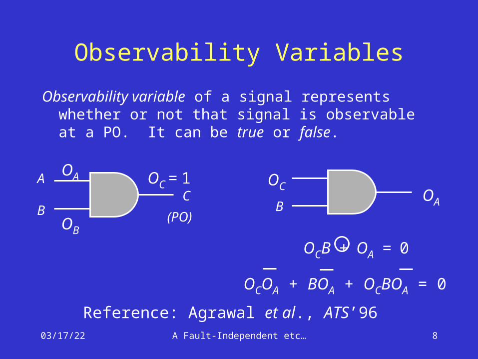
Observability Variables
Observability variable of a signal represents whether or not that signal is observable at a PO. It can be true or false.
OCOA + BOA + OCBOA = 0
OCB + OA = 0
A
BC
OB
OA OC = 1
(PO)B
OA
OC
Reference: Agrawal et al., ATS’96

04/18/23 A Fault-Independent etc… 9
Adding Observability Variables to Implication Graph
OCOA + BOA + OCBOA = 0 B
OA
OC
A B C
A B C
OC OA
OC OA
OB can be added similarly.

04/18/23 A Fault-Independent etc… 10
Transitive Closure•Transitive closure of a directed graph
contains the same set of nodes as the original graph.
•If there is a directed path from node a to b, then the transitive closure contains an edge from a to b.
ab
c d
ab
c d
A graph Transitive closure

04/18/23 A Fault-Independent etc… 11
Stuck-at Faults
• This is a type of fault, which causes a line to hold a constant logic value, irrespective of change of state at previous stages.
• There are two types of stuck-at-faults:• Stuck-at-1• Stuck-at-0
• Detection of a fault requires the fault to be activated and its effect observed at a PO.
• Fault a s-a-1 is detectable, if following conditions are simultaneously satisfied:• a = 0
• Oa = 1

04/18/23 A Fault-Independent etc… 12
Redundant Faults
•A fault that has no test is called an untestable fault.
•Any untestable fault in a combinational circuit is a redundant fault because it does not cause any change in the input/output logic function of the circuit.
•Identification of redundant faults is useful because they can be removed
• from testing consideration, or• from hardware

04/18/23 A Fault-Independent etc… 13
Redundancy Identification•ATPG based methods
• Use exhaustive test pattern generation to determine whether or not a target fault has a test.
• All redundant faults can be found, but the ATPG cost is high (exponential in circuit size).
•Fault independent methods• Analyze circuit topology and function locally
without targeting a specific fault.• Less complex than ATPG, e.g., testability
analysis.• Many (not all) redundant faults can be found
at a lower cost.

04/18/23 A Fault-Independent etc… 14
Redundancy Identification by Transitive Closure
a
b
c
d
e
s-a-0
s-a-0
Implication graph (some nodesand edges not shown)
Circuit with tworedundant faults
ImplicationPartial implicationTransitive closure edge
a b cd
OcOd

04/18/23 A Fault-Independent etc… 15
Method Summarized
• Obtain an implication graph from the circuit topology and compute transitive closure.
• There are 8 different conditions on the basis of which a fault is said to be redundant.
• Examples: • If node c implies c then s-a-0 fault on line c is
redundant.
• If node Oc implies Oc then c is unobservable and both s-a-0 and s-a-1 faults on line c are redundant.

04/18/23 A Fault-Independent etc… 16
Graph Size and Complexity
• Direct Implications: ki=1 (2ni + 2ni
2) ~ O(k)
• Partial Implications: ki=1 (ni + 2ni
2 + ni3) ~ O(k)
• Controllability nodes: • 2[ #PI + k + #PO] ~ O(k)
• Observability nodes:• 2[#PI + k + #PO + k
i=1 #fanout branches] ~ O(k)
n : number of inputs for the ith gate. k : number of gates in the given circuit.
• Time complexity for computing transitive closure is O(k3), but Gaur et al. (2002) show that empirically it has linear complexity.

04/18/23 A Fault-Independent etc… 17
Node Fixation
•Node fixation occurs when a signal implies its own complement, or vice-versa.
•Edges from all other nodes are added in the implication graph to model the unconditional fixation.
04/18/23 A Fault-Independent etc… 18
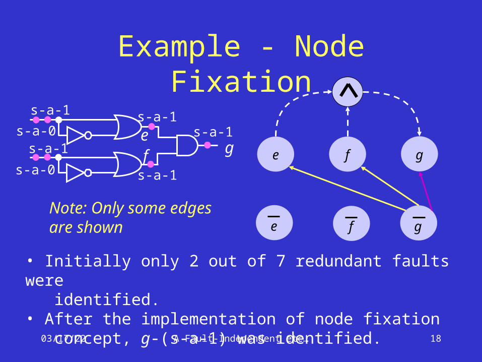
Example - Node Fixation
• Initially only 2 out of 7 redundant faults were identified.• After the implementation of node fixation concept, g-(s-a-1) was identified.
e f g
e f gNote: Only some edges are shown
s-a-1
ef g
s-a-0s-a-1
s-a-0
s-a-1
s-a-1
s-a-1

04/18/23 A Fault-Independent etc… 19
Contrapositive Rule
•If a signal p implies another signal q then q implies p (Zhao et al. VTS’97).
• This rule gives more implications in the graph after the node fixation is implemented and we are yet to verify how many more redundant faults will be found.
04/18/23 A Fault-Independent etc… 20
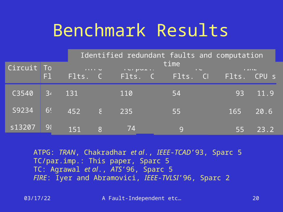
Benchmark Results
Circuit
C3540
S9234
s13207
TotalFlts.
3428
6927
9815
ATPGFlts. CPU s
131 24.6
452 803.7
151 806.5
TC/par.imp.Flts. CPU s
110 2.7
235 13.5
74 39.0
TCFlts. CPU s
54 5.9
55 9.8
9 11.2
FIREFlts. CPU s
93 11.9
165 20.6
55 23.2
Identified redundant faults and computation time
ATPG: TRAN, Chakradhar et al., IEEE-TCAD’93, Sparc 5TC/par.imp.: This paper, Sparc 5TC: Agrawal et al., ATS’96, Sparc 5FIRE: Iyer and Abramovici, IEEE-TVLSI’96, Sparc 2
04/18/23 A Fault-Independent etc… 21
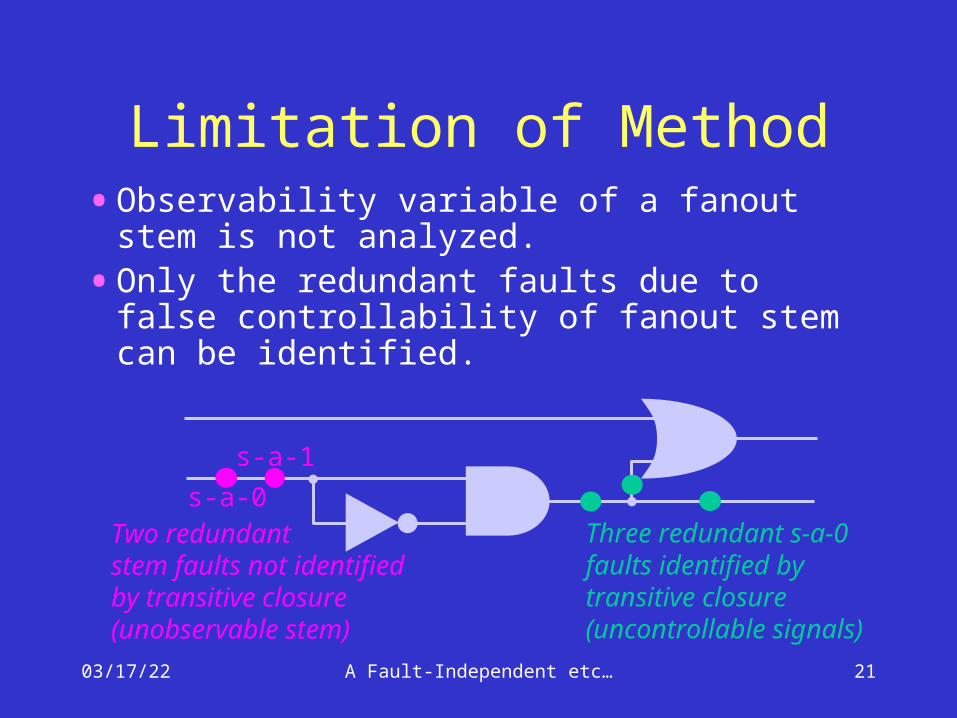
Limitation of Method•Observability variable of a fanout stem is
not analyzed.
•Only the redundant faults due to false controllability of fanout stem can be identified.
Three redundant s-a-0faults identified bytransitive closure(uncontrollable signals)
s-a-0
s-a-1
Two redundantstem faults not identifiedby transitive closure(unobservable stem)

04/18/23 A Fault-Independent etc… 22
Conclusion• Partial implications improve fault-independent
redundancy identification – present results are the best known.
• Transitive closure computation run times were linear in the number of nodes for benchmark circuits (Gaur et al., DELTA’02) -- the known worst-case complexity is O(N3) for N nodes.
• Further work has shown that many unobservable fanout stems can be identified from transitive closure analysis.

04/18/23 A Fault-Independent etc… 23
THANK YOU