Embed Size (px)
Citation preview
7/23/2019 6. Fillet Welded Joints - A Review of the Practicalities
http://slidepdf.com/reader/full/6-fillet-welded-joints-a-review-of-the-practicalities 1/6
Fillet welded joints - a review of the
practicalities
Fillet welded joints such as tee, lap and corner joints are the most common connection inwelded fabrication. In total they probably account for around 80% of all joints made by
arc welding.
It is likely that a high percentage of other joining techniques also use some form of a
fillet welded joint including nonfusion processes such as bra!ing, bra!e welding and
soldering. "he latter techniques are outside the scope of this article.
#lthough the fillet weld is so common, there are a number of aspects to be considered before producing such a weld. "his article will re$iew a number of topics that relate to
fillet welded joints and it is hoped that e$en the most seasoned fabricator or welding
person will gain from this article in some way.
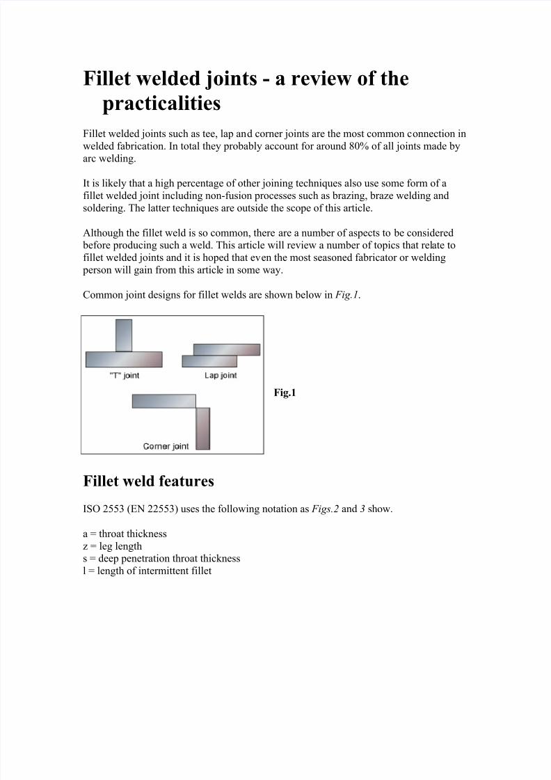
ommon joint designs for fillet welds are shown below in Fig.1.
Fig.1
Fillet weld features
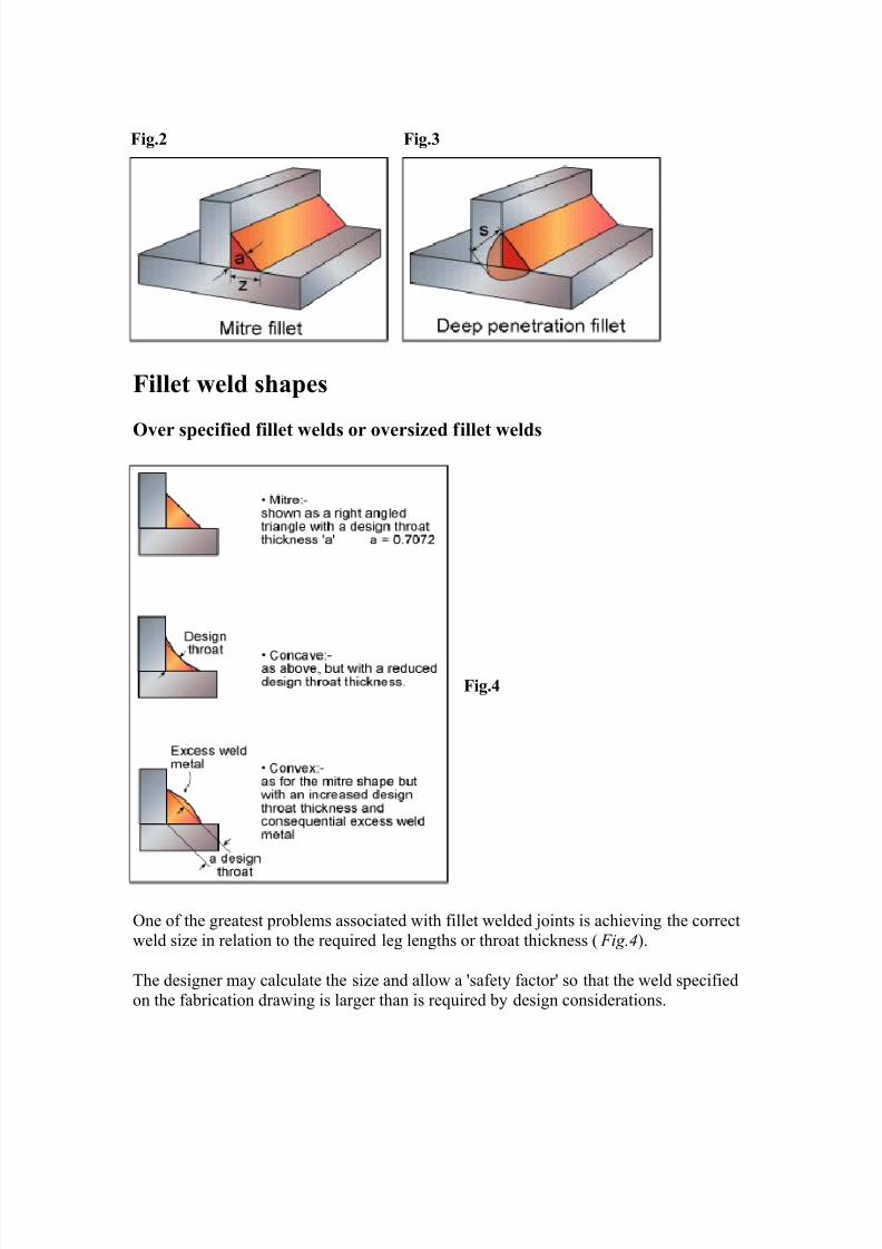
I&' ())* +- (())* uses the following notation as Figs.2 and 3 show.
a / throat thickness
! / leg lengths / deep penetration throat thickness
l / length of intermittent fillet
7/23/2019 6. Fillet Welded Joints - A Review of the Practicalities
http://slidepdf.com/reader/full/6-fillet-welded-joints-a-review-of-the-practicalities 2/6
Fig.2 Fig.3
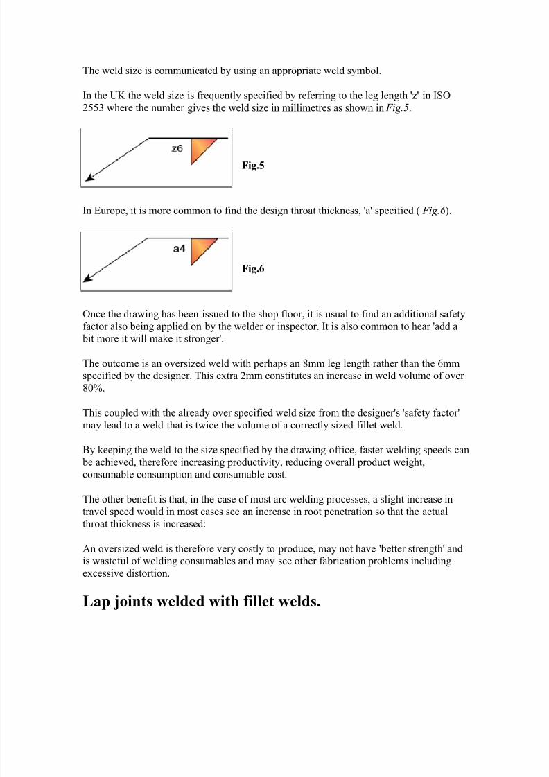
Fillet weld shapes
Over specified fillet welds or oversized fillet welds
Fig.4
'ne of the greatest problems associated with fillet welded joints is achie$ing the correct
weld si!e in relation to the required leg lengths or throat thickness + Fig.4.
"he designer may calculate the si!e and allow a safety factor so that the weld specified
on the fabrication drawing is larger than is required by design considerations.
7/23/2019 6. Fillet Welded Joints - A Review of the Practicalities
http://slidepdf.com/reader/full/6-fillet-welded-joints-a-review-of-the-practicalities 3/6
"he weld si!e is communicated by using an appropriate weld symbol.
In the 12 the weld si!e is frequently specified by referring to the leg length ! in I&'
())* where the number gi$es the weld si!e in millimetres as shown in Fig.5.
Fig.5
In urope, it is more common to find the design throat thickness, a specified + Fig.6 .
Fig.6
'nce the drawing has been issued to the shop floor, it is usual to find an additional safety
factor also being applied on by the welder or inspector. It is also common to hear add a bit more it will make it stronger.
"he outcome is an o$ersi!ed weld with perhaps an 8mm leg length rather than the 3mm
specified by the designer. "his e4tra (mm constitutes an increase in weld $olume of o$er
80%.
"his coupled with the already o$er specified weld si!e from the designers safety factormay lead to a weld that is twice the $olume of a correctly si!ed fillet weld.
5y keeping the weld to the si!e specified by the drawing office, faster welding speeds can
be achie$ed, therefore increasing producti$ity, reducing o$erall product weight,consumable consumption and consumable cost.
"he other benefit is that, in the case of most arc welding processes, a slight increase in
tra$el speed would in most cases see an increase in root penetration so that the actual
throat thickness is increased6
#n o$ersi!ed weld is therefore $ery costly to produce, may not ha$e better strength andis wasteful of welding consumables and may see other fabrication problems including
e4cessi$e distortion.
ap joints welded with fillet welds.

7/23/2019 6. Fillet Welded Joints - A Review of the Practicalities
http://slidepdf.com/reader/full/6-fillet-welded-joints-a-review-of-the-practicalities 4/6
#s discussed earlier, o$ersi!ed welds are commonplace and the lap joint is no e4ception.
"he designer may specify a leg length that is equal to the material thickness as in Fig.7 .
Fig.!
&trength considerations may mean that the fillet weld si!e need not be anywhere near the
plate thickness. In practice the weld may also be deficient in other ways for e4ample6
Fig."
7ue to melting away of the corner of the upper plate + Fig.8, the $ertical leg length is
reduced meaning that the design throat has also been reduced therefore an undersi!edweld has been created. are is therefore needed to ensure that the corner of the upper
plate is not melted away. Ideally the weld should be some 0.)9mm clear of the top
corner + Fig.9.
Fig.#
It may be the designer may therefore specify a slightly smaller leg length compared to the
thickness of the component.
"o compensate for this reduction in throat thickness it may be necessary to specify a deep
penetration fillet weld. "his amount of additional penetration would need to be confirmed
by suitable weld tests. #dditional controls may also be needed during production weldingto ensure that this additional penetration is being achie$ed consistently.
7/23/2019 6. Fillet Welded Joints - A Review of the Practicalities
http://slidepdf.com/reader/full/6-fillet-welded-joints-a-review-of-the-practicalities 5/6
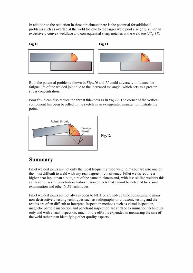
In addition to the reduction in throat thickness there is the potential for additional
problems such as o$erlap at the weld toe due to the larger weld pool si!e + Fig.10 or an
e4cessi$ely con$e4 weldface and consequential sharp notches at the weld toe + Fig.11.
Fig.1$ Fig.11
5oth the potential problems shown in Figs.10 and 11 could ad$ersely influence the
fatigue life of the welded joint due to the increased toe angle, which acts as a greaterstress concentration.
:oor fitup can also reduce the throat thickness as in Fig.12. "he corner of the $ertical
component has been be$elled in the sketch in an e4aggerated manner to illustrate the point.
Fig.12
%u&&ar'
Fillet welded joints are not only the most frequently used weld joints but are also one of
the most difficult to weld with any real degree of consistency. Fillet welds require a
higher heat input than a butt joint of the same thickness and, with less skilled welders this
can lead to lack of penetration and;or fusion defects that cannot be detected by $isuale4amination and other -7" techniques.
Fillet welded joints are not always open to -7" or are indeed time consuming to many
nondestructi$ely testing techniques such as radiography or ultrasonic testing and theresults are often difficult to interpret. Inspection methods such as $isual inspection,
magnetic particle inspection and penetrant inspection are surface e4amination techniques
only and with $isual inspection, much of the effort is e4pended in measuring the si!e of
the weld rather than identifying other quality aspects.

7/23/2019 6. Fillet Welded Joints - A Review of the Practicalities
http://slidepdf.com/reader/full/6-fillet-welded-joints-a-review-of-the-practicalities 6/6
Fillet welded joints are therefore much more difficult to weld and inspect. 'ften the
welds that are produced are larger than they need to be or they may be of a poor shape
which can ad$ersely influence their ser$ice performance.
"o o$ercome these difficulties, designers need to specify accurately the most appropriate
throat si!e and welding personnel should stri$e to achie$e the specified design si!e.<elders also need to be adequately trained and sufficiently skilled to be capable of
maintaining an acceptable weld quality.