Embed Size (px)
Citation preview
Document Number: 334400-001US
5th Generation Intel® Core™ Processor
Family with ECC (Formally Known as
Broadwell) for Mobile Platform - Lava
Canyon 2 Customer Reference Board
(CRB)
User Guide
May 2016

5th Generation Intel® Core™ Processor Family with ECC
for Mobile Platform – Lava Canyon 2 CRB
User Guide May 2016
2 Document Number: 334400-001US
You may not use or facilitate the use of this document in connection with any infringement or other legal analysis concerning Intel products
described herein. You agree to grant Intel a non-exclusive, royalty-free license to any patent claim thereafter drafted which includes subject matter
disclosed herein
No license (express or implied, by estoppel or otherwise) to any intellectual property rights is granted by this document.
All information provided here is subject to change without notice. Contact your Intel representative to obtain the latest Intel product specifications
and roadmaps.
This document contains information on products in the design phase of development.
The products described may contain design defects or errors known as errata which may cause the product to deviate from published
specifications. Current characterized errata are available on request.
Copies of documents which have an order number and are referenced in this document may be obtained by calling 1-800-548-4725 or by visiting:
http://www.intel.com/design/literature.htm
Intel and the Intel logo are trademarks of Intel Corporation in the U.S. and/or other countries.
*Other names and brands may be claimed as the property of others.
Copyright © 2016, Intel Corporation. All rights reserved.

5th Generation Intel® Core™ Processor Family with ECC
for Mobile Platform – Lava Canyon 2 CRB
May 2016 User Guide
Document Number: 334400-001US 3
Contents
1.0 Introduction ............................................................................................................................................ 5
1.1 Terminology ...................................................................................................................................................... 5
1.2 Reference Documents ................................................................................................................................ 6
2.0 Broadwell Platform CRB Features .............................................................................................. 7
2.1 Lava Canyon 2 CRB Feature Set Summary ................................................................................ 8
2.2 Power Supply Solutions, Usage, and Recommendations ................................................... 9
3.0 Reference Board Summary ......................................................................................................... 11
3.1 Features ............................................................................................................................................................ 11
3.2 Connectors, Headers, and Jumpers ............................................................................................... 13
3.2.1 Back Panel Connectors ........................................................................................................ 14 3.2.2 Front Panel Header ................................................................................................................. 14 3.2.3 CPU Straps ................................................................................................................................... 16 3.2.4 Configuration Jumpers/Switches .................................................................................. 16
3.3 LEDs ..................................................................................................................................................................... 17
4.0 Quick Start Guide .............................................................................................................................. 18
4.1 Required Peripherals ................................................................................................................................ 18
4.2 Instructions to Flash BIOS to SPI ................................................................................................... 18
4.3 Operate, Power Up, and Power Down the Reference Board ......................................... 19
Figures Figure 1. CRB Block Diagram ...................................................................................................................................... 7 Figure 2 Pin Out Specification ................................................................................................................................ 10 Figure 3. CRB Top View ................................................................................................................................................ 11 Figure 4. CRB Bottom View ....................................................................................................................................... 12 Figure 5. CRB Back Connectors .............................................................................................................................. 14 Figure 6. Front Panel Header Pin Out Diagram ............................................................................................ 15
Tables Table 1. Terminology ...................................................................................................................................................... 5 Table 2. Reference Documents ................................................................................................................................ 6 Table 3. CRB Feature Set Summary ..................................................................................................................... 8 Table 4. CRB Components List .............................................................................................................................. 13 Table 5. Back Panel Components List............................................................................................................... 14 Table 6. Front Panel Header Pin Out Description ..................................................................................... 15 Table 7. CPU Straps ...................................................................................................................................................... 16 Table 8. Configuration Jumper/Switches ....................................................................................................... 17 Table 9. CRB LEDs ......................................................................................................................................................... 17
5th Generation Intel® Core™ Processor Family with ECC
for Mobile Platform – Lava Canyon 2 CRB
User Guide May 2016
4 Document Number: 334400-001US
Revision History
Date Revision Description
May 2016 001 Initial release.
§

Introduction
5th Generation Intel® Core™ Processor Family with ECC
for Mobile Platform – Lava Canyon 2 CRB
May 2016 User Guide
Document Number: 334400-001US 5
1.0 Introduction
This User Guide describes the typical hardware set-up procedures,
features, and use of the Lava Canyon 2 Customer Reference Board (CRB)
for the 5th Generation Intel® Core™ Processor Family with ECC (Formally
Known as Broadwell) for Mobile Platform - Lava Canyon 2 Customer
Reference Board (CRB). This document should be read in its entirety
prior to powering ON the CRB.
The Quick Start section provides quick start procedures for reference. It
is recommended to have both the schematic and CRB present as you
proceed through this document.
The Lava Canyon 2 CRB is a dual channel DDR3L mobility platform. It’s
designed to support the Broadwell-H processor Ball Grid Array (BGA)
and the Intel® 8 Series Chipset family (Lynx* Point) chipset.
This document is relevant to the Lava Canyon 2 CRB only. The
references in this document correlate to reference designators and
board properties of the Lava Canyon 2 CRB. Socket and connector
locations are labeled with a letter-number combination (for example, the
first memory SODIMM connector is located at J7G1). Refer to the
silkscreen labeling on the CRB for socket locations.
The Intel® 8 Series Chipset family, formerly known as Lynx*
Point/Haswell Platform Hub Controller (PCH) and Haswell Platform was
formerly known as Shark Bay Platform.
1.1 Terminology
Table 1. Terminology
Term Description
BGA Ball Grid Array
CRB Customer Reference Board
DDI Digital Display Interface
DMI Direct Media Interface
eDP Embedded Display Port

Introduction
5th Generation Intel® Core™ Processor Family with ECC
for Mobile Platform – Lava Canyon 2 CRB
User Guide May 2016
6 Document Number: 334400-001US
Term Description
FCIM Full Clock Integration Mode
LAN Local Area Network
LED Light Emitting Diode
PCH Platform Hub Controller
PCI Peripheral Control Interface
PCIe* PCI Express*
RTC Real Time Clock
SATA Serial AT Attachment
SIO Super Input/Output
U-DIMM Unbuffered Dual In-line Memory Module
USB Universal Serial Bus
VGA Video Graphics Array
XDP Extended Debut Port
1.2 Reference Documents
Table 2. Reference Documents
Document Document No./Location
Mobile 5th Generation Intel® Core™ Processor Family Supporting 5th Generation Intel® Core™ Processor based on Mobile H-Processor Line – External Design Specification (EDS) Volume 1 of 2
558039
5th Generation Intel® Core™ Processor Family, Intel® Core™ M Processor Family, Mobile Intel® Pentium® Processor Family, Mobile Intel® Celeron® Processor Family, and Intel® Xeon® Processor E3-1200 v4 Product Family External Design Specification (EDS) – Volume 2 of 2
514525
Intel® 8 Series / C220 Series Chipset Family Platform Controller Hub (PCH) –
External Design Specification (EDS) 486708
Lava Canyon 2 –Schematic 559329
Lava Canyon 2 – Customer Reference Board File 559326
Lava Canyon 2 Platform - Bill of Materials (BOM) 559328
Broadwell Platforms Reference Validation Platform BIOS v119.1 for Lava
Canyon 2 CRB Release Notes - BIOS 558421
§
Broadwell Platform CRB Features
5th Generation Intel® Core™ Processor Family with ECC
for Mobile Platform – Lava Canyon 2 CRB
May 2016 User Guide
Document Number: 334400-001US 7
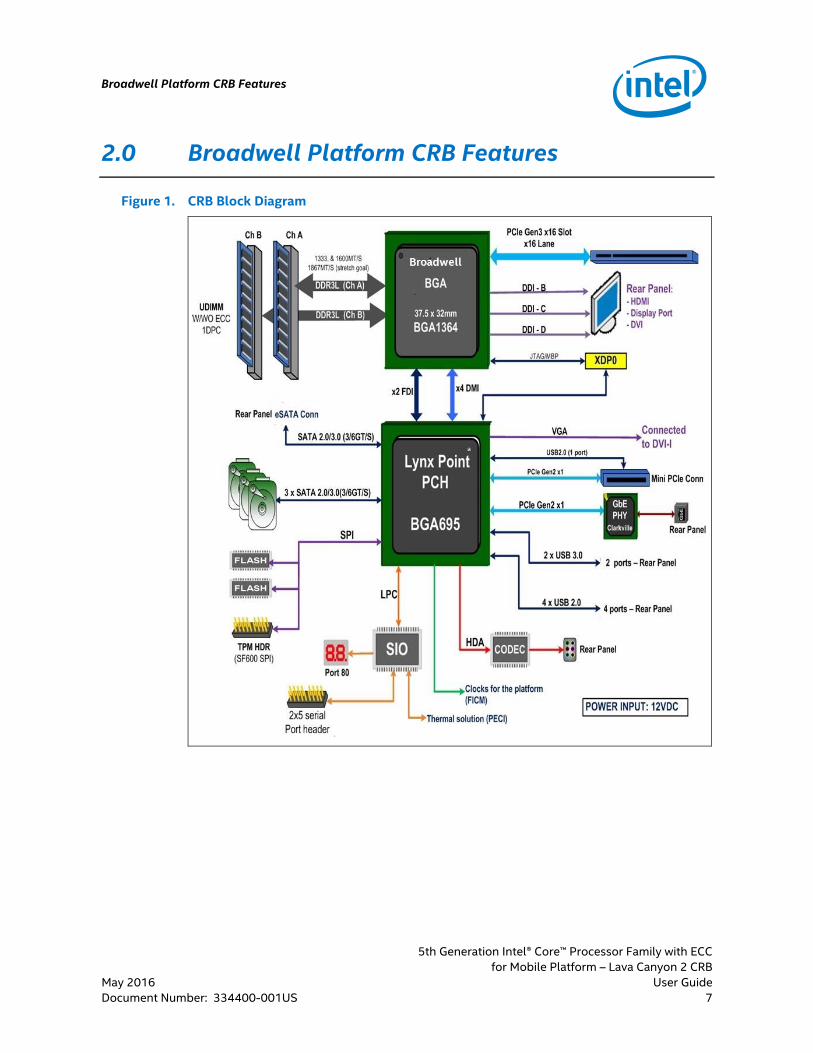
2.0 Broadwell Platform CRB Features
Figure 1. CRB Block Diagram

Broadwell Platform CRB Features
5th Generation Intel® Core™ Processor Family with ECC
for Mobile Platform – Lava Canyon 2 CRB
User Guide May 2016
8 Document Number: 334400-001US
2.1 Lava Canyon 2 CRB Feature Set Summary
Table 3. CRB Feature Set Summary
CRB Implementation Comments
Processor
Broadwell-Mobile processor supported in BGA Package
Supports 2 DDR3L channels
Supports x4 (in each direction) Direct Media
Interface (DMI) interface (lane reversed)
Supports x2 FDI interface (lane reversed)
1364-pin BGA Foot-Print
Chipset Lynx* Point - H 695-pin BGA Foot-Print
Memory 2x DDR3L ECC Unbuffered Dual In-line Memory Module (U-DIMM) slots
Lava Canyon 2 supports:
DDR3L frequency of up to 1600 MT/s
J7G1 (Channel A)
J7G2 (Channel B)
PCIe*/ External Graphics
1x PCI Express* 3.0 x16
Can be supported as:
1x16 PEG through x16 slot on CRB
Video Display Port
Digital Display Interface (DDI) Port B
Back panel Display Port connector
Video High Definition Multimedia Interface (HDMI)
DDI Port C
Back panel HDMI connector
Video Digital Video Interface (DVI)
DDI Port D
Back panel DVI connector
Video Video Graphics Array (VGA)
Supports Video Graphics Array (VGA) through
Dongle
On-Board LAN Ethernet
10/100/1000 Mbps Ethernet through the onboard
(Clarkville) PHY
On board RJ45 interface
BIOS (SPI)
SPI flash devices
Support for Serial Flash Discovery parameter
(SFDP)
Supports TPM
2x 8 MB SPI Flash device parts provided on board
Support new Dual I/O Fast read, Quad I/O Fast
read, Quad Output Fast read
TPM TPM on SPI Interface 20-pin header
SATA Up to 5x Serial AT Attachment (SATA) Ports
All 5 ports capable of 6GT/s
3 Cable Connector
1 to Mini PCIe *
1 eSATA
Broadwell Platform CRB Features
5th Generation Intel® Core™ Processor Family with ECC
for Mobile Platform – Lava Canyon 2 CRB
May 2016 User Guide
Document Number: 334400-001US 9
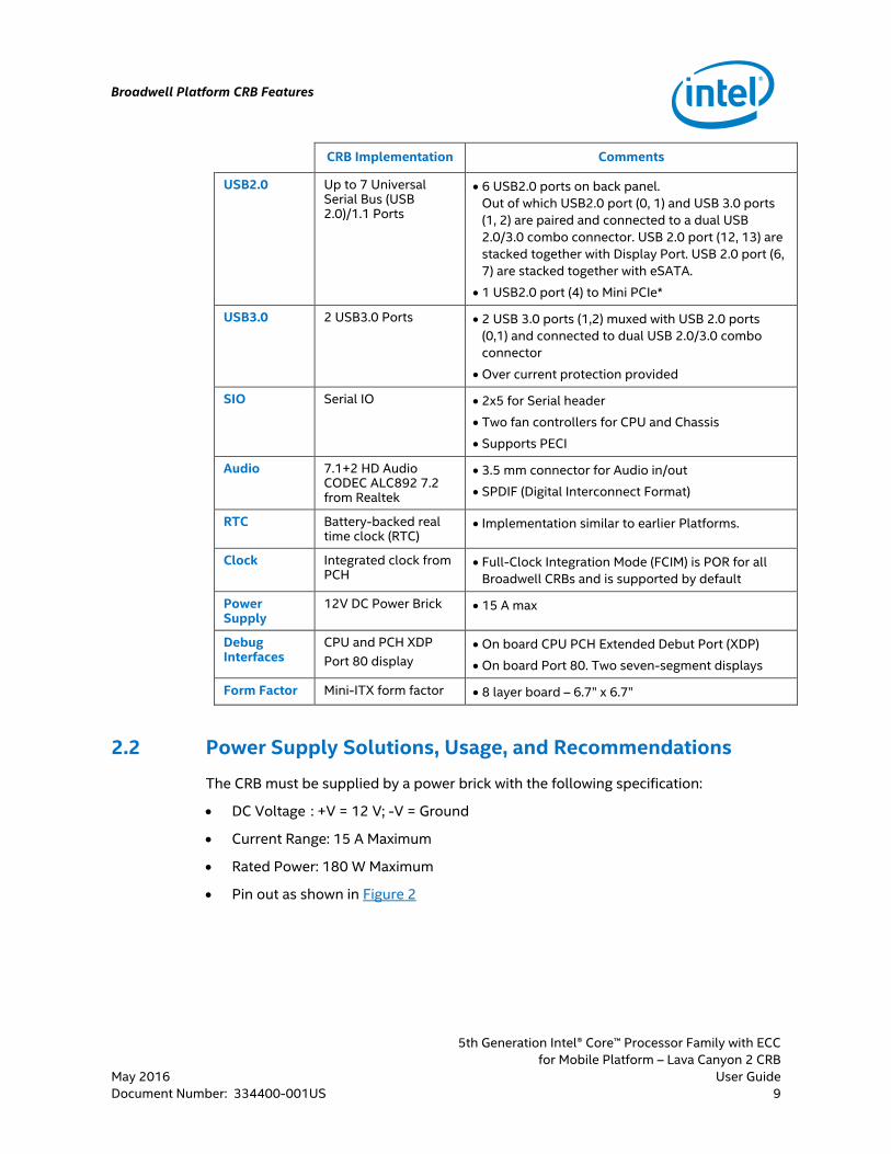
CRB Implementation Comments
USB2.0 Up to 7 Universal Serial Bus (USB 2.0)/1.1 Ports
6 USB2.0 ports on back panel.
Out of which USB2.0 port (0, 1) and USB 3.0 ports
(1, 2) are paired and connected to a dual USB
2.0/3.0 combo connector. USB 2.0 port (12, 13) are
stacked together with Display Port. USB 2.0 port (6,
7) are stacked together with eSATA.
1 USB2.0 port (4) to Mini PCIe*
USB3.0 2 USB3.0 Ports 2 USB 3.0 ports (1,2) muxed with USB 2.0 ports
(0,1) and connected to dual USB 2.0/3.0 combo
connector
Over current protection provided
SIO Serial IO 2x5 for Serial header
Two fan controllers for CPU and Chassis
Supports PECI
Audio 7.1+2 HD Audio CODEC ALC892 7.2 from Realtek
3.5 mm connector for Audio in/out
SPDIF (Digital Interconnect Format)
RTC Battery-backed real time clock (RTC)
Implementation similar to earlier Platforms.
Clock Integrated clock from PCH
Full-Clock Integration Mode (FCIM) is POR for all
Broadwell CRBs and is supported by default
Power Supply
12V DC Power Brick 15 A max
Debug Interfaces
CPU and PCH XDP
Port 80 display
On board CPU PCH Extended Debut Port (XDP)
On board Port 80. Two seven-segment displays
Form Factor Mini-ITX form factor 8 layer board – 6.7” x 6.7”
2.2 Power Supply Solutions, Usage, and Recommendations
The CRB must be supplied by a power brick with the following specification:
DC Voltage : +V = 12 V; -V = Ground
Current Range: 15 A Maximum
Rated Power: 180 W Maximum
Pin out as shown in Figure 2

Broadwell Platform CRB Features
5th Generation Intel® Core™ Processor Family with ECC
for Mobile Platform – Lava Canyon 2 CRB
User Guide May 2016
10 Document Number: 334400-001US
Figure 2 Pin Out Specification
Caution: Intel recommends using a power brick that matches the power and Pin Out specification. Using the wrong power type or pin type may damage the board permanently. For example, Mean Well GS220A12-R7B matches the requirement for the power supply.
§
Reference Board Summary
5th Generation Intel® Core™ Processor Family with ECC
for Mobile Platform – Lava Canyon 2 CRB
May 2016 User Guide
Document Number: 334400-001US 11
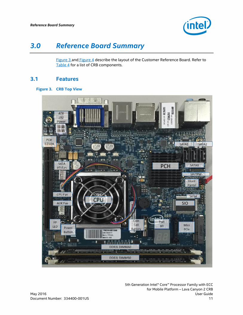
3.0 Reference Board Summary
Figure 3 and Figure 4 describe the layout of the Customer Reference Board. Refer to
Table 4 for a list of CRB components.
3.1 Features
Figure 3. CRB Top View
Reference Board Summary
5th Generation Intel® Core™ Processor Family with ECC
for Mobile Platform – Lava Canyon 2 CRB
User Guide May 2016
12 Document Number: 334400-001US
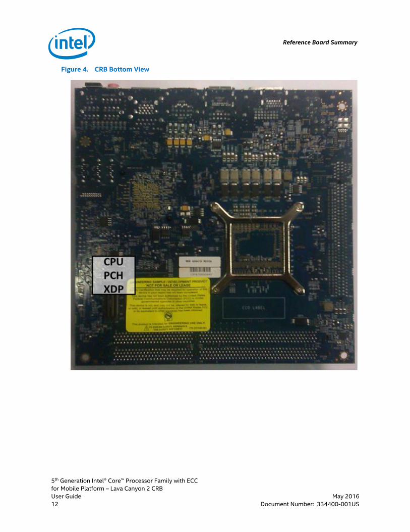
Figure 4. CRB Bottom View

Reference Board Summary
5th Generation Intel® Core™ Processor Family with ECC
for Mobile Platform – Lava Canyon 2 CRB
May 2016 User Guide
Document Number: 334400-001US 13
Table 4. CRB Components List
Item# Description Reference
1 CPU U3E1
2 CPU PCH XDP J1T1
3 CPU Fan Connector J1D1
4 DDR3L DIMM A0 J7G1
5 DDR3L DIMM B0 J7G2
6 PCH U6C1
7 SATA0 Connector J7C1
8 SATA1 Connector J7C2
9 SATA2 Connector J7C3
10 SATA HD Power J1C1
11 PCIe* 3.0 x16 Connector J1B1
12 Mini PCIe* Connector J7F1
13 Serial Port J7E1
14 Speaker LS5E1
15 Front Panel Header J7D1
16 Front Panel Light Emitting Diode (LED) Header J1E2
17 Power Button Header J1E3
18 Port 80 Display DS5F1
19 Coin cell battery holder BT5F1
20 Super Input/Output (SIO) NCT6776F U7E1
21 SPI Based TPM Header J7C4
22 AUX Fan Header J1E1
24 ATX 2x2 Power Connector J1A1
3.2 Connectors, Headers, and Jumpers
This section describes the board’s various connectors, headers, and jumpers.

Reference Board Summary
5th Generation Intel® Core™ Processor Family with ECC
for Mobile Platform – Lava Canyon 2 CRB
User Guide May 2016
14 Document Number: 334400-001US
Caution: Many of the connectors provide an operating voltage (+5 V DC and +12 V DC, for example) to devices inside the computer chassis, such as fans and internal peripherals. Most of these connectors are not over-current protected. Do not use these connectors for powering devices external to the computer chassis. A fault in the load presented by the external devices could cause damage to the computer, the interconnecting cable, and the external devices themselves.
3.2.1 Back Panel Connectors
Figure 5 shows the back panel connectors on the board.
Figure 5. CRB Back Connectors
Table 5. Back Panel Components List
Item# Description Reference
1 HDMI connector J2A1
2 DVI Connector J3A1
3 Display Port with dual USB2.0 Connector J4A1
4 eSATA Port with dual USB2.0 Connector J5A1
5 Dual USB 3.0 with RJ45 Connector J6A1
6 Five port Audio Jack and SPDIF J7A1
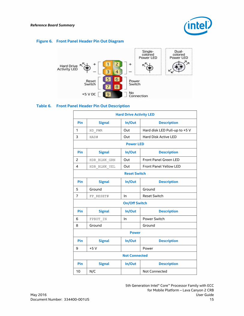
3.2.2 Front Panel Header
The CRB has a front panel header comprising of the pin out for the Power Switch, Reset
Switch, Hard Drive Activity LED, Power LED and +5V DC. Figure 6 shows the pin out for
the header. Refer to Figure 6 for location of the Front Panel Header, J7D1, on the CRB
board.
Reference Board Summary
5th Generation Intel® Core™ Processor Family with ECC
for Mobile Platform – Lava Canyon 2 CRB
May 2016 User Guide
Document Number: 334400-001US 15
Figure 6. Front Panel Header Pin Out Diagram
Table 6. Front Panel Header Pin Out Description
Hard Drive Activity LED
Pin Signal In/Out Description
1 HD_PWR Out Hard disk LED Pull-up to +5 V
3 HAD# Out Hard Disk Active LED
Power LED
Pin Signal In/Out Description
2 HDR_BLNK_GRN Out Front Panel Green LED
4 HDR_BLNK_YEL Out Front Panel Yellow LED
Reset Switch
Pin Signal In/Out Description
5 Ground Ground
7 FP_RESET# In Reset Switch
On/Off Switch
Pin Signal In/Out Description
6 FPBUT_IN In Power Switch
8 Ground Ground
Power
Pin Signal In/Out Description
9 +5 V Power
Not Connected
Pin Signal In/Out Description
10 N/C Not Connected
Reference Board Summary
5th Generation Intel® Core™ Processor Family with ECC
for Mobile Platform – Lava Canyon 2 CRB
User Guide May 2016
16 Document Number: 334400-001US
The Power Switch is also alternatively accessible from header J1E3. A
button/switch needs to be connected to these pins.
The Power LED can use either a Single-colored or a Dual-colored Power LED. The
header is also alternatively accessible from header J1E2.
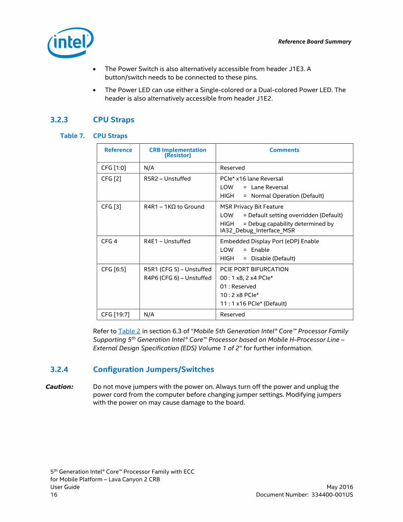
3.2.3 CPU Straps
Table 7. CPU Straps
Reference CRB Implementation (Resistor)
Comments
CFG [1:0] N/A Reserved
CFG [2] R5R2 – Unstuffed PCIe* x16 lane Reversal
LOW = Lane Reversal
HIGH = Normal Operation (Default)
CFG [3] R4R1 – 1KΩ to Ground MSR Privacy Bit Feature
LOW = Default setting overridden (Default)
HIGH = Debug capability determined by IA32_Debug_Interface_MSR
CFG 4 R4E1 – Unstuffed Embedded Display Port (eDP) Enable
LOW = Enable
HIGH = Disable (Default)
CFG [6:5] R5R1 (CFG 5) – Unstuffed
R4P6 (CFG 6) – Unstuffed
PCIE PORT BIFURCATION
00 : 1 x8, 2 x4 PCIe*
01 : Reserved
10 : 2 x8 PCIe*
11 : 1 x16 PCIe* (Default)
CFG [19:7] N/A Reserved
Refer to Table 2 in section 6.3 of “Mobile 5th Generation Intel® Core™ Processor Family
Supporting 5th Generation Intel® Core™ Processor based on Mobile H-Processor Line –
External Design Specification (EDS) Volume 1 of 2” for further information.
3.2.4 Configuration Jumpers/Switches
Caution: Do not move jumpers with the power on. Always turn off the power and unplug the power cord from the computer before changing jumper settings. Modifying jumpers with the power on may cause damage to the board.

Reference Board Summary
5th Generation Intel® Core™ Processor Family with ECC
for Mobile Platform – Lava Canyon 2 CRB
May 2016 User Guide
Document Number: 334400-001US 17
Table 8. Configuration Jumper/Switches
Reference Comments
J6B1
Flash Descriptor Security Override
(1-2) : Enable Security
Open : Disable (Default) 1 Refer to HDA_SDO strap of Intel 8 Series PCH EDS
(Section 2.18)
J6D1
RTC Reset
(1-2) : Clear PCH RTC
Open : Normal (Default) 1 Refer to RTCRST# strap of Intel 8 Series PCH EDS
(section 2.27)
J6D2
SRTC Reset
(1-2) : Clear ME RTC
Open : Normal (Default) 1 Refer to SRTCRST# strap of Intel 8 Series PCH EDS
(section 2.27)
J7D2
BIOS Recovery
(1-2) : Recover Mode
Open : Normal (Default) 1 GPIO22 of Intel 8 Series PCH
Note: 1 Refer to Table 2 “Intel 8 Series/C220 Series Chipset Family Platform Controller Hub
(PCH) – External Design Specification (EDS)” for more information.
3.3 LEDs
The following LEDs provide status of various functions:
Table 9. CRB LEDs
Reference Function
DS4C1 VCC3P3_A (Yellow LED)
DS4C2 CATERR - Indicates CATASTROPHIC ERROR (Red LED)
DS6E1, DS6E2, DS6E3
Mini-PCIE* Local Area Network (LAN) Status (Green LED)
§

Quick Start Guide
5th Generation Intel® Core™ Processor Family with ECC
for Mobile Platform – Lava Canyon 2 CRB
User Guide May 2016
18 Document Number: 334400-001US
4.0 Quick Start Guide
The following sections summarize the necessary hardware and power-on instructions
for the customer reference board.
4.1 Required Peripherals
Fan/Heat sink combination for processor
DDR3L SDRAM ECC U-DIMM
Mobile 12V DC Power Brick
Keyboard, Mouse
SATA Hard Drive
SATA cable
PCI Express* Graphics Card if not using Internal Graphics
External display
4.2 Instructions to Flash BIOS to SPI
The following is setup information to Flash the BIOS to the SPI:
The Flash BIOS can be programmed in dual I/O mode as well as quad I/O mode for
more speed.
In-Circuit programming of SPI flash is supported only when the system power is
OFF.
The Dediprog SF600* with Adaptor B is connected to the header at J7C4. Refer to
Table 6 for location of the header.
Figure 7. Dediprog SF600* with Adaptor B
1. Install the latest USB drivers for the Dediprog SF600* Programmer on the host
platform.

Quick Start Guide
5th Generation Intel® Core™ Processor Family with ECC
for Mobile Platform – Lava Canyon 2 CRB
May 2016 User Guide
Document Number: 334400-001US 19
2. Ensure the target board that needs to be programmed is in the S5 State by
connecting power to board.
If the target board is in the S5 State the VCC3P3_A (DS4C1) LED will be
illuminated.
3. Launch the Dediprog* tool and confirm the settings in the menus located at Config
Miscellaneous Settings Dual/Quad IO Option select Always Single I/O default
setting is “Single I/O”.
4. Ensure that “Currently working on” is in the “Application Memory Chip 1”.
5. Go to “File” and select the .bin file to program chip1.
6. Execute the batch operation to erase and program the chip.
Note: Ensure Quad IO/Single IO is set when the programming begins.
7. On seeing “no operation on-going” at the bottom left, switch to “Application
Memory chip 2”.
8. Select the .bin file for chip2 and execute the batch operation.
4.3 Operate, Power Up, and Power Down the Reference Board
Note: See Table 4 for a list of all component locations.
Complete the following procedures to operate the reference board.
1. Place one or more DDR3L SO-DIMMs in memory sockets, populating J7G1 and/or
J7G2.
2. Attach the heat sink/fan for the processor at U3E1 and plug the fan power cable
into J1D1.
3. Install the configuration jumpers as shown in Table 8, “Configuration
Jumper/Switches”.
4. Verify presence of RTC battery in Battery Holder at BT5F1.
Note: The following steps must be completed by the user:
1. Plug a Power Brick into the chassis.
Alternatively, if a chassis is not used, connect the power brick to the board’s ATX
2x2 Power Connector (J1A1) using a power cable.
2. Attach a hard drive at J7C1, J7C2, and/or J7C3.
3. Connect a USB keyboard in one of the USB connectors.
4. Connect a USB mouse in one of the USB connectors.
5. (Only if chassis is not used) If internal graphics is not used, plug a PCI Express*
Graphics card in the PCI-E x16 slot, J1B1, and connect a monitor to the card.
Quick Start Guide
5th Generation Intel® Core™ Processor Family with ECC
for Mobile Platform – Lava Canyon 2 CRB
User Guide May 2016
20 Document Number: 334400-001US
Powering up the board:
1. Press the Front Panel power button that is connected to either J7D1 or J1E3.
2. As the system boots, press F2 to enter the BIOS setup screen.
3. Check time, date, and configuration settings. The default settings should be
sufficient for most users.
4. The PCIe* hot plug support has to be enabled in the setup if hot plug detection is
required.
5. Save and exit the BIOS setup and the system boots and is ready for use.
Powering down the board:
Below are three options for powering-down the Lava Canyon 2 CRB:
Use OS-controlled shutdown through the Windows* Start menu (or equivalent)
Press the Front Panel power button connected to the motherboard at J7D1 or
J1E3 to begin power-down.
If the system is hung up or stalled, it is possible to asynchronously shut the system
down by holding the power button down continuously for four-seconds.
Caution: Intel does not recommend powering down the board by simply shutting off power at the power supply. Sudden power-off might cause the damage to components on the CRB while it is still in operation mode.
§