Embed Size (px)
Citation preview

5G Technologies, Standards and Commercialization
Liangping Ma
August 1, 2018
© 2018 InterDigital, Inc. All rights reserved. 1

2
Who is InterDigital? Invention, Collaboration, Contribution
© 2018 InterDigital, Inc. All rights reserved.
Berlin
Montreal, QC (R&D)
London (R&D)
Seoul
Buffalo, NYMelville, NY (R&D)
Conshohocken, PA (R&D)Wilmington, DE (HQ)San Diego, CA (R&D)
• Four decades of discovery and innovation in wireless
• Pioneer in digital wireless technologies
• Key contributions to global wireless standards
• Inventing solutions for more efficient broadband networks
• ~190 engineers (~80% of whom hold advanced degrees)

3
What is 5G?
© 2018 InterDigital, Inc. All rights reserved.

4
5G Use Cases and Key Requirements
Enhanced Mobile Broadband (eMBB)▪ Peak data rates: 20 Gbps (DL) and 10 Gbps (UL)
▪ Peak spectral efficiency: 30 bps/Hz (DL) and 15 bps/Hz (UL)
▪ 4 ms user plane latency
▪ Indoor/hotspot and enhanced wide-area coverage
Massive Machine Type Communications (mMTC)▪ Low data rates
(1 to 100 kbps)
▪ High device density(up to 1,000,000 /km2)
▪ Latency: Seconds to hours
▪ Low power: Up to 15 years battery life
Ultra-Reliable and Low Latency Communications (URLLC)
▪ Low to medium data rates (50 kbps to 10 Mbps)
▪ 0.5 ms user plane latency
▪ 99.999% reliability and availability within 1 ms
▪ High mobility
Key challenge for 5G design: support for different services having diverging requirements
Source: ITU-R SG5 WP-5D
© 2018 InterDigital, Inc. All rights reserved.

5
What Differentiates 5G from Previous Generations?
Uses Cases & Services
Voice + SMSVoice +
Small DataMobile
Broadband
Enhanced Mobile Broadband
Massive Machine Type Communications
Ultra Reliable and Low Latency Communications
Spectrum200 KHz
Channels Below 2 GHz
5 MHz Channels
Below 3.6 GHz
Up to 20 MHz Channels
Below 3.8 GHz
Up to 1 GHz Channels Below 100 GHz
Radio Technology
GSM/GPRS(Single RAT )
UMTS/HSPA(Single RAT)
LTE/LTE-A(Single RAT)
Multiple Radio Access Technologies Integrated in a 5G Network:
5G New Radio, LTE Advanced Pro, NB-IoT, Wi-Fi, …
Network Topology
Macro CellsMacro and Small Cells
Heterogeneous Macro and Small Cells
Challenging Traditional Cell and Network Concepts:
Small Cells, Mobile Edge Computing, Network Slicing, …
2G 4G 5G3G
© 2018 InterDigital, Inc. All rights reserved.
2021
6
5G 3GPP Standardization Timeline
2017 2018 2019 2020
Rel-17 Work Items
LTE Release 17LTE Release 15R14
NR SI
Full NR RAN stand-alone and CT Specifications
approved
Rel-16 specification approved with some
additional enhancements
NR R15 first drop specification completed
(NR non-standalone and CN standalone)
Phased approach enables early commercial deployment of Phase 1 in 2019 and Phase 2 in 2022+
IMT-2020 Proposal Submission
NR Rel-15
5G LTE + NB-IoT(required for
mMTC use cases for IMT-2020)
5G New Radio (NR)…
Allows for very early commercial implementation – No more hardware changes envisioned for R-15
Rel-16 SIs (RAN/SA)
Rel-17 Study Items
LTE Release 16
Additional Rel-16 SIs approved
Rel-16 Work Items (R16)
3rd drop
© 2018 InterDigital, Inc. All rights reserved.

Focus on completion of the protocol design▪ NAS protocol between the UE and the CN▪ Internal Core Network interfaces based on the
service based architecture (SBA)▪ Interconnection of the Core Network with
external networks
First set of NR specifications completed
▪ Ready for Hardware Implementation and for first phase of deployment - Non-Standalone NR only (i.e. connected and controlled by LTE)
▪ RAN1 PHY and RAN2 User Plane completed for stand-alone NR
▪ Support for Enhanced Mobile Broadband use cases only and low latency
7
5G New Radio Status – Rel-15
Core Network
and Non Access
Stratum
Radio Access
Network
Next Gen Core(NGC) architecture completed
▪ New fully flexible architecture based on Network Slicing concept and further separation of control and user planes
▪ Key functions: Session Management, Mobility Management, QoS and access agnostic CN
Focus on completion stand-alone NR
▪ Support for stand-alone NR connected directly to a 5G CN (RAN2/RAN3/RAN4)
▪ Add/complete additional enhancements to support ultra-reliable and low latency use cases (URLLC) (RAN1/RAN2)
December 2017 June 2018
© 2018 InterDigital, Inc. All rights reserved.

8
5G Design Principles
© 2018 InterDigital, Inc. All rights reserved.

9
5G NR Design Principles
Architecture & Network
• Flexible, modular and scalable architecture
• Support high level of programmability and automation in network
• Built in support of network customization via slicing
• Easy integration of new services
5G is designed to be flexible and adaptable to meet wide range of current and future requirements
Radio Access Network
• Minimize always-on signaling
• Flexible frame structure and numerology
• Support wide range of frequency bands
• Built-in support for beamforming
• Easy integration of future features
© 2018 InterDigital, Inc. All rights reserved.

10
5G Technologies
© 2018 InterDigital, Inc. All rights reserved.

11
5G RAN
LTE/4GNetwork
5G Network
LTE Base Station
New Radio RAN
InternetNon
Standalone (NSA) 5G 5G
New Radio
4G EPC
5G Core Network
Slice #3 (URLLC)
Slice #2 (IoT)
Slice #1 (eMBB)
SGW
MME
PGW
HSS
AMF
Non-Standalone (NSA) 5G enables large-scale trials and deployments starting in 2019
3GPP 5G Deployment Scenarios
3 Main Deployment Scenarios▪ NSA deployment - utilizes
LTE radio and 4G EPC as an anchor and NR Radio as hotspot▪ Allows earlier
implementability▪ Stand-alone NR – 5G RAN
connecting to 5G CN only▪ LTE radio connected to 5G
CN network
5G CN designed to interwork with the current EPC network to enable seamless migration for the operators
© 2018 InterDigital, Inc. All rights reserved.

12
Architecture options and specification timelines
© 2018 InterDigital, Inc. All rights reserved.
EPCNextGen
Core
LTE NR
3
Non-standalone Drop 1: Dec. 2017
NR
2
LTE
5
NextGenCore
NextGenCore
Standalone NRDrop 2: June 2018
EPCNextGen
Core
LTE NR
4
EPCNextGen
Core
LTE NR
7
LTE connected to 5G CNDrop 3: Dec 2018 – NR +

Control and User Plane Separation
13© 2018 InterDigital, Inc. All rights reserved.
Control and User plane separation modularizes the 5G Core Network Design
▪ Reduces Latency on application service
▪ By relocating UPFs which are closer to the RAN;
▪ Or by selecting UPFs more appropriate for the intended UE usage type without increasing the number of control plane nodes
▪ Supports increase of Data Traffic, by enabling to add user plane nodes without changing the number of CP resources in the network
▪ Independent evolution of the CP and UP functions
▪ Enables SDN routing to deliver user plane data more efficiently
5G Core Network Architecture

Service Based Architecture (SBA)
14
▪ 5G CN has been revolutionized with Service Based interfaces for core network interactions
▪ CN interfaces have traditionally been Point-to-Point (P2P) e.g. MAP, Diameter
▪ Network Functions (NFs) in 5G CN offer their services to other NFs via APIs based on web-based technology (e.g. HTTP).
▪ Makes deployment easy as libraries, development tools, and other components are broadly available.
▪ Flexible deployments of new services: possible to connect to other components without new specific interfaces
▪ Network Repository Function (NRF) allows NFs to discover the services of other NFs.
© 2018 InterDigital, Inc. All rights reserved.
SBA shifts the paradigm from telecom-style protocol interfaces to web-based APIs
UDMNSSF PCFNRF
AUSF
AF
SMFAMF
5G CN Service Based Control Plane

Network Slicing
Network Slice• Logical end-to-end network• Tailored based on service it offers (e.g.eMBB, IoT, URLCCC etc.)
Slicing offers customized network resources for different verticals
© 2018 InterDigital, Inc. All rights reserved. 15
Benefits of slicing• Flexible and modular network deployment• Isolation between dedicated network resources• New products and services can be brought to market
rapidly and adapted to fast-changing demands
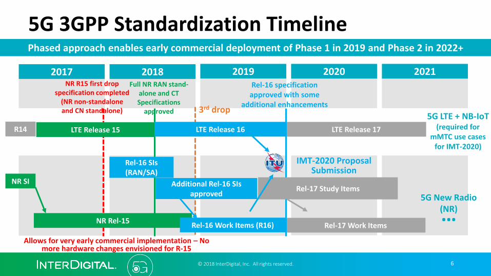
Virtual (Cloud) RAN Enablers
➢Standards efforts to enable virtualization in multi-vendor environments
• Central Unit / Distributed Unit split
• CU/DU split below the PDCP
• CU performs user management and user data processing
• DU manages the radio and cell
• Control Plane/User plane split
• Central unit further split into virtual entities:
• User data processing and user/mobility control
• Support of lower layer split – no conclusion
• Some of the radio control function performed by the central unit
• Challenging due to ties with implementation
Virtualization gives operators a flexible network design reducing cost
16© 2018 InterDigital, Inc. All rights reserved.
CU
DU
Control Data
gNB
DU

17
NumerologyA numerology is defined by sub-carrier spacing and CP overhead
➢OFDM waveform in both UL &DL• Optimized CP-OFDM with high spectrum utilization
• Spectrum confinement techniques such as filtering and windowing
• Simplifies design for D2D, Massive MIMO reciprocity & IAB.
• DFT-s-OFDM for coverage-limited scenarios in UL
➢Scalable Numerology• Subcarrier Spacing (SCS) scales with the BW (15𝑘𝐻𝑧 ∗ 2𝑁)
• To support diverse spectrum bands and services
• To avoid processing complexity associated with a large FFT size
• Higher SCS -> Higher bands -> Shorter OFDM symbols• To address RF impairments in mmWave bands (e.g., Phase Noise),
enable analog beamforming in mmWave bands and, lower latency
• Lower SCS -> Larger cyclic prefix• More robust to the channel delay spread (e.g., Broadcast Service)
• To support narrow band transmissions for mMTC services
SCS [kHz] 15 30 60 120 240
OFDM Duration [µs] 66.67 33.33 16.67 8.33 4.17
CP Duration [µs] 4.69 2.34 1.17 0.58 0.29
Total Symbol [µs] 71.36 35.67 17.84 8.91 4.46
Slot Duration [µs] 1000 500 250 125 62.5
Band [GHz] < 6 < 6 < 6 < > 6 > 6
© 2018 InterDigital, Inc. All rights reserved.
15 kHz
30 kHz
60 kHz
120 kHz
50 MHz
400 MHz
Max BW
100 MHz
200 MHz

18
Frame StructureFlexible frame structure adapting to various bands, duplexing mode and service requirements
UL
UL
Ctrl
DL
UL
UL
Ctrl
DL
UL
Ctrl
Downlink-Centric Slot
➢Flexible Frame Structure• Flexible TTI Duration ▪ Scalable TTI enables efficient service multiplexing
o Symbols across different SCSs are aligned at the symbol boundaries
▪ Shorter TTI to support low latency application (e.g., URLLC)
o User can also be schedule on a fraction of a slot (i.e., Mini-slot)
▪ Longer TTI to achieve higher spectral efficiency (e.g., eMBB)
o User can be scheduled on multiple-slots
• Flexible Scheduling▪ Both dynamic TDD and FDD are supported
▪ OFDM symbols in a slot can be DL, UL or flexible
▪ Flexible symbols can be used as gap or for forward compatibility
Uplink-Centric Slot
1
30 kHz
120 kHz
0
0
20 12 13
1 2 12 13
1 2 60 kHz
15 kHz
1 ms slot with 14 OFDM symbols
500 µs
250 µs
125 µs
OFDM symbol
Mini-Slot
Slot with load balancing
© 2018 InterDigital, Inc. All rights reserved.
Dynamic TDD

19
Hybrid Beamforming
© 2018 InterDigital, Inc. All rights reserved.
• Analog beamforming: phase shifter
• Digital beamforming: precoding matrix BB
RF
RF
BB
RF
RF
𝐲 = 𝐇 𝐱 + 𝐧
where 𝐱 = 𝐅𝐬 = 𝐅RF𝐅BB𝐬
s
𝐅RF
𝐅BB
Phase shifter
Tradeoff between cost and flexibility

Massive MIMO
➢ Conjugate Beamforming• Coherent combining at receiver
➢ For TDD, no performance loss when the number of antennas is much larger than the number of users (M/K → ∞)• Leverage channel reciprocity
• Result of Law of Large Numbers
➢ Pilot contamination• In mobile scenarios the channel
changes over time
• Contamination occurs when two users use the same pilot
Original Work by Thomas L. Marzetta (2006)
© 2018 InterDigital, Inc. All rights reserved.
k
20

Massive MIMO
➢ Enhanced CSI Feedback• Multi-resolution CSI
• Low spatial resolution with a linear precoder targeting SU-MIMO operation (Type-I CSI) low latency and overhead
• High spatial resolution with a linear combination precoder targeting MU-MIMO operation (Type-II CSI) better performance
• Flexible CSI reporting timing• CSI reporting timing can be dynamically indicated to optimize
latency based on CSI computational complexity
• Hybrid beamforming support• Joint CSI reporting of beam index and precoding matrix index (PMI)
➢ Enhanced UL Transmission • Non-Codebook based UL transmission
• Introduced in NR to enable UL reciprocity functionality in TDD
• UE determines its PUSCH precoder with some gNB assistance
Work under 3GPP
: DL control to trigger aperiodic CSI reporting
: UL channel for aperiodic CSI reporting
Low latency CSI High latency CSI
Slot #n Slot #n+1 Slot #n+2 Slot #n+3 Slot #n+4
• gNB can dynamically indicate the CSI reporting timing
© 2018 InterDigital, Inc. All rights reserved.
1) CSI-RS3) DL Control
2) Sounding Signal4) Precoded UL Data
PrecoderCalculation
21

22
Beam Management
➢ Beam management for high frequency• Support of high frequency spectrums (up to 52.6GHz) in NR
which is different from LTE
• Beam management is used to maintain optimal Tx/Rx beam pairing for control and data channels
➢ Beamformed Initial Access• Fundamental difference with LTE RACH lies on beamforming
• Beam association between RACH and SS/PBCH blocks
• UE selects an associated UL RACH resource of a selected DL SS block based on L1-RSRP measurements
Management of analog beams at Tx/Rx is newly introduced in NR
© 2018 InterDigital, Inc. All rights reserved.

23
Beam Failure Recovery
➢ Recovery from beam failure• Beam-based system is susceptible to blockage, UE rotation,
and mobility
• Link fails when Tx-Rx beams for DL control channel are mismatched• RLF has been used in LTE when link fails but that requires a restart
from initial access procedure high latency
• Beam recovery recovers beams for DL control channel • UE monitors quality of DL control channel beam and indicates new
candidate beam using a dedicated PRACH resource when link failed
• Beam recovery is used to recover the link before RLF low latency
A new mechanism introduced to handle frequent Tx/Rx beam mismatch
Beam failure due to blockage
New candidate beam
PR
AC
H f
or
bea
m 1
PR
AC
H f
or
bea
m 2
PR
AC
H f
or
bea
m 3
UE sends PRACH resource associated with new candidate beam to trigger beam recovery
© 2018 InterDigital, Inc. All rights reserved.

Ultra-Reliable and Low-Latency Communications
NR introduced several mechanisms to enable URLLC
24© 2018 InterDigital, Inc. All rights reserved.
Low Latency
DL Data
UL
Ctrl
Gap
HARQ-ACK
Slot
• Self-contained slot
Transmitting HARQ-ACK in the self-contained slot immediately after receiving the DL data
• Mini-Slot
Slot
Mini-Slot
Smaller time units for data scheduling
• Scalable subcarrier spacing
• Grant Free UL transmission
• Very low periodicity SR
• Pre-emption
High Reliability• Diversity via duplication
f1
f2
Same PDCP PDU on two carriers
Carrier-Aggregation
LTE NR
Same PDCP PDU over different RAT (DC)
Dual-Connectivity (EN-DC)
• Control channel duplication• Polar coding for control information • Optimized CQI/MCS tables

25
Channel Coding: Data Channel
➢ Enhanced LDPC Codes for eMBB Data Channel• Advantages of LDPC codes
• Support high data rates (NR peak data rate: 20 Gbps DL/10 Gbps UL)
• High area and energy efficiency and good BLER performance
• Quasi-cyclic LDPC code enables high degree of parallelism • Parity-check matrix is lifted from small base graph
• Two base graphs• Optimized for different regions of code rates and code block sizes
• Length and rate flexibility• Shortening and lifting to achieve 1-bit granularity on code block size
• Circular buffer with puncturing and repetition to achieve codewordlength flexibility;
• Support for both CC-HARQ and IR-HARQ
➢Future Enhancements • Potential modifications for URLLC data channel to address the error floor
and achieve high reliability
Channel coding was entirely redesigned for NRLTE: Turbo NR: LDPC
Throughput Medium-low High
Area efficiency Low High
Energy efficiency Low High
Implementation complexity comparison (R1-167567)
Coverage regions of 2 LDPC base graphs
© 2018 InterDigital, Inc. All rights reserved.
R=1/4
R=2/3
R=0.95
308 3840 Code block size
Code rate
8448
Base Graph 1
Base Graph 2

Channel Coding: LDPC
• Generator matrix
• Parity check matrix
© 2018 InterDigital, Inc. All rights reserved. 26
A primer on linear block codes and Tanner graph representation
𝐺 =
𝑔11 𝑔12 … 𝑔1𝑛⋮ ⋮ ⋮ ⋮
𝑔𝑘1 𝑔𝑘2 … 𝑔𝑘𝑛=
𝒈1⋮𝒈𝑘
𝒈1, 𝒈2, …, 𝒈𝑘 are linearly independent vectors of length 𝑛
k information bits 𝒖 = (𝑢1, 𝑢2, …,𝑢𝑘) mapped to a 𝑛-bit codeword:
𝒙 = 𝒖 𝐺 = 𝑢1𝒈1 + 𝑢2𝒈2+ …+𝑢𝑘𝒈𝑘
𝐻: (𝑛 − 𝑘) × 𝑛 matrix, each row is orthogonal to rows of 𝐺
Any codeword 𝒙 satisfies: 𝒙𝐻𝑇 = 0
• Tanner graph
𝐻 =1 0 1 00 1 1 1
x1+ x3 = 0
x2 + x3 + x4 = 0
x1
x2
x3
x4

Channel Coding: LDPC
• Binary Erasure Channel
© 2018 InterDigital, Inc. All rights reserved. 27
An example of message passing decoding
x1+ x3 = 0
x2 + x3 + x4 = 0
1
x2=?
x3=?
0
1
0
1
1
1

Channel Coding: LDPC
• Parity check matrix H• Base graph (matrix of 0’s and 1’s)
• Replace 1 with a cyclically shifted ZxZ identify matrix
• Replace 0 with a ZxZ all-zero matrix
Example:
© 2018 InterDigital, Inc. All rights reserved. 28
1 1 0 1 1 0
0 1 1 0 1 0
1 0 1 0 0 1
3 2 N/A 2 1 N/A
N/A 3 1 N/A 0 N/A
1 N/A 3 N/A N/A 0
1 0 0 0
0 1 0 0
0 0 1 0
0 0 0 1
0 0 0 1
1 0 0 0
0 1 0 0
0 0 1 0
Shift 3 positions 0 0 0 11 0 0 00 1 0 00 0 1 0
0 0 1 00 0 0 11 0 0 00 1 0 0
0 0 0 00 0 0 00 0 0 00 0 0 0
0 0 1 0
0 0 0 1
1 0 0 00 1 0 0
0 1 0 0
0 0 1 0
0 0 0 11 0 0 0
0 0 0 00 0 0 00 0 0 00 0 0 0
First row of base graph results in the first 4 rows of H:
Source: 3GPP TR 38.802, Study on New Radio Access Technology -- Physical Layer Aspects V14.0.0 (2017-03)
This construction is sometimes called lifting.
Parity check matrix construction in NR

29
Channel Coding: Control Channel
➢ Polar Codes for Control Channel and Broadcast Channel• Advantages of Polar codes
• Good BLER performance at small block sizes and no error floor
• Polar codes are used to encode DCI, UCI (>11 bits) and MIB
• A single nested polar sequence• Short polar sequence is derived from long polar sequence
• Optimized Rate Matching (RM) scheme • Select among three RM schemes: puncturing, shortening, repetition
• Unified circular buffer design for all three RM schemes
• Triangular channel interleaver (UCI only)
• Advanced polar code construction• Distributed CRC for DCI and MIB to achieve early termination
• Parity check polar code for small size UCI for better performance
➢Future Enhancements • Extension of polar code for URLLC data channel
NR is the first commercial system adopting Polar codes
Unified circular buffer design for three RM schemes
Polar Encoder (Mother
code length N)
Sub-block
0
Sub-block
1
Sub-block
31
Sub-block
0
Sub-block
1
Sub-block
31
Sub-block wise interleaving
Circular buffer
ShorteningRepetition
Puncturing
Selecting bits from the unified circular buffer
Rate matching
© 2018 InterDigital, Inc. All rights reserved.

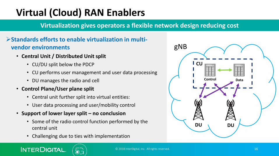
Channel Coding: Polar code
• Invented by Erdal Arikan in 2007
• Based on the phenomena of channel polarization
© 2018 InterDigital, Inc. All rights reserved. 30
WX Y
1. Binary Discrete Memoryless Channel (DMC)
2. Consider N copies of the DMC, and channel code X = GU
WX1 Y1
WX2 Y2
WXN YN
...
G
U1
U2
UN
...
...
Information bits codeword 𝐼 𝑈1, 𝑈2, … , 𝑈𝑁; 𝑌1, 𝑌2, … , 𝑌𝑁
=
𝑖=1
𝑁
𝐼 𝑈𝑖; 𝑌1, 𝑌2, … , 𝑌𝑁 𝑈1, … , 𝑈𝑖−1
=
𝑖=1
𝑁
𝐼(𝑈𝑖; 𝑌1, 𝑌2, … , 𝑌𝑁,𝑈1, … , 𝑈𝑖−1)
൯𝑊𝑖: 𝑈𝑖→ (𝑌1, 𝑌2, … , 𝑌𝑁,𝑈1, … , 𝑈𝑖−1New channels
Transform scalar channels into equivalent vector channels
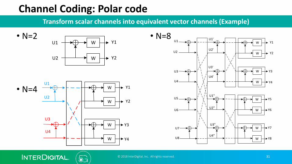
Channel Coding: Polar code
• N=8
© 2018 InterDigital, Inc. All rights reserved. 31
Transform scalar channels into equivalent vector channels (Example)
• N=2
• N=4
W
W
Y1
Y2
U1
U2
W
W
W
W
Y1
Y2
Y3
Y4
U1
U2
U3
U4
W
W
W
W
W
W
W
W
U1'
U2'
U3'
U4'
U1"
U2"
U3"
U4"
Y1
Y2
Y3
Y4
Y5
Y6
Y7
Y8
U1
U2
U3
U4
U5
U6
U7
U8

QoS Provisioning
• 4G: there are 9 pre-defined QoS Class Identifier (QCI) values
© 2018 InterDigital, Inc. All rights reserved. 32
By a combination of QCI, ARP, GBR/Non-GBR
Source: 3GPP TS 23.203, v11.2.0, “Policy and charging control architecture”, June, 2011.
QCI Resource Type
Priority Packet Delay Budget
Packet Error LossRate
Example Services
1
GBR
2 100 ms 10-2 Conversational Voice
2 4 150 ms 10-3 Conversational Video (Live Streaming)
3 3 50 ms 10-3 Real Time Gaming
4 5 300 ms 10-6 Non-Conversational Video (Buffered Streaming)
5
Non-GBR
1 100 ms 10-6 IMS Signalling
66 300 ms 10-6
Video (Buffered Streaming)TCP-based (e.g., www, e-mail, chat, ftp, p2p file sharing, progressive video, etc.)
77 100 ms 10-3
Voice,Video (Live Streaming)Interactive Gaming
88 300 ms 10-6
Video (Buffered Streaming)TCP-based (e.g., www, e-mail, chat, ftp, p2p file sharing, progressive video, etc.)9 9
GBR: Guaranteed Bit RateARP: Allocation and Retention Priority
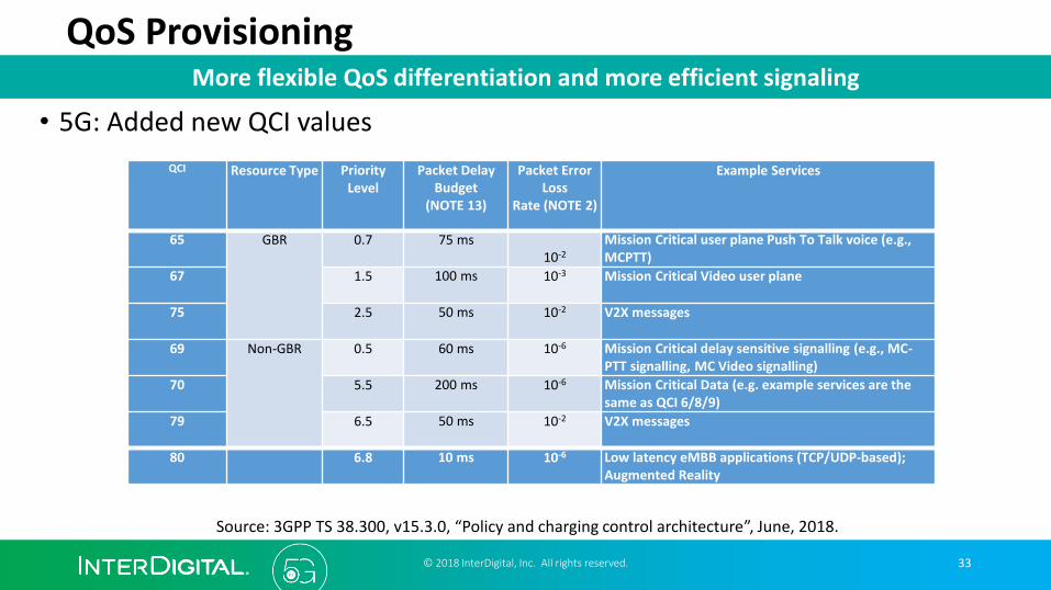
QoS Provisioning
• 5G: Added new QCI values
© 2018 InterDigital, Inc. All rights reserved. 33
More flexible QoS differentiation and more efficient signaling
Source: 3GPP TS 38.300, v15.3.0, “Policy and charging control architecture”, June, 2018.
QCI Resource Type Priority Level
Packet Delay Budget
(NOTE 13)
Packet Error Loss
Rate (NOTE 2)
Example Services
65 GBR 0.7 75 ms10-2
Mission Critical user plane Push To Talk voice (e.g., MCPTT)
67 1.5 100 ms 10-3 Mission Critical Video user plane
75 2.5 50 ms 10-2 V2X messages
69 Non-GBR 0.5 60 ms 10-6 Mission Critical delay sensitive signalling (e.g., MC-PTT signalling, MC Video signalling)
70 5.5 200 ms 10-6 Mission Critical Data (e.g. example services are the same as QCI 6/8/9)
79 6.5 50 ms 10-2 V2X messages
80 6.8 10 ms 10-6 Low latency eMBB applications (TCP/UDP-based);Augmented Reality

QoS Provisioning
• 5G: Added new QCI values
© 2018 InterDigital, Inc. All rights reserved. 34
More flexible QoS differentiation and more efficient signaling
Source: 3GPP TS 38.300, v15.3.0, “Policy and charging control architecture”, June, 2018.
QCI Resource Type
Priority Level
Packet Delay Budget
Packet Error LossRate
Maximum Burst Size
Data Rate Averaging Window
Example Services
82 GBR 1.9 10 ms 10-4 255 bytes 2 s Discrete Automation
83 GBR 2.2 10 ms 10-4 1358 bytes 2 s Discrete Automation
84 GBR 2.4 30 ms 10-5 1358 bytes 2 s Intelligent Transport Systems
85 GBR 2.1 5 ms 10-5 255 bytes 2 sElectricity Distribution-high voltage

QoS Provisioning
• 5G added SDAP (service data adaptation protocol) sublayer
• 5G introduced reflective QoS• Derive uplink QoS from downlink QoS
© 2018 InterDigital, Inc. All rights reserved. 35
More flexible QoS differentiation and more efficient signaling
RByRBx
IP Packet
H SDAP SDU
PDCP SDUH
RLC SDUH
MAC SDUH H
IP Packet
H SDAP SDU
PDCP SDUH
RLC SDUH
MAC SDU
IP Packet
H SDAP SDU
PDCP SDUH
SDU SegmentH
MAC SDU
SDU SegmentH
H H MAC SDU
...
...
...
...
MAC PDU – Transport Block
PDCP
RLC
SDAP
MAC
n n+1 m
Source: 3GPP TS 38.300, v15.2.0, “NR; NR and NG-RAN Overall Description”, June, 2018.
RB: Radio BearerPDCP: Packet Data Convergence Protocol

36
On-going and Future Work
© 2018 InterDigital, Inc. All rights reserved.

Outlook for Release 16 Core Network
© 2018 InterDigital, Inc. All rights reserved.
37
Release 16 aims to enable services intended to be supported by the 5G Core Network
37
5G Massive IoT (MIoT)
▪ Enable MTC and Cellular IoT functionalities in the 5G Core Network▪ MTC related features from Rel-10 to Rel-14 (e.g. Congestion
Control, Monitoring, Small Data Transfer, CP/UP Optimizations, Non-IP Data Delivery, etc…) shall be supported in 5GC
▪ Enhancements the 5G system to address Massive IoT (MIoT) use cases based on the initial 5G requirements
V2X services in 5G
▪ System enhancements of EPS and 5G to support advanced V2X Use cases:▪ Platooning, extended sensor sharing, enhanced
positioning accuracy, advanced driving and remote driving
Access Traffic Steering Switch and Splitting
▪ Multi-access (e.g. 3GPP and WLAN) PDU session management▪ Support traffic splitting between multiple accesses (e.g. 3GPP and
WLAN)▪ Switch traffic between multiple accesses
5G LAN Services▪ Enhancements to the 5G system to support 5GLAN service ▪ Support for 3GPP network that is not for public use and
for which service continuity and roaming with a PLMN is possible (a type network).
▪ Support an isolated 3GPP network that does not interact with a PLMN (b type network)

Non-Orthogonal Multiple Access (NOMA)
➢NOMA SI Objective
• NOMA involves purposely transmitting non-orthogonally and use of advanced receiver processing, leveraging the power difference, to recover the non-orthogonal signal.
• This technique allows for more transmission opportunities making it helpful in particularly helpful for mMTC.
• The study will look at the transmission schemes, receiver processing, procedures and evaluate the schemes for recommendation for specification.
• Official Study began Feb. 2018
NOMA is the key enabler for a new set of use scenarios in NR.
© 2018 InterDigital, Inc. All rights reserved. 38
Frequency
Time
TimeTime
Frequency
TDMA FDMA
NOMA

NR-Unlicensed (NR-U)
➢NR-U SI objectives:• Key PHY components: Inheriting choices of duplex mode,
waveform, carrier BW, SCS, frame structure, and PHY design made from NR study
• Spectrum: Consider below/above 6GHz up to 52.6GHz (and >52.6GHz if waveform design principles unchanged)
• Regulatory aspects (e.g. LBT): changes in initial access, channel access, scheduling/HARQ, mobility operation and radio-link monitoring/failure
• Coexistence: a) within NR, b) between NR- and LTE-based, c) with other incumbent RATs in accordance with regulatory requirements in e.g., 5GHz , 37GHz, 60GHz
• Possible deployments: a) Standalone NR-U, b) Carrier aggregation NR/NR-U and NR-U/NR-U, c) dual-connectivity between licensed NR/LTE and NR-U
NR-U can become the most efficient and flexible RAT for unlicensed bands
39
Band Availability Notes
800-900MHz No global availability Some incumbents
2.4GHz Global availability Many incumbents
3.7-4.2GHz 500MHz, US Under discussion
5.1-5.9GHz Global availability 11a/n/ac/ax, LAA
5.9-6.4GHz 0.5/1.2GHz, EU/US Under discussion
3.5GHz GAA 150 MHz, US Under discussion
57-71 GHz 14GHz 11ad
Some UEs are exposed to DL from
own/foreign gNB
© 2018 InterDigital, Inc. All rights reserved.

Non-Terrestrial Networks (NTN)
➢NTN SI focus
• Space-borne (GEO, MEO, LEO) vehicles as well as HAPS (High Altitude Platform Stations).
• The scope of the current study is to adapt the terrestrial channel model to non-terrestrial networks, and define the relevant deployment scenarios and their impact on NR.
➢NTN Challenges • Very high propagation delay (up to 250 mSec one-way
trip)
• Large cell sizes
• Moving cells
• Very high speed mobility (1000 km/hr)
• Service continuity during handover between NTN and TN
Benefits offered by NTN: wide area coverage, high capacity, and high reliability/availability
40
Handheld or IoT device
HAPS
Spaceborne Platform
NR gNB
© 2018 InterDigital, Inc. All rights reserved.
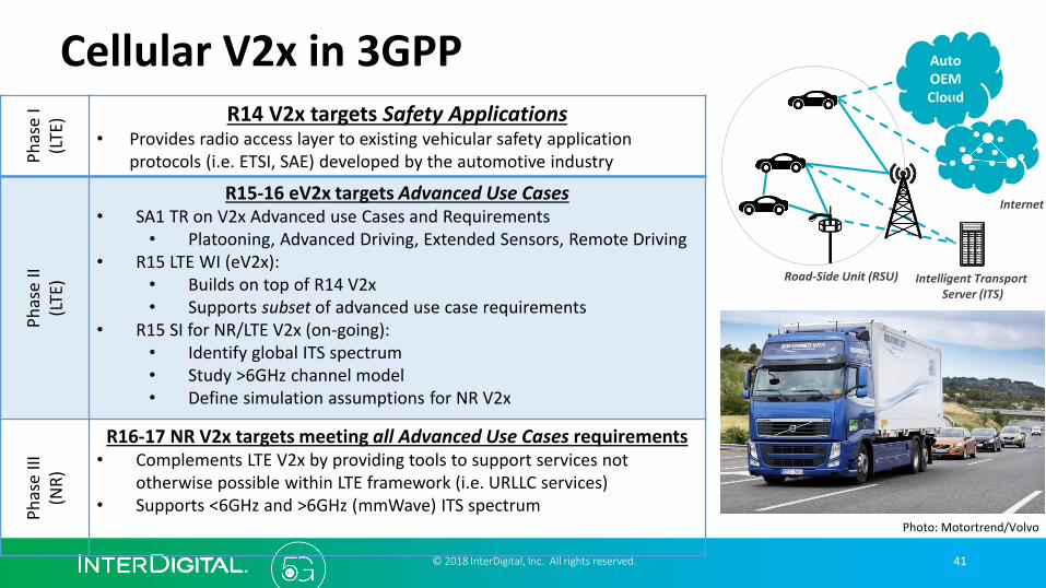
41
Cellular V2x in 3GPPP
has
e I
(LTE
) R14 V2x targets Safety Applications• Provides radio access layer to existing vehicular safety application
protocols (i.e. ETSI, SAE) developed by the automotive industry
Ph
ase
II(L
TE)
R15-16 eV2x targets Advanced Use Cases• SA1 TR on V2x Advanced use Cases and Requirements
• Platooning, Advanced Driving, Extended Sensors, Remote Driving• R15 LTE WI (eV2x):
• Builds on top of R14 V2x• Supports subset of advanced use case requirements
• R15 SI for NR/LTE V2x (on-going): • Identify global ITS spectrum• Study >6GHz channel model• Define simulation assumptions for NR V2x
Ph
ase
III(N
R)
R16-17 NR V2x targets meeting all Advanced Use Cases requirements• Complements LTE V2x by providing tools to support services not
otherwise possible within LTE framework (i.e. URLLC services)• Supports <6GHz and >6GHz (mmWave) ITS spectrum
Photo: Motortrend/Volvo
Internet
Intelligent Transport Server (ITS)
Road-Side Unit (RSU)
Auto OEM Cloud
© 2018 InterDigital, Inc. All rights reserved.

Features to be brought over from LTE in the future
➢Broadcast/Multicast (MBMS)
• Will add Broadcast on dedicated spectrum (TV like) to shared spectrum service like MBMS
Features brought over from LTE including Identification of New Use Cases
42© 2018 InterDigital, Inc. All rights reserved.
➢mMTC
• In LTE - main use cases treated were many users with low data requirements, low power, and wider reception areas. Use cases like video surveillance can’t be done in LTE
• Another part of the work will be to have co-existence between NR and NB-IoT in the same spectrum bands.
➢Voice in 5G standalone networks• Avoid techniques used in early 4G (circuit switch
fall back to 3G)
• Also looking at enhancing multimedia video calls.
➢UE Positioning
• Tighter 5G Requirements:
• Accuracy of < 1m & higher speeds (>100km/h)
• Low altitude positioning (UAV)
• Improve indoor & high density mMTCpositioning
• Less energy consumption in UE for positioning
• Use of GPS, Wi-Fi, existing LTE techniques and New NR techniques

43
Case study – remote surgery
© 2018 InterDigital, Inc. All rights reserved.

Remote surgery
© 2018 InterDigital, Inc. All Rights Reserved. 44
Source of the two images: The surgeon who operates from 400km away, BBC, May 16, 2014
SurgeonsRobot & patient
Surgeon’s Action
Tissue responses (visual, tactile)
Mobile Surgery Vehicle

• Commercial robot surgery products: Intuitive Surgical’s da Vinci Surgical System• Approved by FDA
Remote surgery
© 2018 InterDigital, Inc. All Rights Reserved. 45
Source: https://www.intuitivesurgical.com/products/davinci_surgical_system/features_benefits/
Surgeon Console Endowrist HD Vision

Remote surgery
© 2018 InterDigital, Inc. All Rights Reserved. 46
Requirement: Command to video feedback delay < 5 ms
Assuming a distance of 50km, we derive the system requirements• Communication system: < 1ms latency at the air interface• Video codec: high-definition, high frame rate ~1000 frames/sec
To get a feel about what latency is needed, watch the video on user interface latency of Microsoft’s 1ms touch screen, March 2012
https://www.youtube.com/watch?v=vOvQCPLkPt4 [Start at 52 seconds]

• What DL latency LTE can offer?
47
Remote surgery
© 2018 InterDigital, Inc. All Rights Reserved.
N-1 N N+1 N+2 N+3 N+4 N+5 N+6 N+7eNB
N-1 N N+1 N+2 N+3 N+4 N+5 N+6 N+7UE DL
DATA
N-1 N N+1 N+2 N+3 N+4 N+5 N+6 N+7UE UL NACK
N+8 N+9
N+8 N+9
N+8 N+9
RTX
ACK
Timing advance
delay2ms
0.9
0.1
probability
8ms
With probability 0.1
1 TTI=1ms
This does not meet the delay requirement

• 5G NR latency (DL data transmission)
48
Remote surgery
© 2018 InterDigital, Inc. All Rights Reserved.
N-1 N N+1 N+2 N+3 N+4 N+5 N+6 N+7gNB
N-1 N N+1 N+2 N+3 N+4 N+5 N+6 N+7UE DL
DATA
N-1 N N+1 N+2 N+3 N+4 N+5 N+6 N+7UE UL NACK
N+8 N+9
N+8 N+9
N+8 N+9
RTX
ACK
Timing advance
delay0.284ms
1- 10-5
10-5
probability
0.568ms
With probability 10-5
1 mini-slot = 142µs (2 OFDM symbols)
What delay 5G can offer?

49
What about the core network? – A measurement study• Ping between two points in San Diego
• Distance < 9.5 miles
• Propagation delay < 0.15ms
• Average RTT = 37ms, but ideally it should be < 0.32ms• Assume transmission speed > 10 Mbps in the ideal case
• Why is the 100x difference? Number of hops = 15!
XO Communications
Time Warner Cable
CENIC
UCSD
© 2018 InterDigital, Inc. All Rights Reserved.

50
What about the rest? – A measurement study
• App. data packet size: 100 bytes, 1-meter long, 1Gbps Ethernet cable
• Transmission delay: dt= (100+8+20+26)*8bits/(1Gbps)= 1.232µs
• Propagation delay: dp=1/(2x108)=(1/200) µs
• Average processing delay in the end devices in a round trip: RTT - dt -dp=0.175 milliseconds
UDP header IP header PHY preamble + MAC header + CRC
© 2018 InterDigital, Inc. All Rights Reserved.

Potential Solutions
• Reduce latency in the core network• Software Defined Networking (SDN)
• Reduce latency in the local area network• Industrial Ethernet
• Reduce latency on the end devices• Real-time operating system
• FPGA or dedicated hardware for communication interrupts
© 2018 InterDigital, Inc. All Rights Reserved. 51

52
Commercialization
© 2018 InterDigital, Inc. All rights reserved.

• Fixed Wireless Access (WFA)• Do not need frequent changes in beamforming
• Large user base (can potentially replace the cable TV/Internet services)
• Celluar-V2X• Large user base
• High-value market
• Industrial IoT• Extreme QoS requirements
• High-value market
• AR/VR
Killer applications?
© 2018 InterDigital, Inc. All Rights Reserved. 53
We wish to have a crystal ball to see the future!

• Chip companies have released 5G modem platforms
• 3GPP spec for 5G Phase I was frozen in June 2018
• Commercial deployments are expected in the second half of 2019
Where are we?
© 2018 InterDigital, Inc. All Rights Reserved. 54
First commercial deployment is coming in about a year!

55
Thank You!
© 2018 InterDigital, Inc. All rights reserved.