Embed Size (px)
Citation preview

1
5G Millimeter-Wave and D2D Symbiosis:60 GHz for Proximity-based Services
Gek Hong Sim[ Adrian Loch† Arash Asadi[ Vincenzo Mancuso† Joerg Widmer†[Technical University of Darmstadt, Germany†IMDEA Networks Institute, Madrid, Spain
Abstract—The characteristics of two key communica-tion technologies in 5G, namely, Device-to-Device (D2D)and millimeter-wave (mmWave), are complementary. WhileD2D facilitates the communication of nearby mobile nodes,mmWave provides very high throughput short-range linksby using carrier frequencies beyond 30 GHz, and reducesinterference by using directional communication. This directlyaddresses two critical issues in cellular networks, namely, theincreasing number of users and the high throughput require-ments. In this paper, we explore the above symbiosis of D2Dand mmWave. More precisely, we integrate mmWave commu-nications into the 3GPP framework for D2D communication,i.e., Proximity-based Services. To this end, we design themessage exchange among entities in the ProSe Architectureto support the discovery, establishment and maintenance ofmmWave links. Further, we evaluate the performance of ammWave D2D system for the case of a picocell operatingin the 60 GHz band. We experimentally analyze the benefitsof combining D2D and 60 GHz communication. Our resultsshow that this combination improves performance in terms ofthroughput by up to 2.3 times.
I. INTRODUCTION
The requirements for a 5G cellular network architecturediffer substantially from those of its predecessors, amongothers due to the support of the Internet of Things (IoT)and the giant leap in the number of connected devices.As a result, 5G cellular networks promise not only anorder-of-magnitude increase in bandwidth but also an en-hanced network architecture that is tailored to the servicesexpected from today’s cellular infrastructure. One of thesignificant architectural enhancements is Device-to-Device(D2D) communication [1] that allows mobiles to establisha direct connection without traversing the eNodeB. D2D isa key component in the context of IoT, since a substantialfraction of the traffic is generated and consumed locally.Thus, eliminating the eNodeB from the transmission pathleads to higher spectral efficiency, lower signaling overhead,and higher energy efficiency. However, these gains can onlybe achieved if we can overcome several challenges facedby D2D communication.
The main problem in D2D communication, also knownas Proximity-based Services (ProSe) in 3GPP’s terminol-ogy, is interference management. Depending on the spec-trum resources used for D2D communication, one facesdifferent flavors of interference related issues. On the onehand, if D2D users communicate over ISM bands usingtechnologies such as WiFi [2], they may have to compete
with many other devices for channel access and there islittle control over the interference encountered in thesebands. Hence, QoS guarantees and transmission reliabilitymay become an issue. On the other hand, using licensedspectrum provides much more control over the radio envi-ronment and thus facilitates more reliable communication,but it requires accurate interference management amonglegacy cellular communications and D2D communications.Prior studies proposed several techniques for addressing theaforementioned concerns. Nevertheless, D2D link capacityis significantly affected by the network density, no matterwhich of these prior solutions is used. This limitationis due to the fact that the current technologies for D2Dcommunication are not ideal for proximity-based directcommunication because they (i) have insufficient band-width, and (ii) they cause significant interference due tothe omni-directional nature of communication.
In this paper, we elaborate on the symbiosis between twokey technologies in 5G: millimeter-wave (mmWave) andD2D communications. We believe that the characteristicsof mmWave such as high pathloss [3], which requiresdirectional beamforming for higher channel gain, is a per-fect fit for D2D communication. This directional transmis-sion tremendously decreases the interference and enablesextreme spatial sharing [3], [4]. Thus, high bandwidthmmWave paves the way for extremely high throughput D2Dapplications without interfering with existing cellular users.Also, short range directional links make mmWave D2Dcommunication much less susceptible to network density.
Related work studies beamforming for D2D [5], [6]in the context of Multiple-Input-Multiple-Output (MIMO)communication. While some of the benefits in that casealso apply to D2D at 60 GHz, the key difference is that 60GHz communication typically uses codebook-based analogbeamforming. That is, instead of using Channel StateInformation (CSI) to shape their beampattern such thatinterference is minimized, 60 GHz D2D transmitters mustchoose out of a predefined set of beampatterns. Althoughthis alleviates constraints on CSI feedback, it also meansthat avoiding interference becomes more challenging. Sev-eral research groups have explored this mmWave D2Dspatial reuse in earlier work. Al-Hourani et al. [7] examinethis potential by means of simulation based on ray-tracingfor the case of ISM bands. In [8], Qiao et al. investigate aresource sharing mechanism which enables non-interferingD2D and multi-hop links to operate concurrently. Further,
the gain of mmWave transmission for joint access andbackhaul is presented in [9]. Recent work also studiesanalytically the interference of D2D communication inhome networks [10]. The aforementioned works discussseveral prominent aspects of integrating mmWave and D2Dcommunications. In this work, we take a further step by(i) integrating mmWave into the 3GPP ProSe framework,and (ii) evaluating the feasibility and performance of thisconcept by conducting a practical testbed evaluation.
II. MMWAVE AND D2D SYMBIOSIS
Using the mmWave spectrum poses several challenges. Inthe following, we will show that some of these challengesare in fact desirable features for D2D communication.
A. High pathloss
mmWave transmissions experience very high path loss,which is the reason why this part of the spectrum is start-ing to be explored for consumer telecommunication onlyvery recently. To counter the high path loss, beamformingtechniques are widely used for mmWave transmissions toachieve the desired communication range. Nevertheless, thetheoretical range for mmWave is still below 50 meters(for consumer-grade off-the-shelf 60 GHz devices [11]).Interestingly, this shortcoming is an advantage for D2Dcommunication as it helps to limit interference – a keyissue in D2D communication. Due to lack of capacity andincreased user demand, eNodeBs usually cover a small area.Moreover, small cell deployments are becoming more andmore common. In particular, when D2D communicationoccurs over cellular spectrum, power control and interfer-ence management become very complex. As a result, morefrequent feedback and control messages are required. Incontrast, mmWave does not impose such interference issuesand it perfectly matches the envisioned transmission rangefor D2D communications.
B. Directional Transmissions
mmWave transmissions are highly directional due to theuse of beamforming to compensate for the high path loss.This path loss is primarily caused by the carrier frequencydependent attenuation, and secondarily by oxygen absorp-tion. Beamforming in mmWave is typically codebook-based, that is, nodes use a predefined set of possiblebeam patterns. For high rate communication, the beampatterns of a pair of communicating nodes need to bevery well aligned. In scenarios in which a single basestation communicates with tens of randomly distributedmobile users, maintaining this alignment is challenging.Also beam-steering to cover all spatial directions, either forneighbor discovery or distribution of common information,induces high overhead. Due to the smaller number ofusers that communicate directly and the close proximity,the overhead issues caused by directionality are tremen-dously reduced for D2D communication. In fact, directionaltransmissions are advantageous for D2D communication as
EPC 3rd party networkEUTRAN
ProSe
Function
ProSe Application
Server
eNodeB
S-GW P-GW
HSS
MMEProSe
ApplicationProSe
Application
Internet
User plane
Control plane
UEUE
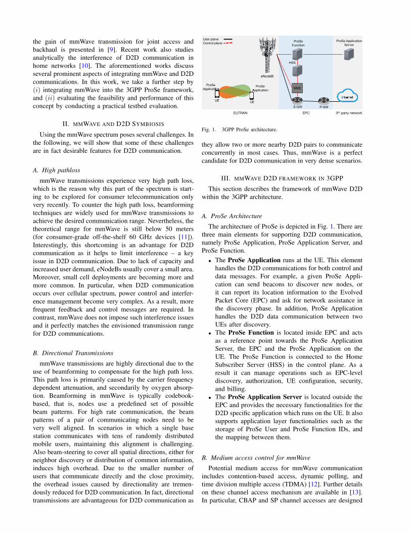
Fig. 1. 3GPP ProSe architecture.
they allow two or more nearby D2D pairs to communicateconcurrently in most cases. Thus, mmWave is a perfectcandidate for D2D communication in very dense scenarios.
III. MMWAVE D2D FRAMEWORK IN 3GPP
This section describes the framework of mmWave D2Dwithin the 3GPP architecture.
A. ProSe Architecture
The architecture of ProSe is depicted in Fig. 1. There arethree main elements for supporting D2D communication,namely ProSe Application, ProSe Application Server, andProSe Function.
• The ProSe Application runs at the UE. This elementhandles the D2D communications for both control anddata messages. For example, a given ProSe Appli-cation can send beacons to discover new nodes, orit can report its location information to the EvolvedPacket Core (EPC) and ask for network assistance inthe discovery phase. In addition, ProSe Applicationhandles the D2D data communication between twoUEs after discovery.
• The ProSe Function is located inside EPC and actsas a reference point towards the ProSe ApplicationServer, the EPC and the ProSe Application on theUE. The ProSe Function is connected to the HomeSubscriber Server (HSS) in the control plane. As aresult it can manage operations such as EPC-leveldiscovery, authorization, UE configuration, security,and billing.
• The ProSe Application Server is located outside theEPC and provides the necessary functionalities for theD2D specific application which runs on the UE. It alsosupports application layer functionalities such as thestorage of ProSe User and ProSe Function IDs, andthe mapping between them.
B. Medium access control for mmWave
Potential medium access for mmWave communicationincludes contention-based access, dynamic polling, andtime division multiple access (TDMA) [12]. Further detailson these channel access mechanism are available in [13].In particular, CBAP and SP channel accesses are designed

Discovery
eNodeBUE2 ProSe FunctionUE#1#has active##connection#with#Prose#Application#Server
UE1
Location#Update
Registration#Confirmation#&#Setting
Registration#RequestRegistration#Request
Registration#Confirmation#&#Setting
Location#UpdateLocation#UpdateLocation#Update
Proximity#Alert#(UE#IDs)Proximity#Alert#(proximate#UE#ID/AoA)
Proximity#Alert#(proximate#UE#ID/AoA)
Proximity#Alert
Termination#Request Termination#Request Termination#Request
Registration
ProSeApplication Server
Termination
mmWave
LinkBSetup
BeamsteeringD2D#Link#Ready D2D#Link#Ready
mmWave
LinkBMaintenance
mmWave CSI mmWave CSI
mmWave InterferenceBControl
mmWave CSI mmWave CSI
Termination#NotificationTermination#Notification
Termination#Notification
D2D#Link#Ready
Fig. 2. Our envisioned mmWave ProSe signaling using EPC-level discovery.
such that multiple directional transmissions are allowed tosimultaneously transmit/receive. Therefore, we deem thesechannel access mechanisms the most suitable candidates forD2D communication.
In the current architecture for D2D communication, con-current channel access is only possible if the D2D transmis-sions are far from each other in order to avoid interference.As we discuss in the next subsection, directional commu-nication enables concurrent transmission between differentD2D pairs in proximity without incurring significant mutualinterference. Thus, a high gain is expected by substitutingthe legacy WiFi/cellular D2D links with mmWave links. Asa result, network throughput can be improved substantially.
C. mmWave D2D in ProSe Architecture
There are five phases to setup, initiate and complete ammWave D2D transmission. Fig. 2 illustrates each phaseand its associated signaling message exchange and proce-dures. In the following, we explain these phases.
Registration Phase. D2D users should register for themmWave D2D service at the ProSe Application Server.This helps speeding up the mmWave connection setup uponsuccessful discovery since the server can provide to eachnode of a node pair the coarse location of the other node,thus reducing the time required for beam search. Further,registration is necessary for D2D users that exploit EPC-level discovery, as discussed in the next phase.
Discovery Phase. In this phase, a UE discovers anotherUE in proximity prior to the initiation of communication.3GPP specifies two options for discovery: direct discoveryand EPC-level discovery. In direct discovery, a UE usingdirectional communication transmits beacons sequentiallyas it sweeps in all directions. This procedure is similar toexisting mmWave protocols, such as IEEE 802.11ad. The
EPC-level discovery procedure is a centralized approachwhich allows discovering another UE in proximity basedon the location obtained from each UE, which is stored inthe ProSe Application Server. For brevity, we only illustratethe discovery phase using EPC-level discovery in Fig. 2.
While direct discovery allows out-of-range UEs to obtainassistance from a UE closer to the BS, the EPC-level dis-covery reduces energy consumption. Further, it minimizesoverhead and interference incurred by periodical controlmessage transmissions. In particular, we propose sendingthe estimated Angle of Arrival (AoA) along with proximityalerts to the UEs. AoA could be estimated by the ProSeApplication Server based on the location information. ThisAoA information can significantly speed up the beamsteer-ing and the connection setup phase, as mentioned earlier.
mmWave Link Setup Phase. After successful discovery,the pair of D2D nodes can set up a D2D link for datatransmission. Prior to any data transmission, the UEs haveto perform beamsteering. In this stage, the UEs limit theirbeam training to the estimated AoA they received from theProSe Application Server, thus saving valuable connectiontime. If needed, further beam refinement can be performed.Then the UEs transmit a D2D Link Ready message tothe ProSe Function. Once acknowledged, the D2D datatransmission can be initiated.
mmWave Link Maintenance Phase. Given the dynamicnature of D2D communication, UEs may change positionor new D2D UEs may join or leave the system. As aresult, a coarse central management is necessary to ensurea consistent system performance. Therefore, we proposetwo mechanisms. First, we suggest regularly sending coarseaverage CSI from the UEs to the ProSe Application Server,that is, mmWave link characteristics such as signal-to-noiseratio. The time-scale at which this feedback takes place

can be adjusted to system needs. However, the minimumfeedback and averaging interval must be at least in the orderof the end-to-end delay to the ProSe application serverto avoid that outdated CSI arrives at the server. Second,we propose adding local interference control at the ProSeApplication Server to monitor the channel quality of themmWave D2D links in smaller neighborhoods and detectinterfering links.
Termination. If either of the D2D UEs wishes to stop theconnection, this intention should be reported to the ProSeApplication Server via a Termination Request message tothe eNodeB. If the ProSe Application Server decides thatthe D2D link has poor performance, it can send a Termina-tion Request to ask the UEs to continue the communicationthrough legacy cellular communication.
IV. EVALUATION
In this section, we evaluate the feasibility of mmWaveD2D communication in practice. Specifically, we useconsumer-grade off-the-shelf half-duplex devices operatingin the 60 GHz band, and focus on the impact of 60 GHzpropagation characteristics on D2D communication. Thisshows that mmWave D2D is not limited to experimentalhardware only but is beneficial also in real-world scenarios.
A. Evaluation scenario
We consider a scenario with two UEs and one eNodeB.In legacy D2D networks, the UEs can communicate witheach other using local area network technologies suchas 802.11n. Further, they communicate with the eNodeBusing, for example, LTE. However, 5G foresees the use ofmmWave communications not only for local networkingbut also for picocell coverage [14]. Hence, in our scenario,both the UEs and the eNodeB use the 60 GHz band tocommunicate. This matches, for instance, the case of apicocell eNodeB deployed on the facade of a building ina urban environment, and two mobile nodes located alongthe walkway in its proximity.
In our experiments, we evaluate the potential benefitsof mmWave D2D as described in the previous sections. Onthe one hand, we expect D2D to be beneficial for mmWavepicocells because it enables the eNodeB to provide betterservice to users which are at the cell edge. On the otherhand, we expect mmWave to be beneficial for D2D becauseits directional nature reduces interference among nearbylinks. Our evaluation scenario allows us to validate thissymbiosis by means of two experiments. In the first exper-iment, we place UE A partially occluded from the eNodeBby an obstacle. UE B has a Line of Sight (LOS) link to bothA and the eNodeB. Assuming that the ProSe Applicationrealizes this situation, UE A can establish a D2D connectionto UE B, which then relays the traffic to the eNodeB. Wecompare throughput with and without UE B acting as aD2D relay. In the second experiment, we consider a similarscenario but vary the spatial angle between the two linksinvolved in the communication. This allows us to assess thealleged interference improvement. Note that both the D2D
and the cellular link operate in the same mmWave bandand thus interfere with each other in both directions. Thebidirectionality of the interference is due to the physicallayer acknowledgements generated by the hardware.
B. Off-the-shelf 60 GHz D2D testbed
While major vendors have announced mmWave network-ing products in the coming months, at the time of writingsuch devices are not yet available. However, consumer-grade hardware operating in the unlicensed 60 GHz bandis widely available. For instance, wireless docking stationsystems such as the Dell D5000 follow the WiGig standardto connect a laptop wirelessly to external devices such as amonitor, a wired Ethernet connection, and input peripherals.The WiGig standard has led to 802.11ad, which is the802.11 amendment for mmWave communication. Hence,we exploit this existing hardware to set up a practical D2D60 GHz testbed. In particular, we use two D5000 dockingstations and two Dell Latitude E7440 notebooks. Each ofthem has a single 2x8 element antenna array. Further, eachpair of docking station and notebook establishes a 60 GHzlink. As shown in earlier work using this hardware [11],the link follows the standard both at the physical and atthe medium access control (MAC) layers. This includesmechanisms such as beamsteering, frame aggregation, andCSMA/CA. That is, it behaves similar to an 802.11ad linkwith the limitation that it operates point-to-point only.
To use the link, we connect (a) the Dell E7440 laptopvia 60 GHz to the docking station, and (b) the dockingstation via Ethernet to an additional laptop. This additionallaptop does not require 60 GHz networking capability butjust serves as an end point for the communication. Usinga networking tool (iperf1), we generate traffic among bothlaptops and thus on the link. This tool also displays theachieved throughput at the receiver. However, to recreatethe D2D scenario described in Section IV-A, we need toestablish two 60 GHz links. While the docking system doesnot allow for such a setup, we circumvent this limitationas shown in Fig. 3. Essentially, we extend the above setupadding an additional 60 GHz link and connecting it to theaforementioned Dell E7440 laptop via Ethernet. This laptopacts as UE B in Section IV-A. To allow UE B to relay datafrom the first to the second 60 GHz link, we simply bridgeits Ethernet and 60 GHz interfaces in the operating systemnetwork configuration. As a result, the laptop acting as theeNodeB can transmit data via UE B to UE A, and vice-versa, despite the limited capabilities of the hardware.
C. Experiment setup
Fig. 4 shows the lab setup for the two experimentsthat we describe in Section IV-A. In Experiment 1, weplace a metallic obstacle on the LOS path between theUE and the eNodeB. In Experiment 2, we remove theobstacle but move UE A along the dotted circle shown inFig. 4 to evaluate the interference between the D2D link
1Available at https://iperf.fr/

Ethernet+ Bridge
Ethernet
60 GHz 60 GHz
D2D Link Cellular link
UE A UE B
Fig. 3. Realization of the evaluation scenario in the testbed.
UE A
eNodeBUE B
d1
d2
d3
d4
d5
d6
Obstacle (Exp. 1)
d1 = 2.4 meters
d2 = 2.4 meters
d3 = 4.5 meters
d4 = 3.2 meters
d5 = 0.5 meters
d6 = 0.8 meters
= Measurement
Legend
point (Exp. 2)
1
2345
6
7
8
9
10
1112
13
14
15
Fig. 4. Experiment setup. The obstacle is only in place in Experiment 1.For that case, UE A is placed as shown in the figure. In Experiment 2,we place it at each of the locations marked with a black dot.
and the cellular link. This allows us to understand howthe interference among them changes depending on theirrelative position and angle. In particular, we place UE Aat each of the black dots. For each measurement, we alignthe Dell D5000 docking stations with their respective DellLatitude laptop. While both sides support beamsteering, thisallows for a fair comparison since the performance of theDell docking station system is known to become worsewhen beamforming sideways [11]. Moreover, we also resetthe 60 GHz connections prior to each measurement to avoidsuboptimal beamsteering as a result of moving UE A to thenext measurement point. This limits the uncertainty that thebeamsteering algorithm introduces—since the algorithm isimplemented in firmware, we cannot influence it.
D. Evaluation results
In the following, we describe and discuss the results ofthe two experiments presented in Section IV-A.
1) Experiment 1: Fig. 5 shows our results for Experi-ment 1. The average throughput when using D2D to relaytraffic to the eNodeB via UE B is approximately 200 Mbps.In contrast, the average throughput on the direct link isonly about 85 Mbps. That is, D2D provides a throughputgain of about 2.3× by avoiding the obstacle shown inFig. 4. In our case, communication is still possible via thedirect link. Still, an obstacle might also prevent mmWavecommunication entirely. In such a case, D2D relaying iscrucial for the operation of the picocell. In Fig. 5 we alsoobserve that the D2D connection is significantly more stablethan the direct uplink from UE A to the eNodeB. Thelarge fluctuations in the latter case are a result of UE A
0 10 20 30 40 50 600
50
100
150
200
Time [s]
Thr
ough
put [
mbp
s]
Direct connection Node A to APD2D connection Node A to AP via Node B
Fig. 5. Experiment 1. Throughput with and without a D2D relay.
continuously trying to improve its link quality by meansof rate adaptation and beamsteering. This even leads tooutages, as shown in Fig. 5 at seconds 19 and 42. Such largefluctuations significantly hinder the operation of upper-layerprotocols. Hence, Experiment 1 clearly shows that D2D isbeneficial for mmWave, contributing to the aforementionedsymbiosis.
2) Experiment 2: In our second experiment, we showhow mmWave reduces the interference in D2D. More pre-cisely, Fig. 6 shows a box-plot of our throughput measure-ments when placing UE A at each of the locations markedin Fig. 4. The horizontal mark on each box is the medianof our results for a certain location. We observe that themedian is at about 100 Mbps, or even below, for positions1 to 3, 6 to 9, and 12 to 15. From Fig. 4, we find that thesepositions correspond to the cases when the concurrent linksare roughly parallel or at a moderate angle towards eachother. In such cases, either the transmitter or the receiverof one link is approximately aligned with the transmitteror the receiver of the other link. This causes interferenceand thus reduces the throughput. The more narrow thebeamwidths, the less often this should happen. However,the beam patterns of the Dell docking station system areknown to be rather wide [11]. Hence, interference occursoften. However, when the links are at roughly 90◦ towardseach other, we expect interference to be low. Indeed, Fig. 6shows that for Position 4, the median rises to above 200mbps, resulting in a 2× throughput gain compared to, forinstance, Position 3. This shows that mmWave is highlybeneficial for D2D as it enables simultaneous operationof nearby links. Fig. 6 shows a second peak at Positions10 and 11, which corresponds to the same effect whenmoving UE A to the other side of the circle in Fig. 4.However, we would rather expect this peak at Position12, which is the symmetric location to Position 4. Thisasymmetry is a result of the irregular beam patterns of theD5000, which have significant sidelobes [11]. This showsthat the actual characteristics of consumer-grade off-the-shelf devices might result in unexpected effects, making itmore difficult to predict how devices will behave. If our 60

0
50
100
150
200
1 2 3 4 5 6 7 8 9 10 11 12 13 14 15Position on circle (c.f. Figure 4)
Thr
ough
put [
mbp
s]
Fig. 6. Experiment 2. Throughput for different link relative angles.
GHz devices would feature ideal pencil-beams, the secondpeak in Fig. 6 would occur at Position 12.
The whiskers of each box in Fig. 6 show the maximumand minimum throughput measurements at each location.For some cases, such as Positions 3 and 6, we occasionallyachieve high data rates but most of the times they arelimited by interference, as the median reveals. This occursat borderline locations, that is, at locations where thelinks are not parallel to each other anymore but also notperpendicular yet. In such cases, the algorithm that choosesthe beampattern at the docking station finds a numberof patterns that seem suitable to minimize interferenceduring communication. As a result, the docking stationmay choose a different beam pattern in each experimentrepetition, resulting in different performance. For instance,at Position 3, we sometimes achieve up to 200 Mbps butmost often throughput is about 65 Mbps. Unfortunately, wehave no influence on beam pattern selection. In other words,the docking station is not able to fully exploit the spatialresources. This highlights the need for more sophisticatedbeamsteering algorithms in future mmWave D2D hardware.
V. CONCLUSIONS
In this paper we integrate mmWave communication intothe 3GPP framework for D2D Proximity-based Services.We identify the benefits of D2D for mmWave, and vice-versa, showing that this symbiosis is highly promising. Onthe one hand, the directional nature of mmWave commu-nication helps mitigating the interference among nearbyD2D node pairs. On the other hand, the D2D ProSe Ap-plication Server can, for instance, provide coarse locationinformation which significantly reduces the mmWave linksetup time. Further, we perform the first practical evaluationof 60 GHz D2D using commercial off-the-shelf devices.We experimentally validate the aforementioned symbiosisof mmWave and D2D. Our results show that D2D canimprove the throughput of a 60 GHz picocell by 2.3 timeson average. Conversely, we find that reduced interferencein 60 GHz communication can improve D2D throughputperformance by two times.
ACKNOWLEDGEMENTS
This article is partially supported by the European Re-search Council grant ERC CoG 617721, the Ramon y Cajalgrant from the Spanish Ministry of Economy and Compet-itiveness RYC-2012-10788, the Madrid Regional Govern-ment through the TIGRE5-CM program (S2013/ICE-2919),and the LOEWE initiative (Hessen, Germany) within theNICER project.
REFERENCES
[1] A. Asadi, Q. Wang, and V. Mancuso, “A Survey on Device-to-DeviceCommunication in Cellular Networks,” IEEE CommunicationsSurveys & Tutorials, 2014.
[2] A. Asadi, V. Mancuso, and R. Gupta, “An SDR-based ExperimentalStudy of Outband D2D Communications,” in IEEE INFOCOM,2016.
[3] Y. Niu, Y. Li, D. Jin, L. Su, and A. Vasilakos, “A Survey ofMillimeter Wave (mmWave) Communications for 5G: Opportunitiesand Challenges,” CoRR, 2015.
[4] J. Karjalainen, M. Nekovee, H. Benn, W. Kim, J. Park, and H. Sung-soo, “Challenges and Opportunities of mm-wave Communicationin 5G Networks,” in International Conference on Cognitive RadioOriented Wireless Networks and Communications (CROWNCOM),Jun 2014.
[5] X. Lin, R. W. Heath, and J. G. Andrews, “The interplay betweenmassive mimo and underlaid d2d networking,” IEEE Transactionson Wireless Communications, vol. 14, no. 6, 2015.
[6] P. Jänis, V. Koivunen, C. B. Ribeiro, K. Doppler, and K. Hugl,“Interference-avoiding mimo schemes for device-to-device radiounderlaying cellular networks,” in 2009 IEEE 20th InternationalSymposium on Personal, Indoor and Mobile Radio Communications,2009.
[7] A. Al-Hourani, S. Chandrasekharan, and S. Kandeepan, “Path LossStudy for Millimeter Wave Device-to-device Communications inUrban Environment,” in ICC Workshops, Jun 2014.
[8] J. Qiao, X. Shen, J. Mark, Q. Shen, Y. He, and L. Lei, “EnablingDevice-to-device Communications in Millimeter-wave 5G CellularNetworks,” IEEE Communications Magazine, vol. 53, no. 1, pp.209–215, Jan 2015.
[9] Y. Niu, C. Gao, Y. Li, L. Su, D. Jin, and A. Vasilakos, “ExploitingDevice-to-Device Communications in Joint Scheduling of Accessand Backhaul for mmWave Small Cells,” IEEE Journal on SelectedAreas in Communications, vol. 33, no. 10, pp. 2052–2069, Oct 2015.
[10] B. Ma, H. Shah-Mansouri, and V. Wong, “Multimedia contentdelivery in millimeter wave home networks,” IEEE Transactions onWireless Communications, 2016, Accepted for publication. In press.
[11] T. Nitsche, G. Bielsa, I. Tejado, A. Loch, and J. Widmer, “Boon andBane of 60 GHz Networks: Practical Insights into Beamforming,Interference, and Frame Level Operation ,” in ACM CoNEXT.ACM, Dec 2015.
[12] “Wireless LAN Medium Access Control (MAC) and PhysicalLayer (PHY) Specifications Amendment 3: Enhancements forVery High Throughput in the 60 GHz Band,” ISO/IEC/IEEE8802-11:2012/Amd.3:2014(E), pp. 1–634, Mar 2014.
[13] T. Nitsche, C. Cordeiro, A. Flores, E. Knightly, E. Perahia, andJ. Widmer, “IEEE 802.11ad: Directional 60 GHz Communica-tion for Multi-Gigabit-per-second Wi-Fi [Invited Paper],” IEEECommunications Magazine, vol. 52, no. 12, pp. 132–141, Dec 2014.
[14] 5G-PPP, “Pre-standards-WG Issues Paper,” Tech. Rep., October2015.
Dr. Gek Hong Sim is currently a Post-Doctoralresearcher at Technical University Darmstadt,Germany. Gek Hong received her Bachelor De-gree (Engineering in Telecommunications) andfirst Master Degree (Engineering Science) fromMultimedia University, Malaysia in 2007 and2011, respectively. She was awarded with MasterDegree and PhD Degrees in Telematics Engi-neering from University Carlos III Madrid in2012 and 2015, respectively. Her research in-terest are multicast scheduling and MAC layer
optimization for millimeter-wave communication.
Dr. Adrian Loch is currently a post-doc re-searcher at IMDEA Networks in Madrid, Spain.He graduated in Electrical Engineering fromUniversidad Politécnica de Madrid and Technis-che Universität Darmstadt in 2011 after com-pleting a double degree program. After that,he obtained a PhD in Computer Science fromTechnische Universität Darmstadt in 2015. Hismain areas of interest lie in cooperative com-munications for both wireless access and wire-less multihop networks. Currently, he focuses on
millimeter-wave communications.
Dr. Arash Asadi is a PostDoc researcher atSEEMOO lab in Technical University of Darm-stadt as of March 2016. He received his PhD inTelematics Engineering from University CarlosIII of Madrid (UC3M) with the highest dis-tinction while he was affiliated with IMDEANetworks Institute. He also obtained a master’sdegree in Telematics Engineering from UC3Min October 2012, and another master’s degree inTelecommunication Engineering from Multime-dia University, Malaysia in January 2011.
Dr. Vincenzo Mancuso is Research AssociateProfessor at IMDEA Networks (Madrid, Spain).He received his Ph.D. in Electronics, ComputerScience and Telecommunications in 2005 fromUniversity of Palermo (Italy). He has been avisiting scholar at Rice University (Houston,USA), and INRIA Sophia Antipolis (France). Hecurrently leads the Opportunistic ArchitecturesLab at IMDEA Networks. His research activityfocuses on analysis, design, and experimentalevaluation of protocols and architectures for the
control of wireless networks.
Dr. Joerg Widmer is Research Professor atIMDEA Networks (Madrid, Spain). He receivedhis M.S. and PhD degrees in computer sciencefrom University of Mannheim (Germany) in2000 and 2003, respectively. He also workedat DOCOMO Euro-Labs (Germany) and EPFL(Switzerland), and was a visiting researcher atBerkeley (USA), and University College London(UK). His research focuses on wireless net-works, ranging from extremely high frequencymillimeter-wave communication and MAC layer
design to mobile network architectures.
![Interference and Outage Analysis of Random D2D Networks ...chintha/resources/papers/2019/Sachitha.pdf · research topic [13], [14], and integrating millimeter wave with D2D is an](https://img.dokumen.tips/doc/110x75/5fd77d8b61570f3b4c2828bb/interference-and-outage-analysis-of-random-d2d-networks-chintharesourcespapers2019sachithapdf.jpg)