Embed Size (px)
Citation preview

1
Product Data
PG95ESAA35--IN. (889 MM) TALL
CONDENSING GAS FURNACE
A11300
The PG95ESAA Multipoise Condensing Gas Furnace features asingle--stage gas valve and a fixed--speeds, constant torque (FCT)ECM blower motor. With an Annual Fuel Utilization Efficiency(AFUE) of up to 96.0% this furnace provides added savings overstandard gas furnaces. It features 4--way multipoise installationflexibility, and is available in ten model sizes. All sizes except the26,000 BTUH model can be vented for direct vent/two-pipe,ventilated combustion air, or single-pipe applications. The 26,000BTUH model can use the same 2--pipe venting system usingoutside air for combustion, but is not considered direct--vent. Allsizes are design certified in Canada, and select sizes are certified formobile/manufactured home use with conversion kit accessory.
PERFORMANCES Fixed--speeds, constant torque (FCT) ECM blower motor for
electrically efficient operation all year long in heating, cooling
and continuous fan operation.
S Single--speed inducer motor, and single--stage gas valve
S Silicon Nitride Hot Surface Igniter.
S Adjustable blower speed for heating and cooling.
S Aluminized--steel primary heat exchanger.
S Stainless--steel condensing secondary heat exchanger.
INSTALLATION FLEXIBILITYS 4--way multipoise design for upflow, downflow or horizontal
installation, with unique vent elbow and optional
through--the--cabinet downflow venting capability.
S Factory--configured ready for upflow applications.
S Ideal height 35” (889 mm) cabinet: short enough for taller coils,
but still allows enough room for service.
S Two--pipe venting, single--pipe venting or ventilated combustion
air.
APPLICATIONSS Approved for Twinning applications with accessory kit (42060B
through 60100C models, only).
S Approved for Manufactured Housing/Mobile Home applications
with MH accessory kit. (30040A through 66120D models,
only).
S Propane convertible with gas conversion accessory kit.
CERTIFICATIONSS All sizes meet ENERGY STARR Version 4.1 criteria for gas
furnaces: 95%+ AFUE.
S Cabinet air leakage less than 2.0% at 1.0 in. W.C. and cabinet air
leakage less than 1.4% at 0.5 in. W.C. when tested in accordance
with ASHRAE standard 193.S All sizes meet 40 ng/J NOx emissions. Can be installed in air
quality management districts with a 40 ng/J NOx emissions
requirement

2
FURNACE
CASINGDIMENSIONS (IN.) RATED
HEATINGOUTPUT†
BTUH
AFUEENERGYSTARr
HEATING AIRFLOW COOLINGCFM @ 0.5
ESP(in. W.C.)
MOTORHP
SPEED -TAPS
H D W
UPFLOW/HORIZON-
TALDOWN-FLOW
HEATINGCFM‡
HEATINGESP
(in. W.C.)
PG95ESAA30026A 35 29.50 14.20 25,000 96.0% 95.0% YES 605 0.10 895 1/3 - 5
PG95ESAA30040A 35 29.50 14.20 39,000 96.0% 95.0% YES 695 0.10 950 1/2 - 5
PG95ESAA36040B 35 29.50 17.50 39,000 96.0% 95.0% YES 650 0.10 1010 1/2 - 5
PG95ESAA36060A 35 29.50 14.20 58,000 95.0% 95.0% YES 930 0.12 1120 1/2 - 5
PG95ESAA42060B 35 29.50 17.50 58,000 96.0% 95.0% YES 1010 0.12 1330 3/4 - 5
PG95ESAA48080B 35 29.50 17.50 78,000 96.0% 95.0% YES 1325 0.12 1665 3/4 - 5
PG95ESAA60080C 35 29.50 17.50 78,000 96.0% 95.0% YES 1330 0.12 1855 1 - 5
PG95ESAA60100C 35 29.50 21.00 97,000 96.0% 95.0% YES 1730 0.15 2125 1 - 5
PG95ESAA66120D 35 29.50 24.00 116,000 96.0% 95.0% YES 2020 0.20 2105 1 - 5
PG95ESAA66140C 35 29.50 24.00 135,000 95.0% 95.0% YES 2130 0.20 2310 1 - 5
† Capacity in accordance with DOE test procedures. Ratings are position dependent. See rating plate.‡ Heating CFM at factory default blower motor heating tap settings.ESP --- External Static Pressure
FEATURES AND BENEFITSDual Fuel System — This system can provide more control overyour monthly energy bills by automatically selecting the mosteconomical method of heating. Our system automatically switchesbetween the gas furnace and the electric heat pump as outsidetemperatures change to maintain greater efficiency and comfortthan with any traditional single-source heating system. The heatpump also delivers high-efficiency cooling in the summer.
Robust Igniter — Payne’s unique SiN igniter is not onlyphysically robust but it is also electrically robust. It is capable ofrunning at line voltage and does not require complex voltageregulators as do other brands. This unique feature further enhancesthe gas furnace reliability and continues Payne’s tradition oftechnology leadership and innovation in providing a reliable anddurable product.ECM Blower Motor — This basic ECM, or electronicallycommutated motor, can provide an efficiency enhancement forselect Payne air conditioner or heat pump systems. It uses lesselectrical power than its PSC counterpart and also has a widerrange of speedsReliable Heat Exchanger Design — The aluminized steel, clamshell primary heat exchanger was re--engineered to achieve greaterefficiency out of a smaller size. The first two passes of the heatexchanger are based on the current 80% product, a design withmore than ten years of field-proven performance and success.These innovations, paired with the continuation of a crimped,no-weld seam create an efficient, robust design for this essentialcomponent.The condensing heat exchanger, a stainless steel fin and tubedesign, is positioned in the furnace to extract additional heat.Stainless steel coupling box componentry between heat exchangershas exceptional corrosion resistance in both natural gas andpropane applications.Media Filter Cabinet— Enhanced indoor air quality in the homeis made easier with our media filter cabinet—accessory (purchasedseparately). When installed as a part of the system, this cabinetallows for easy and convenient addition of a Payne high efficiencyair filter.
4-Way Multipoise Design — One model for all applications –there is no need to stock special downflow or horizontal modelswhen one unit will do it all.Direct or Single-pipe Venting, or Optional VentilatedCombustion Air— All sizes except the 26,000 BTUH model canbe vented for direct vent/two-pipe, ventilated combustion air, orsingle-pipe applications. The 26,000 BTUH model can use thesame 2--pipe venting system using outside air for combustion, butis not considered direct--vent.Sealed Combustion System— This furnace brings in combustionair from outside the furnace, which results in especially quietoperation. By sealing the entire combustion vestibule, the entirefurnace can be made quieter, not just the burners.Insulated Casing — Foil-faced insulation in the heat exchangersection of the casing minimizes heat loss.Monoport Burners — The burners are specially designed andfinely tuned for smooth, quiet combustion and economicaloperation.Bottom Closure — Factory-installed for side return; easilyremovable for bottom return. The multi-use bottom closure canalso serve for roll-out protection in horizontal applications, and actas the bottom closure for the optional return air base accessory.Blower Access Panel Switch — Automatically shuts off 115-vpower to furnace whenever blower access panel is opened.Quality Registration — Our furnaces are engineered andmanufactured under a quality management system registered toISO 9001.

3
SPECIFICATIONSThe furnace should be sized to provide 100 percent of the designheating load requirement plus any margin that occurs because offurnace model size capacity increments. None of the furnacemodel sizes can be used if the heating load is 12,000 BTUH orlower. Use Air Conditioning Contractors of America (Manual Jand S); American Society of Heating, Refrigerating, andAir-Conditioning Engineers; or other approved engineering
method to calculate heating load estimates and select the furnace.Excessive oversizing of the furnace may cause the furnace and/orvent to fail prematurely, customer discomfort and/or vent freezing.
Failure to follow these guidelines is considered faulty installationand/or misapplication of the furnace; and resulting failure, damage,or repairs may impact warranty coverage.
Heating Capacity and Efficiency 30026A 30040A 36040B 36060A 42060B 48080B 60080C 60100C 66120D 66140D
InputHigh Heat(BTUH) 26,000 40,000 40,000 60,000 60,000 80,000 80,000 100,000 120,000 140,000
OutputHigh Heat(BTUH) 25,000 39,000 39,000 58,000 58,000 78,000 78,000 97,000 117,000 135,000
Certified TemperatureRise Range ºF (ºC) High Heat
25 - 55(14 - 31)
40 - 70(22 - 39)
40 - 70(22 - 39)
45 - 75(25 - 42)
40 - 70(22 - 39)
40 - 70(22 - 39)
40 - 70(22 - 39)
40 - 70(22 - 39)
40 - 70(22 - 39)
45 - 75(25 - 42)
Airflow Capacity and Blower Data
Rated External StaticPressure (in. w.c.)
Heating 0.10 0.10 0.10 0.12 0.12 0.12 0.12 0.15 0.20 0.20
Cooling 0.50 0.50 0.50 0.50 0.50 0.50 0.50 0.50 0.50 0.50
Airflow Delivery @ RatedESP (CFM)
High Heat 605 695 650 930 1010 1325 1330 1730 2020 2130
Cooling 895 950 1010 1120 1330 1665 1855 2125 2105 2310
Cooling Capacity(tons) @ CFM/ton
400 CFM/ton 2 2 2.50 2.50 3.50 4 5 5 5 5
350 CFM/ton 2.50 2.50 3 3 4 4.50 5.50 6 6 6
Direct-Drive Motor Type Electronically Commutated Motor (ECM)
Direct-Drive Motor HP 1/3 1/2 1/2 1/2 3/4 3/4 1 1 1 1
Motor Full Load Amps 4.4 6.3 6.8 6.3 8.8 9.2 11.5 11.7 11.5 11.7
RPM Range400 -1200
600 -2000
400 -1200
600 -2000
400 -1200
400 -1200
400 -1200
400 -1200
400 -1200
400 -1200
Speed Selections 5 5 5 5 5 5 5 5 5 5
Blower Wheel Dia x Width in. 11 x 7 11 x 7 11 x 8 11 x 7 11 x 8 11 x 8 11 x 10 11 x 10 11 x 11 11 x 11
Air Filtration System Field Supplied Filter
Filter Used for Certified Watt Data KGAWF**06UFR
Electrical Data
Input VoltageVolts-Hertz-
Phase 115-60-1
Operating Voltage Range Min-Max 104-127
Maximum Input Amps Amps 5.1 7.0 7.5 7.1 9.6 10 12.3 12.6 12.4 12.6
Unit Ampacity Amps 7.3 9.7 10.3 9.8 12.9 13.4 16.3 16.7 16.4 16.7
Minimum Wire Size AWG 14 14 14 14 14 14 12 12 12 12
Maximum Wire Length@Minimum Wire Size
Feet 50 38 36 38 28 27 35 34 35 34
(M) (15.5) (11.7) (10.9) (11.5) (8.7) (8.4) (10.7) (10.5) (10.7) (10.5)
Maximum Fuse/Ckt Bkr(Time-Delay Type Rec-ommended)
Amps 15 15 15 15 15 15 20 20 20 20
Transfomer Capacity (24vac output) 40 VA
External Control PowerAvailable
Heating 27.9 VA
Cooling 34.6 VA
Controls
Gas Connection Size 1/2" - NPT
Burners (Monoport) 2 2 2 3 3 4 4 5 6 7
Gas Valve (Redundant) Manufacturer White Rodgers
Minimum Inlet Gas pressure (in. wc) 4.50
Maximum Inlet Gas pressure (in. wc) 13.60
Manufactured (Mobile) Home Kit See Accessory Listing
Ignition Device Silicon Nitride
Heating Blower Control(Heating Off-Delay) Adjustable: 90, 120, 150, 180 seconds
Cooling Blower Control(Time Delay Relay) 90 seconds
Communication System none
Thermostat Connections Com 24V, R, W, G, Y
Accessory Connections EAC (115vac); HUM (24vac); 1-stg AC (via Y)

4
MODEL NUMBER NOMENCLATURE
A180306
For California Residents:For installation in SCAQMD only: This furnace does not meet the SCAQMD Rule 1111 14 ng/J NOx emission limit, and thus is subject to amitigation fee of up to $450. This furnace is not eligible for the Clean Air Furnace Rebate Program: www.CleanAirFurnaceRebate.com
FURNACE COMPONENTS
A190145

5
ACCESSORIESDESCRIPTION PART NUMBER 30026A 30040A 36040B 36060A 42060BVent Kit - Through the Cabinet KGADC0101BVC D D D D D
Vent Terminal - Concentric - 2” (51 mm) KGAVT0701CVT
See Venting TablesVent Terminal - Concentric - 3” (76 mm) KGAVT0801CVTVent Terminal Bracket - 2” (51 mm) KGAVT0101BRAVent Terminal Bracket - 3” (76 mm) KGAVT0201BRAVent Kit --- Rubber Coupling KGAAC0101RVCFreeze Protect Kit - Condensate Drain Line Tape KGAHT0101CFP D D D D D
Freeze Protect Kit - Condensate Trap with Heat Pad KGAHT0201CFP D D D D D
CPVC to PVC Drain Adapters - 1/2” CPVC to 3/4” PVC KGAAD0110PVC D D D D D
Horizontal Trap Grommet - Direct Vent KGACK0101HCK All 2---Pipe HorizontalCondensate Neutralizer Kit P908---0001 D D D D D
External Trap Kit KGBET0201ETK D D D D D
Downflow Furnace Base Kit for Combustible Floors KGASB0201ALL D D D D D
Coil Adapter Kits --- No Offset KGADA0101ALL D D D D D
Coil Adapter Kits --- Single Offset KGADA0201ALL D D D D D
Coil Adapter Kits --- Double Offset KGADA0301ALL D D D D D
Return Air Base (Upflow Applications) 14.0---in. wide KGARP0301B14 D D D
Return Air Base (Upflow Applications) 17.5---in. wide KGARP0301B17 D D
IAQ Device Duct Adapters 20.0---in. IAQ to 16 in. Side Return KGAAD0101MEC 20”x25” IAQ DevicesIAQ Device Duct Adapters 24.0---in. IAQ to 16 in. Side Return KGAAD0201MEC 24”x25” IAQ DevicesMobile Home Kit KGCMH0601KIT D D D D
Gas Conversion Kit - Nat to LP AGAGC9NPL01A D
Gas Conversion Kit - LP to Nat AGAGC9PNL01A D
Gas Conversion Kit - Nat to LP AGAGC9NPS01A D D D D
Gas Conversion Kit - LP to Nat AGAGC9PNS01A D D D D
Gas Valve Tower Port Adapter Kit 92---1003 D D D D D
Twinning Kit AGATWNDTE01A D
Blower Speed Tap Jumper Kit (10 piece) AGABLRJMP10A D D D D D
Bottom Filter Rack --- 14 3/16 inches (360 mm) KGBFR0401B14 D D D
Bottom Filter Rack --- 17.5 inches (455 mm) KGBFR0501B17 D D
Filter Pack (6 pack) --- Washable - 16x25x1 (406x635x25 mm) KGAWF1306UFR D D D D DD = Used with the model furnace
DESCRIPTION PART NUMBER 48080B 60080C 60100C 60120D 66140DVent Kit - Through the Cabinet KGADC0101BVC D D D D D
Vent Terminal - Concentric - 2” (51 mm) KGAVT0701CVT
See Venting TablesVent Terminal - Concentric - 3” (76 mm) KGAVT0801CVTVent Terminal Bracket - 2” (51 mm) KGAVT0101BRAVent Terminal Bracket - 3” (76 mm) KGAVT0201BRAVent Kit --- Rubber Coupling KGAAC0101RVCFreeze Protect Kit - Condensate Drain Line Tape KGAHT0101CFP D D D D D
Freeze Protect Kit - Condensate Trap with Heat Pad KGAHT0201CFP D D D D D
CPVC to PVC Drain Adapters - 1/2” CPVC to 3/4” PVC KGAAD0110PVC D D D D D
Horizontal Trap Grommet - Direct Vent KGACK0101HCK All 2---Pipe HorizontalCondensate Neutralizer Kit P908---0001 D D D D D
External Trap Kit KGBET0201ETK D D D D D
Downflow Furnace Base Kit for Combustible Floors KGASB0201ALL D D D D D
Coil Adapter Kits --- No Offset KGADA0101ALL D D D D D
Coil Adapter Kits --- Single Offset KGADA0201ALL D D D D D
Coil Adapter Kits --- Double Offset KGADA0301ALL D D D D D
Return Air Base (Upflow Applications) 17.5---in. wide KGARP0301B17 D
Return Air Base (Upflow Applications) 21.0---in. wide KGARP0301B21 D D
Return Air Base (Upflow Applications) 24.5---in. wide KGARP0301B24 D D
IAQ Device Duct Adapters 20.0---in. IAQ to 16 in. Side Return KGAAD0101MEC 20”x25” IAQ DevicesIAQ Device Duct Adapters 24.0---in. IAQ to 16 in. Side Return KGAAD0201MEC 24”x25” IAQ DevicesMobile Home Kit KGCMH0601KIT D D D D
Gas Conversion Kit - Nat to LP AGAGC9NPS01A D D D D D
Gas Conversion Kit - LP to Nat AGAGC9PNS01A D D D D D
Gas Valve Tower Port Adapter Kit 92---1003 D D D D D
Twinning Kit AGATWNDTE01A D D D
Blower Speed Tap Jumper Kit (10 piece) AGABLRJMP10A D D D D D
Bottom Filter Rack --- 17.5 inches (455 mm) KGBFR0501B17 D
Bottom Filter Rack --- 21 inches (533 mm) KGBFR0601B21 D D
Bottom Filter Rack --- 24.5 inches (622 mm) KGBFR0701B24 D DFilter Pack (6 pack) --- Washable - 16x25x1 (406x635x25 mm) KGAWF1306UFR DFilter Pack (6 pack) --- Washable - 24x25x1 (610x635x25 mm) KGAWF1506UFR D D D DD = Used with the model furnace

6
ACCESSORIES (CONTINUED)DESCRIPTIONGas Orifice Kit - #42 (Nat Gas) LH32DB207
See Installation Instructions for model,altitude, and heat value usages.
Gas Orifice Kit - #43 (Nat Gas) LH32DB202Gas Orifice Kit - #44 (Nat Gas) LH32DB200Gas Orifice Kit - #45 (Nat Gas) LH32DB205Gas Orifice Kit - #46 (Nat Gas) LH32DB208Gas Orifice Kit - #47 (Nat Gas) LH32DB078Gas Orifice Kit - #48 (Nat Gas) LH32DB076Gas Orifice Kit - #54 (LP) LH32DB203Gas Orifice Kit - #55 (LP) LH32DB201Gas Orifice Kit - #56 (LP) LH32DB206Gas Orifice Kit - 1.25mm (LP) LH32DB209Gas Orifice Kit - 1.30mm (LP) LH32DB210
DESCRIPTION ACCESSORY 14” 17” 21” 24”Cartridge Media Filter - 16” (407 mm) (MERV 11) FILXXCAR0116 X XCartridge Media Filter - 16” (407 mm) (MERV 8) FILXXCAR0016 X XCartridge Media Filter - 20” (508 mm) (MERV 8) FILXXCAR0020 XCartridge Media Filter - 20” (508 mm) (MERV11) FILXXCAR0120 XCartridge Media Filter - 24” (610 mm) (MERV 8) FILXXCAR0024 XCartridge Media Filter - 24” (610 mm) (MERV11) FILXXCAR0124 XEZ Flex Cabinet Side or Bottom --- 16” EZXCAB--- ---0016 X XEZ Flex Cabinet Side or Bottom --- 20” EZXCAB--- ---0020 X XEZ Flex Replacement Filters 16” MERV 10 EXPXXFIL0016 X XEZ Flex Replacement Filters 16” MERV 13 EXPXXFIL0316 X XEZ Flex Replacement Filters 20” MERV 10 EXPXXFIL0020 XEZ Flex Replacement Filters 20” MERV 13 EXPXXFIL0320 XEZ Flex Replacement Filters 24” MERV 10 EXPXXFIL0024 XEZ Flex Replacement Filters 24” MERV 13 EXPXXFIL0324 XEZ-Flex Filter with End Caps - 16” (407 mm) (MERV 10) EXPXXUNV0016 X XEZ-Flex Filter with End Caps - 16” (407 mm) (MERV 13) EXPXXUNV0316 X XEZ-Flex Filter with End Caps - 20” (508 mm) (MERV 10) EXPXXUNV0020 XEZ-Flex Filter with End Caps - 20” (508 mm) (MERV 13) EXPXXUNV0320 XEZ-Flex Filter with End Caps - 24” (610 mm) (MERV 10) EXPXXUNV0024 XEZ-Flex Filter with End Caps - 24” (610 mm) (MERV 13) EXPXXUNV0324 XMedia Filter Cabinet --- 20” FILCABXL0020 XMedia Filter Cabinet --- 24” FILCABXL0024 XMedia Filter Cabinet ---16” FILCABXL0016 X X
7
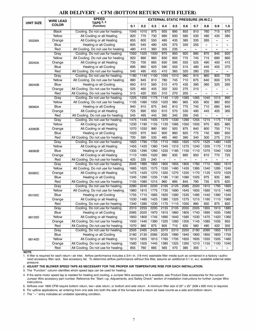
AIR DELIVERY -- CFM (BOTTOM RETURN WITH FILTER)
UNIT SIZE WIRE LEADCOLOR
SPEEDTAPS 2, 3(Function)
EXTERNAL STATIC PRESSURE (IN.W.C.)
0.1 0.2 0.3 0.4 0.5 0.6 0.7 0.8 0.9 1.0
30026A
Black Cooling. Do not use for heating. 1045 1010 975 935 895 855 810 760 715 670Yellow Alt Cooling or alt Heating 820 770 730 680 630 585 530 480 435 385Orange Alt Cooling or alt Heating 655 600 550 495 435 385 335 265 --- ---Blue Heating or alt Cooling 605 545 490 435 375 335 255 --- --- ---Red Alt Cooling. Do not use for heating. 480 415 360 305 235 --- --- --- --- ---
30040A
Gray Cooling. Do not use for heating. 1050 1025 1000 975 950 920 895 870 845 820Yellow Alt Cooling. Do not use for heating. 920 890 860 830 805 775 745 715 690 660Orange Alt Cooling or alt Heating 735 700 665 630 595 555 525 490 450 415Blue Heating or alt Cooling 695 660 625 590 555 515 480 445 405 370Red Alt Cooling. Do not use for heating. 540 495 455 410 365 320 280 235 --- ---
36040B
Gray Cooling. Do not use for heating. 1180 1140 1100 1055 1010 960 915 860 805 735Yellow Alt Cooling. Do not use for heating. 880 845 810 780 745 710 675 640 600 570Blue Heating or alt Cooling 650 610 560 515 470 435 395 360 325 265Orange Alt Cooling. Do not use for heating. 525 460 405 350 320 275 210 --- --- ---Red Alt Cooling. Do not use for heating. 515 420 350 310 270 205 --- --- --- ---
36060A
Gray Cooling. Do not use for heating. 1225 1200 1175 1145 1120 1095 1065 1040 1015 990Yellow Alt Cooling. Do not use for heating. 1105 1080 1050 1020 990 965 935 905 880 850Blue Heating or alt Cooling 940 910 875 845 810 775 745 710 680 645Orange Alt Cooling or alt Heating 725 690 650 610 570 530 490 445 405 365Red Alt Cooling. Do not use for heating. 545 495 445 395 345 295 245 --- --- ---
42060B
Gray Cooling. Do not use for heating. 1475 1445 1405 1370 1330 1290 1255 1215 1175 1140Yellow Alt Cooling or alt Heating 1230 1190 1155 1120 1085 1050 1005 970 925 885Orange Alt Cooling or alt Heating 1070 1030 990 950 920 875 840 800 755 715Blue Heating or alt Cooling 1020 975 940 900 860 820 775 740 690 650Red Alt Cooling. Do not use for heating. 700 590 535 485 460 390 340 300 275 210
48080B
Gray Cooling. Do not use for heating. 1820 1790 1755 1710 1665 1620 1570 1525 1480 1435Yellow Alt Cooling or alt Heating 1455 1420 1380 1345 1310 1275 1240 1205 1170 1135Blue Heating or alt Cooling 1335 1295 1260 1220 1185 1150 1110 1075 1040 1005Orange Alt Cooling or alt Heating 1110 1065 1020 980 935 895 850 810 770 725Red Alt Cooling. Do not use for heating. 425 335 240 --- --- --- --- --- --- ---
60080C
Gray Cooling. Do not use for heating. 2045 1995 1950 1900 1855 1805 1760 1710 1660 1615Yellow Alt Cooling. Do not use for heating. 1665 1625 1575 1530 1480 1435 1385 1340 1285 1240Orange Alt Cooling or alt Heating 1475 1420 1370 1320 1270 1220 1170 1125 1070 1025Blue Heating or alt Cooling 1345 1290 1235 1180 1130 1080 1025 975 935 885Red Alt Cooling. Do not use for heating. 1155 1080 1015 960 895 845 790 735 675 620
60100C
Gray Cooling. Do not use for heating. 2280 2240 2200 2165 2125 2085 2020 1910 1795 1665Yellow Alt Cooling. Do not use for heating. 1860 1815 1775 1730 1690 1645 1605 1560 1515 1465Blue Heating or alt Cooling 1755 1710 1665 1620 1580 1535 1485 1440 1390 1340Orange Alt Cooling or alt Heating 1530 1480 1425 1380 1325 1275 1215 1160 1110 1060Red Cooling. Do not use for heating. 1340 1285 1230 1170 1110 1050 990 930 875 820
66120D
Gray Cooling. Do not use for heating. 2310 2255 2205 2155 2105 2055 2005 1955 1910 1885Blue Heating or alt Cooling 2065 2020 1970 1915 1860 1805 1740 1690 1635 1580Yellow Alt Cooling or alt Heating 1850 1800 1745 1690 1640 1585 1530 1475 1420 1360Orange Alt Cooling. Do not use for heating. 1500 1440 1380 1320 1260 1205 1145 1085 1035 955Red Alt Cooling. Do not use for heating. 1070 960 875 805 710 630 560 490 420 355
66140D
Gray Cooling. Do not use for heating. 2505 2465 2425 2370 2310 2250 2180 2090 1955 1810Blue Heating or alt Cooling 2180 2130 2085 2035 1990 1945 1900 1850 1800 1755Yellow Alt Cooling or alt Heating 1910 1855 1810 1760 1705 1655 1605 1555 1505 1460Orange Alt Cooling. Do not use for heating. 1560 1505 1445 1380 1325 1265 1210 1155 1100 1040Red Alt Cooling. Do not use for heating. 855 760 665 565 470 385 305 --- --- ---
NOTE:1. A filter is required for each return ---air inlet. Airflow performance includes a 3/4---in. (19 mm) washable filter media such as contained in a factory---autho-rized accessory filter rack. See accessory list. To determine airflow performance without this filter, assume an additional 0.1 in. w.c. available external staticpressure.
2. ADJUST THE BLOWER SPEED TAPS AS NECESSARY FOR THE PROPER AIR TEMPERATURE RISE FOR EACH INSTALLATION.3. The “Function” column identifies which speed taps can be used for heating.
4. If the same motor speed tap is needed for heating and cooling, a Jumper Wire accessory kit is available, see Product Data accessories for the currentJumper Wire accessory part number. Reference the “Start ---up, Adjustments, and Safety Check” section of installation instructions for further Jumper Wireinstructions.
5. Airflows over 1800 CFM require bottom return, two---side return, or bottom and side return. A minimum filter size of 20” x 25” (508 x 635 mm) is required.6. For upflow applications, air entering from one side into both the side of the furnace and a return air base counts as a side and bottom return.7. The “---” entry indicates an unstable operating condition.

8
MAXIMUM ALLOWABLE EXPOSED VENT LENGTH IN UNCONDITIONED SPACE -- FT.
WinterDesignTemp° F
Unit Size26,000* BTUH
0” Insulation 3/8” Insulation 1/2” InsulationPipe Dia.In. 1½ 2 1½ 2 1½ 2
20 20 20 50 45 60 500 5 5 25 20 30 25---20 15 10 20 15---40 10 5 15 10
WinterDesignTemp ° F
Unit Size40,000* BTUH 60,000 BTUH
Uninsulated 3/8-in. Insulation 1/2-in. Insulation Uninsulated 3/8-in. Insulation 1/2-in. InsulationPipe Dia.in. 1 ½ 2 2 ½ 1 ½ 2 2 ½ 1 ½ 2 2 ½ 1 ½ 2 2 ½ 3 1 ½ 2 2 ½ 3 1 ½ 2 2 ½ 3
20 20 20 20 20 50 45 20 60 50 20 30 30 25 20 75 65 60 20 85 75 650 10 5 5 20 25 20 20 30 25 15 15 10 10 20 40 30 25 20 45 40 30-20 5 20 15 10 20 20 15 10 5 20 25 20 15 20 30 25 20-40 15 10 5 15 15 10 5 20 15 15 10 20 20 15 10
WinterDesignTemp° F
Unit Size80,000 BTUH
Uninsulated 3/8-in. Insulation 1/2-in. InsulationPipe Dia.in. 1 ½ 2 2 ½ 3 4 1 ½ 2 2 ½ 3 4 1 ½ 2 2 ½ 3 4
20 15 40 40 35 30 15 50 90 75 65 15 50 70 70 700 15 20 15 10 5 15 50 45 35 30 15 50 50 40 35-20 15 10 5 15 35 30 20 15 15 40 30 25 15-40 10 5 15 25 20 15 5 15 30 25 20 10
WinterDesignTemp ° F
Unit Size100,000 BTUH
Uninsulated 3/8-in. Insulation 1/2-in. InsulationPipe Dia.in. 2 2 ½ 3 4 2 2 ½ 3 4 2 2 ½ 3 4
20 20 50 40 35 20 80 95 80 20 80 105 900 20 20 15 10 20 55 45 35 20 65 55 45-20 15 10 5 20 35 30 20 20 45 35 25-40 10 5 20 25 20 10 20 30 25 15
WinterDesignTemp ° F
Unit Size120,000 BTUH 140,000* BTUH
Uninsulated 3/8-in. Insulation 1/2-in. Insulation Uninsulated 3/8-in. Insulation 1/2-in. InsulationPipe Dia.in. 2 ½ 3 4 2 ½ 3 4 2 ½ 3 4 2 ½ 3 4 2 ½ 3 4 2 ½ 3 4
20 10 50 40 10 75 95 10 75 105 5 55 50 5 65 105 5 65 1250 10 20 15 10 55 45 10 65 50 5 25 15 5 65 50 5 65 60---20 10 10 10 35 25 10 45 30 5 10 5 5 45 30 5 50 40---40 10 5 10 25 15 10 30 20 5 5 5 30 20 5 35 25
* Not all model families have these sizes

9
MAXIMUM ALLOWABLE EXPOSED VENT LENGTH IN UNCONDITIONED SPACE --METERS
WinterDesignTemp° C
Unit Size26,000* BTUH
0” Insulation 3/8” Insulation 1/2” InsulationPipe Dia.mm 38 51 38 51 38 51
---7 6.1 6.1 15.2 13.7 18.3 15.2---18 1.5 1.5 7.6 6.1 9.1 7.6---29 4.6 3.0 6.1 4.6---40 3.0 1.5 4.6 3.0
WinterDesignTemp° C
Unit Size40,000* BTUH 60,000 BTUH
Uninsulated 3/8-in. Insulation 1/2-in. Insulation Uninsulated 3/8-in. Insulation 1/2-in. InsulationPipe Dia.mm 38 51 64 38 51 64 38 51 64 38 51 64 76 38 51 64 76 38 51 64 76
---7 6.1 6.1 6.1 6.1 15.2 13.7 6.1 18.3 15.2 6.1 9.1 9.1 7.6 6.1 22.9 19.8 18.3 6.1 25.9 22.9 19.8---18 3.0 1.5 1.5 6.1 7.6 6.1 6.1 9.1 7.6 4.6 4.6 3.0 3.0 6.1 12.2 9.1 7.6 6.1 13.7 12.2 9.1---29 1.5 6.1 4.6 3.0 6.1 6.1 4.6 3.0 1.5 6.1 7.6 6.1 4.6 6.1 9.1 7.6 6.1---40 4.6 3.0 1.5 4.6 4.6 3.0 1.5 6.1 4.6 4.6 3.0 6.1 6.1 4.6 3.0
WinterDesignTemp° C
Unit Size80,000 BTUH
Uninsulated 3/8-in. Insulation 1/2-in. InsulationPipe Dia.mm 38 51 64 76 102 38 51 64 76 102 38 51 64 76 102
---7 4.6 12.2 12.2 10.7 9.1 4.6 15.2 27.4 22.9 19.8 4.6 15.2 21.3 21.3 21.3---18 4.6 6.1 4.6 3.0 1.5 4.6 15.2 13.7 10.7 9.1 4.6 15.2 15.2 12.2 10.7---29 4.6 3.0 1.5 4.6 10.7 9.1 6.1 4.6 4.6 12.2 9.1 7.6 4.6---40 3.0 1.5 4.6 7.6 6.1 4.6 1.5 4.6 9.1 7.6 6.1 3.0
WinterDesignTemp° C
Unit Size100,000 BTUH
Uninsulated 3/8-in. Insulation 1/2-in. InsulationPipe Dia.mm 51 64 76 102 51 64 76 102 51 64 76 102
---7 6.1 15.2 12.2 10.7 6.1 24.4 28.9 24.4 6.1 24.4 32.0 27.4---18 6.1 6.1 4.6 3.0 6.1 16.8 13.7 10.7 6.1 19.8 16.7 13.7---29 4.6 3.0 1.5 6.1 10.7 9.1 6.1 6.1 13.7 10.7 7.6---40 3.0 1.5 6.1 7.6 6.1 3.0 6.1 9.1 7.6 4.6
WinterDesignTemp° C
Unit Size120,000 BTUH 140,000 BTUH*
Uninsulated 3/8-in. Insulation 1/2-in. Insulation Uninsulated 3/8-in. Insulation 1/2-in. InsulationPipe Dia.mm 64 76 102 64 76 102 64 76 102 64 76 102 64 76 102 64 76 102
---7 3.0 15.2 12.2 3.0 22.9 28.9 3.0 22.9 32.0 1.5 16.7 15.2 1.5 19.8 32.0 1.5 19.8 38.1---18 3.0 6.1 4.6 3.0 16.8 13.7 3.0 19.8 15.2 1.5 7.6 4.6 1.5 19.8 15.2 1.5 19.8 18.3---29 3.0 3.0 3.0 10.7 7.6 3.0 13.7 9.1 1.5 3.0 1.5 1.5 13.7 9.1 1.5 15.2 12.2-40 3.0 1.5 3.0 7.6 4.6 3.0 9.1 6.1 1.5 1.5 1.5 9.1 6.1 1.5 35 7.6
* Not all model families have these sizes

10
MAXIMUM EQUIVALENT VENT LENGTH -- FT. (M)Table 1 – Maximum Equivalent Vent Length
NOTE: Maximum Equivalent Vent Length (MEVL) includes standard and concentric vent termination and does NOT include elbows.Use Table 2 - Deductions from Maximum Equivalent Vent Length to determine allowable vent length for each application.Unit Size 26,000 2 40,000 1 60,000 2 80,000 100,000 120,000 140,000
Altitude(feet)
Pipe Dia. (in) 1 ½ 2 1 ½ 2 2 ½ 1 ½ 2 2 ½ 3 1 ½ 2 2 ½ 3 4 2 2 ½ 3 4 2 ½ 3 4 2 ½ 3 40---2000 70 200 40 155 185
20100 175 200 15 55 130 175 200 20 80 175 200
1075 185 5 65 155
2001---3000 65 190 35 150 175 95 165 185
10
49125 165 185
15 75165 185 70 175
N/A
60140
3001---4000 60 175 30 135 160 16 90 155 175 115 155 175155
175 5 65 165 1204001---4500
55 160 25130 155
1585 150 170
44 110150 165
10
70 170
N/A
60160
50 1104501---5000 125 145 80 145 165 145 160
65150 165 45 100
5001---6000 50 145 20 120 130 75 140 155 41 100 135 150 140 155 155 35 806001---7000 45 135 15 110 120 13 70 130 145
N/A
3890
125 140 60 135 145 50 140 30 657001---8000 40 120
10100 110 10 65 120 135 36 120 125
N/A55 125 135 46 130 25 45
8001---9000 35 110 90 95 5 60 115 125 33 80 110 115 50 115 125 43 120 15 309001---10000 30 95 5 80 85 N/A 55 105 115 30 75 100 105 45 100 115 39 115 10 15
Maximum Equivalent Vent Length --- MetersUnit Size 26,000 2 40,000 1 60,000 2 80,000 100,000 120,000 140,000
Altitude(meters)
Pipe Dia.(mm) 38 51 38 51 64 38 51 64 76 38 51 64 76 102 51 64 76 102 64 76 102 64 76 102
0---610 21.3 60.9 12.1 47.2 56.36.0
30.4 53.3 60.9 4.5 16.7 39.6 53.3 60.9 6.0 24.3 53.3 60.93.0
22.8 56.3 1.5 19.8 47.2611---914 19.8 57.9 10.6 45.7 53.3 28.9 50.2 56.3
3.0
14.938.1 50.2 56.3
4.5 22.850.2 56.3 21.3 53.3
NA
18.242.6
915---1219 18.2 53.3 9.1 41.1 48.7 4.8 27.4 47.2 53.3 35.0 47.2 53.347.2
53.3 1.5 19.8 50.2 36.51220---1370
16.7 48.7 7.639.6 47.2
4.525.9 45.7 51.8
13.4 33.545.7 50.2
3.0
21.3 51.8
NA
18.248.7
15.2 33.51371---1524 38.1 44.1 24.3 44.1 50.2 44.1 48.7
19.845.7 50.2 13.7 30.4
1525---1829 15.2 44.1 6.0 36.5 39.6 22.8 42.6 47.2 12.4 30.4 41.1 45.7 42.6 47.2 47.2 10.6 24.31830---2134 13.7 41.1 4.5 33.5 36.5 3.9 21.3 39.6 44.1
NA
11.527.4
38.1 42.6 18.2 41.1 44.1 15.2 42.6 9.1 19.82135---2438 12.1 36.5
3.030.4 33.5 3.0 19.8 36.5 41.1 10.9 36.5 38.1
NA16.7 38.1 41.1 14.0 39.6 7.6 13.7
2439---2743 10.6 33.5 27.4 28.9 1.5 18.2 35.0 38.1 10.0 24.3 33.5 35.0 15.2 35.0 38.1 13.1 36.5 4.5 9.12744---3048 9.1 28.9 1.5 24.3 25.9 NA 16.7 32.0 35.0 9.1 22.8 30.4 32.0 13.7 30.4 35.0 11.8 35.0 3.0 4.5
NOTES:1. Inducer Outlet Restrictor disk (P/N 337683---401; 1.25---in. (32 mm) Dia.) shipped in the loose parts bag or available through Replacement Componentsrequired under 10---ft. (3 M) TEVL in all orientations. Required for installations from 0 --- 2000 (0 to 610 M) above sea level. Failure to use an outletrestrictor may result in flame disturbances or flame sense lock---out.
2. Inducer Outlet Restrictor disk (P/N 337683---401; 1.25---in. (32 mm) Dia.) shipped in the loose parts bag or available through Replacement Componentsrequired for no greater than 5---ft. (1.5 M) TEVL in downflow and horizontal orientations only. Required for installations from 0 --- 2000 (0 to 610 M) abovesea level.
Long Medium Mitered
Concentric
Standard 2-in., 3-in., or optional 4-in. termination.
ELBOW CONFIGURATIONS VENT TERMINAL CONFIGURATIONS
A13110
Table 2 – Deductions from Maximum Equivalent Vent Length -- Ft. (M)Pipe Diameter (in): 1-1/2 2 2-1/2 3 4Mitered 90º Elbow 8 (2.4) 8 (2.4) 8 (2.4) 8 (2.4) 8 (2.4)Medium Radius 90º Elbow 5 (1.5) 5 (1.5) 5 (1.5) 5 (1.5) 5 (1.5)Long Radius 90º Elbow 3 (0.9) 3 (0.9) 3 (0.9) 3 (0.9) 3 (0.9)Mitered 45º Elbow 4 (1.2) 4 (1.2) 4 (1.2) 4 (1.2) 4 (1.2)Medium Radius 45º Elbow 2.5 (0.8) 2.5 (0.8) 2.5 (0.8) 2.5 (0.8) 2.5 (0.8)Long Radius 45º Elbow 1.5 (0.5) 1.5 (0.5) 1.5 (0.5) 1.5 (0.5) 1.5 (0.5)Tee 16 (4.9) 16 (4.9) 16 (4.9) 16 (4.9) 16 (4.9)Concentric Vent Termination NA 0 (0.0) NA 0 (0.0) NAStandard Vent Termination 0 (0.0) 0 (0.0) 0 (0.0) 0 (0.0) 0 (0.0)NOTES:1. Use only the smallest diameter pipe possible for venting. Over ---sizing may cause flame disturbance or excessive vent terminal icing or freeze---up.2. NA --- Not allowed. Pressure switch will not close, or flame disturbance may result.3. Vent sizing for Canadian installations over 4500 ft. (1370 M) above sea level are subject to acceptance by the local authorities having jurisdiction.4. Size both the combustion air and vent pipe independently, then use the larger size for both pipes.5. Assume the two 45_ elbows equal one 90_ elbow. Wide radius elbows are desirable and may be required in some cases.6. Elbow and pipe sections within the furnace casing and at the vent termination should not be included in vent length or elbow count.7. The minimum pipe length is 5 ft. (2 M) linear feet (meters) for all applications.8. Use 3---in. (76 mm) diameter vent termination kit for installations requiring 4---in. (102 mm) diameter pipe.

11
Venting System Length CalculationsThe Total Equivalent Vent Length (TEVL) for EACH combustion air or vent pipe equals the length of the venting system, plus the equivalentlength of elbows used in the venting system from Table 2.
Standard vent terminations or factory accessory concentric vent terminations count for zero deduction.
See vent system manufacturer’s data for equivalent lengths of flexible vent pipe or other termination systems. DO NOT ASSUME that onefoot of flexible vent pipe equals one foot of straight PVC/ABS DWV vent pipe.
Compare the Total Equivalent Vent Length to the Maximum Equivalent Vent Lengths in Table 1.
Example 1A direct-vent 60,000 BTUH furnace installed at 2100 ft. (640M). Venting system includes FOR EACH PIPE:70 feet (22 M) of vent pipe, 65 feet (20 M) of combustion air inlet pipe, (3) 90º long-radius elbows, (2) 45º long-radius elbows, and a factoryaccessory concentric vent kit.
Can this application use 2” (50 mm ND) PVC/ABS DWV vent piping?
Measure the required linear length of air inlet andvent pipe; insert the longest of the two here
70 ft.(22 M)
Use length of the longer of the ventor air inlet piping system
Add equiv length of (3) 90º long-radius elbows(use the highest number of elbows for either thevent or inlet pipe)
3 x 3 ft.(0.9 M) = 9 ft.
(2.7 M) From Table 2
Add equiv length of (2) 45º long-radius elbows(use the highest number of elbows for either thevent or inlet pipe)
2 x 1.5 ft.(0.5 M) = 3 ft.
(0.9 M) From Table 2
Add equiv length of factory concentric vent term 0 ft. From Table 2
Add correction for flexible vent pipe, if any 0 ft. From Vent Manufacturer’sinstructions; zero for PVC/ABS DWV
Total Equivalent Vent Length (TEVL) 82 ft.(25 M) Add all of the above lines
Maximum Equivalent Vent Length (MEVL) 95 ft.(29 M) For 2” pipe from Table 1
Is TEVL less than MEVL? YES Therefore, 2” pipe MAY be used
Example 2A direct-vent 60,000 BTUH furnace installed at 2100 ft. (640M). Venting system includes FOR EACH PIPE:100 feet (30 M) of vent pipe, 95 feet (29 M) of combustion air inlet pipe, (3) 90º long-radius elbows, and a polypropylene concentric vent kit.Also includes 20 feet (6.1 M) of flexible polypropylene vent pipe, included within the 100 feet (30 M) of vent pipe.
VERIFY FROM POLYPROPYLENE VENT MANUFACTURER’S INSTRUCTIONS for the multiplier correction for flexible vent pipe.
Can this application use 60mm o.d. (2”) polypropylene vent piping? If not, what size piping can be used?
Measure the required linear length of RIGID air inlet and vent pipe; insertthe longest of the two here: 100 ft. Of rigid pipe --- 20 ft. Of flexible pipe
= 80 ft.(24 M)
Use length of the longer of the ventor air inlet piping system
Add equiv length of (3) 90º long-radius elbows(use the highest number of elbows for either thevent or inlet pipe)
3 x 5 ft.(1.5 M) = 15 ft.
(4.6 M)
Example from polypropylene ventmanufacturer’s instructions, Verify from vent
manufacturer’s instructions.
Add equiv length of 45º long-radius elbows(use the highest number of elbows for either thevent or inlet pipe)
0 x = 0 ft.(0 M)
Add equiv length of factory concentric vent term 9 x 3.3 ft(0.9 M) = 30 ft.
(9 M)
Add correction for flexible vent pipe, if any 2* x 20 ft.(6.1 M) = 40 ft.
(12.2 M)* VERIFY FROM VENT MANUFACTURER’S INSTRUCTIONS; For example only, assume 1 meter of flexible 60mm (2”) or 80mm (3”)polypropylene pipe equals 2.0 meters (6.5 ft.) of PVC/ABS pipe.
Total Equivalent Vent Length (TEVL) 165 ft.(50 M) Add all of the above lines
Maximum Equivalent Vent Length (MEVL) 95 ft.(29 M) For 2” pipe from Table 2
Is TEVL less than MEVL? NO Therefore, 60mm (2”) pipe may NOT beused; try 80mm (3”)
Maximum Equivalent Vent Length (MEVL) 185 ft.(57 M) For 3” pipe from Table 2
Is TEVL less than MEVL? YES Therefore, 80mm (3”) pipe MAY be used

12
RETURN AIR TEMPERATUREThis furnace is designed for continuous return--air minimum temperature of 60_F (15_C) db or intermittent operation down to 55_F (13_C)db such as when used with a night setback thermometer. Return--air temperature must not exceed 80_F (27_C) db. Failure to follow thesereturn air limits may affect reliability of heat exchangers, motors and controls.
60
80 / 27˚C
/ 16˚C
SUPPLY AIR
A10490
MINIMUM CLEARANCES TO COMBUSTIBLE MATERIALSPOSITION CLEARANCE
Rear 0 (0 mm)Front (Combustion air openings in furnace and in structure) 1 in. (25 mm)
Required for service** 24 in. (610 mm)*All Sides of Supply Plenum** 1 in. (25 mm)
Sides 0 (0 mm)Vent 0 (0 mm)
Top of Furnace 1 in. (25 mm)* Recommended**Consult your local building codes
COMBUSTION--AIR PIPE FOR NON--DIRECT (1--PIPE) VENT APPLICATION
FIELD-SUPPLIED2-IN. (51 mm) DIA.PVC PIPE
FIELD-SUPPLIED2-IN. (51 mm) DIA.MITERED RADIUSPVC 90° ELBOW
12” (300 mm) MINIMUMA12376
NOTE: See Installation Instructions for specific venting configurations.
13
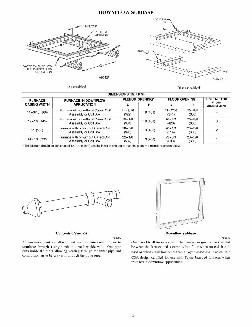
DOWNFLOW SUBBASELOCATING
TAB
LOCATINGTAB
1 2 3 4
4 3 2 1
B
D
C
A
1 1/4-IN. TYP
PLENUMOPENING
FACTORY-SUPPLIEDFIELD-INSTALLED
INSULATION
Assembled Disassembled
A97427 A88207
DIMENSIONS (IN. / MM)
FURNACECASING WIDTH
FURNACE IN DOWNFLOWAPPLICATION
PLENUM OPENING* FLOOR OPENING HOLE NO. FORWIDTH
ADJUSTMENTA B C D
14---3/16 (360) Furnace with or without Cased CoilAssembly or Coil Box
11---3/16(322) 19 (483) 13---7/16
(341)20---5/8(600) 4
17---1/2 (445) Furnace with or without Cased CoilAssembly or Coil Box
15---1/8(384) 19 (483) 16---3/4
(426)20---5/8(600) 3
21 (533) Furnace with or without Cased CoilAssembly or Coil Box
18---5/8(396) 19 (483) 20---1/4
(514)20---5/8(600) 2
24---1/2 (622) Furnace with or without Cased CoilAssembly or Coil Box
22---1/8(562) 19 (483) 23---3/4
(603)20---5/8(600) 1
*The plenum should be constructed 1/4---in. (6 mm) smaller in width and depth than the plenum dimensions shown above.
Concentric Vent KitA93086
A concentric vent kit allows vent and combustion--air pipes toterminate through a single exit in a roof or side wall. One piperuns inside the other allowing venting through the inner pipe andcombustion air to be drawn in through the outer pipe.
Downflow SubbaseA88202
One base fits all furnace sizes. The base is designed to be installedbetween the furnace and a combustible floor when no coil box is
used or when a coil box other than a Payne cased coil is used. It is
CSA design certified for use with Payne branded furnaces wheninstalled in downflow applications.

14
MEDIA FILTER CABINET (OPTIONAL ACCESSORY)
Media FilterCabinet A B
16" (406mm)20" (508mm)24" (610mm)
17" (432mm)
Furnace Side
Centerline Screw Slots
23-3/4”
23-3/8”
23-5/8"
534
Duct Side
Opening
Opening with Flanges Bent
24-1/4”
25-5/8"
B O
pening
A
"
(600mm)
(594mm)
(603mm)
(146mm)
(651mm)
(616mm)
23-1/8”(588mm)
16" (406mm)20" (508mm)24" (610mm)
21" (533mm)25" (635mm)
NOTE: Media cabinet is matched to the bottom opening on furnace. May also be used for side return.
A12428
TYPICAL WIRING SCHEMATIC
115-V FIELD-SUPPLIED
DISCONNECT
AUXILIARYJ-BOX
24-VTERMINAL
BLOCK
THREE-WIREHEATING-ONLY
FIVE WIRE
NOTE 1
NOTE 2FIELD-SUPPLIEDDISCONNECT
CONDENSINGUNIT
TWOWIRE
FURNACE
CONTROL
R
G
COM
W C R G Y
GND
GND
FIELD 24-V WIRINGFIELD 115-, 208/230-, 460-V WIRINGFACTORY 24-V WIRINGFACTORY 115-V WIRING
208/230- OR460-VTHREEPHASE
208/230-VSINGLEPHASE
BLOWER DOOR SWITCH
WHT
BLK
WHT
BLK
NOTES: Connect Y-terminal in furnace as shown for proper blower operation.Some thermostats require a "C" terminal connection as shown.If any of the original wire, as supplied, must be replaced, usesame type or equivalent wire.
W
Y
GND
THERMOSTATTERMINALS
1.2.3.
A11387

15
DIMENSIONAL DRAWING
A180203
FURNACE SIZEA B C D SHIP WT.
LB (KG)CABINET WIDTH OUTLET WIDTH BOTTOM INLET WIDTH AIR INTAKE30026A 14---3/16 (361) 12---1/2 (319) 12---9/16 (322) 7---1/8 (181) 118.0 (53.5)30040A 14---3/16 (361) 12---1/2 (319) 12---9/16 (322) 7---1/8 (181) 120 (54.4)36040B 17---1/2 (445) 15---7/8 (403) 16 (406) 8---3/4 (222) 126.5 (57.4)36060A 14---3/16 (361) 12---1/2 (319) 12---9/16 (322) 7---1/8 (181) 129 (58.5)42060B 17---1/2 (445) 15---7/8 (403) 16 (406) 8---3/4 (222) 138.5 (62.8)48080B 17---1/2 (445) 15---7/8 (403) 16 (406) 8---3/4 (222) 146.5 (66.5)60080C 21 (533) 19---3/8 (492) 19---1/2 (495) 10---1/2 (267) 154.5 (70.1)60100C 21 (533) 19---3/8 (492) 19---1/2 (495) 10---1/2 (267) 164.5 (74.6)66120D 24---1/2 (622) 22---7/8 (581) 23 (584) 12---1/4 (311) 179.5 (81.4)66140D 24---1/2 (622) 22---7/8 (581) 23 (584) 12---1/4 (311) 189 (85.7)

16
GUIDE SPECIFICATIONSGeneralSystem DescriptionFurnish a ______________________ 4--way multipoise gas--firedcondensing furnace for use with natural gas or propane (factory--authorized conversion kit required for propane).
Quality AssuranceUnit will be designed, tested and constructed to the current ANSI Z21.47/CSA 2.3 design standard for gas--fired central furnaces.
Unit will be third party certified by CSA to the current ANSI Z21.47/CSA 2.3 design standard for gas--fired central furnaces. Unitwill carry the CSA Blue StarR and Blue FlameR labels. Unitefficiency testing will be performed per the current DOE testprocedure as listed in the Federal Register.
Unit will be certified for capacity and efficiency and listed in thelatest AHRI Consumer’s Directory of Certified Efficiency Ratings.
Unit will carry the current Federal Trade Commission EnergyGuide efficiency label.
Delivery, Storage, and HandlingUnit will be shipped as single package only and is stored andhandled per unit manufacturer’s recommendations.
Warranty (for inclusion by specifying engineer)U.S. and Canada only. Warranty certificate available upon request.
EquipmentBlower Wheel and ECM Blower Motor
Galvanized blower wheel shall be centrifugal type, statically anddynamically balanced. Blower motor of ECM type shall bepermanently lubricated with sealed ball bearings, of _______hp,and have multiple speeds from 600--1200 RPM operating onlywhen 24--VAC motor inputs are provided. Blower motor shall bedirect drive and soft mounted to the blower housing to reducevibration transmission.
Filters
Furnace shall have reusable--type filters. Filter shall be ______ in.(mm) X ________ in. (mm). An accessory highly efficient MediaFilter is available as an option. _____________ Media Filter.
Casing
Casing shall be of .030 in. thickness minimum, pre--painted steel.
Draft Inducer Motor
Draft inducer motor shall be single--speed PSC design.
Primary Heat Exchangers
Primary heat exchangers shall be 3--Pass corrosion--resistantaluminized steel of fold--and--crimp sectional design and appliedoperating under negative pressure.
Secondary Heat Exchangers
Secondary heat exchangers shall be of a stainless steelflow--through of fin--and--tube design and applied operating undernegative pressure.
Controls
Controls shall include a micro--processor--based integratedelectronic control board with at least 16 service troubleshootingcodes displayed via diagnostic flashing LED light on the control, aself--test feature that checks all major functions of the furnace, anda replaceable automotive--type circuit protection fuse. Multipleoperational settings available, including blower speeds for heatingand cooling.
Operating CharacteristicsHeating capacity shall be _________________ Btuh input;______________ Btuh output capacity.
Fuel Gas Efficiency shall be __________AFUE.
Air delivery shall be ________________ cfm minimum at 0.50 in.W.C. external static pressure.
Dimensions shall be: depth_________in. (mm); width__________in. (mm); height___________in. (mm) (casing only).Height shall be_________in. (mm) with A/C coil and_________________in. (mm) overall with plenum.
Electrical RequirementsElectrical supply shall be 115 volts, 60 Hz, single--phase (nominal).Minimum wire size shall be ________AWG; maximum fuse sizeof HACR--type designated circuit breaker shall be _________amps.
Special FeaturesRefer to section of the product data identifying accessories anddescriptions for specific features and available enhancements.
E2019 Payne Heating & Cooling Systems D 7310 W. Morris St. D Indianapolis, IN 46231 Edition Date: 05/19
Manufacturer reserves the right to change, at any time, specifications and designs without notice and without obligations.
Catalog No: SS---PG95ESAA---01Replaces: NEW