Embed Size (px)
Citation preview

560560560560560 Principles of Power System
is I1 amperes. Then the tower *rises to a potential V t given by ;Vt = I1R1
Since V t (= I1R1) is the approximate voltage between tower and line conductor, this is also thevoltage that will appear across the string of insulators. If the value of V t is less than that required tocause insulator flashover, no trouble results. On the other hand, if V t is excessive, the insulatorflashover may occur. Since the value of Vt depends upon tower-footing resistance R1, the value of thisresistance must be kept as low as possible to avoid insulator flashover.
Advantages(i) It provides considerable protection against direct lightning strokes on transmission lines.
(ii) A grounding wire provides damping effect on any disturbance travelling along the line as itacts as a short-circuited secondary.
(iii) It provides a certain amount of electrostatic shielding against external fields. Thus itreduces the voltages induced in the line conductors due to the discharge of a neighbouringcloud.
Disadvantages(i) It requires additional cost.
(ii) There is a possibility of its breaking and falling across the line conductors, thereby causinga short-circuit fault. This objection has been greatly eliminated by using galvanised strandedsteel conductors as ground wires. This provides sufficient strength to the ground wires.
24.1124.1124.1124.1124.11 Lightning Arr Lightning Arr Lightning Arr Lightning Arr Lightning Arrestersestersestersestersesters
The earthing screen and ground wires can well protect the electrical system against direct lightningstrokes but they fail to provide protection against travelling waves which may reach the terminalapparatus. The lightning arresters or surge diverters provide protection against such surges.
A lightning arrester or a surge diverter is a protective device which conducts the high voltagesurges on the power system to the ground.
* As a numerical illustration, if I1 = 50 kA and R1 = 50 Ω, then V t = 50 × 103 × 50 = 2500 kV. However, ifR1 = 10 Ω, then V t = 50 × 103 × 10 = 500 kV. Clearly, lesser the tower-footing resistance, smaller thepotential to which the tower rises.
Protection Against Overvoltages 561561561561561
* The characteristic is drawn between the voltage across the resistance and current through it.
** In actual practice, it may conduct current to ground even at normal supply due to capacitive effects. As theresistance R offers high resistance to normal votlage, this current is extremely small.
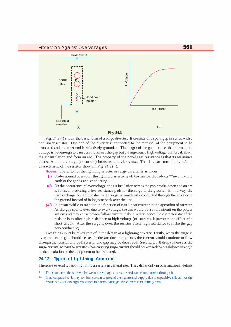
Fig. 24.8 (i) shows the basic form of a surge diverter. It consists of a spark gap in series with anon-linear resistor. One end of the diverter is connected to the terminal of the equipment to beprotected and the other end is effectively grounded. The length of the gap is so set that normal linevoltage is not enough to cause an arc across the gap but a dangerously high voltage will break downthe air insulation and form an arc. The property of the non-linear resistance is that its resistancedecreases as the voltage (or current) increases and vice-versa. This is clear from the *volt/ampcharacteristic of the resistor shown in Fig. 24.8 (ii).
Action. The action of the lightning arrester or surge diverter is as under :(i) Under normal operation, the lightning arrester is off the line i.e. it conducts **no current to
earth or the gap is non-conducting.(ii) On the occurrence of overvoltage, the air insulation across the gap breaks down and an arc
is formed, providing a low resistance path for the surge to the ground. In this way, theexcess charge on the line due to the surge is harmlessly conducted through the arrester tothe ground instead of being sent back over the line.
(iii) It is worthwhile to mention the function of non-linear resistor in the operation of arrester.As the gap sparks over due to overvoltage, the arc would be a short-circuit on the powersystem and may cause power-follow current in the arrester. Since the characteristic of theresistor is to offer high resistance to high voltage (or current), it prevents the effect of ashort-circuit. After the surge is over, the resistor offers high resistance to make the gapnon-conducting.
Two things must be taken care of in the design of a lightning arrester. Firstly, when the surge isover, the arc in gap should cease. If the arc does not go out, the current would continue to flowthrough the resistor and both resistor and gap may be destroyed. Secondly, I R drop (where I is thesurge current) across the arrester when carrying surge current should not exceed the breakdown strengthof the insulation of the equipment to be protected.
24.1224.1224.1224.1224.12 T T T T Types of Lightning Arrypes of Lightning Arrypes of Lightning Arrypes of Lightning Arrypes of Lightning Arrestersestersestersestersesters
There are several types of lightning arresters in general use. They differ only in constructional details
562562562562562 Principles of Power System
but operate on the same principle viz. providing low resistance path for the surges to the ground. Weshall discuss the following types of lightning arresters :
1. Rod gap arrester 2. Horn gap arrester3. Multigap arrester 4. Expulsion type lightning arrester
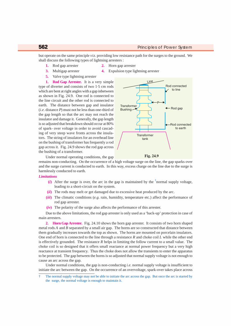
5. Valve type lightning arrester1. Rod Gap Arrester. It is a very simple
type of diverter and consists of two 1·5 cm rodswhich are bent at right angles with a gap inbetweenas shown in Fig. 24.9. One rod is connected tothe line circuit and the other rod is connected toearth. The distance between gap and insulator(i.e. distance P) must not be less than one-third ofthe gap length so that the arc may not reach theinsulator and damage it. Generally, the gap lengthis so adjusted that breakdown should occur at 80%of spark- over voltage in order to avoid cascad-ing of very steep wave fronts across the insula-tors. The string of insulators for an overhead lineon the bushing of transformer has frequently a rodgap across it. Fig. 24.9 shows the rod gap acrossthe bushing of a transformer.
Under normal operating conditions, the gapremains non-conducting. On the occurrence of a high voltage surge on the line, the gap sparks overand the surge current is conducted to earth. In this way, excess charge on the line due to the surge isharmlessly conducted to earth.
Limitations(i) After the surge is over, the arc in the gap is maintained by the †normal supply voltage,
leading to a short-circuit on the system.(ii) The rods may melt or get damaged due to excessive heat produced by the arc.
(iii) The climatic conditions (e.g. rain, humidity, temperature etc.) affect the performance ofrod gap arrester.
(iv) The polarity of the surge also affects the performance of this arrester.
Due to the above limitations, the rod gap arrester is only used as a ‘back-up’ protection in case ofmain arresters.
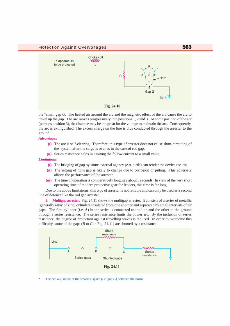
2. Horn Gap Arrester. Fig. 24.10 shows the horn gap arrester. It consists of two horn shapedmetal rods A and B separated by a small air gap. The horns are so constructed that distance betweenthem gradually increases towards the top as shown. The horns are mounted on porcelain insulators.One end of horn is connected to the line through a resistance R and choke coil L while the other endis effectively grounded. The resistance R helps in limiting the follow current to a small value. Thechoke coil is so designed that it offers small reactance at normal power frequency but a very highreactance at transient frequency. Thus the choke does not allow the transients to enter the apparatusto be protected. The gap between the horns is so adjusted that normal supply voltage is not enough tocause an arc across the gap.
Under normal conditions, the gap is non-conducting i.e. normal supply voltage is insufficient toinitiate the arc between the gap. On the occurrence of an overvoltage, spark-over takes place across
† The normal supply voltage may not be able to initiate the arc across the gap. But once the arc is started bythe surge, the normal voltage is enough to maintain it.
Protection Against Overvoltages 563563563563563
the *small gap G. The heated air around the arc and the magnetic effect of the arc cause the arc totravel up the gap. The arc moves progressively into positions 1, 2 and 3. At some position of the arc(perhaps position 3), the distance may be too great for the voltage to maintain the arc. Consequently,the arc is extinguished. The excess charge on the line is thus conducted through the arrester to theground.Advantages
(i) The arc is self-clearing. Therefore, this type of arrester does not cause short-circuiting ofthe system after the surge is over as in the case of rod gap.
(ii) Series resistance helps in limiting the follow current to a small value.Limitations
(i) The bridging of gap by some external agency (e.g. birds) can render the device useless.(ii) The setting of horn gap is likely to change due to corrosion or pitting. This adversely
affects the performance of the arrester.(iii) The time of operation is comparatively long, say about 3 seconds. In view of the very short
operating time of modern protective gear for feeders, this time is far long.
Due to the above limitations, this type of arrester is not reliable and can only be used as a secondline of defence like the rod gap arrester.
3. Multigap arrester. Fig. 24.11 shows the multigap arrester. It consists of a series of metallic(generally alloy of zinc) cylinders insulated from one another and separated by small intervals of airgaps. The first cylinder (i.e. A ) in the series is connected to the line and the other to the groundthrough a series resistance. The series resistance limits the power arc. By the inclusion of seriesresistance, the degree of protection against travelling waves is reduced. In order to overcome thisdifficulty, some of the gaps (B to C in Fig. 24.11) are shunted by a resistance.
* The arc will occur at the smallest space (i.e. gap G) between the horns.

564564564564564 Principles of Power System
Under normal conditions, the point B is at earth potential and the normal supply voltage is unableto break down the series gaps. On the occurrence of an overvoltage, the breakdown of series gaps Ato B occurs. The heavy current after breakdown will choose the straight - through path to earth via theshunted gaps B and C, instead of the alternative path through the shunt resistance. When the surge isover, the arcs B to C go out and any power current following the surge is limited by the two resistances(shunt resistance and series resistance) which are now in series. The current is too small to maintainthe arcs in the gaps A to B and normal conditions are restored. Such arresters can be employed wheresystem voltage does not exceed 33 kV.
4. Expulsion type arrester. This type of arrester is also called ‘protector tube’ and is com-monly used on system operating at voltages upto 33 kV. Fig. 24.12 (i) shows the essential parts of anexpulsion type lightning arrester. It essentially consists of a rod gap A A′ in series with a second gapenclosed within the fibre tube. The gap in the fibre tube is formed by two electrodes. The upperelectrode is connected to rod gap and the lower electrode to the earth. One expulsion arrester isplaced under each line conductor. Fig. 24.12 (ii) shows the installation of expulsion arrester on anoverhead line.
On the occurrence of an overvoltage on the line, the series gap A A′ is spanned and an arc isstruck between the electrodes in the tube. The heat of the arc vaporises some of the fibre of tubewalls, resulting in the production of a neutral gas*. In an extremely short time, the gas builds up highpressure and is expelled through the lower electrode which is hollow. As the gas leaves the tubeviolently, it carries away ionised air around the arc. This de-ionising effect is generally so strong thatarc goes out at a current zero and will not be re-established.
Advantages(i) They are not very expensive.
(ii) They are improved form of rod gap arresters as they block the flow of power frequencyfollow currents.
(iii) They can be easily installed.
* The gas evolved is an un-ionised mixture of water vapour and decomposition products of the fibre.

Protection Against Overvoltages 565565565565565Limitations
(i) An expulsion type arrester can perform only limited number of operations as during eachoperation some of the fibre material is used up.
(ii) This type of arrester cannot be mounted in an enclosed equipment due to the discharge ofgases during operation.
(iii) Due to the poor volt/amp characteristic of the arrester, it is not suitable for the protection ofexpensive equipment.
5. Valve type arrester. Valve type arresters incorporate non-linear resistors and are exten-sively used on systems operating at high voltages. Fig. 24.13 (i) shows the various parts of a valvetype arrester. It consists of two assemblies (i) series spark gaps and (ii) non-linear resistor discs(made of material such as thyrite or metrosil) in series. The non-linear elements are connected inseries with the spark gaps. Both the assemblies are accommodated in tight porcelain container.
(i) The spark gap is a multiple assembly consisting of a number of identical spark gaps inseries. Each gap consists of two electrodes with a fixed gap spacing. The voltage distribu-tion across the gaps is linearised by means of additional resistance elements (called gradingresistors) across the gaps. The spacing of the series gaps is such that it will withstand thenormal circuit voltage. However, an overvoltage will cause the gap to breakdown, causingthe surge current to ground via the non-linear resistors.
(ii) The non-linear resistor discs are made of an inorganic compound such as Thyrite or Metrosil.These discs are connected in series. The non-linear resistors have the property of offeringa high resistance to current flow when normal system voltage is applied, but a low resis-tance to the flow of high-surge currents. In other words, the resistance of these non-linearelements decreases with the increase in current through them and vice-versa.
Working. Under normal conditions, the normal system voltage is insufficient to cause the break-down of air gap assembly. On the occurrence of an overvoltage, the breakdown of the series sparkgap takes place and the surge current is conducted to earth via the non-linear resistors. Since themagnitude of surge current is very large, the non-linear elements will offer a very low resistance to the
566 Principles of Power System
passage of surge. The result is that the surge will rapidly go to earth instead of being sent back overthe line. When the surge is over, the non-linear resistors assume high resistance to stop the flow ofcurrent.Advantages
(i) They provide very effective protection (especially for transformers and cables) againstsurges.
(ii) They operate very rapidly taking less than a second.(iii) The *impulse ratio is practically unity.
Limitations(i) They **may fail to check the surges of very steep wave front from reaching the terminal
apparatus. This calls for additional steps to check steep-fronted waves.(ii) Their performance is adversely affected by the entry of moisture into the enclosure. This
necessitates effective sealing of the enclosure at all times.
Applications. According to their application, the valve type arresters are classified as (i) stationtype and (ii) line type. The station type arresters are generally used for the protection of importantequipment in power stations operating on voltages upto 220 kV or higher. The line type arresters arealso used for stations handling voltages upto 66 kV.
24.1324.1324.1324.1324.13 Sur Sur Sur Sur Surge ge ge ge ge AbsorberAbsorberAbsorberAbsorberAbsorber
The travelling waves set up on the transmission linesby the surges may reach the terminals apparatus andcause damage to it. The amount of damage caused notonly depends upon the amplitude of the surge but alsoupon the steepness of its wave front. The steeper thewave front of the surge, the more the damage causedto the equipment. In order to reduce the steepness ofthe wave front of a surge, we generally use surge ab-sorber.
A surge absorber is a protective device whichreduces the steepness of wave front of a surge by ab-sorbing surge energy.
Although both surge diverter and surge absorbereliminate the surge, the manner in which it is done isdifferent in the two devices. The surge diverter divertsthe surge to earth but the surge absorber absorbs thesurge energy. A few cases of surge absorption are dis-cussed below :
(i) A condenser connected between the line and earth can act as a surge absorber. Fig. 24.14shows how a capacitor acts as surge absorber to protect the transformer winding. Since thereactance of a condenser is inversely proportional to frequency, it will be low at high fre-quency and high at low frequency. Since the surges are of high frequency, the ***capacitor
* Impulse ratio = Breakdown voltage under surge conditionsBreakdown voltage under low frequency conditions
** The normal strokes on transmission lines after travelling along the line are considerably attenuated so thatthey are well within the reach of protection afforded by such arresters.
*** A pure capacitor, however, cannot dissipate the energy in the wave front of a travelling wave or in a highfrequency discharge. It merely reflects the wave energy away from the equipment to be protected and theenergy is dissipated in the line resistance and earth resistance.
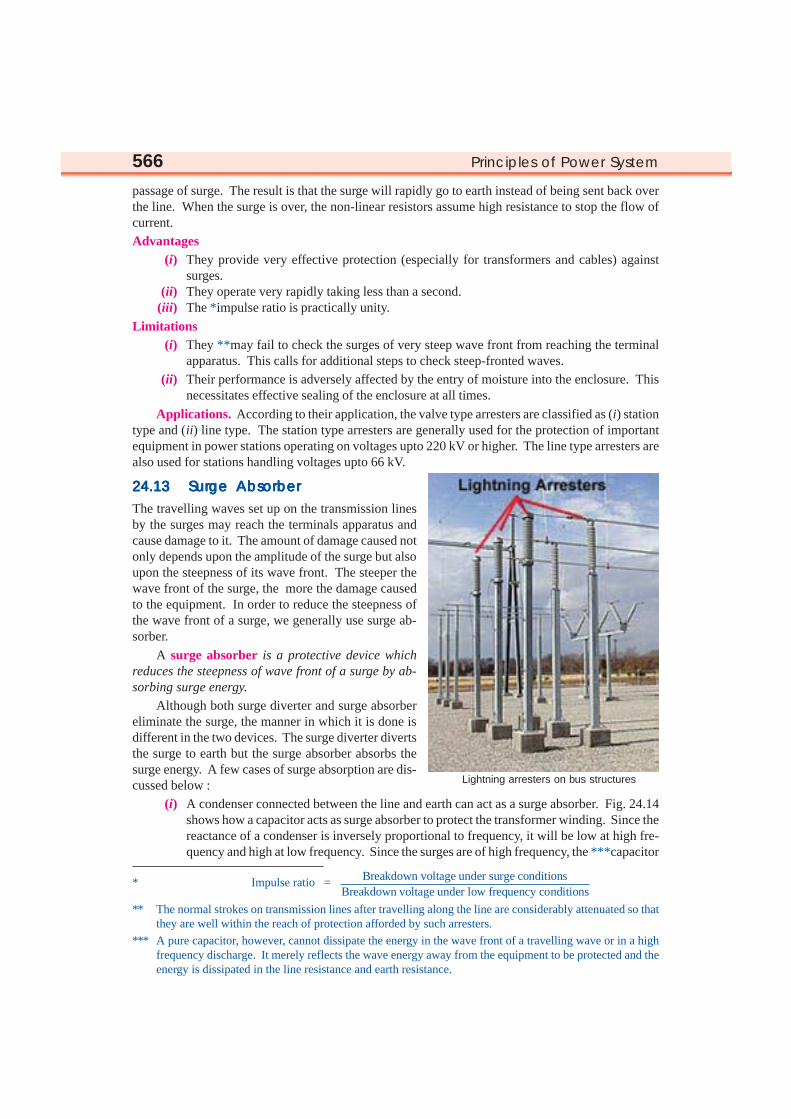
Lightning arresters on bus structures

Protection Against Overvoltages 567567567567567
acts as a short circuit and passes them directly to earth. However, for power frequency, thereactance of the capacitor is very high and practically no current flows to the ground.
(ii) Another type of surge absorber consists of a parallel combination of choke and resistanceconnected in series with the line as shown in Fig. 24.15. The choke offers high reactance tosurge frequencies (XL = 2 π f L). The surges are, therefore, forcedto flow through the resistance R where they are dissipated.
(iii) Fig. 24.16 shows the another type of surge absorber. It is calledFerranti surge absorber. It consists of an air cored inductor con-nected in series with the line. The inductor is surrounded by butinsulated from an earthed metallic sheet called dissipator. This ar-rangement is equivalent to a transformer with short-circuited sec-ondary. The inductor forms the primary whereas the dissipator formsthe short-circuited secondary. The energy of the surge is used up in the form of heat gener-ated in the dissipator due to transformer action. This type of surge absorber is mainly usedfor the protection of transformers.
Fig. 24.17 (i) shows the schematic diagram of 66 kV Ferranti surge absorber while Fig. 24.17 (ii)shows its equivalent circuit.
SELF - TESTSELF - TESTSELF - TESTSELF - TESTSELF - TEST
1. Fill in the blanks by inserting appropriate words/figures :(i) The most severe surges on the line are produced by ...............
(ii) Lightning produces a ............... fronted wave.(iii) Transients on the power system due to current chopping are taken care of by ...............(iv) Arcing ground can be prevented by ...............(v) The lightning currents range from 10 kA to about ............... kA.
(vi) For successful working of ground wire, the footing resistance of tower should be ...............

568568568568568 Principles of Power System
(vii) A surge diverter should be located ............... to the apparatus to be protected.2. Fill in the blanks by picking correct words/figures from brackets :
(i) A 1/50 µs surge is ............... harmful than 3/50 µs surge. Assume the same peak value.(more, less)
(ii) The ............... lightning strokes are very rare on the power system. (direct, indirect)(iii) Most of the lightning strokes are due to ............... charged clouds. (negatively, positively)(iv) The stroke A will always occur on ............... (tallest object, earth)(v) ............... cannot protect the equipment from the travelling waves reaching the equipment.
(ground wires, lightning arrester)(vi) In sub-stations, the most commonly used type of arrester is ............... arrester.
(Thyrite, horn gap, rod gap)(vii) Surge absorbers are used to ............... the steepness of wave front of the surge. (reduce, increase)
ANSWERS TO SELF-TESTANSWERS TO SELF-TESTANSWERS TO SELF-TESTANSWERS TO SELF-TESTANSWERS TO SELF-TEST
1. (i) lightning (ii) steep (iii) resistance switching (iv) earthing the neutral (v) 90 (vi) low (vii) close
2. (i) more (ii) direct (iii) negatively (iv) tallest object (v) ground wires (vi) thyrite (vii) reduce
CHAPTER REVIEW TOPICSCHAPTER REVIEW TOPICSCHAPTER REVIEW TOPICSCHAPTER REVIEW TOPICSCHAPTER REVIEW TOPICS
1. What is a voltage surge ? Draw a typical lightning voltage surge.2. Discuss the causes of overvoltages.3. What is lightning ? Describe the mechanism of lightning discharge.4. Describe the various types of lightning stroke.5. What are the harmful effects of lightning ?6. How do earthing screen and ground wires provide protection against direct lightning strokes ?7. What is a surge diverter ? What is the basic principle of operation of a surge diverter ?8. Write short notes on the following surge diverters :
(i) Rod gap diverter(ii) Horn gap diverter
(iii) Expulsion type diverter(iv) Multigap diverter
9. Discuss the construction, principle and working of a valve type arrester.10. What is a surge absorber ? Write a short note on Ferranti surge absorber.
DISCUSSION QUESTIONSDISCUSSION QUESTIONSDISCUSSION QUESTIONSDISCUSSION QUESTIONSDISCUSSION QUESTIONS
1. Why are steep fronted surges more dangerous to power system equipment ?2. Why is lightning accompanied by a thunder ?3. Is the name lightning arrester appropriate ?4. Why are surge diverters located very close to the equipment to be protected ?5. Where will you use a surge absorber ?