Embed Size (px)
Citation preview

ENGLISH - ESPAÑOL
Automatic ScrubberFregadora Automática
5500/5520
Operator and Parts ManualManual del Operador y Piezas
607551Rev. 01 (08-01)
����������
�� ���–� ��
�� ��–� ������
�� ��–� ��
�� ��–� ������
FAX: 1–800–678–4240 CUSTOMER SERVICE: 1–800-982–7658
TENNANT COMPANY Commercial Products12875 RANSOM STREET HOLLAND MI 49424 U.S.A.

OPERATION
2 Tennant 5500/5520 (08–01)
This manual is furnished with each new model. Itprovides necessary operation and maintenanceinstructions and an illustrated parts list.
Read this manual completely and understand themachine before operating or servicing it.
When ordering replacement parts, use the parts listsection in this manual. Before ordering parts orsupplies, be sure to have your machine model numberand serial number available. Parts and supplies maybe ordered by phone or mail from any authorizedService Center or Distributor.
This machine will provide excellent service. However,the best results will be obtained at minimum costs if:
� The machine is operated with reasonable care.
� The machine is maintained regularly - per themachine maintenance instructions provided.
� The machine is maintained with manufacturersupplied or equivalent parts.
MACHINE DATA
Please fill out at time of installation for futurereference.
Model No.-
Install. Date -
Serial No.-
�2001 Tennant Company Printed in U.S.A
TABLE OF CONTENTS (ESPAÑOL ÍNDICE....18)
SAFETY PRECAUTIONS 3. . . . . . . . . . . . . . . . . . .
MACHINE COMPONENTS 4. . . . . . . . . . . . . . . . . .
CONTROL PANEL SYMBOLS 5. . . . . . . . . . . . . .
MACHINE INSTALLATION 6. . . . . . . . . . . . . . . . . . UNCRATING MACHINE 6. . . . . . . . . . . . . . . . . INSTALLING BATTERIES 6. . . . . . . . . . . . . . .
MACHINE SETUP 6. . . . . . . . . . . . . . . . . . . . . . . . . ATTACHING SQUEEGEE ASSEMBLY 6. . . . INSTALLING BRUSH OR PAD DRIVERS 7. . FILLING SOLUTION TANK 8. . . . . . . . . . . . . .
MACHINE OPERATION 8. . . . . . . . . . . . . . . . . . . . PRE–OPERATION CHECKS 8. . . . . . . . . . . . . WHILE OPERATING MACHINE 10. . . . . . . . . STOPPING MACHINE 10. . . . . . . . . . . . . . . . . EMERGENCY STOPPING (OPTION) 10. . . . CIRCUIT BREAKERS 11. . . . . . . . . . . . . . . . . .
DRAINING TANKS 11. . . . . . . . . . . . . . . . . . . . . . . . DRAINING RECOVERY TANK 11. . . . . . . . . . DRAINING SOLUTION TANK 11. . . . . . . . . . .
BATTERY CHARGING 12. . . . . . . . . . . . . . . . . . . .
MACHINE MAINTENANCE 13. . . . . . . . . . . . . . . . DAILY MAINTENANCE 13. . . . . . . . . . . . . . . . . WEEKLY MAINTENANCE 13. . . . . . . . . . . . . . MONTHLY MAINTENANCE 14. . . . . . . . . . . . . QUARTERLY MAINTENANCE 14. . . . . . . . . . BATTERY MAINTENANCE 14. . . . . . . . . . . . .
TRANSPORTING MACHINE 14. . . . . . . . . . . . . . .
STORING MACHINE 15. . . . . . . . . . . . . . . . . . . . . .
RECOMMENDED STOCK ITEMS 15. . . . . . . . . . .
TROUBLE SHOOTING 16. . . . . . . . . . . . . . . . . . . .
SPECIFICATIONS 17. . . . . . . . . . . . . . . . . . . . . . . .
ELECTRICAL DIAGRAMS 36. . . . . . . . . . . . . . . . .
PARTS LIST 38. . . . . . . . . . . . . . . . . . . . . . . . . . . . . REPLACEMENT BRUSHES AND PAD DRIVER GROUP 38. . . . . . . . . . . . . . . . . . . . . . SOLUTION TANK GROUP 40. . . . . . . . . . . . . . RECOVERY TANK GROUP 42. . . . . . . . . . . . . CONSOLE GROUP 44. . . . . . . . . . . . . . . . . . . . ELECTRICAL / BATTERY GROUP 46. . . . . . DRIVE GROUP 48. . . . . . . . . . . . . . . . . . . . . . . BRUSH GROUP 50. . . . . . . . . . . . . . . . . . . . . . . BRUSH SKIRT GROUP 52. . . . . . . . . . . . . . . . SOLUTION CONTROL GROUP 54. . . . . . . . . SQUEEGEE CONTROL GROUP 56. . . . . . . . CURVED SQUEEGEE GROUP 58. . . . . . . . .
OPTIONS 60. . . . . . . . . . . . . . . . . . . . . . . . . . . . . . . . ES� KIT 60. . . . . . . . . . . . . . . . . . . . . . . . . . . . . SQUEEGEE WAND ASSEMBLY 62. . . . . . . . HOUR METER, EMERGENCY STOP, KEYSWITCH AND LOW VOLTAGE KITS 63. . . . . . . . . . . . . . . . . . . . . . . CONVERSION KIT 64. . . . . . . . . . . . . . . . . . . .

OPERATION
Tennant 5500/5520 (11–99) 3
SAFETY PRECAUTIONS
This machine is intended for commercial use. It isdesigned to scrub hard floors in an indoor environmentand is not constructed for any other use. Use onlyrecommended pads, brushes and cleaning solutions.
The following safety alert symbols are used throughoutthis manual as indicated in their description.
WARNING: To warn of hazards or unsafepractices which could result in severe personalinjury or death.
FOR SAFETY: To identify actions which must befollowed for safe operation of equipment.
The following information signals potentially dangerousconditions to the operator or equipment:
FOR SAFETY:
1. Do not operate machine:– Unless trained and authorized.– Unless operation manual is read and
understood.– In flammable or explosive areas unless
designed for use in those areas.
2. Before starting machine:– Make sure all safety devices are in place
and operate properly.
3. When using machine:– Go slow on inclines and slippery surfaces.– Use care when reversing machine.– Always follow safety and traffic rules.– Report machine damage or faulty
operation immediately.– Follow mixing and handling instructions
on chemical containers.
4. Before leaving or servicing machine:– Stop on level surface.– Turn off machine.
5. When servicing machine:– Avoid moving parts. Do not wear loose
jackets, shirts, or sleeves.– Block machine tires before jacking
machine up.– Use hoist or jack of adequate capacity to
lift machine.– Disconnect battery connections before
working on machine.– Wear protective gloves when handling
batteries or battery cables.– Avoid contact with battery acid.– Use manufacturer supplied or approved
replacement parts.
WARNING: Batteries emit hydrogen gas.Explosion or fire can result. Keep sparks andopen flame away. Keep battery compartment openwhen charging.
WARNING: Flammable materials can causean explosion or fire. Do not use flammablematerials in tank(s).
WARNING: Flammable materials or reactivemetals can cause explosion or fire. Do not pickup.
OPERATION
4 Tennant 5500/5520 (08–01)
MACHINE COMPONENTS
1
1110
9
4 765
1221
13
20
1722
23
24
25
26
2728
29
30
31
32
35
3533
3418
2
15
2
16
8
14
19
3
1
24
36
1. Control Console2. Control Twist Grips3. Key Switch (Optional)4. Main ON/OFF Switch5. Vacuum ON/OFF Switch6. Brush/Solution ON/OFF Switch7. Brush Pressure (Raise/Lower) Switch8. Battery Meter9. Brush Pressure Meter
10. Reverse Switch11. Speed Control Knob12. Power Kill Button (Optional)13. Main, Vac/Drive Circuit Breakers14. Squeegee Lift Lever15. Hour Meter (Optional)16. Solution Flow Adjustment Knob17. Scrub Head Actuator18. Adjustable Control Console Levers
19. Recovery Tank Drain Hose20. Solution Tank Drain Hose21. Rear Fill Port22. Squeegee Assembly23. Recovery Tank24. Recovery Tank Lid25. Solution Tank26. Solution Tank Fill Door27. Safety Lights28. Battery Compartment29. Charger Plug30. Drive Wheels31. Rear Casters32. Brush Skirt33. Skirt Housing34. Skirt Housing Latch35. Wall Rollers36. Parking Brake (Optional)

OPERATION
Tennant 5500/5520 (08–01) 5
CONTROL PANEL SYMBOLS
Main Power
Vacuum
Less BrushPressure
More BrushPressure
Fast Speed
SlowSpeed
Reverse
Squeegee Up
SqueegeeDown
Right HandBrush MotorCircuit Breaker
Left HandBrush MotorCircuitBreaker
Vacuum Motor Cir-cuitBreaker
Main PowerCircuitBreaker
Read ManualBefore Operat-ing
Battery ChargeMeter
Brush PressureMeter
Brush
OPERATION
6 Tennant 5500/5520 (11–99)
MACHINE INSTALLATION
UNCRATING MACHINE
Carefully check carton for signs of damage. Reportany damage at once to carrier. Check carton contentsto ensure all accessories are included. Squeegee ispackaged with machine. Batteries, battery charger andpad driver(s) are packaged separately.
ATTENTION: Battery installation must beaccomplished after removing machine fromshipping crate.
To uncrate your machine, remove shipping straps andcarefully lift or make a ramp using crate boards toremove machine from pallet.
ATTENTION: Do not roll machine off pallet,damage may occur.
INSTALLING BATTERIES
WARNING: Batteries emit hydrogen gas.Explosion or fire can result. Keep sparks andopen flame away. Keep battery compartment openwhen charging.
FOR SAFETY: When servicing machine, wearprotective gloves when handling batteries andbattery cables. Avoid contact with battery acid.
Battery Specifications:Two 12 volt, deep cycle, 215 A hour batteries. Consultwith an Authorized Distributor for specific batteries.Maximum battery dimensions are 178mm (7 in) W x381mm (15 in) L x 356mm (14 in) H.
1. Turn all switches to the OFF position.
2. Carefully hinge open recovery tank to accessbattery compartment. Make sure recovery tank isempty before opening. Remove loose batterycables from compartment (Figure 1).
FIG. 1
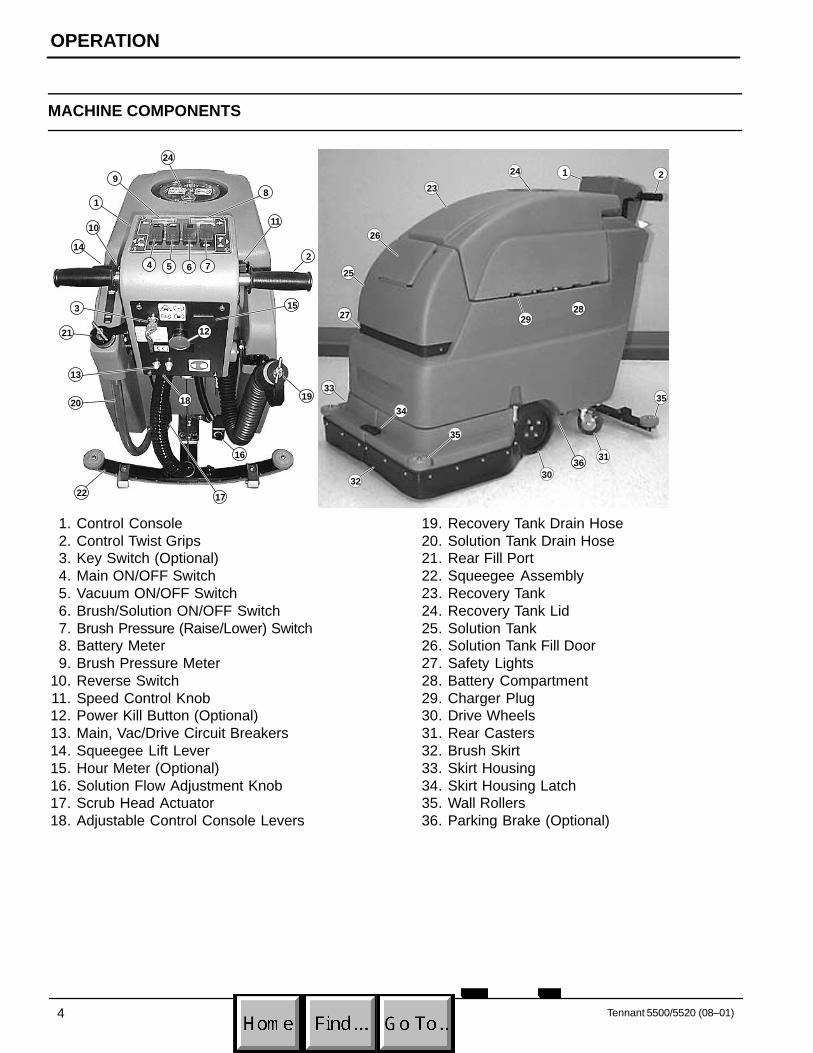
3. Carefully install batteries into battery tray atbottom of compartment and arrange battery postsas shown (Figure 2).
(+) (–)
(+)(–)
FIG. 2
ATTENTION: Do not drop batteries intocompartment, battery and machine housingdamage may result. This damage in not coveredby warranty.
4. Connect battery cables to battery posts as shown(RED TO POSITIVE & BLACK TO NEGATIVE)(Figure 2).
5. Turn on the main switch and check battery metercharge level to ensure batteries are fully charged.Charge if necessary (See BATTERY CHARGING).
MACHINE SETUP
ATTACHING SQUEEGEE ASSEMBLY
1. Turn main switch to the off position.
FOR SAFETY: Before leaving or servicingmachine, stop on level surface and turn offmachine.
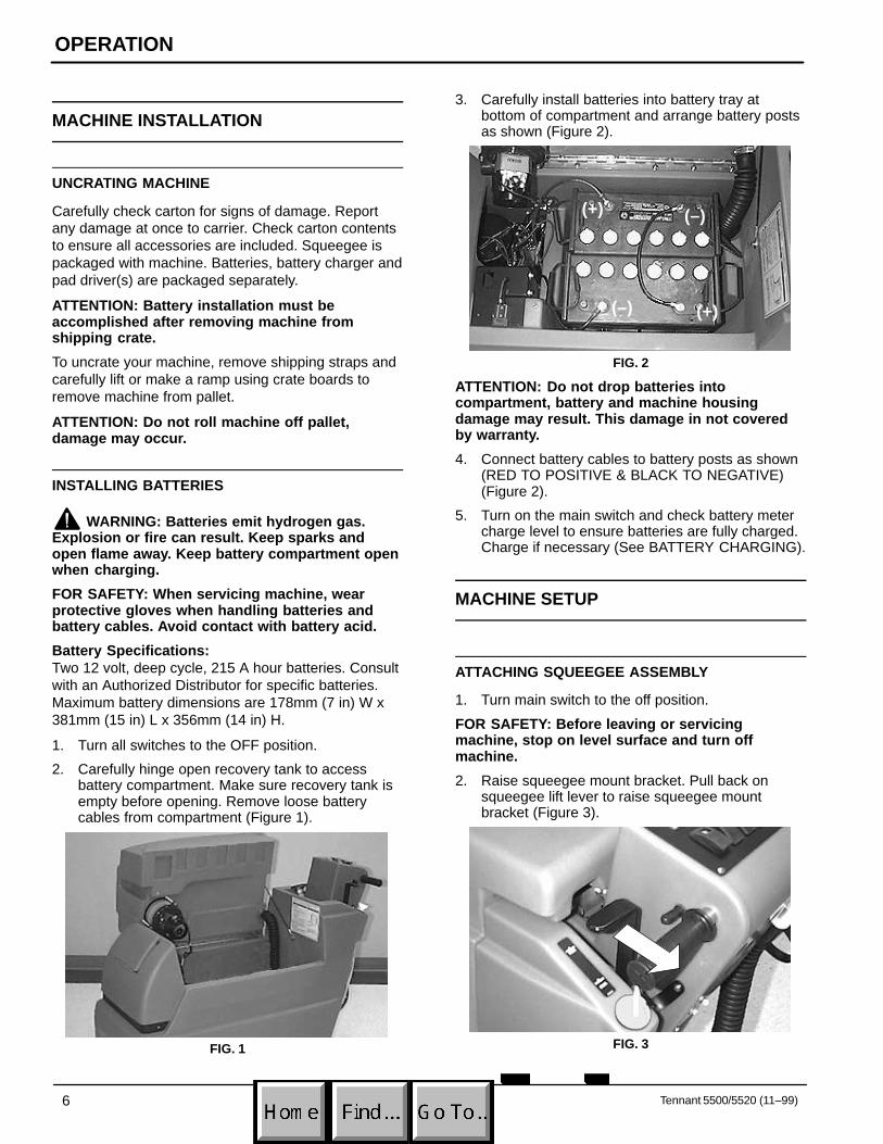
2. Raise squeegee mount bracket. Pull back onsqueegee lift lever to raise squeegee mountbracket (Figure 3).
FIG. 3

OPERATION
Tennant 5500/5520 (08–01) 7
3. Loosen two thumb knobs on squeegee assemblyand slide squeegee into slots on squeegee mountbracket. Squeegee roller wheels should faceoutward (Figure 4).
FIG. 4
4. Tighten thumb knobs securely.
5. Connect vacuum hose from machine to squeegeeassembly (Figure 5).
FIG. 5
INSTALLING BRUSH OR PAD DRIVERS
1. Turn main switch to the on position.
2. Raise scrub head. Press top half (–) of brushpressure switch to raise. Hold switch down untilscrub head actuator turns off (Figure 6).
FIG. 6
3. Turn main switch to the off position.
FOR SAFETY: Before leaving or servicingmachine, stop on level surface and turn offmachine.
4. Unfasten black latch at front of machine and hingeopen skirt housing to access motor hub (Figure 7).
FIG. 7
5. Select recommended pads or brushes that bestmeets your cleaning needs.
NOTE: Consult an authorized distributor for pad/brushrecommendations.
6. (For Pad Installation) Attach pads to pad driversbefore connecting drivers to motor hub. Securepads with plastic centerlock ring (Figure 8).
FIG. 8
7. Align pad driver mounting studs with slots in motorhub. Give the driver a quick turn toward the motorhub spring clip. Be certain that spring clip locksinto one of the studs before operating machine(Figure 9).

OPERATION
8 Tennant 5500/5520 (08–01)
FIG. 9
NOTE: Always make sure pad drivers and motor hubsurfaces are always clean before installing drivers.Clean surfaces will ease pad driver removal later.
8. Close skirt housing and refasten latch.
FILLING SOLUTION TANK
1. Transport machine to filling station. Raisesqueegee and brush when transporting.
2. Turn main switch to the off position.
3. Open solution fill door at front of machine and fillsolution tank with 64L (17 gal) of clean water,60°C (140°F) maximum temperature. Or use therear fill port to fill solution tank. Twist off plug andinsert hose to fill. The clear tube below the fill porthas 19L (5 gal) increment markers to indicateamount of water in tank (Figure 10).
FIG. 10
NOTE: If filling with a bucket be certain that bucket isclean. This will prevent possible solution line clogs.
4. Add cleaning chemical. See proper dilution ratioinstructions on bottle.
FOR SAFETY: When using machine, follow mixingand handling instructions on chemical containers.
ATTENTION: Use only recommended cleaningchemicals, DO NOT use substitutes. Consult anauthorized distributor for recommendations.
WARNING: Flammable materials can causean explosion or fire. Do not use flammablematerials in tank(s).
MACHINE OPERATION
FOR SAFETY: Do not operate machine unlessoperator manual is read and understood.
PRE–OPERATION CHECKS
� Sweep and dust mop floor to remove particles andother debris.
� Check battery meter charge level to ensurebatteries are fully charged (See BATTERYCHARGING).
� Check condition of pads or brushes.
� Check condition of squeegee blades.
1. Release parking brake lever if set.
2. Adjust control grips to a comfortable operatingheight, squeeze together the two levers below theconsole (Figure 11).
FIG. 11
3. Disengage squeegee lift lever from the up positionand lower squeegee (Figure 12).
FIG. 12
4. Turn main switch to the on position.

OPERATION
Tennant 5500/5520 (08–01) 9
5. Lower scrub head to floor by pressing bottom half(+) of brush pressure switch (Figure 13).
FIG. 13
6. Turn vacuum and brush switches to the onposition.
NOTE: The brushes and solution flow will not startuntil control grips are rotated.
7. Before starting, turn speed control knob to slowestsetting (Figure 14).
8. Begin scrubbing by rotating control grips forward.Gradually increase your speed by turning speedcontrol knob forward (Figure 14).
FIG. 14
9. Once machine begins to move, check the needleposition of the brush pressure meter. Depressbrush pressure switch to adjust brush pressure.Never operate machine in the red zone (Figure 15).
FIG. 15
ATTENTION: To prevent floor damage and brushmotor overload, do not operate brush pressuremeter in red zone.
10. To operate machine in reverse, simply pull reverseswitch backwards (one speed) (Figure 16).
FIG. 16
11. To stop machine, release control grips.
OPERATION
10 Tennant 5500/5520 (08–01)
WHILE OPERATING MACHINE
FOR SAFETY: When using machine, go slow oninclines and slippery surfaces.
WARNING: Flammable materials or reactivemetals can cause explosion or fire. Do not pickup.
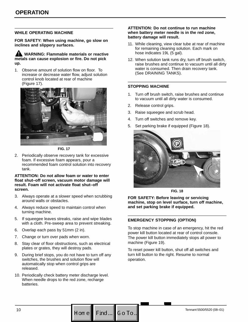
1. Observe amount of solution flow on floor. Toincrease or decrease water flow, adjust solutioncontrol knob located at rear of machine (Figure 17).
FIG. 17
2. Periodically observe recovery tank for excessivefoam. If excessive foam appears, pour arecommended foam control solution into recoverytank.
ATTENTION: Do not allow foam or water to enterfloat shut–off screen, vacuum motor damage willresult. Foam will not activate float shut–offscreen.
3. Always operate at a slower speed when scrubbingaround walls or obstacles.
4. Always reduce speed to maintain control whenturning machine.
5. If squeegee leaves streaks, raise and wipe bladeswith a cloth. Pre-sweep area to prevent streaking.
6. Overlap each pass by 51mm (2 in).
7. Change or turn over pads when worn.
8. Stay clear of floor obstructions, such as electricalplates or grates, they will destroy pads.
9. During brief stops, you do not have to turn off anyswitches, the brushes and solution flow willautomatically stop when control grips arereleased.
10. Periodically check battery meter discharge level.When needle drops to the red zone, rechargebatteries.
ATTENTION: Do not continue to run machinewhen battery meter needle is in the red zone,battery damage will result.
11. While cleaning, view clear tube at rear of machinefor remaining cleaning solution. Each mark onhose indicates 19L (5 gal).
12. When solution tank runs dry, turn off brush switch,raise brushes and continue to vacuum until all dirtywater is consumed. Then drain recovery tank.(See DRAINING TANKS).
STOPPING MACHINE
1. Turn off brush switch, raise brushes and continueto vacuum until all dirty water is consumed.
2. Release control grips.
3. Raise squeegee and scrub head.
4. Turn off switches and remove key.
5. Set parking brake if equipped (Figure 18).
FIG. 18
FOR SAFETY: Before leaving or servicingmachine, stop on level surface, turn off machine,and set parking brake if equipped.
EMERGENCY STOPPING (OPTION)
To stop machine in case of an emergency, hit the redpower kill button located at rear of control console.The power kill button immediately stops all power tomachine (Figure 19).
To reset power kill button, shut off all switches andturn kill button to the right. Resume to normaloperation.

OPERATION
Tennant 5500/5520 (08–01) 11
FIG. 19
CIRCUIT BREAKERS
The Machine is equipped with (4) circuit breakers toprotect machine from damage.
If circuit breakers should trip, the breakers will notreset immediately upon tripping. Determine reasonwhy breaker tripped, allow motor to cool and reset.
Brush motor circuit breakers will trip due to excessiveoverload on pad. Reduce pad pressure or replace padif breaker should trip. Brush motor circuit breakers(15amp) are located near charger plug.
The main (10amp) and drive/vacuum (35amp) circuitbreakers are located at rear of machine (Figure 20).
FIG. 20
DRAINING TANKS
FOR SAFETY: Before leaving or servicingmachine, stop on level surface and turn offmachine.
DRAINING RECOVERY TANK
When finished scrubbing or when refilling solutiontank, recovery tank should be drained and cleaned.
ATTENTION: If recovery tank is not drainedbefore refilling, foam or water will enter floatshut-off screen and vacuum motor damage willresult.
1. Remove drain hose from holder, position hoseover floor drain and twist off drain hose plug. Tocompletely drain recovery tank, hinge open tankand flip up tank support stand to rest tank on(Figure 21).
NOTE: If using a bucket to drain machine, do not usesame bucket for filling solution tank. This will preventpossible solution line clogs.
FIG. 21
2. Clean recovery tank after each use. Use a hose torinse out tank. Be careful not to spray water intofloat shut–off screen.
3. Replace drain hose plug tightly after draining.
DRAINING SOLUTION TANK
To drain leftover cleaning solution from solution tank,perform the following steps:
1. Pull clear hose off hose barb at rear of machineand drain solution into floor drain or bucket (Figure 22).

OPERATION
12 Tennant 5500/5520 (08–01)
FIG. 22
2. Rinse out solution tank and solution flow systemwith clean water after each use. This will preventclogging due to chemical buildup.
3. Reconnect solution tank drain hose securely afterdraining.
BATTERY CHARGING
NOTE: Recharge batteries ONLY after a total of 30minutes of use or more. This will prolong battery life.
The following charging instructions are intendedfor chargers supplied with machine. Only use acharger with the following specifications toprevent battery damage.
CHARGER SPECIFICATIONS:
� OUTPUT VOLTAGE - 24 VOLTS
� OUTPUT CURRENT - 25 AMPS MAXIMUM
� AUTOMATIC SHUTOFF CIRCUIT
� FOR DEEP CYCLE BATTERY CHARGING
NOTE: For optimum machine operation, keepbatteries charged at all times. Never let batteries set ina discharge condition.
WARNING: Batteries emit hydrogen gas.Explosion or fire can result. Keep sparks andopen flame away. Keep battery compartment openwhen charging.
FOR SAFETY: When servicing machine, wearprotective gloves when handling batteries andbattery cables. Avoid contact with battery acid.
1. Transport machine to a well–ventilated area forcharging.
2. Turn main switch to the off position.
3. Hinge open recovery tank to access batteries.Make sure recovery tank is empty before opening(Figure 23).
FIG. 23
4. Check fluid level (A) in each battery cell. Do notcharge batteries unless fluid is slightly coveringbattery plates (B). If needed, add just enoughdistilled water to slightly cover plates. DO NOToverfill. Batteries can overflow during charging dueto expansion. Replace cell caps before charging(Figure 24).
A
B
FIG. 24
5. Plug charger DC output connector to batteryconnector located near battery compartment. Flipup tank support stand and rest tank on stand(Figure 25).
FIG. 25
NOTE: Once charger is connected to machine,machine becomes inoperable.

OPERATION
Tennant 5500/5520 (8–01) 13
6. With the charger DC outlet connectordisconnected from batteries, plug charger powersupply cord into a grounded wall outlet (Figure 26).
Grounded Outlet
Grounding Edge/hole
Grounded3 Hole Outlet
Ground Pin
(120V) (230V)
FIG. 26
7. Charger will automatically begin charging andautomatically shut off when fully charged.
8. After charger has turned off, unplug charger frommachine then disconnect charger from wall outlet.
9. Recheck battery fluid level after charging. Ifneeded, add distilled water to bring level to bottomof sight tubes. Be certain to replace cell capssecurely and to wipe off the top of batteries with aclean cloth.
MACHINE MAINTENANCE
To keep machine in good working condition, simplyfollow the daily, weekly and monthly maintenanceprocedures.
FOR SAFETY: Before leaving or servicingmachine, stop on level surface and turn offmachine.
FOR SAFETY: When servicing machine,disconnect battery connections before working onmachine.
ATTENTION: Contact an Authorized ServiceCenter for machine repairs. Machine repairsperformed by other than an authorized person willvoid your warranty.
DAILY MAINTENANCE(Every 4 Hours of Operation)
1. Remove and clean pads/brushes. Never usesoiled pads when cleaning. Replace pads whenthey become loaded with residue.
2. Remove and clean lint from float shut–off screenlocated in recovery tank (Figure 27).
FIG. 27
3. Drain and rinse tanks thoroughly. After drainingtanks, hinge recovery tank until you can seevacuum intake hole at rear of tank. Remove anydebris in hole if necessary.
4. Raise squeegee and wipe it off with a dry cloth.Store squeegee in the up position to preventsqueegee damage.
5. Clean machine housing with a nonabrasive,nonsolvent cleaner.
ATTENTION: Do not power spray or hose offmachine. Electrical component damage mayresult.
6. Recharge batteries if needed.
WEEKLY MAINTENANCE(Every 20 Hours of Operation)
1. Flush out tanks and solution lines. Pour 750ml (24oz) of an acetic acid solution with 11.3L (3 gal) ofhot water, 60�C (140�F) max., into solution tank.Over a floor drain, activate solution flow briefly tofill solution line. Shut off power and let machine setover night. Rinse with clean water afterwards.
FOR SAFETY: When using machine, follow mixingand handling instructions on chemical containers.
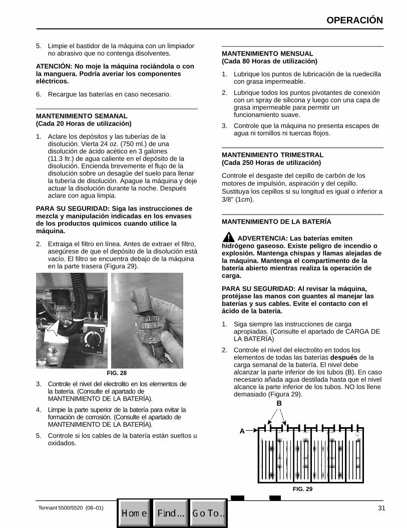
2. Remove inline strainer filter and rinse out. Beforeremoving filter, be certain solution tank is empty.Filter is located under machine at rear (Figure 28).
FIG. 28

OPERATION
14 Tennant 5500/5520 (08–01)
3. Check fluid level in battery cells. (See BATTERYMAINTENANCE).
4. Clean battery tops with to prevent corrosion. (SeeBATTERY MAINTENANCE).
5. Check for loose or corroded battery cables.
MONTHLY MAINTENANCE(Every 80 Hours of Operation)
1. Lubricate caster grease fittings with a waterresistant grease.
2. Lubricate all linkage pivot points with siliconespray then coat with a water resistant grease tomaintain a smooth operation.
3. Check machine for water leaks and loose nuts andbolts.
QUARTERLY MAINTENANCE(Every 250 Hours of Operation)
Check drive, vacuum and brush motors for carbonbrush wear, replace brushes if worn to a length of10mm (0.38 in) or less.
BATTERY MAINTENANCE
WARNING: Batteries emit hydrogen gas.Explosion or fire can result. Keep sparks andopen flame away. Keep battery compartment openwhen charging.
FOR SAFETY: When servicing machine, wearprotective gloves when handling batteries andbattery cables. Avoid contact with battery acid.
1. Always follow proper charging instructions (SeeBATTERY CHARGING).
2. After charging, check fluid level (A) in each batterycell of all batteries. The level should reach bottomof sight tubes (B). If needed, add just enoughdistilled water to reach bottom of sight tubes. DONOT overfill (Figure 29).
A
B
FIG. 29
3. Keep battery tops and terminals clean and dry.To clean batteries:a. Mix a strong solution of baking soda and
water.b. Brush solution sparingly over battery tops,
terminal and cable connectors.
NOTE: Do not allow baking soda solution to enterbattery cells.
c. Use wire brush to clean terminal post andcable connections.
d. After cleaning, apply a coating of clear batterypost protectant to terminals and cableconnections.
4. Check for loose or worn cables. Replace if worn.
TRANSPORTING MACHINE
When transporting machine by use of trailer or truck,be certain to follow tie–down procedures below:
FOR SAFETY: When using machine, go slow oninclines and slippery surfaces.
1. Remove squeegee from machine and raise scrubhead. Leave pad or brush installed.
2. Load machine using a recommended loadingramp.
3. Position front of machine up against front of trailerof truck. Once machine is positioned, lower brushhead.
4. Place a block behind the drive wheel and the rearcasters.
5. Place tie–down straps over top of machine andsecure straps to floor. It may be necessary toinstall tie–down brackets to the floor of your traileror truck.

OPERATION
Tennant 5500/5520 (06–99) 15
STORING MACHINE
1. Before storing machine, be certain to flush tanksand drain machine of all water.
2. Store machine in a dry area with squeegeeremoved and pad driver in the raised position.
3. Remove recovery lid to promote air circulation.
4. When storing machine, raise pad scrub head andsqueegee off floor to prevent damage.
ATTENTION: If storing machine if freezingtemperatures, be certain to drain machine of allwater. Damage due to freezing temperatures is notcovered by warranty.
ATTENTION: Do not expose machine to rain; storeindoors.
RECOMMENDED STOCK ITEMS
Refer to Parts List section for recommended stockitems. Stock Items are clearly identified with a bulletpreceding the parts description. See example below:

OPERATION
16 Tennant 5500/5520 (08–01)
TROUBLE SHOOTING
PROBLEM CAUSE SOLUTION
No power. Faulty main switch. Contact Service Center.
Batteries need charging. See CHARGING BATTERIES.
Faulty battery(s). Replace battery(s).
Loose battery cable. Tighten loose cable.
MAIN circuit breaker has tripped. Determine cause and reset circuitbreaker button.
Brush motors do not operate. Brush switch is not on. Turn on brush switch.
Control grips are not rotated. Rotate control grips.
Brush circuit breaker(s) has tripped. Clean or replace pad or brush andreset brush circuit breaker button.
Faulty brush motor or wiring. Contact Service Center.
Carbon brushes worn. Contact Service Center.
Faulty brush switch or solenoid. Contact Service Center.
Vacuum motor does not operate. Faulty vacuum switch. Contact Service Center.
Vacuum circuit breaker has tripped. Remove obstruction and resetbreaker.
Faulty vacuum motor or wiring. Contact Service Center.
Carbon brushes worn. Contact Service Center.
Drive motor does not operate. Drive motor circuit breaker hastripped.
Determine cause and reset breaker.
Faulty speed control circuit board orconnection.
Contact Service Center.
Faulty solenoid. Contact Service Center.
Faulty drive motor. Contact Service Center.
Faulty wiring. Contact Service Center.
Worn carbon brushes. Contact Service Center.
Drive motor operates improperly. Faulty potentiometer or speed controlboard.
Contact Service Center.
Loose wire connection Contact Service Center.
Little or no solution flow. Solution line or solution tank filter isclogged.
Remove hose and blow compressedair through it. Flush solution tank aftereach use.
Solution valve or solenoid is clogged. Remove valve or solenoid and clean. Do not scratch inside of valve.
Faulty solution switch or solenoid. Contact Service Center.
Solution flow adjustment knob needsadjusting.
Turn solution flow knob clockwise toincrease flow.
Short run time. Batteries not fully charged. Charge batteries.
Bad cell in one or more batteries. Replace battery.
Batteries need maintenance. See BATTERY MAINTENANCE.
Faulty charger. Replace battery charger.

OPERATION
Tennant 5500/5520 (06–99) 17
TROUBLE SHOOTING –continued
PROBLEM CAUSE SOLUTION
Poor water pick up. Recovery tank is full. Empty recovery tank.
Ball float shut–off screen inside recov-ery tank is clogged.
Remove screen and clean.
Squeegee is clogged with debris. Clean squeegee.
Squeegee blades are worn. Replace squeegee blades.
Squeegee thumbscrews are loose. Tighten thumbscrews.
Vacuum hose connections are looseor hose has a hole.
Push hose cuffs firmly on connections.Replace hose if damaged.
Vacuum hose is clogged with debris. Remove clogged debris.
Recovery tank inlet hole is obstructed. Empty recovery tank and tilt tank side-ways to access inlet hole, removeobstruction.
Tank gasket is defective. Replace gasket.
Drain hose plug is loose. Tighten drain plug.
Recovery tank lid is loose. Tighten lid.
Vacuum motor is loose. Contact Service Center.
Battery charge level is low. Charge batteries. Do not run machinewhen battery meter is in the red zone.
Safety lights do not work. Flasher is burned out. Contact Service Center.
SPECIFICATIONS
MODEL 5500 5520
LENGTH 1270 mm (50 in) 1270 mm (50 in)
WIDTH 660 mm (26 in) 711mm (28 in)
HEIGHT 990 mm (39 in) 990 mm (39 in)
WEIGHT 170 kg (375lb)/272 Kg (600lb) with batteries 170 kg (375lb)/272 Kg (600lb) with batteries
SOL./REC TANK CAPACITY 64 L (17 Gal) 64 L (17 Gal)
SPEED CONTROL Variable Fwd. / Fixed Rev. Variable Fwd. / Fixed Rev.
CLEANING SPEED (MAX) 2229.6m2 (24,000 sq ft) per hour 2415.4m2 (26,000 sq ft) per hour
CLEANING PATH WIDTH 587 mm (23.123 in) 638 mm (25.13 in)
PAD DIAMETER 2 – 305mm (12 in) 2 – 330mm (13 in)
PAD PRESSURE Variable 36–68Kg (80–150lb) Variable 36–68Kg (80–150lb)
SQUEEGEE WIDTH 787 mm (31 in) 863 mm (34 in)
DRIVE SYSTEM Transaxle, .2 h.p., 24V Transaxle, .2 h.p., 24V
BRUSH MOTOR 2 – .75 h.p., 220 rpm, 24V, 20A, 550W 2 – .75 h.p., 220 rpm, 24V, 20A, 550W
VACUUM MOTOR .75 h.p., 3–stage 5.7, 24V, 21A, 550W .75 h.p., 3–stage 5.7, 24V, 21A, 550W
WATER LIFT 1727 mm (68 in) 1727 mm (68 in)
BATTERIES 2–12V, 215AH 2–12V, 215AH
RUN TIME PER CHARGE Up to 4 3/4 hours Up to 4 3/4 hours
DECIBEL RATING AT OPERATOR’SEAR, INDOORS ON TILE.
75 dB(A) 75 dB(A)
OPERACIÓN
18 Tennant 5500/5520 (08–01)
Este manual acompaña a todos los modelos estándarnuevos. En él se indican las instrucciones necesariaspara la utilización y el mantenimiento de la máquina.Lea el manual entero para comprender elfuncionamiento de la máquina antes de utilizarla orevisarla.
Esta máquina le proporcionará un servicio excelente.Sin embargo, obtendrá los mejores resultados al costemínimo si:
� Utiliza la máquina con un cuidado razonable.
� Revisa la máquina periódicamente - según lasinstrucciones de mantenimiento adjuntas.
� Realiza el mantenimiento de la máquina con piezasrepuesto del fabricante suministradas por oequivalentes.
DATOS DE LA MÁQUINA
Modelo No.:
Fecha de preparacion:
Nº de serie:
Sírvase llenar los datos en el momento de la preparación parareferencia en el futuro.
ÍNDICE
MEDIDAS DE SEGURIDAD 19. . . . . . . . . . . . . . . .
COMPONENTES ESTÁNDAR DE LA MÁQUINA 20. . . . . . . . . . . . . . . . . . . . . . . . . . . .
SÍMBOLOS DEL PANEL DE CONTROL 21. . . .
INSTALACIÓN DE LA MÁQUINA 22. . . . . . . . . . DESEMBALADO DE LA MÁQUINA 22. . . . . . INSTALACIÓN DE LAS BATERÍAS 22. . . . . .
PREPARACIÓN DE LA MÁQUINA 23. . . . . . . . . . FIJACIÓN DEL CONJUNTO DE LA ESCOBILLA DE GOMA 23. . . . . . . . . . . . . . . . INSTALACIÓN DE LOS IMPULSORES DEL CEPILLO O LA ALMOHADILLA 23. . . . . LLENADO DEL DEPÓSITO DE LA DISOLUCIÓN 24. . . . . . . . . . . . . . . . . . . . . .
FUNCIONAMIENTO DE LA MÁQUINA 25. . . . . . COMPROBACIONES PREVIAS A LA PUESTA EN FUNCIONAMIENTO 25. . . . . . . AL UTILIZAR LA MÁQUINA 26. . . . . . . . . . . . . PARADA DE LA MÁQUINA 27. . . . . . . . . . . . . PARADA DE EMERGENCIA (OPCIÓN) 27. . CORTACIRCUITOS 28. . . . . . . . . . . . . . . . . . . .
VACIADO DE LOS DEPÓSITOS. 28. . . . . . . . . . . VACIADO DEL DEPÓSITO DE RECUPERACIÓN 28. . . . . . . . . . . . . . . . . . . . . VACIADO DEL DEPÓSITO DE LA DISOLUCIÓN 28. . . . . . . . . . . . . . . . . . . . . .
CARGA DE LA BATERÍA 29. . . . . . . . . . . . . . . . . .
MANTENIMIENTO DE MAQUINA 30. . . . . . . . . . . MANTENIMIENTO DIARIO 30. . . . . . . . . . . . . MANTENIMIENTO SEMANAL 31. . . . . . . . . . . MANTENIMIENTO MENSUAL 31. . . . . . . . . . MANTENIMIENTO TRIMESTRAL 31. . . . . . .
MANTENIMIENTO DE LA BATERÍA 31. . . . .
TRANSPORTE DE LA MÁQUINA 32. . . . . . . . . . .
ALMACENAMIENTO DE LA MÁQUINA 32. . . . .
RECOMENDACIONES PARA EL ALMACENAMIENTO 32. . . . . . . . . . . . . . . . . . . . . .
LOCALIZACIÓN DE AVERÍAS 33. . . . . . . . . . . . .
ESPECIFICACIONES 35. . . . . . . . . . . . . . . . . . . . .
DIAGRAMAS ELECTRICAS 36. . . . . . . . . . . . . . .
LISTA DE PIEZAS 38. . . . . . . . . . . . . . . . . . . . . . . . CEPILLO DEL REEMPLAZO Y GRUPO DEL MANDO DE LA ALMOHADILLA 38. . . . . . . . . GRUPE DEL DEPÓSITO DE DISOLUCIÓN 40. . . . . . . . . . . . . . . . . . . . . . CONJUNTO DEPOSITO RECUPERAR 42. . . . . . . . . . . . . . . . . . . . . . . . . CONJUNTO CONSOLA DE CONTROLES 44. . . . . . . . . . . . . . . . . . . . . . GRUPO DEL ELÉCTRICO/BATERÍA 46. . . . . GRUPO DE TRANMISIÓN 48. . . . . . . . . . . . . . CONJUNTO IMPULSO DE CEPILLO 50. . . . CONJUNTO JUEGO DE CEPILLO 52. . . . . . . CONJUNTO DE PALANCAS SOLUCIÓN 54. CONJUNTO DE PALETA PLANCAS 56. . . . . CONJUNTO PALETA ENCORUADO 58. . . . .
OPCIONES 60. . . . . . . . . . . . . . . . . . . . . . . . . . . . . . ES� JUEGO 60. . . . . . . . . . . . . . . . . . . . . . . . . . GROUPE D’ASPIRATION ETRACLETTE À MAIN 62. . . . . . . . . . . . . . . . . . . . HOUR METER, EMERGENCY STOP, KEYSWITCH AND LOW VOLTAGE KITS 63. . . . . . . . . . . . . . . . . . . . . . . JUEGO DE CONVERSIÓN 64. . . . . . . . . . . . .

OPERACIÓN
19Tennant 5500/5520 (08–01)
MEDIDAS DE SEGURIDAD
Esta máquina está destinada al uso comercial. Estádiseñada para fregar suelos en recintos cerrados y nodebe utilizarse para ningún otro uso. Utiliceúnicamente los cepillos, almohadillas y disolucioneslimpiadoras recomendados.
En este manual se utilizan los siguientes símbolos depeligro, cuyo significado se indica a continuación:
ADVERTENCIA: Para advertir sobre riesgos ohábitos peligrosos que podrían causar lesionescorporales graves o fatales.
PARA SU SEGURIDAD: Para indicar lasoperaciones que deben realizarse para unautilización segura del equipo.
La siguiente información indica las condicionespotencialmente peligrosas para el operario o equipo:
PARA SU SEGURIDAD:
1. No utilice la máquina:– Salvo que esté adecuadamente cualificado
y autorizado.– Salvo que haya leído y comprendido el
manual del operario.– En áreas donde exista material inflamable
o explosivo salvo que esté especialmentediseñada para utilizarla en estas zonas.
2. Antes de arrancar la máquina:– Asegúrese de que todos los dispositivos
de control se encuentran en su sitio yfuncionan correctamente.
3. Al utilizar la máquina:– Conduzca despacio en pendientes y
superficies resbaladizas.– Conduzca con cuidado al desplazarse
marcha atrás.– Cumpla siempre las normas de tráfico y
seguridad.– Informe inmediatamente si la máquina
presenta averías o funcionaincorrectamente.
– Siga las instrucciones de manipulación ymezcla indicadas en los envases de losproductos químicos.
4. Antes de estacionar o revisar la máquina:– Deténgase en una superficie plana.– Apague la máquina.– Ponga el freno de estacionamiento.
5. Al revisar la máquina:– Evite las partes en movimiento. No lleve
chaquetas, camisas o mangas sueltas.– Calce las ruedas de la máquina antes de
levantarla con un gato.– Utilice un gato o elevador con capacidad
suficiente para elevar la máquina.– Desconecte las conexiones de la batería
antes de empezar a trabajar en la máquina.– Protéjase las manos con guantes al
trabajar con las baterías o sus cables.– Evite el contacto con el ácido de la batería.– Utilice piezas de recambio suministradas o
aprobadas por el fabricante.
ADVERTENCIA: Las baterías emitenhidrógeno gaseoso. Existe peligro de incendio oexplosión. Mantenga chispas y llamas alejadas dela máquina. Mantenga el compartimento de labatería abierto mientras realiza la operación decarga.
ADVERTENCIA: Los materiales inflamablespueden provocar explosiones o incendios. Noutilice materiales inflamables en los depósitos.
ADVERTENCIA: Los materiales inflamables ometales reactivos pueden provocar explosiones oincendios. No los recoja.

OPERACIÓN
20 Tennant 5500/5520 (08–01)
COMPONENTES ESTÁNDAR DE LA MÁQUINA
1
1110
9
4 765
1221
13
20
1722
23
24
25
26
2728
29
30
31
32
35
3533
3418
2
15
2
16
8
14
19
3
1
24
36
1. Consola de control2. Mandos giratorios de control3. Contacto para la llave (Opción)4. Interruptor principal de encendido/apagado5. Interruptor de encendido/apagadode la
aspiración6. Interruptor de encendido/apagado del
cepillo/de la disolución7. Interruptor de (subir/bajar) de la presión
del cepillo8. Indicador del nivel de carga de la baterías9. Indicador de la presión del cepillo
10. Interruptor de marcha atrás11. Mando de control de la velocidad12. Botón de parada (Opción)13. Cortacircuitos principal, de impulsión /
de aspiración14. Palanca de elevación de la escobilla
de goma15. Contador de horas (Opción)16. Mando de ajuste del flujo de la disolución17. Actuador del cabezal de fregado
18. Palancas de la consola de control ajustable19. Manguera de vaciado del depósito
de recuperación20. Manguera de vaciado del depósito de
la disolución21. Orificio trasero de llenado22. Conjunto de la escobilla de goma23. Depósito de recuperación24. Tapa del depósito de recuperación25. Depósito de la disolución26. Puerta de llenado del depósito de
la disolución27. Luces de seguridad28. Compartimento de la batería29. Enchufe del cargador30. Ruedas impulsoras31. Ruedecillas traseras32. Aleta del cepillo33. Bastidor de la aleta34. Pestillo del bastidor de la aleta35. Rodillos de pared36. Freno de estacionamiento (Opción)

OPERACIÓN
21Tennant 5500/5520 (08–01)
SÍMBOLOS DEL PANEL DE CONTROL
Circuito princi-pal
Velocidad rápida Cortacircitos del Lea el Manual
Velocidad lentaAspiración
Marcha atrás
Cortacircuitos del
Cepillo
Indicador del
Escobilla deMenos presión
Cortacircuitos delMás presión Escobilla de
Indicador de la
del cepillo
del cepillo
goma elevada
goma bajada
motor del cepillolateral derecho
Cortacircitos delmotor del cepillolateral izquierdo
motor de aspiración
circuito principal
antes de utilizarla máquina
nivel de cargade la batería
presión del cepillo

OPERACIÓN
22 Tennant 5500/5520 (08–01)
INSTALACIÓN DE LA MÁQUINA
DESEMBALADO DE LA MÁQUINA
Compruebe cuidadosamente si la caja de cartónmuestra daños. En caso de que así sea informeinmediatamente al transportista. Controle el contenidode la caja para asegurarse de que incluye todos losaccesorios. La escobilla de goma está embalada conla máquina. Las baterías y su cargador y el(los)impulsor(es) de la almohadilla están embaladosaparte.
ATENCIÓN: La instalación de la batería deberealizarse después de desembalar totalmente lamáquina.
Para desembalar la máquina, retire las cintas desujeción y levántela cuidadosamente o utilice unarampa formada con las planchas de embalaje pararetirar la máquina del pallet.
ATENCIÓN: No retire la máquina del pallethaciéndola rodar porque podría averiarla.
INSTALACIÓN DE LAS BATERÍAS
ADVERTENCIA: Las baterías emitenhidrógeno gaseoso. Existe peligro de incendio oexplosión. Mantenga chispas y llamas alejadas dela máquina. Mantenga el compartimento de labatería abierto mientras realiza la operación decarga.
PARA SU SEGURIDAD: Al revisar la máquina,protéjase las manos con guantes al manejar lasbaterías y sus cables. Evite el contacto con elácido de la batería.
Especificaciones de la Batería:Dos baterías de 12 voltios de ciclo profundo. Consultea un distribuidor autorizado sobre bateríasespecíficas. Las dimensiones máximas de la bateríason 178mm (7 in) ancho x 381mm (15 in) largo x356mm (14 in) alto.
1. Sitúe todos los interruptores en la posición deAPAGADO.
2. Abra cuidadosamente el depósito de recuperaciónpara acceder al compartimento de la batería.Extraiga del compartimento los cables sueltos dela batería (Figura 1).
FIG. 1
3. Instale con cuidado las baterías en la bandeja dela batería que se encuentra en el fondo delcompartimento e instale los bornes de la bateríacomo se muestra (Figura 2).
(+) (–)
(+)(–)
FIG. 2
ATENCIÓN: Deposite las baterías en elcompartimento, no las deje caer, tanto la bateríacomo su soporte podrían averiarse. La garantía nocubre este tipo de desperfectos.
4. Conecte los cables de la batería a los bornes de labatería como se muestra (ROJO EN ELPOSITIVO Y NEGRO EN EL NEGATIVO) (Figura 2).
5. Gire la llave y encienda el interruptor principal ycontrole el nivel de carga de la batería. Cargue labatería en caso necesario. (Consulte el apartadode CARGA DE LA BATERÍA).

OPERACIÓN
23Tennant 5500/5520 (08–01)
PREPARACIÓN DE LA MÁQUINA
FIJACIÓN DEL CONJUNTO DE LA ESCOBILLA DEGOMA
PARA SU SEGURIDAD: Antes de abandonar orevisar la máquina, deténgase en una superficieplana, apague la máquina y ponga el freno deestacionamiento.
1. Eleve el soporte de montaje de la escobilla degoma tirando hacia atrás de la palanca deelevación de la escobilla de goma (Figura 3).
FIG. 3
2. Afloje los dos tornillos de orejas del conjunto de laescobilla de goma e introduzca dicha escobilladeslizándola en las ranuras del soporte demontaje de la escobilla de goma. Las ruedas delrodillo de la escobilla de goma deben mirar haciaafuera (Figura 4).
FIG. 4
3. Fije bien los tornillos de orejas.
4. Conecte la manguera de aspiración de la máquinaal conjunto de la escobilla de goma (Figura 5).
FIG. 5
INSTALACIÓN DE LOS IMPULSORES DELCEPILLO O LA ALMOHADILLA
1. Gire la llave y encienda el interruptor principal.
2. Eleve totalmente el cabezal de fregado pulsandola mitad superior (–) del interruptor de la presióndel cepillo (Figura 6).
FIG. 6
3. Sitúe el interruptor principal y la llave de contactoen la posición de apagado.
PARA SU SEGURIDAD: Antes de abandonar orevisar la máquina, deténgase en una superficieplana, apague la máquina y ponga el freno deestacionamiento.
OPERACIÓN
24 Tennant 5500/5520 (08–01)
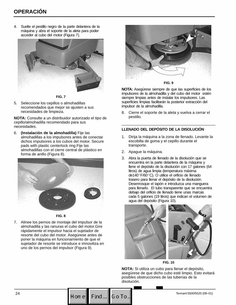
4. Suelte el pestillo negro de la parte delantera de lamáquina y abra el soporte de la aleta para poderacceder al cubo del motor (Figura 7).
FIG. 7
5. Seleccione los cepillos o almohadillasrecomendados que mejor se ajusten a susnecesidades de limpieza.
NOTA: Consulte a un distribuidor autorizado el tipo decepillo/almohadilla recomendado para susnecesidades.
6. (Instalación de la almohadilla) Fije lasalmohadillas a los impulsores antes de conectardichos impulsores a los cubos del motor. Securepads with plastic centerlock ring.Fije lasalmohadillas con el cierre central de plástico enforma de anillo (Figura 8).
FIG. 8
7. Alinee los pernos de montaje del impulsor de laalmohadilla y las ranuras el cubo del motor.Girerápidamente el impulsor hacia el sujetador deresorte del cubo del motor. Asegúrese antes deponer la máquina en funcionamiento de que elsujetador de resorte se introduce e imnoviliza enuno de los pernos del impulsor (Figura 9).
FIG. 9
NOTA: Asegúrese siempre de que las superficies de losimpulsores de la almohadilla y del cubo del motor esténsiempre limpias antes de instalar los impulsores. Lassuperficies limpias facilitarán la posterior extracción delimpulsor de la almohadilla.
8. Cierre el soporte de la aleta y vuelva a cerrar elpestillo.
LLENADO DEL DEPÓSITO DE LA DISOLUCIÓN
1. Dirija la máquina a la zona de llenado. Levante laescobilla de goma y el cepillo durante eltransporte.
2. Apague la máquina.
3. Abra la puerta de llenado de la disolución que seencuentra en la parte delantera de la máquina yllene el depósito de la disolución con 17 galones (64litros) de agua limpia (temperatura máximade140�F/60�C). O utilice el orificio de llenadotrasero para llenar el depósito de la disolución.Desenrosque el tapón e introduzca una manguerapara llenarlo. El tubo transparente que se encuentradebajo del orificio de llenado tiene unas marcascada 5 galones (19 litros) que indican el volumen deagua del depósito (Figura 10).
FIG. 10
NOTA: Si utiliza un cubo para llenar el depósito,asegúrese de que dicho cubo esté limpio. Esto evitaráposibles obstrucciones de las tuberías de ladisolución.

OPERACIÓN
25Tennant 5500/5520 (08–01)
4. Añada el producto de limpieza. Consulte en lasinstrucciones del envase la proporción correcta dela disolución.
PARA SU SEGURIDAD: Siga las instrucciones demezcla y manipulación indicadas en los envasesde los productos químicos cuando utilice lamáquina.
ATENCIÓN: Utilice únicamente productos delimpieza recomendados, NO utilice sustitutos.Consulte a un distribuidor autorizado acerca delos productos de limpieza recomendados.
ADVERTENCIA: Utilice únicamente productosquímicos de limpieza no inflamables.
FUNCIONAMIENTO DE LA MÁQUINA
PARA SU SEGURIDAD: No utilice la máquinasalvo que el operario haya leído y comprendido elmanual de instrucciones.
COMPROBACIONES PREVIAS A LA PUESTA ENFUNCIONAMIENTO
� Barra el suelo para eliminar partículas y otrosrestos.
� Controle el nivel de carga de la batería paraasegurarse que de las baterías estáncompletamente cargadas. (Consulte el apartadoCARGA DE LAS BATERÍAS)
� Controle el estado de los cepillos o almohadillas.
� Controle el estado de las láminas de la escobilla degoma.
1. Quite el freno de estacionamiento si está puesto.
2. Ajuste los mandos de control a una altura defuncionamiento cómoda, junte las dos palancasque se encuentran bajo la consola (Figura 11).
FIG. 11
3. Suelte la palanca de elevación de la escobilla degoma de la posición superior y baje la escobilla degoma (Figura 12).
FIG. 12
4. Gire la llave y encienda el interruptor principal.
5. Baje el cabezal de fregado hasta el suelo pulsandola mitad inferior (+) del interruptor de la presión del cepillo (Figura 13).
FIG. 13
6. Encienda los interruptores de aspiración y delcepillo.
OPERACIÓN
26 Tennant 5500/5520 (08–01)
NOTA: Los cepillos y el flujo de disolución noempezarán a funcionar hasta girar los mandos decontrol.
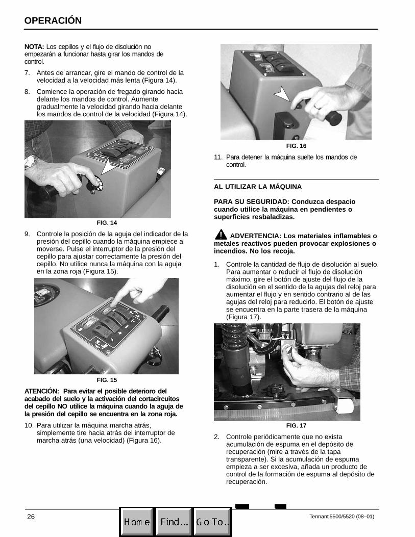
7. Antes de arrancar, gire el mando de control de lavelocidad a la velocidad más lenta (Figura 14).
8. Comience la operación de fregado girando haciadelante los mandos de control. Aumentegradualmente la velocidad girando hacia delantelos mandos de control de la velocidad (Figura 14).
FIG. 14
9. Controle la posición de la aguja del indicador de lapresión del cepillo cuando la máquina empiece amoverse. Pulse el interruptor de la presión delcepillo para ajustar correctamente la presión delcepillo. No utilice nunca la máquina con la agujaen la zona roja (Figura 15).
FIG. 15
ATENCIÓN: Para evitar el posible deterioro delacabado del suelo y la activación del cortacircuitosdel cepillo NO utilice la máquina cuando la aguja dela presión del cepillo se encuentra en la zona roja.
10. Para utilizar la máquina marcha atrás,simplemente tire hacia atrás del interruptor demarcha atrás (una velocidad) (Figura 16).
FIG. 16
11. Para detener la máquina suelte los mandos decontrol.
AL UTILIZAR LA MÁQUINA
PARA SU SEGURIDAD: Conduzca despaciocuando utilice la máquina en pendientes osuperficies resbaladizas.
ADVERTENCIA: Los materiales inflamables ometales reactivos pueden provocar explosiones oincendios. No los recoja.
1. Controle la cantidad de flujo de disolución al suelo.Para aumentar o reducir el flujo de disoluciónmáximo, gire el botón de ajuste del flujo de ladisolución en el sentido de la agujas del reloj paraaumentar el flujo y en sentido contrario al de lasagujas del reloj para reducirlo. El botón de ajustese encuentra en la parte trasera de la máquina(Figura 17).
FIG. 17
2. Controle periódicamente que no existaacumulación de espuma en el depósito derecuperación (mire a través de la tapatransparente). Si la acumulación de espumaempieza a ser excesiva, añada un producto decontrol de la formación de espuma al depósito derecuperación.

OPERACIÓN
27Tennant 5500/5520 (08–01)
ATENCIÓN: No permita que el agua o la espumase introduzcan en el filtro del flotador de cierre, elmotor de aspiración resultaría dañado. Laespuma no activará el filtro del flotador de cierre.
3. Reduzca la velocidad siempre que friegue cercade paredes u obstáculos.
4. Para mantener el control sobre la máquina, reduzcala velocidad siempre que tome curvas.
5. Si la escobilla de goma deja marcas, eleve laescobilla de goma y limpie las láminas con unpaño. Realice un barrido previo de la zona paraevitar la formación de marcas.
6. Haga que los diferentes pases se superpongan 2”(5cm).
7. Cambie o gire las almohadillas cuando esténsucias.
8. Manténgase alejado de obstáculos del suelo comoplacas eléctricas o rejillas, romperían lasalmohadillas.
9. No es necesario apagar ningún interruptor durantelas paradas cortas, los cepillos y el flujo de ladisolución se detendrán automáticamente al soltarlos mandos de control.
10. Controle periódicamente el nivel de carga de labatería. Recargue las baterías cuando la aguja delindicador se encuentre en la zona roja.
ATENCIÓN: No utilice la máquina cuando la agujadel indicador del nivel de carga de la batería seencuentre en la zona roja o podría dañar labatería.
11. Controle la cantidad de disolución que quedadurante la operación de limpieza a través del tuboindicador transparente. Cada marca de lamanguera indica cinco galones / 19 litros.
12. Cuando se vacíe el depósito de la disolución, vacíeel depósito de recuperación. (Consulte el apartadode VACIADO DE LOS DEPÓSITOS).
PARADA DE LA MÁQUINA
1. Apague el interruptor del cepillo, eleve los cepillos ycontinúe aspirando hasta que se haya recogido todoel agua sucia.
2. Suelte los mandos de control.
3. Eleve la escobilla de goma y el cabezal defregado.
4. Apague los interruptores y retire la llave delcontacto.
5. Ponga el freno de estacionamiento tirando haciaatrás de la palanca (Figura 19).
FIG. 18
PARA SU SEGURIDAD: Antes de abandonar orevisar la máquina, deténgase en una superficieplana, apague la máquina y ponga el freno deestacionamiento.
PARADA DE EMERGENCIA (OPCIÓN)
Para detener la máquina en caso de emergencia,pulse el botón rojo de parada situado en la partetrasera de la consola de control. El botón de paradainterrumpe inmediatamente la alimentación eléctrica ala máquina (Figura 20).
Para reajustar el botón de parada, apague todos losinterruptores y gire el botón de parada hacia laderecha. Reanude el funcionamiento normal.
FIG. 19

OPERACIÓN
28 Tennant 5500/5520 (08–01)
CORTACIRCUITOS
La máquina está equipada con (4) cortacircuitos deprotección.
Si se activan los cortacircuitos, no los reajusteinmediatamente. Determine la causa de la activacióndel cortacircuitos, deje que el motor se enfríe yreajuste dicho cortacircuitos.
Los cortacircuitos del motor del cepillo se activarándebido a una carga excesiva de la almohadilla.Reduzca la presión de la almohadilla o sustitúyala sise activa el cortacircuitos Los cortacircuitos del motordel cepillo (15amp) se encuentran cerca del enchufedel cargador.
Los cortacircuitos principal (10amp) y deimpulsión/aspiración (35amp) se encuentran en la partetrasera de la máquina (Figura 20).
FIG. 20
VACIADO DE LOS DEPÓSITOS
PARA SU SEGURIDAD: Antes de abandonar orevisar la máquina, deténgase en una superficieplana, apague la máquina y ponga el freno deestacionamiento.
VACIADO DEL DEPÓSITO DE RECUPERACIÓN
Vacíe y limpie del depósito de recuperación al terminarla operación de fregado o rellenar el depósito dedisolución.
ATENCIÓN: Si no vacía el depósito derecuperación antes de rellenarlo, podríaintroducirse agua o espuma en el filtro delflotador de cierre y dañar el motor de aspiración.
1. Extraiga la manguera de vaciado de su soporte,coloque la manguera en el desagüe y abra eltapón de la manguera de vaciado. Para vaciarcompletamente el depósito de recuperación abrala tapa del depósito lateralmente y coloque labarra de apoyo para colocar el depósito sobre ella(Figura 21).
NOTA: Si utiliza un cubo para vaciar la máquina, noutilice el mismo cubo para llenar el depósito de ladisolución. Esto evitará que las tuberías de ladisolución se bloqueen.
FIG. 21
2. Aclare el depósito de recuperación después decada uso. Utilice una manguera para aclarar eldepósito. Tenga cuidado de no introducir agua enel filtro del flotador.
3. Vuelva a colocar bien el tapón de la manguera devaciado después de la operación de vaciado.
VACIADO DEL DEPÓSITO DE LA DISOLUCIÓN
Para vaciar la disolución que no se ha utilizado deldepósito de la disolución siga los siguientes pasos:
1. Saque la manguera transparente que seencuentra en la parte trasera de la máquina de susoporte y vacíe la disolución en un desagüe ocubo (Figura 22).
FIG. 22

OPERACIÓN
29Tennant 5500/5520 (08–01)
2. Aclare el depósito de la disolución y el sistema deflujo de la disolución con agua limpia después decada uso. Esto evitará el bloqueo debido a laacumulación de productos químicos.
3. Vuelva a colocar la manguera transparente en susoporte. Asegúrese de introducirla bien.
CARGA DE LA BATERÍA
NOTA: Recargue las baterías SÓLO después dehaberlas utilizado durante un tiempo mínimo total de30 minutos. Esto prolongará la vida de la batería.
Las siguientes instrucciones de carga son válidasexclusivamente para los cargadores de 24Vsuministrados con la máquina. En cualquier caso,utilice un cargador con las siguientescaracterísticas para evitar el deterioro de lasbaterías.
ESPECIFICACIONES DEL CARGADOR:
� VOLTAJE DE SALIDA 24 VOLTIOS
� CORRIENTE DE SALIDA – 25 AMP MÁXIMO
� CIRCUITO DE APAGADO AUTOMÁTICO
� PARA CARGA PROFUNDA DE LA BATERÍA
NOTA: Para un funcionamiento óptimo de la máquinamantenga siempre cargadas las baterías. Nunca dejebaterías descargadas puestas.
ADVERTENCIA: Las baterías emitenhidrógeno gaseoso. Existe peligro de incendio oexplosión. Mantenga chispas y llamas alejadas dela máquina. Mantenga el compartimento de labatería abierto mientras realiza la operación decarga.
PARA SU SEGURIDAD: Al revisar la máquina,protéjase las manos con guantes al manejar lasbaterías y sus cables. Evite el contacto con elácido de la batería.
1. Dirija la máquina a una zona bien ventilada paracargar las baterías.
2. Apague todos los interruptores y coloque la llaveen posición apagada.
PARA SU SEGURIDAD: Antes de abandonar orevisar la máquina, deténgase en una superficieplana, apague la máquina y ponga el freno deestacionamiento.
3. Abra la tapa del depósito de recuperación paratener acceso a las baterías (Figura 23).
FIG. 23
4. Controle el nivel de electrolito (A) de cadaelemento de la batería. No cargue las bateríassalvo que el electrolito cubra ligeramente lasplacas de la batería (B). En caso necesarionecesario añada el agua destilada necesaria paraque las placas se cubran ligeramente. NO llene labatería excesivamente. El agua de las bateríaspuede derramarse durante la carga de las mismasdebido a la expansión. Coloque los tapones antesde cargar (Figura 24).
A
B
FIG. 24
ATENCIÓN: Para evitar el riesgo de descargaseléctricas, el cargador DEBE estar conectado auna toma de tierra mientras se utiliza paraproteger al usuario de descargas eléctricas ylesiones graves.

OPERACIÓN
30 Tennant 5500/5520 (08–01)
5. Enchufe el conector de salida DC del cargador alconector de la batería situado cerca delcompartimento de la batería. Levante los apoyosdel depósito y coloque el depósito sobre estos(Figura 25).
FIG. 25
6. Enchufe el cable eléctrico del cargador a unenchufe con toma de tierra de la pared mientrasmantiene el conector de salida del cargador DCdesconectado de las baterías (Figura 26).
(120V) (230V)
ENCHUFECONECTADO
A TIERRA(3 ORIFICIOS)
CLAVIJA DE CONEXIONA TIERRA
ENCHUFECONECTADO
A TIERRA
FIG. 26
NOTA: Una vez conectado el cargador a la máquina,la máquina no funcionará.
7. El cargador empezará a cargar automáticamentey se apagará también automáticamente cuandoesté totalmente cargado.
8. Desconecte el cargador de la máquina cuandoéste se haya apagado y a continuacióndesconecte el cargador del enchufe de la pared.
9. Controle de nuevo el nivel de electrolito de la bateríadespués de la operación de carga. En casonecesario, añada el agua destilada necesaria paraque el nivel llegue a la parte inferior de los tubos.Asegúrese de cerrar bien los tapones de loselementos y limpiar la parte superior de las bateríascon un paño limpio.
MANTENIMIENTO DE MAQUINA
Las reparaciones deberán ser realizadas por personalautorizado. Para mantener la máquina en buenascondiciones de funcionamiento bastará realizar lassiguientes operaciones de mantenimiento diario,semanal o mensualmente.
PARA SU SEGURIDAD: Antes de abandonar orevisar la máquina, deténgase en una superficieplana, apague la máquina y ponga el freno deestacionamiento.
PARA SU SEGURIDAD: Al revisar la máquina,desconecte las conexiones de la batería antes detrabajar en la máquina.
ATENCIÓN: Póngase en contacto con un Centrode Servicio autorizado para reparar las máquinas.Las reparaciones de máquinas realizadas porpersonas no autorizas invalidarán la garantía.
MANTENIMIENTO DIARIO(Cada 4 Horas de utilización)
1. Extraiga y limpie los cepillos o almohadillas. Noutilice nunca almohadilla sucias durante lasoperaciones de limpieza. Sustituya las almohadillacuando estén gastadas o sucias.
2. Extraiga y limpie la pelusa del filtro del flotador decierre del depósito de recuperación (Figura 27).
FIG. 27
3. Vacíe y limpie a fondo los depósitos. Después devaciar los depósitos, abra el depósito derecuperación hasta que pueda ver el orificio deentrada de la aspiración en la parte trasera deldepósito. En caso necesario retire los residuosbloqueados en dicho orificio.
4. Eleve la escobilla de goma y límpiela con un pañoseco. Guarde la escobilla de goma en la posiciónelevada para evitar que se deteriore.
OPERACIÓN
31Tennant 5500/5520 (08–01)
5. Limpie el bastidor de la máquina con un limpiadorno abrasivo que no contenga disolventes.
ATENCIÓN: No moje la máquina rociándola o conla manguera. Podría averiar los componenteseléctricos.
6. Recargue las baterías en caso necesario.
MANTENIMIENTO SEMANAL(Cada 20 Horas de utilización)
1. Aclare los depósitos y las tuberías de ladisolución. Vierta 24 oz. (750 ml.) de unadisolución de ácido acético en 3 galones (11.3 ltr.) de agua caliente en el depósito de ladisolución. Encienda brevemente el flujo de ladisolución sobre un desagüe del suelo para llenarla tubería de disolución. Apague la máquina y dejeactuar la disolución durante la noche. Despuésaclare con agua limpia.
PARA SU SEGURIDAD: Siga las instrucciones demezcla y manipulación indicadas en los envasesde los productos químicos cuando utilice lamáquina.
2. Extraiga el filtro en línea. Antes de extraer el filtro,asegúrese de que el depósito de la disolución estávacío. El filtro se encuentra debajo de la máquinaen la parte trasera (Figura 29).
FIG. 28
3. Controle el nivel del electrolito en los elementos dela batería. (Consulte el apartado deMANTENIMIENTO DE LA BATERÍA).
4. Limpie la parte superior de la batería para evitar laformación de corrosión. (Consulte el apartado deMANTENIMIENTO DE LA BATERÍA).
5. Controle si los cables de la batería están sueltos uoxidados.
MANTENIMIENTO MENSUAL(Cada 80 Horas de utilización)
1. Lubrique los puntos de lubricación de la ruedecillacon grasa impermeable.
2. Lubrique todos los puntos pivotantes de conexióncon un spray de silicona y luego con una capa degrasa impermeable para permitir unfuncionamiento suave.
3. Controle que la máquina no presenta escapes deagua ni tornillos ni tuercas flojos.
MANTENIMIENTO TRIMESTRAL(Cada 250 Horas de utilización)
Controle el desgaste del cepillo de carbón de losmotores de impulsión, aspiración y del cepillo.Sustituya los cepillos si su longitud es igual o inferior a3/8” (1cm).
MANTENIMIENTO DE LA BATERÍA
ADVERTENCIA: Las baterías emitenhidrógeno gaseoso. Existe peligro de incendio oexplosión. Mantenga chispas y llamas alejadas dela máquina. Mantenga el compartimento de labatería abierto mientras realiza la operación decarga.
PARA SU SEGURIDAD: Al revisar la máquina,protéjase las manos con guantes al manejar lasbaterías y sus cables. Evite el contacto con elácido de la batería.
1. Siga siempre las instrucciones de cargaapropiadas. (Consulte el apartado de CARGA DELA BATERÍA)
2. Controle el nivel del electrolito en todos loselementos de todas las baterías después de lacarga semanal de la batería. El nivel debealcanzar la parte inferior de los tubos (B). En casonecesario añada agua destilada hasta que el nivelalcance la parte inferior de los tubos. NO los llenedemasiado (Figura 29).
A
B
FIG. 29

OPERACIÓN
32 Tennant 5500/5520 (08–01)
3. Mantenga la parte superior de las baterías y susbornes limpios y secos.Para limpiar las baterías:a. Haga una disolución concentrada de
bicarbonato y agua.b. Rocíe ligeramente la parte superior de la
batería, borne y conectores del cable con estadisolución y límpielos con un cepillo.
NOTA: La disolución de agua con bicarbonato no debeintroducirse en los elementos de las baterías.
c. Utilice un cepillo con cerdas de alambre paralimpiar los bornes del terminal y lasconexiones del cable.
d. Una vez limpia la batería, aplique una capaprotectora de bornes transparente a losbornes y conexiones del cable.
4. Controle si los cables están flojos o gastados.Sustitúyalos si están gastados.
TRANSPORTE DE LA MÁQUINA
Cuando transporte la máquina en un camión oremolque, asegúrese de seguir los pasos siguientespara sujetar la máquina:
PARA SU SEGURIDAD: Conduzca despaciocuando utilice la máquina en pendientes osuperficies resbaladizas.
1. Retire la escobilla de goma de la máquina ylevante el cabezal de fregado. Deje instalado elcepillo o la almohadilla.
2. Cargue la máquina utilizando la rampa de cargarecomendada.
3. Coloque la parte delantera de la máquina contra laparte delantera del remolque o camión. Una vezcolocada la máquina, baje el cabezal de barrido.
4. Ponga el freno de estacionamiento y coloque uncalzo detrás de la rueda tractora y de lasruedecillas traseras.
5. Pase las cintas de sujeción por la parte superior dela máquina y sujételas al suelo. Puede sernecesario instalar varios soportes de sujeción en elsuelo de su camión o remolque.
ALMACENAMIENTO DE LA MÁQUINA
1. Cargue las baterías antes de guardar la máquina.No guarde nunca máquina con las bateríasdescargadas.
2. Antes de guardar la máquina, asegúrese deaclarar y vaciar todo el agua de los depósitos dela máquina.
3. Guarde la máquina en un sitio seco desmontandola escobilla de goma y con el cabezal de fregadoen la posición elevada.
4. Quite la tapa de recuperación para facilitar lacirculación de aire.
ATENCIÓN: Si guarda la máquina a temperaturasinferiores a 0�C, asegúrese de vaciar todo el aguade la máquina. La garantía no cubre averíascausadas por heladas.
ATENCIÓN: No permita que la lluvia moje lamáquina, guárdela en lugares cerrados.
RECOMENDACIONES PARA ELALMACENAMIENTO
Consulte la sección de Lista de Repuestos para verque productos son los recomendados. Los elementosde almacén están claramente identificados con unamarca colocada delante de la descripción de la pieza.Consulte el siguiente ejemplo:

OPERACIÓN
33Tennant 5500/5520 (08–01)
LOCALIZACIÓN DE AVERÍAS
PROBLEMA CAUSA SOLUCIÓN
No hay alimentación, no funciona Interruptor principal defectuosos. Contactar con el Servicio Técnico.nada. Las baterías necesitan ser cargadas. Consultar el apartado de CARGA DE
LAS BATERÍAS.
Batería(s) defectuosa(s). Sustituir la(s) batería(s).
Cable de la batería suelto. Fijar el cable suelto.
Cortacircuitos principal activado. Determinar la causa y reajustar elbotón del cortacircuitos.
Los motores del cepillo no funcio-nan.
El interruptor del cepillo no está encen-dido.
Encender el interruptor del cepillo.
Los mandos de control no están girados.
Girar los mandos de control.
Cortacircuitos del cepillo activado(s). Limpiar o sustituir la almohadilla y reajustar el botón del cortacircuitos.
Cableado o motor del cepillo defectuosos.
Contactar con el Servicio Técnico.
Cepillos de carbón gastados. Contactar con el Servicio Técnico.
El motor de impulsión no funciona. Contactar con el Servicio Técnico.
Motor de aspiración no funciona. Interruptor de aspiración defectuoso. Contactar con el Servicio Técnico.
Corta circoito de aspiración ha saltado. Retirar obstrución y pouga cortacircuitode nuevo.
Cableado o motor del aspiración defectuosos.
Contactar con el Servicio Técnico.
Carboucillos degastados. Contactar con el Servicio Técnico.
Motor de avance no funciona. Cortacircuitos del motor de impulsiónactivado.
Determinar la causa y reajustar el cortacircuitos.
Circuito de control de la velocidad oconexión defectuoso.
Contactar con el Servicio Técnico.
Solenoide defectuoso. Contactar con el Servicio Técnico.
Motor de impulsión defectuoso. Contactar con el Servicio Técnico.
Cableado defectuoso. Contactar con el Servicio Técnico.
Cepillos de carbón gastados. Contactar con el Servicio Técnico.
Los motor de impulsión funcionan pero no correc-
Potenciómetro o circuito de control dela velocidad defectuoso.
Contactar con el Servicio Técnico.
tamente. Conexión del cable suelta Contactar con el Servicio Técnico.
Flujo de la disolución escaso onulo.
Tubería de la disolución o filtro deldepósito de la disolución bloqueados.
Retirar la manguera e introducir airecomprimido a través de su orificio.Aclarar el depósito de la disolucióndespués de cada uso.
Válvula o solenoide de la disoluciónbloqueados.
Retirar la válvula o el solenoide y limpiar. No raye el interior de la válvula.

OPERACIÓN
34 Tennant 5500/5520 (10–97)
LOCALIZACIÓN DE AVERÍAS – continuación
PROBLEMA CAUSA SOLUCIÓN
Flujo de la disolución escaso onulo.
Interruptor o solenoide de la disolucióndefectuoso.
Contactar con el Servicio Técnico.
Es necesario ajustar el botón deajuste del flujo de la disolución.
Gire el botón de ajuste del flujo de disolución en el sentido de las agujasdel reloj para aumentar el flujo.
Tiempo de funcionamiento demasiado corto.
Las baterías no están totalmente cargadas.
Cargar las baterías.
Elemento defectuoso en una o másbaterías.
Sustituir la batería.
Las baterías necesitan una revisión. Consultar el apartado de MANTENIMIENTO DE LA BATERÍA.
Cargador defectuoso. Sustituir el cargador de la batería.
Recogida de agua insuficiente. Depósito de recuperación lleno. Vaciar el depósito de recuperación.
Filtro del flotador de cierre del interiordel depósito de recuperación bloqueado.
Extraer el filtro y limpiar.
Escobilla de goma bloqueada. Limpiar la escobilla de goma.
Láminas de la escobilla de goma gastadas.
Sustituir las láminas de la escobilla degoma.
Tornillos de orejas de la escobilla degoma sueltos.
Apretar los tornillos de orejas.
Conexiones de la manguera de aspiración sueltas o la manguera estáperforada.
Introducir bien la manguera de aspiración en sus conexiones. Sustituir la manguera si está dañada.
Manguera de aspiración bloqueada. Retirar los residuos bloqueados.
Orificio de entrada del depósito derecuperación bloqueado.
Vaciar el depósito de recuperación ylevantarlo lateralmente para poder acceder al orificio de entrada, retirar laobstrucción.
Junta del depósito defectuosa. Sustituir la junta.
Tapón de la manguera de vaciado malcerrado.
Cerrar bien el tapón de vaciado.
Tapa del depósito de recuperación malcerrada.
Cerrar la tapa.
Motor de aspiración flojo. Contactar con el Servicio Técnico.
Nivel de carga de la batería bajo. Cargar las baterías. No utilizar lamáquina cuando la aguja indicadoradel nivel de carga de la batería se encuentra en la zona roja.
OPERACIÓN
35Tennant 5500/5520 (06–99)
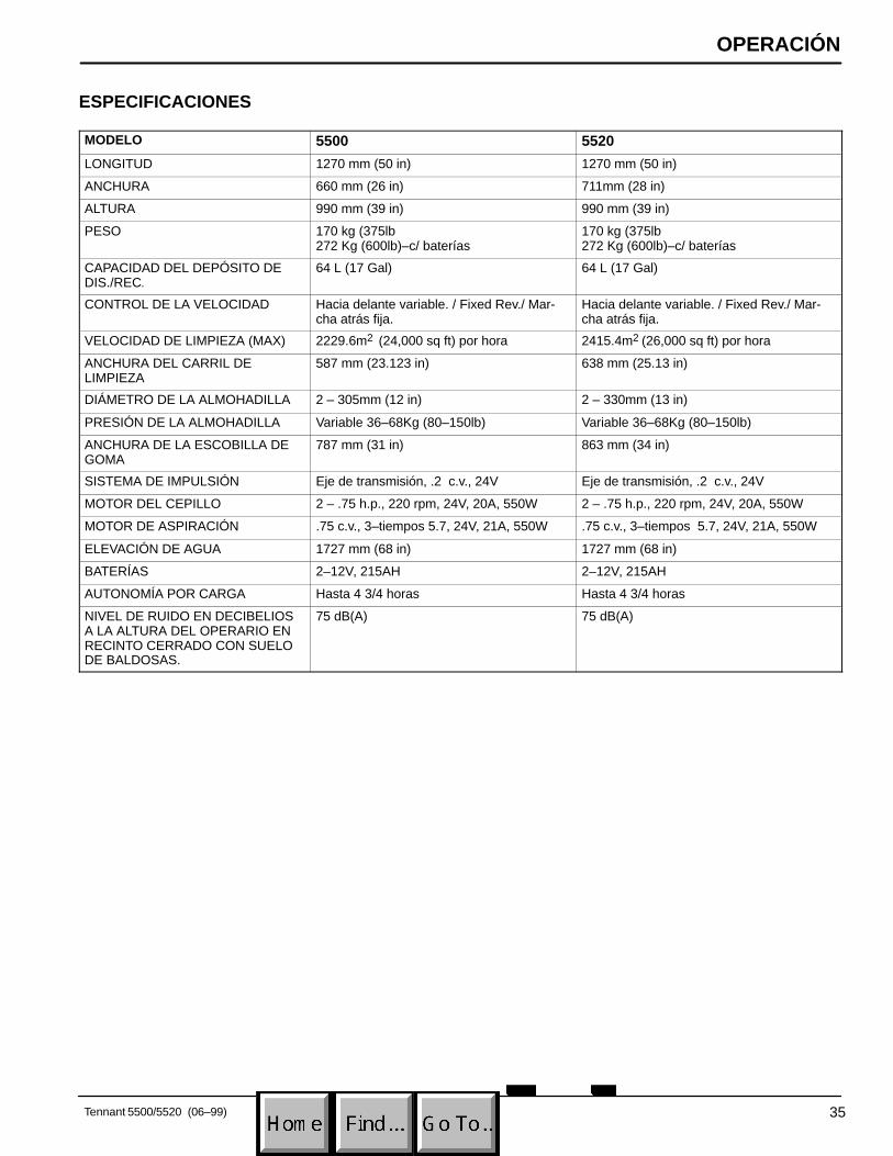
ESPECIFICACIONES
MODELO 5500 5520
LONGITUD 1270 mm (50 in) 1270 mm (50 in)
ANCHURA 660 mm (26 in) 711mm (28 in)
ALTURA 990 mm (39 in) 990 mm (39 in)
PESO 170 kg (375lb 272 Kg (600lb)–c/ baterías
170 kg (375lb 272 Kg (600lb)–c/ baterías
CAPACIDAD DEL DEPÓSITO DEDIS./REC.
64 L (17 Gal) 64 L (17 Gal)
CONTROL DE LA VELOCIDAD Hacia delante variable. / Fixed Rev./ Mar-cha atrás fija.
Hacia delante variable. / Fixed Rev./ Mar-cha atrás fija.
VELOCIDAD DE LIMPIEZA (MAX) 2229.6m2 (24,000 sq ft) por hora 2415.4m2 (26,000 sq ft) por hora
ANCHURA DEL CARRIL DE LIMPIEZA
587 mm (23.123 in) 638 mm (25.13 in)
DIÁMETRO DE LA ALMOHADILLA 2 – 305mm (12 in) 2 – 330mm (13 in)
PRESIÓN DE LA ALMOHADILLA Variable 36–68Kg (80–150lb) Variable 36–68Kg (80–150lb)
ANCHURA DE LA ESCOBILLA DEGOMA
787 mm (31 in) 863 mm (34 in)
SISTEMA DE IMPULSIÓN Eje de transmisión, .2 c.v., 24V Eje de transmisión, .2 c.v., 24V
MOTOR DEL CEPILLO 2 – .75 h.p., 220 rpm, 24V, 20A, 550W 2 – .75 h.p., 220 rpm, 24V, 20A, 550W
MOTOR DE ASPIRACIÓN .75 c.v., 3–tiempos 5.7, 24V, 21A, 550W .75 c.v., 3–tiempos 5.7, 24V, 21A, 550W
ELEVACIÓN DE AGUA 1727 mm (68 in) 1727 mm (68 in)
BATERÍAS 2–12V, 215AH 2–12V, 215AH
AUTONOMÍA POR CARGA Hasta 4 3/4 horas Hasta 4 3/4 horas
NIVEL DE RUIDO EN DECIBELIOSA LA ALTURA DEL OPERARIO ENRECINTO CERRADO CON SUELODE BALDOSAS.
75 dB(A) 75 dB(A)
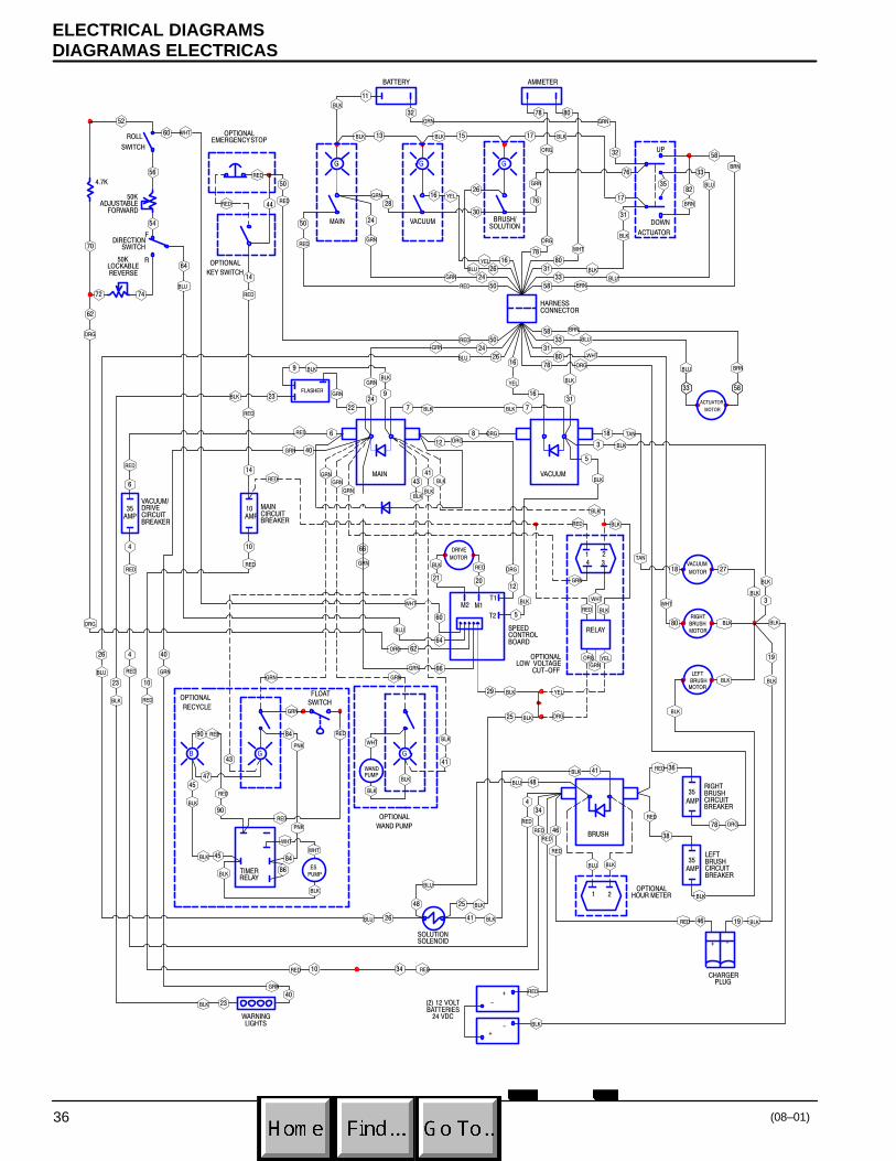
ELECTRICAL DIAGRAMSDIAGRAMAS ELECTRICAS
(08–01)36
�
�������
�� �
��
��
�
��
�
���
��
��
��
��
�
� ��
�
�
�
�
�
�
��
��
��
��
��
��
��
�
�
�
�
�
�
��
��
��
��
��
�
�� �� ��
���
���
��
��
�
��
��
��
��
���
�
��
�
�
�
�
�
�
�
��
� �
�
�
�
��
�
�
��
��
��
���
��
��
�� ��
��
���
������
� ��
�� ��
���
��
��� ��
��
���
���
���
���
������
�
��
���
������
���
���
���
��
��
���
���
��
���
��
�
��
��
��
�
�
��
��
��
�� ��
�
����
�
��
���
��
�� ��
�
��
�
�
��
��
��
�
��
��
��
���
��
��
���
���
���
��� ��
��
��� ���
���
���
���
���
��
��
��
��
���
���
���
���
��
���
��
��
��
��
��
��
��
��
��
��
�� ���
���
���
���
���
�� ��
��
���
���
��
��
���
�� ��
��
���
���
�� ��
���
���
���
��
���
���
���
���
���
��
��
���
��
��
���
���
���
���
������
���
���
��� ���
��� ��
��
��
��
��
�� �� ��
��
���
���
��
���
��
���
���
������
���
���
���
��
���
���
��
�
�
��
�
���
���
��
���
��
���
�� ���
����
��������
�����
�����
������
�
�
�����
��� ���
�����
�����
��������
�
����
������
�����
�����
�� �
�����
����
�� ������
��
���
�����
�
!
!"
"
! "
��
��������
����
������
�����������������# ���
��������
���# �����
�$��
�����%� �� ���������
��������� �����
�
��������� ������� �
����
�����
�����������##�������
���"���
����������
��������
�������
��������
����#����
�����
�����
������������#�����
&'#�#���� ������� �#���
������ �� �( �������
����������� ����
�����
������� �������
������������
����� ���������
������(������������ ������
����������� ������
����� �� �������� ������
���� �� �������� ������
�����������
�
� �
���� ������
�� �
� �

ELECTRICAL DIAGRAMSDIAGRAMAS ELECTRICAS
37 (8–01)
# ������
�
�
�
�
� �
��������
����
��
"��"
���
"��"
���
"��"
���
"��"
���
��� ��
"��"##" ��"
"��"##" ��"
"�"
���
"�"##���
"�"##"���"
"��"#"���"
"�"
"���"
"���"##"�"
"�"# " ��"
"�"#"���"
"�"
" ��"
"��"
"���"
"�"#"���"
"��"
"���"
"��"
"���"
"�"
"���"
"�"
"���"
"��"# "���"
"��"# " ��"
"�"
" ��"
""#"���"
"��"#"���"
"�"# " ��"
"�"#" ��"
""#"���"
""#"���"
"��"
���
"�"#" ��"
"�"
"���""�"
" ��"
"��"# " ��"
"��"
"���"
"�"
" ��"
" ��" " ��"
"�"# " ��"
"�"# " ��"
""#"���" " ��"
" ��""�"
"���"
"�"# "���""�"
"���"
"��"
"���"
" ��"
"���"
"���"
"���"
"�"#"���"
"��"#"���"
"���"
"��"# " ��"
" ��"
"��"# " ��"
"��"# " ��"
"���" "��"# " ��"
" ��""���"
�
�
"���"
"���" "���"
"���"
" ��"
" ��"
"���"
"���"
"���" "�"
"�"
"�"
"�"
� ��
��
�
"��"
"���"
"�"#" ��"
"��"
"���"
"�"
" ��"
"��"" ��"
"�"#" ��"
"��"# " ��"
"��"# " ��"
"��"# " ��"
"�"
"��"# " ��"
�����
�����
������
�����
���
���
����
"!
"!
&'#�#����# ������� �#���
�
�
���
���
����������
����� ����
���� �����
�$��
������
���
�����
��� ���
�������
�����
)������)
�� �
�������
������� �������
) �� �)
���
���
�������
����� �� �
�����
���� �� �
�����
)����)
���������
����� �����
�������
����
���� ��
���#�������#���#���������
�$�$
��������
�����
����
��������
��������
������(������������# ������
���� �����
�����������������
����# �� ��������# ������
�����# �� ��������# ������
�� ����������

PARTS LISTLISTA DE PIEZAS
Tennant 5500/5520 (08–01)38
REPLACEMENT BRUSHES AND PAD DRIVER GROUPCEPILLO DEL REEMPLAZO Y GRUPO DEL MANDO DE LA ALMOHADILLA
�
�
�
�
�

PARTS LISTLISTA DE PIEZAS
Tennant 5500/5520 (08–01) 39
REPLACEMENT BRUSHES AND PAD DRIVER GROUPCEPILLO DEL REEMPLAZO Y GRUPO DEL MANDO DE LA ALMOHADILLA
REF PART # DESCRIPTION QTY.
∇ 1 240260 �BRUSH, POLY–SCRUB2/PK 305MM (12”)
2
603159 �BRUSH, POLY–SCRUB 2/PK 330MM (13”)
2
240261 �BRUSH, DYNA–SCRUB 2/PK 305MM (12”)
2
603160 �BRUSH, DYNA–SCRUB 2/PK 330MM (13”)
2
240259 �BRUSH, STRATA SCRUB/STRIP2/PK 305MM (12”)
2
603161 �BRUSH, STRATA SCRUB/STRIP 2/PK 330MM (13”)
2
� 2 240238 �LUGS, W/ SCREWS (SET OF 3) 6
� 3 100106 �PLATE, PAD DRIVER BASE 2
∇ � �� ��#(#���%����
� ��������#��#� �� ��#(#��������#��#��#���%����
� �����������# ����#���� #(#�������� #�����������
REF PART # DESCRIPTION QTY.
∇ 4 240262 �ASM., PAD DRIVER 2/PK 305MM (12”)
2
602928 �ASM., PAD DRIVER 2/PK 330MM (13”)
2
� 5 240238 �LUGS, W/SCREWS (SET OF 3) 6
� 6 100106 �PLATE, PAD DRIVER BASE 2
� 7 100107 �RING, PAD RETAINER SNAP–IN 2

PARTS LISTLISTA DE PIEZAS
Tennant 5500/5520 (08–01)40
SOLUTION TANK GROUPGRUPE DEL DEPÓSITO DE DISOLUCIÓN
��
�
�
�
�
����
�� ��
��
�
�
��
����
����
��
��
�
��
� �
��
��
��
��
��
��
��
�
�
��
����
��
�
�
�

PARTS LISTLISTA DE PIEZAS
Tennant 5500/5520 (8–01) 41
SOLUTION TANK GROUPGRUPE DEL DEPÓSITO DE DISOLUCIÓN
REF PART # DESCRIPTION QTY.
∇ 1 607982 ASM., SOL. TANK COVER TEAL 1
� 2 607515 COVER, TANK TEAL 1
� 3 140706 RIVET, POP 7
� 4 611068 HINGE, COVER 1
5 603233 DECAL, BATTERY RECHARGE 1
6 630010 �GASKET, TUBE ADAPTER 1
7 630011 TUBE, VAC 1
8 630267 SPRING, TUBE ADAPTER 1
9 150529 HOSE BARB 2
10 608706 BRACKET, VAC TUBE 1
11 140027 WASHER, FLAT 3
12 140015 WASHER, LOCK 3
13 200031488 SCREW, M8X1.25X20MM 2
14 600476 �STRAP, PLUG REAR FILL 1
15 140011 WASHER, FLAT 1
16 140350 SCREW, #10X1/2 1
17 200031488 SCREW, M8X1.25X20MM 1
18 230925 SUPPORT, RECOVERY TANK 1
19 611418 BUSHING 1
20 140032 WASHER, FLAT 2
∇ � �� ��#(#���%����
� ��������#��#� �� ��#(#��������#��#��#���%����
� �����������# ����#���� #(#�������� #����������� #����####��������#��#�*� ������
REF PART # DESCRIPTION QTY.
21 600650 DECAL, SQUEEGEE LEVER CE 1
22 607552 TANK, SOLUTION TEAL 1
23 607983 ASM., DRAIN HOSE W/LEVEL IND. 1
24 602529 �SCREEN, FILL 1
25 608915 CLAMP, HOSE 2–WIRE 1
26 621324 �PLUG, EXPANSION 1
27 608118 DECAL, ”5500” 2
608119 DECAL, ”5520” 2
28 630002 �CASTER, 4” 2
29 140036 WASHER, 3/8 FLAT 8
30 140333 WASHER, M10 SPLITLOCK 8
31 140277 SCREW, M10X1.5X20MM 8
32 578141000 SCREW, M5X10MM 2
33 140018 WASHER, #10 INT 2
34 600298 SHIELD, LIGHT 1
35 606242 GASKET, 30” 1
36 130023 LIGHT, SAFETY 1
37 120192 DECAL, TENNANT LOGO 1
38 3701.6 SCREW, #6X3/4 2

PARTS LISTLISTA DE PIEZAS
Tennant 5500/5520 (08–01)42
RECOVERY TANK GROUPCONJUNTO DEPOSITO RECUPERAR
�
��
��
�
�
�
��
�
��
���
��
�
��
��
�
��
��
��
��
���
��
��
�
�
��
��
��
��
��
��
��
��
��
�
�
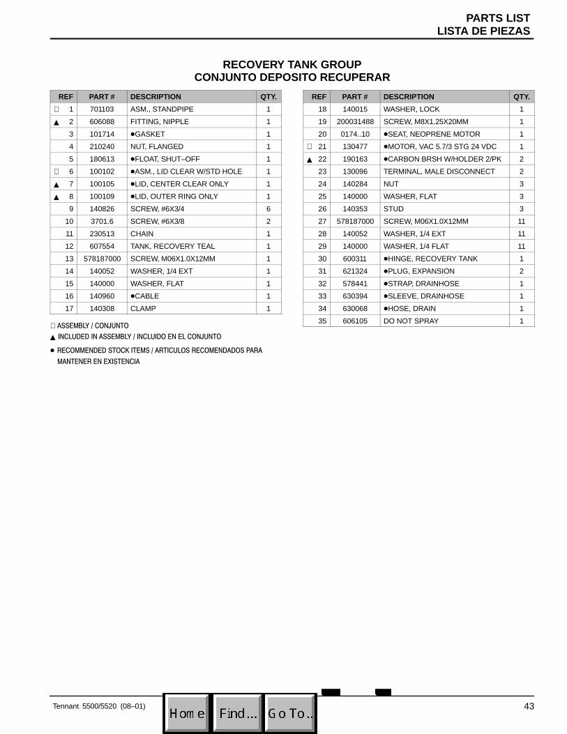
PARTS LISTLISTA DE PIEZAS
Tennant 5500/5520 (08–01) 43
RECOVERY TANK GROUPCONJUNTO DEPOSITO RECUPERAR
REF PART # DESCRIPTION QTY.
∇ 1 701103 ASM., STANDPIPE 1
� 2 606088 FITTING, NIPPLE 1
3 101714 �GASKET 1
4 210240 NUT, FLANGED 1
5 180613 �FLOAT, SHUT–OFF 1
∇ 6 100102 �ASM., LID CLEAR W/STD HOLE 1
� 7 100105 �LID, CENTER CLEAR ONLY 1
� 8 100109 �LID, OUTER RING ONLY 1
9 140826 SCREW, #6X3/4 6
10 3701.6 SCREW, #6X3/8 2
11 230513 CHAIN 1
12 607554 TANK, RECOVERY TEAL 1
13 578187000 SCREW, M06X1.0X12MM 1
14 140052 WASHER, 1/4 EXT 1
15 140000 WASHER, FLAT 1
16 140960 �CABLE 1
17 140308 CLAMP 1
∇ � �� ��#(#���%����
� ��������#��#� �� ��#(#��������#��#��#���%����
� �����������# ����#���� #(#�������� #����������� #����####��������#��#�*� ������
REF PART # DESCRIPTION QTY.
18 140015 WASHER, LOCK 1
19 200031488 SCREW, M8X1.25X20MM 1
20 0174..10 �SEAT, NEOPRENE MOTOR 1
∇ 21 130477 �MOTOR, VAC 5.7/3 STG 24 VDC 1
� 22 190163 �CARBON BRSH W/HOLDER 2/PK 2
23 130096 TERMINAL, MALE DISCONNECT 2
24 140284 NUT 3
25 140000 WASHER, FLAT 3
26 140353 STUD 3
27 578187000 SCREW, M06X1.0X12MM 11
28 140052 WASHER, 1/4 EXT 11
29 140000 WASHER, 1/4 FLAT 11
30 600311 �HINGE, RECOVERY TANK 1
31 621324 �PLUG, EXPANSION 2
32 578441 �STRAP, DRAINHOSE 1
33 630394 �SLEEVE, DRAINHOSE 1
34 630068 �HOSE, DRAIN 1
35 606105 DO NOT SPRAY 1

PARTS LISTLISTA DE PIEZAS
Tennant 5500/5520 (08–01)44
CONSOLE GROUPCONJUNTO CONSOLA DE CONTROLES
��
�
�
�
�
�
�
�
��
��
��
��
��
��
�
�
��
�
��
��
��
��
�
��
�
��
��
��
�
��
�
����
����
��
��
�
��
��
��
��
��
��
�
��
��
��
�
��
�
��
�
�
�
�
�
�

PARTS LISTLISTA DE PIEZAS
Tennant 5500/5520 (08–01) 45
CONSOLE GROUPCONJUNTO CONSOLA DE CONTROLES
REF PART # DESCRIPTION QTY.
1 200823 �GRIP, HANDLE TUBE 2
2 605351 BUSHING 1
3 604402 HANDLE, TUBE 1
4 606857 �GAUGE, BRUSH PRESSURE 1
5 578141000 SCREW, M5X10MM 8
6 140018 WASHER, LOCK 8
7 602560 PANEL, SWITCH 1
8 603399 �SWITCH, MOM. ON/OFF/MOM. ON 1
9 601107 �SWITCH, LIGHTED ROCKER 3
10 606020 �METER, BATTERY VOLTAGE 24V 1
11 630104 �SPEED CONTROL, PMB 55 AMP 1
12 200160014 NUT 4
13 630261 SPACER 2
14 630128 HEATSINK, ALLUM. 1
15 607556 HOUSING, CONTROL TEAL 1
16 601108 �SWITCH, TOGGLE 1
17 130753 �BOOT, SWITCH 1
18 130776 �POTIENTIOMETER, 50K 1
19 130775 �POTIENTIOMETER, 50K LOCKABLE
1
20 140351 SCREW, M12X1.75X70MM 2
21 630304 SCREW, M4X35MM 2
22 230715 TUBE, HANDLE ADJUSTMENT 1
23 230649 PIN, HANDLE ADJUSTMENT 2
24 230710 PIN, HANDLE LOCK 2
25 140415 SPRING, LOCK PIN 1
26 140155 BUSHING 2
27 606550 �KNOB, SPEED CONTROL 1
28 603007 BUSHING, SNAP 1
29 602886 PIN, SPRING RETURN 1
� �����������# ����#���� #(#�������� #����������� #����####��������#��#�*� ������
REF PART # DESCRIPTION QTY.
30 605812 SPRING, EXTENSION 1
31 140829 SCREW, 6–32X1 2
32 140019 WASHER, LOCK 2
33 27098 BRACKET, SWITCH 1
34 130729 �SWITCH, ROLL 1
35 140552 NUT 1
36 140000 WASHER, FLAT 2
37 25671 MOUNT, SWITCH 1
38 140890 SCREW, 10–24X1/2 1
39 140900 SCREW, 10–24X3/4 TRSPHL 2
40 608322 SCREW, M6X1.0X16 2
41 140284 NUT, M6X1.0 NYLOCK 2
42 140045 WASHER, FLAT 2
43 140024 WASHER, LOCK 2
44 603830 PLATE, GUARD SWITCH 1
45 140540 NUT, 6–32 HEX 2
46 630343 CLAMP, CABLE 1
47 140552 NUT, 10–24 NYLOCK 1
48 605094 COLLAR, HANDLE 2
49 140859 SCREW, 1/4 SK CUP 2
50 606549 DECAL, SPEED CONTROL 1
51 602641 BRACKET, DRAIN HOSE 1
52 230661 PLATE, LOCK CONTROL HSG. 1
53 140027 WASHER, FLAT 2
54 140015 WASHER, LOCK 2
55 200031488 SCREW, M8X1.25X20 2
N/S 602873 HARNESS CONSOLE W/POT. 1
606093 HARNESS, MAIN/SWITCH/CONSOLE
1

PARTS LISTLISTA DE PIEZAS
Tennant 5500/5520 (08–01)46
ELECTRICAL / BATTERY GROUPGRUPO DEL ELÉCTRICO/BATERÍA
�
�
�
�
�
��
�
��
�
��
��
��
��
��
��
�
��
���
�
�
��
��
�
�
���
��
��
��
��
�
�
��
��
��
�
��
�� �
��
��
��
�
�
��
��
��
��
�� ��
��
��
��
��
����
��
��
��
��

PARTS LISTLISTA DE PIEZAS
Tennant 5500/5520 (08–01) 47
ELECTRICAL / BATTERY GROUPGRUPO DEL ELÉCTRICO/BATERÍA
REF PART # DESCRIPTION QTY.
1 602559 PANEL, CONTROL HOUSING 1
2 609969 �PLUG, HOUR METER 2
3 069764626 �PLUG, HOLE 012.7 1
4 130161 �PLUG, DOME .850 1
5 130175 �PLUG, DOME .750 1
6 120649 DECAL, WARNING BATTERY 1
7 582150 �PLUG, ACCESSORY SWITCH 2
8 608322 SCREW, M6X1.0X16 6
9 140284 NUT, M6X1.O NYLOCK 6
10 140000 WASHER, FLAT 7
11 606404 �ASM., DIODE W/RING TERM. 3
12 281001009 RING, TERMINAL #10 6
13 605905 �SOLENOID, 24V 3
14 130021 �FLASHER, 24VDC 1
15 606243 TAPE, ACRYLIC 1”X.25’ 1
16 130737 �BREAKER, CIRCUIT BRSH 10AMP 1
17 602951 �BREAKER, CIRCUIT 35 AMP 3
18 140829 SCREW, 6–32X1 2
19 140019 WASHER, #6 EXT 2
20 605387 �CONNECTOR, 50A W/O CNTCTS 1
21 578141000 SCREW, M5X10 2
� �����������# ����#���� #(#�������� #����������� #����####��������#��#�*� ������
REF PART # DESCRIPTION QTY.
22 140018 WASHER, #10 INT 2
23 130698 BUSHING, SNAP 1
24 602887 BRACKET 1
25 140553 SCREW, 1/4–20X1/2 2
26 140016 WASHER, LOCK 1
27 602871 CABLE, BATTERY #6 BLACKX20” 1
28 578427 �STANDOFF 1
29 602872 CABLE, BATTERY #6 REDX28” 1
30 603235 CHARGER, 24DC 20 AMP 1
31 601991 TRAY, BATTERY 1
32 600394 BATTERY, 12V 215A 2
33 130364 �CABLE, BATTERY #6 BLACKX15” 1
34 140539 NUT, 6–32 KEP 2
35 605823 �O–RING .929 ID X .996 OD 1
36 603331 SPACER, CHARGER PLUG 1
37 578729 DECAL, READ MANUAL 1
38 604486 ASM., DIODE SPLICED 1
39 611221 BOOT, BATTERY CABLE BLK 2
40 611222 BOOT, BATTERY CABLE RED 2
41 45962 COVER, BATTERY TERMINAL 4

PARTS LISTLISTA DE PIEZAS
Tennant 5500/5520 (08–01)48
DRIVE GROUPGRUPO DE TRANMISIÓN
��
�
�
��
��
��
�
��
��
��
��
��
��
��
��
��
��
�
��
��
��
��
��
��
��
��
��
��
��
��
�
��
��
�
�
�
�
�
�
��
��
��
��
�
��
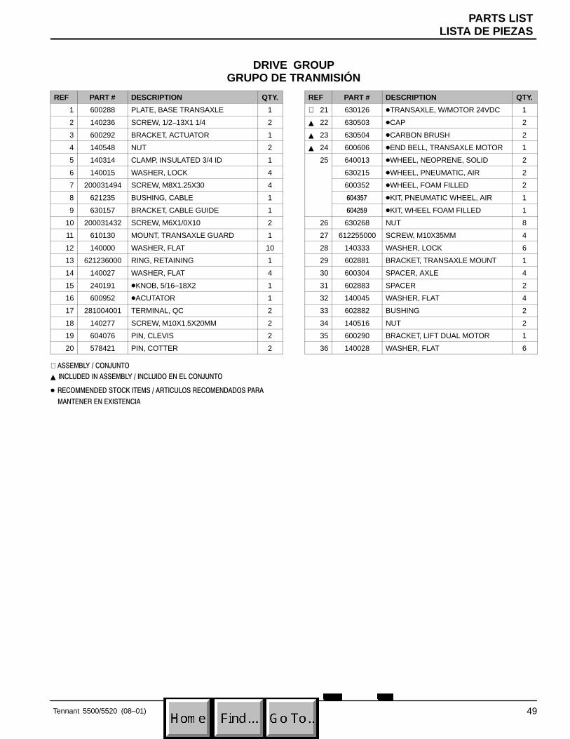
PARTS LISTLISTA DE PIEZAS
Tennant 5500/5520 (08–01) 49
DRIVE GROUPGRUPO DE TRANMISIÓN
REF PART # DESCRIPTION QTY.
1 600288 PLATE, BASE TRANSAXLE 1
2 140236 SCREW, 1/2–13X1 1/4 2
3 600292 BRACKET, ACTUATOR 1
4 140548 NUT 2
5 140314 CLAMP, INSULATED 3/4 ID 1
6 140015 WASHER, LOCK 4
7 200031494 SCREW, M8X1.25X30 4
8 621235 BUSHING, CABLE 1
9 630157 BRACKET, CABLE GUIDE 1
10 200031432 SCREW, M6X1/0X10 2
11 610130 MOUNT, TRANSAXLE GUARD 1
12 140000 WASHER, FLAT 10
13 621236000 RING, RETAINING 1
14 140027 WASHER, FLAT 4
15 240191 �KNOB, 5/16–18X2 1
16 600952 �ACUTATOR 1
17 281004001 TERMINAL, QC 2
18 140277 SCREW, M10X1.5X20MM 2
19 604076 PIN, CLEVIS 2
20 578421 PIN, COTTER 2
∇ � �� ��#(#���%����
� ��������#��#� �� ��#(#��������#��#��#���%����
� �����������# ����#���� #(#�������� #����������� #����####��������#��#�*� ������
REF PART # DESCRIPTION QTY.
∇ 21 630126 �TRANSAXLE, W/MOTOR 24VDC 1
� 22 630503 �CAP 2
� 23 630504 �CARBON BRUSH 2
� 24 600606 �END BELL, TRANSAXLE MOTOR 1
25 640013 �WHEEL, NEOPRENE, SOLID 2
630215 �WHEEL, PNEUMATIC, AIR 2
600352 �WHEEL, FOAM FILLED 2
������ �KIT, PNEUMATIC WHEEL, AIR 1
����� �KIT, WHEEL FOAM FILLED 1
26 630268 NUT 8
27 612255000 SCREW, M10X35MM 4
28 140333 WASHER, LOCK 6
29 602881 BRACKET, TRANSAXLE MOUNT 1
30 600304 SPACER, AXLE 4
31 602883 SPACER 2
32 140045 WASHER, FLAT 4
33 602882 BUSHING 2
34 140516 NUT 2
35 600290 BRACKET, LIFT DUAL MOTOR 1
36 140028 WASHER, FLAT 6

PARTS LISTLISTA DE PIEZAS
Tennant 5500/5520 (08–01)50
BRUSH GROUPCONJUNTO IMPULSO DE CEPILLO
��
�
�
��
�
��
�
���
��
��
��
��
��
�
�
��
��
��
��
��
��
��
�
�
��
��
��
��
��
��
�
�
�
�
�

PARTS LISTLISTA DE PIEZAS
Tennant 5500/5520 (08–01) 51
BRUSH GROUPCONJUNTO IMPULSO DE CEPILLO
REF PART # DESCRIPTION QTY.
∇ 1 130491 �MOTOR & GEAR BOX, BRUSH 2
�2 630609 �ASM., GEAR BOX 1
�2 190741 �ASM., BRUSH CARD 1
�2 190970 �BRUSH, CARBON 4
�2 140632 �KEY, 1/4X1 1
� 2 281001014 TERMINAL RING (NEG) LT MOTOR 1�
281001014 TERMINAL RING (NEG) RT MOTOR 1
� 3 130109 TERMINAL RING (POS) LT MOTOR 1�
130109 TERMINAL RING (POS) RT MOTOR 1
4 100764 COVER, BRUSH MOTOR 2
5 600300 PLATE, GUIDE 2
6 140003 WASHER, FENDER 8
7 140016 WASHER, LOCK 4
8 140272 SCREW, M6X1.0X16MM 4
9 140618 PIN, ROLL 4
10 140028 WASHER, FLAT 8
11 140017 WASHER, LOCK 8
12 140202 SCREW, 3/8–16X1 8
13 606335 PLATE, DRIVER NYLON 2
14 25732 WASHER, FLAT 4
15 140016 WASHER, LOCK 4
∇ � �� ��#(#���%����
� ��������#��#� �� ��#(#��������#��#��#���%����
� �����������# ����#���� #(#�������� #����������� #����####��������#��#�*� ������
REF PART # DESCRIPTION QTY.
16 140219 SCREW, 5/16–18X1 2
17 140417 �CLIP, SPRING 2
18 230651 �CLAMP, BRUSH PLATE 2
19 140018 WASHER, LOCK 8
20 230697 �STOP, DRIVER RELEASE 2
21 606915 SCREW, HIGH LOW 10–16X3/8 8
22 200031488 SCREW, M08X1.25X20MM 4
23 140015 WASHER, LOCK 4
24 140272 SCREW, 1/2–13X3 1
25 140016 WASHER, LOCK 1
26 600299 SKIRT, FRONT LIP 1
27 600289 BRACKET, MOTOR MOUNT 1
28 602558 BRACKET, SPRING MOUNT 1
29 602930 BUSHING 1
30 578298000 WASHER, FLAT 8
31 602555 SPRING 1
32 600200 NUT 1
33 140028 WASHER, FLAT 2
34 602556 BRACKET, SPRING 1
35 140225 SCREW, 3/8–16X2 1
36 100058 TAPE, ACRYLIC 1”X.50’ 1

PARTS LISTLISTA DE PIEZAS
Tennant 5500/5520 (08–01)52
BRUSH SKIRT GROUPCONJUNTO JUEGO DE CEPILLO
��
��
�
�
��
�
�
��
�
�
�
�
���
��
��
�
��
��
��
��
�
��
��
��
�
��
�
�
��
����
��

PARTS LISTLISTA DE PIEZAS
Tennant 5500/5520 (08–01) 53
BRUSH SKIRT GROUPCONJUNTO JUEGO DE CEPILLO
REF PART # DESCRIPTION QTY.
∇ 609798 ASM., SKIRT OPERATOR LH TEAL (5500)
1
609796 ASM., SKIRT OPERATOR LH TEAL (5520)
1
609797 ASM., SKIRT OPERATOR RH TEAL (5500)
1
609795 ASM., SKIRT OPERATOR RH TEAL (5520)
1
� 1 607558 SKIRT, OPERATOR LH TEAL (5500)
1
607564 SKIRT, OPERATOR LH TEAL (5520)
1
607560 SKIRT, OPERATOR RH TEAL (5500)
1
607566 SKIRT, OPERATOR RH TEAL (5520)
1
� 2 603154 �SCREW, M08X1.25X40MM 2
� 3 578144000 SCREW, M5X16MM 10
� 4 630450 �WHEEL, RUBBER 2
� 5 140283 NUT 6
� 6 600301 BRACKET, SKIRT MOUNT 2
� 7 140027 WASHER, 5/16 FLAT 4
∇ � �� ��#(#���%����
� ��������#��#� �� ��#(#��������#��#��#���%����
� �����������# ����#���� #(#�������� #����������� #����####��������#��#�*� ������
REF PART # DESCRIPTION QTY.
� 8 140015 WASHER, 5/16 SPLITLOCK 4
� 9 578237000 SCREW, M8X18 4
� 10 140932 �LATCH, HOOD 1
� 11 200070340 SCREW, M4X.7X8MM 4
� 12 140023 WASHER, #8 INT 4
600295 �GUARD, SPLASH (5500) 2
600294 �GUARD, SPLASH (5520) 2
600297 STRAP, SPLASH GUARD (5500) 2
600296 STRAP, SPLASH GUARD (5520) 2
� 15 140011 WASHER, FLAT 22
� 16 140018 WASHER, LOCK 16
� 17 140293 SCREW, M5X0.8X30MM 6
18 575029000 SCREW, M8X1.25X20 4
19 140015 WASHER, 5/16 SPLITLOCK 4
20 140000 WASHER, 1/4 FLAT 4
21 230943 �PIN, SKIRT 2
22 607951 BRACKET, SKIRT MOUNT LH 1
23 607952 BRACKET, SKIRT MOUNT RH 1
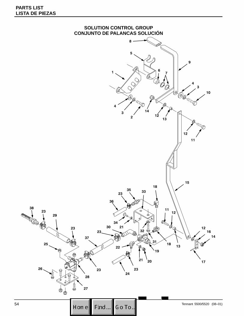
PARTS LISTLISTA DE PIEZAS
Tennant 5500/5520 (08–01)54
SOLUTION CONTROL GROUPCONJUNTO DE PALANCAS SOLUCIÓN
�
��
�
�
�
�
�
�
�
��
�
��
��
��
�
��
��
��
���
��
�
��
��
����
��
��
��
��
��
��
��
��
��
����
��
��
�
�
��
��
��
��
��
�
��
��
��
��

PARTS LISTLISTA DE PIEZAS
Tennant 5500/5520 (08–01) 55
SOLUTION CONTROL GROUPCONJUNTO DE PALANCAS SOLUCIÓN
REF PART # DESCRIPTION QTY.
1 230661 PLATE, LOCK CONTROL HSG 1
2 200031488 SCREW, M8X1.25X20MM 1
3 140015 WASHER, LOCK 2
4 140027 WASHER, FLAT 2
5 602641 BRACKET, DRAIN HOSE HANGER 1
6 230735 BUSHING 2
7 140060 WASHER, WAVE 2
8 200816 �GRIP, HANDLE 1
9 602884 HANDLE, SOLUTION VALVE 1
10 200031496 SCREW, M8X1.25X35 1
11 140208 SCREW, 1/4–20X1 2
12 140000 WASHER, FLAT 4
13 140134 BUSHING 2
14 140501 NUT 2
15 230718 LEVER, SOLUTION VALVE 1
16 230657 ARM, VALVE 1
17 140616 PIN, ROLL 1
18 150406 ELBOW, STREET 1/4 90� 2
19 210259 �VALVE, 3–WAY 5/16 PORTS 1
20 140283 NUT 2
� �����������# ����#���� #(#�������� #����������� #����####��������#��#�*� ������
REF PART # DESCRIPTION QTY.
21 140011 WASHER, FLAT 4
22 605394 HOSE BARB 1
23 140310 CLAMP 4
24 606239 TUBING, 3/8IDX25” 1
25 140284 NUT, M6X1.0 NYLOCK 2
26 140272 SCREW, M6X1.0X16MM 4
27 602879 PLATE, SOLENOID MOUNT 1
28 603310 �VALVE, SOLENOID 24 VDC 1
29 605100 TUBING, 5/8X2” 1
30 150409 ELBOW, 1/4X5/8 90� 1
31 140272 SCREW, M06X1.0X16MM 2
32 140016 WASHER, LOCK 2
33 600303 BRACKET, VALVE 1
34 578144000 SCREW, M5X16MM 2
35 150516 HOSE BARB 1
36 606239 TUBING, 3/8IDX25” 1
37 605099 TUBING, 5/8IDX3” 1
38 602929 �FILTER, SOLUTION TANK 1
39 607775 CLAMP, HOSE 2 WIRE BLK 2

PARTS LISTLISTA DE PIEZAS
Tennant 5500/5520 (08–01)56
SQUEEGEE CONTROL GROUPCONJUNTO DE PALETA PLANCAS
��
�
�
�
�
�
�
�
�
��
��
�
��
��
��
��
��
��
��
��
��
���
�
��
�
���
��

PARTS LISTLISTA DE PIEZAS
Tennant 5500/5520 (08–01) 57
SQUEEGEE CONTROL GROUPCONJUNTO DE PALETA PLANCAS
REF PART # DESCRIPTION QTY.
1 160613 �HOSE, VAC 1.5X30” W/CUFFS 1
2 630156 �CABLE, SQUEEGEE LIFT 1
3 140501 NUT 2
4 140236 SCREW, 1/2–13X1–1/4” 2
5 140024 WASHER, LOCK 2
6 140045 WASHER, FLAT 6
7 140139 BUSHING 2
8 140516 NUT, 1/2–13 NYLOCK 1
9 600293 PIVOT, SQUEEGEE MOUNT 1
10 230730.BK BRACKET, SQUEEGEE MOUNT 1
11 140509 NUT, 1/2–13 JAM 2
12 602981 SCREW, 1/2–13X5–1/2” 1
13 605361 �KNOB, 5/16–18 2
14 140284 NUT 2
� �����������# ����#���� #(#�������� #����������� #����####��������#��#�*� ������
REF PART # DESCRIPTION QTY.
15 140272 SCREW, M6X1.0X16MM 2
16 602880 PLATE, SQUEEGEE CABLE LINK 1
17 200 031 496 SCREW, M08X35 1
18 140015 WASHER, LOCK 2
19 140027 WASHER, FLAT 2
20 602885 HANDLE, SQUEEGEE LIFT 1
21 200816 �GRIP, HANDLE 1
22 604358 BUSHING SPACER 1
23 230661 PLATE, LOCK CONTROL HSG. 1
24 200031488 SCREW, M8X1.25X20MM 1
25 140268 SCREW, M5X.8X12MM 2
26 140031 WASHER, LOCK 2
27 230712 PLATE, SQUEEGEE LOCK 1

PARTS LISTLISTA DE PIEZAS
Tennant 5500/5520 (08–01)58
CURVED SQUEEGEE GROUP CONJUNTO PALETA
�
�
�
���
�
�
�
�
��
��
��
��
��

PARTS LISTLISTA DE PIEZAS
Tennant 5500/5520 (08–01) 59
CURVED SQUEEGEE GROUPCONJUNTO PALETA
REF PART # DESCRIPTION QTY.
∇ 603262 ASM., SQUEEGEE CURVED (5500) 1
603263 ASM., SQUEEGEE CURVED (5520) 1
� 1 140799 SCREW, 5/16–18X1–1/2 2
� 2 630450 WHEEL, RUBBER 2
� 3 602958 WELDMENT, SQUEEGEE (5500) 1�
602960 WELDMENT, SQUEEGEE (5520) 1
� 4 605361 �KNOB, BLACK 2
� 5 603260 GASKET, SQUEEGEE CURVED 1
� 6 140221 SCREW, 5/16–18X1–1/4 2
� 7 140226 SCREW, 5/16–18X5/8 2
� �� ��
� ��������#��#� �� ��
� �����������# ����#����
REF PART # DESCRIPTION QTY.
� 8 140015 WASHER, 5/16 SPLITLOCK 2
� 9 605975 SCREW, 10–24X1/2” 24-28
� 10 602962 PLATE, SQG RETAINING (5500) 2�
602963 PLATE, SQG RETAINING (5520) 2
� 11 603660 �BLADE, SQUEEGEE 31” (5500) 2�
603661 �BLADE, SQUEEGEE 34” (5520) 2
∇ � 700844 �ASM., SQUEEGEE ROLLER 2
� 12 230474 BRACKET, SQUEEGEE ROLLER 2
� 13 605317 ROLLER 2
� 14 140710 RIVET, AXLE 3/8X1.6 2

OPTIONSOPCIONES
60 Tennant 5500/5520 (08–01)
ES� KITES� JUEGO
1
3
12
4
5
6
7
8
9
10
11
12
1314
1315
13
16

OPTIONSOPCIONES
61Tennant 5500/5520 (08–01)
ES� KITES� JUEGO
REF PART # DESCRIPTION QTY.
∇ 604780 �KIT, ES� 1
� 1 630419 �SWITCH, ROCKER 1
� 2 578720 �SPLASHGUARD, RCKR SWITCH 1
� 3 130738 �LIGHT, INDICATOR GREEN 1
� 4 140283 NUT 1
� 5 630145 �TIMER, 24VDC, RANGE:30SEC 1
� 6 578008000 SCREW 1
� 7 603166 �SWITCH, LIQUID LEVEL W/NUT 1
� 8 630138 �FILTER, SCREEN 1
� 9 630385 FITTING, 3/4M NIPPLE 1
∇ � �� ��#(#���%����
� ��������#��#� �� ��#(#��������#��#��#���%����
� �����������# ����#���� #(#�������� #�����������
�( #+#���# ����
REF PART # DESCRIPTION QTY.
� 10 601490 FITTING, 3/4NPT BULKHEAD 1
� 11 630136 �PUMP, SOLUTION 24VDC 1
� 12 605282 TUBING, 5/8X.5’ 1
� 13 140310 CLAMP, HOSE 4
� 14 210044 �VALVE, CHECK 1
� 15 605282 TUBING, 5/8X1.25’ 1
� 16 150415 FITTING, ELBOW 90° 1
��( 604787 HARNESS, WIRE ES� 1
��( 630440 DECAL, REMOVE FILTER 1

OPTIONSOPCIONES
62 Tennant 5500/5520 (8–01)
SQUEEGEE WAND ASSEMBLYGROUPE D’ASPIRATION ET RACLETTE À MAIN
�
�
�
�
REF PART # DESCRIPTION QTY.
∇ 190928 �ASM, WAND DOUBLE BEND 1
� 1 6108.1 WAND, DOUBLE BEND 1
� 2 13840 SQUEEGEE ASM PUSH/PULL 1
∇ � �� ��#(#���%����
� ��������#��#� �� ��#(#��������#��#��#���%����
� �����������# ����#���� #(#�������� #�����������
REF PART # DESCRIPTION QTY.
� 3 160481 �HOSE, VAC 1–1/2X10’ 1
� 4 160451 CONNECTOR, VAC HOSE 1

OPTIONSOPCIONES
63Tennant 5500/5520 (08–01)
HOUR METER, EMERGENCY STOP, KEYSWITCH AND LOW VOLTAGE KITS
1
2
3
5
6
4
7
REF PART # DESCRIPTION QTY.
∇ 602999 �KIT, HOUR METER 1
� 1 630143 �METER, HOUR 1
� N/S 603000 ASM., WIRE #18X5” BLU 1
� N/S 603004 ASM WIRE #18X5” BLK 1
∇ 602995 �KIT, EMERGENCY STOP 1
� 2 630100 �SWITCH, EMERGENCY STOPBUTTON
1
� 3 630097 �SWITCH, CONTACT BLOCK 1
� N/S 602996 ASM, WIRE #16X5” RED 1/4FX1/4F 1
� N/S 602997 ASM, WIRE #16X5” RED 1/4MX1/4F 1
∇ � �� ��#(#���%����
� ��������#��#� �� ��#(#��������#��#��#���%����
� �����������# ����#���� #(#�������� #����������� #����####��������#��#�*� ������
REF PART # DESCRIPTION QTY.
∇ 602993 �KIT, KEYSWITCH 1
�∇ 4 612462 �SWITCH, KEY 1
� 5 607821 �KEY, REPLACEMENT 1
∇ 603074 �KIT, LOW VOLTAGE CUTOFF 1
� 6 603076 �GAUGE, BATTERY 24V 1
� 7 603314 ASM., RELAY LOW VLTGE CUTOFF 1
�N/S 603078 ASM., WIRE #18X9” GRN 1
�N/S 603080 ASM., WIRE #18X8” BLK 1
�N/S 603081 ASM., WIRE #18X12” RED 1
�N/S 130040 WIRE TIE 1
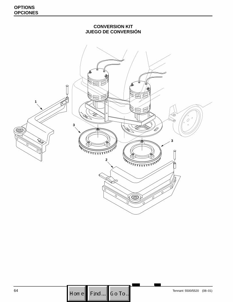
OPTIONSOPCIONES
64 Tennant 5500/5520 (08–01)
CONVERSION KITJUEGO DE CONVERSIÓN
1
3
2
3

OPTIONSOPCIONES
65Tennant 5500/5520 (08–01)
CONVERSION KITJUEGO DE CONVERSIÓN
REF PART # DESCRIPTION QTY.
∇ 609794 �KIT, CONVERSION TO 5500 TEAL 1
609793 �KIT, CONVERSION TO 5520 TEAL 1
� 1 609797 ASM., SKIRT OPERATOR RH TEAL (5500)
1
609795 ASM., SKIRT OPERATOR RH TEAL (5520)
1
� 2 609798 ASM., SKIRT OPERATOR LH TEAL (5500)
1
609796 ASM., SKIRT OPERATOR LH TEAL (5520)
1
∇ � �� ��#(#���%����
� ��������#��#� �� ��#(#��������#��#��#���%����
� �����������# ����#���� #(#�������� #����������� #����####��������#��#�*� ������
REF PART # DESCRIPTION QTY.
� 3 240262 �ASM., PAD DRIVER 2/PK 305MM / 12” (5500)
2
602928 �ASM., PAD DRIVER 2/PK 330MM / 13” (5520)
2
�N/S 603262 ASM., SQUEEGEE CURVED (5500) 1�
603263 ASM, SQUEEGEE CURVED (5520) 1
�N/S 608118 DECAL, “5500” 2�
608119 DECAL, “5520” 2

Rev. 01 (05–01) �2001 Tennant Company Printed in U.S.A
5500/5520
MAINTENANCE CHECK LIST WALL CHARTTo maintain excellent service of this machine, perform this simple check list as described below. Refer to your Operator’s Manual for further assistance.
DESCRIPTION PROCEDUREDAILY� BATTERIES Recharge if needed.
EVERY 4 HOURS
OPERATION � PADS/BRUSHES Remove and clean. Replace if worn.OPERATION
� SQUEEGEE Wipe off with a dry cloth. Store in “up” position.Inspect for damage.
� REC/SOL TANKS Drain and rinse thoroughly. Clean vacuum intake hole.
� ����������������� Remove and rinse thoroughly. Inspect for damage.
� MACHINE Clean with nonabrasive cleaner.
WEEKLY � TANKS/SOLUTION LINE
Flush with .7L (24 oz.) acetic acid solution to 11.4L(3 gal) of water. Rinse afterwards.
EVERY 20 HOURSOPERATION � BATTERIES Check water level, clean battery tops and inspect for
loose or corroded battery cables.
� MACHINE Inspect for loose nuts, bolts and water leaks.MONTHLY� PIVOT POINTS Lubricate with an water resistant oil.EVERY 80 HOURS
OPERATION � FRONT CASTERS Lubricate each caster grease fitting with a waterresistant grease.
EVERY 250 HOURSOPERATION
� VACUUM, DRIVE AND BRUSH MOTORS
Inspect carbon brushes, replace if worn to 10 mm (0.38 in) orless.
TROUBLE SHOOTING GUIDEPROBLEM CAUSE SOLUTION
No power, nothing runs. Faulty main switch Contact Service Center.No power, nothing runs.Batteries need charging. See CHARGING BATTERIES.Faulty battery(s). Replace battery(s).Loose battery cable. Tighten loose cable.MAIN circuit breaker has tripped. Determine cause and reset breaker
button.Brush motors do not run. Brush/Solution switch is not on. Turn on brush/solution switch.Brush motors do not run.
Control grips are not rotated. Rotate control grips.Brush circuit breaker(s) has tripped. Clean or replace pad or brush and
reset brush circuit breaker button.Faulty brush motor or wiring. Contact Service Center.
Carbon brushes worn. Contact Service Center.Faulty brush switch or solenoid. Contact Service Center.
TROUBLE SHOOTING GUIDE continued on back side.

TROUBLE SHOOTING GUIDE - ContinuedPROBLEM CAUSE SOLUTION
Vacuum motor does not run. Faulty vacuum switch. Contact Service Center.Vacuum motor does not run.Vacuum circuit breaker has tripped. Remove obstruction and reset breaker.Faulty vacuum motor or wiring. Contact Service Center.Carbon brushes worn. Contact Service Center.
Drive motor does not run. Drive motor circuit breaker has tripped. Determine cause and reset breaker.Drive motor does not run.Faulty speed control circuit board orconnection.
Contact Service Center.
Faulty solenoid. Contact Service Center.Faulty drive motor. Contact Service Center.
Faulty wiring. Contact Service Center.
Worn carbon brushes. Contact Service Center.
Drive motor runs, but not correctly.
Faulty potentiometer or speed controlboard.
Contact Service Centercorrectly.
Loose wire connection. Contact Service Center.
Little or no solution flow. Solution line or solution tank filter isclogged.
Remove hose and blow compressedair through it. Flush solution tank aftereach use.
Solution valve or solenoid is clogged. Remove valve or solenoid and clean.Do not scratch inside of valve.
Faulty solution switch or solenoid. Contact Service Center.
Solution flow adjustment knob needsadjusting.
Turn solution flow knob clockwise toincrease flow.
Short run time. Batteries not fully charged. Charge batteries.Short run time.Bad cell in one or more batteries. Replace batteries.Batteries need maintenance. See BATTERY MAINTENANCE.Faulty charger. Replace battery charger.
Poor water pick up. Recovery tank is full. Empty recovery tank.Poor water pick up.Float shutoff screen inside recoverytank is clogged.
Remove screen and clean.
Squeegee is clogged with debris. Clean squeegee.Squeegee blades are worn. Replace squeegee blades.Squeegee thumbscrews are loose. Tighten thumbscrews.Vacuum hose connections are looseor hose has a hole.
Push hose cuffs firmly on connections.Replace hose if damaged..
Recovery tank inlet hole is obstructed. Empty recovery tank and tilt tank side-ways to access inlet hole, remove obstruction.
Tank gasket is defective. Replace gasket.Drain hose plug is loose. Tighten drain plug.Recovery tank lid is loose. Tighten lid.Vacuum motor is loose. Contact Service Center.Battery charge level is low. Charge batteries. Do not run machine
when battery meter is in the red zone.
Safety lights do not work. Flasher is burned out. Contact Service Center.
FOR SAFETY: Before attempting any maintenance procedures on machine, stop on level surface,turn off and disconnect battery charger. Repairs must be performed by authorized personnel.