Embed Size (px)
Citation preview

Nortel Ethernet Routing Switch 5500 Series
Installation
NN47200-300.

Document status: StandardDocument version: 03.02Document date: 16 December 2008
Copyright © 2005 - 2008 , Nortel NetworksAll Rights Reserved.
The information in this document is subject to change without notice. The statements, configurations, technicaldata, and recommendations in this document are believed to be accurate and reliable, but are presented withoutexpress or implied warranty. Users must take full responsibility for their applications of any products specified in thisdocument. The information in this document is proprietary to Nortel Networks Inc.
The software described in this document is furnished under a license agreement and may be used only in accordancewith the terms of that license.
Restricted rights legendUse, duplication, or disclosure by the United States Government is subject to restrictions as set forth in subparagraph(c)(1)(ii) of the Rights in Technical Data and Computer Software clause at DFARS 252.227-7013.
Notwithstanding any other license agreement that may pertain to, or accompany the delivery of, this computersoftware, the rights of the United States Government regarding its use, reproduction, and disclosure are as set forthin the Commercial Computer Software-Restricted Rights clause at FAR 52.227-19.
Statement of conditionsIn the interest of improving internal design, operational function, and/or reliability, Nortel Networks reserves the rightto make changes to the products described in this document without notice.
Nortel Networks does not assume any liability that may occur due to the use or application of the product(s) orcircuit layout(s) described herein.
International regulatory statements of conformityThis is to certify that the Nortel Networks Ethernet Routing Switch 5500 Series was evaluated to the internationalregulatory standards for electromagnetic compliance (EMC) and safety and were found to have met the requirementsfor the following international standards:
• EMC - Electromagnetic Emissions - CISPR 22, Class A
• EMC - Electromagnetic Immunity - CISPR 24
• Electrical Safety - IEC 60950, with CB member national deviations
Further, the equipment has been certified as compliant with the national standards as detailed below.
National electromagnetic compliance (EMC) statements of complianceFCC statement (USA Only)
This equipment has been tested and found to comply with the limits for a Class A digital device, pursuant to Part15 of the Federal Communications Commission (FCC) rules. These limits are designed to provide reasonableprotection against harmful interference when the equipment is operated in a commercial environment. Thisequipment generates, uses, and can radiate radio frequency energy. If it is not installed and used in accordance withthe instruction manual, it may cause harmful interference to radio communications. Operation of this equipmentin a residential area is likely to cause harmful interference, in which case users will be required to take whatevermeasures may be necessary to correct the interference at their own expense.
ICES statement (Canada only)
Canadian Department of Communications Radio Interference Regulations
This digital apparatus (Nortel Ethernet Routing Switch 5500 Series) does not exceed the Class A limits for radio-noiseemissions from digital apparatus as set out in the Radio Interference Regulations of the Canadian Department ofCommunications.

Règlement sur le brouillage radioélectrique du ministère des Communications
Cet appareil numérique (Nortel Ethernet Routing Switch 5500 Series) respecte les limites de bruits radioélectriquesvisant les appareils numériques de classe A prescrites dans le Règlement sur le brouillage radioélectrique duministère des Communications du Canada.
CE marking statement (Europe only)
EN 55 022 statements
This is to certify that the Nortel Ethernet Routing Switch 5500 Series are shielded against the generation of radiointerference in accordance with the application of Council Directive 89/336/EEC. Conformity is declared by theapplication of EN 55 022 Class A (CISPR 22).
CAUTIONThis device is a Class A product. In a domestic environment, this device can cause radiointerference, in which case the user may be required to take appropriate measures.
EN 55024 statement
This is to certify that the Nortel Ethernet Routing Switch 5500 Series are shielded against the susceptibility toradio interference in accordance with the application of Council Directive 89/336/EEC. Conformity is declared bythe application of EN 55 024 (CISPR 24).
EN 300386 statement
The Ethernet Routing witch 5500 Series complies with the requirements of EN 300386 V1.3.1 for emissions andfor immunity for a Class A device intended for use in either Telecommunications centre or locations other thantelecommunications centres given the performance criteria as specified by the manufacturer.
European Union and European Free Trade Association (EFTA) notice
All products labeled with the CE marking comply with R&TTE Directive (1995/5/EEC) whichincludes the Electromagnetic Compliance (EMC) Directive (89/336/EEC) and the LowVoltage Directive (73/336/EEC) issued by the Commission of the European Community.
Compliance with these directives implies conformity to the following European Norms (ENs). The equivalentinternational standards are listed in parenthesis.
• EN 55022 (CISPR 22)–Electromagnetic Interference
• EN 55024 (IEC 61000-4-2, -3, -4, -5, -6, -8, -11)–Electromagnetic Immunity
• EN 61000-3-2 (IEC 610000-3-2)–Power Line Harmonics
• EN 61000-3-3 (IEC 610000-3-3)–Power Line Flicker
VCCI statement (Japan/Nippon only)
This is a Class A product based on the standard of the Voluntary Control Council for Interference (VCCI) forinformation technology equipment. If this equipment is used in a domestic environment, radio disturbance may arise.When such trouble occurs, the user may be required to take corrective actions.
BSMI statement (Taiwan only)

This is a Class A product based on the standard of the Bureau of Standards, Metrology and Inspection (BSMI)CNS 13438, Class A.
MIC notice (Republic of Korea only)
This device has been approved for use in Business applications only per the Class A requirements of the Republic ofKorea Ministry of Information and Communications (MIC). This device may not be sold for use in a non-businessapplication.
Observe the Regulatory Marking label on the bottom surface of the chassis for specific certification informationpertaining to this model. Each model in the Nortel Ethernet Routing Switch 5500 Series which is approved forshipment to/usage in Korea is labeled as such, with all appropriate text and the appropriate MIC reference number.
National safety statements of complianceEN 60 950 statement
This is to certify that the Nortel Ethernet Routing Switch 5500 Series are in compliance with the requirements ofEN 60 950 in accordance with the Low Voltage Directive. Additional national differences for all European Unioncountries have been evaluated for compliance.
NOM statement (Mexico only)
The following information is provided on the devices described in this document in compliance with the safetyrequirements of the Norma Oficial Méxicana (NOM):
Exporter: Nortel Networks, Inc.4655 Great America ParkwaySanta Clara CA 95054 USA
Importer: Nortel Networks de México, S.A. de C.V.Avenida Insurgentes Sur #1605Piso 30, OficinaCol. San Jose InsurgentesDeleg-Benito JuarezMéxico D.F. 03900
Tel: 52 5 480 2100
Fax: 52 5 480 2199
Input: Nortel Ethernet Routing Switch 5510 / 5530
100 - 240 VAC, 50/60 Hz,1.3 A max
Nortel Ethernet Routing Switch 5520
100 - 240 VAC, 50/60 Hz, 6.5 A max
Información NOM (unicamente para México)
La información siguiente se proporciona en el dispositivo o en los dispositivos descritos en este documento, encumplimiento con los requisitos de la Norma Oficial Méxicana (NOM):

Exportador: Nortel Networks, Inc.4655 Great America ParkwaySanta Clara, CA 95054 USA
Importador: Nortel Networks de México, S.A. de C.V.Avenida Insurgentes Sur #1605Piso 30, OficinaCol. San Jose InsurgentesDeleg-Benito JuarezMéxico D.F. 03900
Tel: 52 5 480 2100
Fax: 52 5 480 2199
Embarcar a: Nortel Ethernet Routing Switch 5510 / 5530
100 - 240 VAC, 50/60 Hz,1.3 A max
Nortel Ethernet Routing Switch 5520
100 - 240 VAC, 50/60 Hz, 6.5 A max
Denan statement (Japan/Nippon only)
National Environmental Statements of ComplianceThe WEEE Directive 2002/96/EC and RoHS (Restriction of Hazardous Substances) Directive 2002/95/EC setscollection, recycling and recovery targets for various categories of electrical products and their waste.
Restriction on Hazardous Substances Directive ComplianceStatementThe Restriction on Hazardous Substances Directive (RoHS) (2002/95/EC), which accompanies the WEEE Directive,bans the use of heavy metals and brominated flame-retardants in the manufacture of electrical and electronicequipment. Specifically, restricted materials under the RoHS Directive are Lead (including solder used in PCB’s),Cadmium, Mercury, Hexavalent Chromium, and Bromine.
Nortel declares compliance with the European Union (EU) RoHS Directive (2002/95/EC).
WEEE Directive Compliance Statement
This product at end of life is subject to separate collection and treatment in theEU Member States, Norway, and Switzerland and therefore is marked with thesymbol shown at the left. Treatment applied at end of life of these products inthese countries shall comply with the applicable national laws implementingDirective 2002/96/EC on Waste of Electrical and Electronic Equipment (WEEE).
Nortel declares compliance with the European Union (EU) WEEE Directive(2002/96/EC).


7
Revision History
Date Revised Version Reason for revision
May 2005 1.00 New document for Software Release 4.2
July 2006 2.00 Updated document for Software Release 5.0
August 2007 3.01 Updated document for Software Release 5.1
December 2008 3.02 Updated document for Software Release 5.1
Nortel Ethernet Routing Switch 5500 SeriesInstallation
NN47200-300 03.02 Standard5.1 16 December 2008
Copyright © 2005 - 2008 , Nortel Networks
.

8 Revision History
Nortel Ethernet Routing Switch 5500 SeriesInstallation
NN47200-300 03.02 Standard5.1 16 December 2008
Copyright © 2005 - 2008 , Nortel Networks
.

9
Contents
Preface 11Nortel Ethernet Routing Switch 5500 Series 11Related publications 12Finding the latest updates on the Nortel web site 13How to get help 13
Installing the Nortel Ethernet Routing Switch 15Phone Dongle Part Number 16Electrostatic discharge 16
Preventing electrostatic discharge damage 16Preventing electrostatic damage in new cable installations 16
Environmental requirements 17Package contents 19Installing the Nortel Ethernet Routing Switch 5500 Series on a table or shelf 20Installing the Nortel Ethernet Routing Switch 5500 Series in an equipment rack 21Installing a Nortel Ethernet Routing Switch 5530-24TFD in a rear mounted
configuration 23Cabling requirements for the Nortel Ethernet Routing Switch 5500 Series 24Installation and removal of SFP and XFP transceivers 25
Installation of SFP and XFP transceivers 25Removal of SFP and XFP transceivers 26
RJ-45 connector pin assignments 27Nortel Ethernet Routing Switch 5510 and 5530 28Nortel Ethernet Routing Switch 5520-24T-PWR and 5520-48T-PWR 28
Console port pin assignments 29Universal Serial Bus (USB) ports (5530-24TFD only) 29Power specifications for the Nortel Ethernet Routing Switch 5500 Series 30
Nortel Ethernet Routing Switch 5510-24T and 5510-48T 30Nortel Ethernet Routing Switch 5520-24T-PWR and 5520-48T-PWR 30Nortel Ethernet Routing Switch 5530-24TFD 31Nortel Ethernet Power Supply 10 power specification 32Nortel Ethernet Redundant Power Supply 15 power specification 32Nortel Ethernet DC-DC converter module 32
Connecting AC power 32
Nortel Ethernet Routing Switch 5500 SeriesInstallation
NN47200-300 03.02 Standard5.1 16 December 2008
Copyright © 2005 - 2008 , Nortel Networks
.

10 Contents
Power cord specifications 32Connecting power to the back panel 33
Checking LEDs on the Nortel Ethernet Routing Switch 5500 Series 34Front panel LEDs 34Switch LED state indicators 36Port LED state indicators 38Shared SFP transceiver port LED state indicators 39XFP transceiver port LED indicators (5530-24TFD only) 39
Setting IP parameters for the Nortel Ethernet Routing Switch 5500 Series 40Setting IP parameters using the console port and Console Menu 41Setting IP Parameters using the console port and CLI 44Setting IP parameters using the Web-based Management Interface 47Setting IP parameters using the UI button 48
Nortel Ethernet Routing Switch 5500 Series Stack Configuration 49Stack connector 49Stack configuration 51Initial installation 54Stack MAC address 54Temporary base unit 54Removing a stack unit 55Replacing a stack unit 55Stack configurations 56Redundant cascade stacking 59
Translations of safety messages 61
Nortel Ethernet Routing Switch 5500 SeriesInstallation
NN47200-300 03.02 Standard5.1 16 December 2008
Copyright © 2005 - 2008 , Nortel Networks
.

11
Preface
This guide provides information and instructions on the proper installationof a 5500 Series Nortel Ethernet Routing Switch. Please consult anydocumentation included with the switch and the product release notes(see "Related publications" (page 12) for any errata before beginning theinstallation procedure.
To successfully accomplish the installation procedures outlined in thisdocument, the following tools or equipment are required:
• #2 Phillips screwdriver
• An AC power cord that meets the requirements of the appropriate,local electrical codes. See "Connecting AC power" (page 32) for moreinformation on this topic.
• A console cable and connector to match the male DTE connector(DB-9) on the switch.
Nortel Ethernet Routing Switch 5500 Series"5500 Series Switch Platforms" (page 11) outlines the switches that are partof the 5500 Series of Nortel Ethernet Routing Switches
5500 Series Switch Platforms
5500 Series Switch Model Key Features
Nortel Ethernet RoutingSwitch 5510-24T
A 24 port, 10/100/1GBase-T, Layer 4,diffserv-capable, stackable Ethernet switch. Thisswitch contains two Shared SFP TransceiverPorts.
Nortel Ethernet RoutingSwitch 5510-48T
A 48 port, 10/100/1GBase-T, Layer 4,diffserv-capable, stackable Ethernet switch. Thisswitch contains two Shared SFP TransceiverPorts.
Nortel Ethernet RoutingSwitch 5520-24T-PWR
A 24 port, 10/100/1GBase-T, Layer 4,diffserv-capable, stackable Ethernet switchwith full Power over Ethernet (PoE) capability3 (802.3af) on all copper ports. This switchcontains four Shared SFP Transceiver Ports.
Nortel Ethernet Routing Switch 5500 SeriesInstallation
NN47200-300 03.02 Standard5.1 16 December 2008
Copyright © 2005 - 2008 , Nortel Networks
.

12 Preface
5500 Series Switch Model Key Features
Nortel Ethernet RoutingSwitch 5520-48T-PWR
A 48 port, 10/100/1GBase-T, Layer 4,diffserv-capable, stackable Ethernet switchwith full Power over Ethernet (PoE) capability3 (802.3af) on all copper ports. This switchcontains four Shared SFP Transceiver Ports.
Nortel Ethernet RoutingSwitch 5530-24TFD
A 24 port, 10/100/1GBase-T, Layer 4,diffserv-capable, stackable Ethernet switch. Thisswitch contains twelve Shared SFP TransceiverPorts and two XFP Transceiver Ports.
Related publicationsFor more information about the management, configuration, and usage ofthe Nortel Ethernet Routing Switch 5500 Series, refer to the publicationslisted in "Nortel Ethernet Routing Switch 5500 Series Documentation"(page 12)
Nortel Ethernet Routing Switch 5500 Series Documentation
Title Description Part Number
Nortel EthernetRouting Switch 5500Series Release 5.1Installation
Instructions for the installation ofa switch in the Nortel EthernetRouting Switch 5500 Series. It alsoprovides an overview of hardwarekey to the installation, configuration,and maintenance of the switch.
NN47200-300
Nortel EthernetRouting Switch 5500Series Release 5.1Configuration - System
Instructions for the generalconfiguration of switches in the 5500Series that are not covered by theother documentation.
NN47200-500
Nortel EthernetRouting Switch5500 Series Release5.1 Configuration -Security -
Instructions for the configurationand management of security forswitches in the 5500 Series.
NN47200-501
Nortel EthernetRouting Switch5500 Series Release5.1 Configuration -VLANs, SpanningTree, and LinkAggregation
Instructions for the configuration ofspanning and trunking protocols on5500 Series switches
NN47200-502
Nortel Ethernet Routing Switch 5500 SeriesInstallation
NN47200-300 03.02 Standard5.1 16 December 2008
Copyright © 2005 - 2008 , Nortel Networks
.

How to get help 13
Title Description Part Number
Nortel EthernetRouting Switch 5500Series Release 5.1Configuration - IPRouting Protocols
Instructions on the configuration ofIP routing protocols on 5500 Seriesswitches.
NN47200-503
Nortel EthernetRouting Switch 5500Series Release 5.1Configuration - Qualityof Service
Instructions on the configuration andimplementation of QoS and filteringon 5500 Series switches.
NN47200-504
Nortel EthernetRouting Switch 5500Series Release 5.1Configuration - SystemMonitoring
Instructions on the configuration,implementation, and usage ofsystem monitoring on 5500 Seriesswitches.
NN47200-505
Nortel EthernetRouting Switch 5500Series Release Notes- Software Release 5.1
Provides an overview of newfeatures, fixes, and limitations ofthe 5500 Series switches. Alsoincluded are any supplementarydocumentation and document errata
NN47200-400
Installing the NortelEthernet RedundantPower Supply 15
Instructions for the installation andusage of the Nortel Ethernet RPS15.
217070-A
DC-DC ConverterModule for theBaystack 5000 SeriesSwitch
Instructions for the installationand usage of the DC-DC powerconverter.
215081-A
Nortel EthernetRouting Switch 5500Series Installation -SFP
Instructions for the installation andusage of SFP and XFP transceiversand GBICs.
NN47200-302
Finding the latest updates on the Nortel web siteThe content of this documentation was current at the time of release. Tocheck for updates to the documentation and software for the Nortel EthernetRouting Switch 5500 Series, go to the Nortel Web site and use the ProductFinder to select the Nortel Ethernet Routing Switch 5500 Series products.See "How to get help" (page 13) for the link to the Nortel support portal.
How to get helpIf a service contract for the Nortel product has been purchased from adistributor or authorized reseller, contact the technical support staff for thatdistributor or reseller for assistance.
Nortel Ethernet Routing Switch 5500 SeriesInstallation
NN47200-300 03.02 Standard5.1 16 December 2008
Copyright © 2005 - 2008 , Nortel Networks
.

14 Preface
If a Nortel service program was purchased, contact Nortel TechnicalSupport.
The following information is available online:
• contact information for Nortel Technical Support
• information about the Nortel Technical Solutions Centers
• information about the Express Routing Code (ERC) for your product
An ERC is available for many Nortel products and services. When an ERCis used, the call is routed to technical support personnel who specializein supporting the service or product. The ERC for a particular product orservice is available online.
The main Nortel support portal is available at http://www.nortel.com/support.
Nortel Ethernet Routing Switch 5500 SeriesInstallation
NN47200-300 03.02 Standard5.1 16 December 2008
Copyright © 2005 - 2008 , Nortel Networks
.

15
Installing the Nortel Ethernet RoutingSwitch
This section describes the information and procedures used for installingthe Nortel Ethernet Routing Switch 5500 Series. Unless otherwise noted,tasks outlined in this section are applicable to all switches in this series.
This following topics are covered in this section:
• "Phone Dongle Part Number" (page 16)
• "Electrostatic discharge" (page 16)
• "Environmental requirements" (page 17)
• "Package contents" (page 19)
• "Installing the Nortel Ethernet Routing Switch 5500 Series on a tableor shelf" (page 20)
• "Installing the Nortel Ethernet Routing Switch 5500 Series in anequipment rack" (page 21)
• "Cabling requirements for the Nortel Ethernet Routing Switch 5500Series" (page 24)
• " RJ-45 connector pin assignments" (page 27)
• "Console port pin assignments" (page 29)
• " Universal Serial Bus (USB) ports (5530-24TFD only)" (page 29)
• "Power specifications for the Nortel Ethernet Routing Switch 5500Series" (page 30)
• "Connecting AC power" (page 32)
• "Checking LEDs on the Nortel Ethernet Routing Switch 5500 Series"(page 34)
• "Setting IP parameters for the Nortel Ethernet Routing Switch 5500Series" (page 40)
Nortel Ethernet Routing Switch 5500 SeriesInstallation
NN47200-300 03.02 Standard5.1 16 December 2008
Copyright © 2005 - 2008 , Nortel Networks
.
16 Installing the Nortel Ethernet Routing Switch
Phone Dongle Part NumberThe part number for the Nortel Ethernet Routing Switch 5520(5520-24T/48T-PWR) universal phone dongle is DY4311046
Electrostatic dischargeThis section provides information and procedures for the prevention ofelectrostatic discharge during the installation process.
Preventing electrostatic discharge damageElectrostatic discharge (ESD) is a discharge of stored static electricity thatcan damage equipment and impair electrical circuitry. These electrostaticvoltages can result from friction, including, but not exclusive to, pullingcabling through conduits, walking across carpeted areas, and building up ofstatic charge in clothing. ESD damage occurs when electronic componentsare improperly handled and can result in complete or intermittent failures.While networking equipment is commonly designed and tested to withstandcommon mode ESD events, voltage sometimes can be discharged to someconnector pins but not others, or to some pins before others, which has thepotential to damage the networking equipment.
To protect the Nortel Ethernet Routing Switch against ESD damage, takethe following preventive measures before connecting any data cables tothe device:
• Always use anti-static wrist straps. Make sure the strap is adjusted toprovide good skin contact.
• Ensure that work surfaces and equipment racks are properly groundedfor protection against electrostatic discharge. The common point mustbe connected to the building ground wire. In a properly wired building,the nearest reliable ground is typically at the electrical outlet.
• Avoid contact between equipment and clothing. The wrist or anklestrap only protects the equipment from ESD voltages on the body; ESDvoltages on clothing can still cause damage.
• Avoid touching any connector pins.
• Do not remove the wrist or ankle strap until the installation is complete.
Preventing electrostatic damage in new cable installationsWith new cable installations, Nortel recommends that the use of an ESDdischarge cable to reduce the potential for damage from static that can buildup in cables. An example of such a cable is illustrated below.
Nortel Ethernet Routing Switch 5500 SeriesInstallation
NN47200-300 03.02 Standard5.1 16 December 2008
Copyright © 2005 - 2008 , Nortel Networks
.

Environmental requirements 17
ESD cable example
To install the ESD discharge cable:
Step Action
1 Connect the ground lug on the ESD discharge cable to a safe andsuitable earth ground.
2 Briefly connect all RJ-45 cable connectors to the female RJ-45connector of the ESD discharge cable, then connect each RJ-45cable connector to the switch.
3 Leave cables connected to the networking equipment. Once cablesare connected to networking equipment, the cables do not buildup charge.
—End—
Environmental requirements"Nortel Ethernet Routing Switch 5500 Series environmental requirements"(page 17) displays the environmental requirements for the individualswitches in this series. Ensure that the area where the switch is installedand operated will meet these requirements.
Nortel Ethernet Routing Switch 5500 Series environmental requirements
Nortel EthernetRouting Switch5510
Nortel EthernetRouting Switch5520
Nortel EthernetRouting Switch5530
AmbientTemperature
Between 32 and113 degreesFahrenheit (0and 45 degreesCelsius).
Between 32 and104 degreesFahrenheit (0and 40 degreesCelsius) forcontinuousoperation. Thisoperationaltemperature can
Between 32 and122 degreesFahrenheit (0and 50 degreesCelsius) forcontinuousoperation. Thisoperationaltemperature can
Nortel Ethernet Routing Switch 5500 SeriesInstallation
NN47200-300 03.02 Standard5.1 16 December 2008
Copyright © 2005 - 2008 , Nortel Networks
.

18 Installing the Nortel Ethernet Routing Switch
Nortel EthernetRouting Switch5510
Nortel EthernetRouting Switch5520
Nortel EthernetRouting Switch5530
be extended to131 degreesFahrenheit (55degrees Celsius)for short timeoperation.
be extended to 14to 140 degreesFahrenheit (-10to 60 degreesCelsius) for shorttime operation.
Storage Temperature Between -40and 185 degreesFahrenheit (-40and 85 degreesCelsius).
Between -40and 185 degreesFahrenheit (-40and 85 degreesCelsius).
Between -40and 185 degreesFahrenheit (-40and 85 degreesCelsius).
Operating RelativeHumidity
Between 5and 85%non-condensing.
Between 10and 90%non-condensing.
Between 10and 90%non-condensing.
Storage RelativeHumidity
Between 10and 95%non-condensing.
Between 10and 95%non-condensing.
Between 10and 95%non-condensing.
Maximum OperatingAltitude
10,000 feet(3048 meters)above sea level.
10,000 feet(3048 meters)above sea level.
15,000 feet (4572meters) abovesea level.
Storage Altitude Between -1,000and 10,000 feet(-304.8 and 3048meters) abovesea level.
Between -1,000and 10,000 feet(-304.8 and 3048meters) abovesea level.
Between -1,000and 40,000 feet(-340.8 and12,192 meters)above sea level.
Miscellaneous Operating Considerations
• No heat sources such as hot air vents or directsunlight located near the switch.
• No sources of severe electromagnetic interferencelocated near the switch.
• No excessive dust in the environment.
• An adequate power source is located within 6 feet(1.83 meters) of the switch. One 15-amp circuit isrequired for each power supply.
• At least 2 inches (5.08 centimeters) of clearance oneach side of the switch unit for ventilation.
• Adequate clearance is allotted at the front and rearof the switch for access to cables.
Nortel Ethernet Routing Switch 5500 SeriesInstallation
NN47200-300 03.02 Standard5.1 16 December 2008
Copyright © 2005 - 2008 , Nortel Networks
.

Package contents 19
WARNINGTo avoid bodily injury from hazardous electrical shock and current,never remove the top of the device. There are no user-serviceablecomponents inside. For a translation of this statement, see"Translations of safety messages" (page 61).
Package contents"Nortel Ethernet Routing Switch 5500 Series package contents" (page19) illustrates the components that are provided with each switch in the5500 Series. Should any components be missing, contact the vendor fromwhich the switch was purchased.
Nortel Ethernet Routing Switch 5500 Series package contents
1. Nortel Ethernet Routing Switch 5500 Series
2. Rack-mounting hardware that includes:
• Rack-mount brackets
— The Nortel Ethernet Routing Switch 5530-24TFD offers 24 inchrack mounting brackets.
• Screws for attaching brackets to the switch
• Screws for attaching the switch to the equipment rack
• Rubber footpads
3. AC power cord
4. Documentation
Nortel Ethernet Routing Switch 5500 SeriesInstallation
NN47200-300 03.02 Standard5.1 16 December 2008
Copyright © 2005 - 2008 , Nortel Networks
.

20 Installing the Nortel Ethernet Routing Switch
Installing the Nortel Ethernet Routing Switch 5500 Series on a tableor shelf
A single 5500 Series Nortel Ethernet Routing Switch can be installed onany flat surface. The surface should ideally be able to support the combinedweight of the switch and attached cables; between 15 and 20 pounds (7to 9 kilograms).
CAUTIONDo not place a Nortel Ethernet Power Supply Unit 10 or NortelEthernet Redundant Power Supply 15 on top of a Nortel EthernetRouting Switch 5500 Series. The switch housing of a 5500 SeriesNortel Ethernet Routing Switch is not strong enough to supportthe weight of these units. For a translation of this statement, see"Translations of safety messages" (page 61).
To install a 5500 Series switch on a table or shelf, follow this procedure:
Step Action
1 Attach the provided rubber footpads at the locations noted in"Attaching the rubber footpads" (page 20) on the bottom of theswitch.
Attaching the rubber footpads
Nortel Ethernet Routing Switch 5500 SeriesInstallation
NN47200-300 03.02 Standard5.1 16 December 2008
Copyright © 2005 - 2008 , Nortel Networks
.

Installing the Nortel Ethernet Routing Switch 5500 Series in an equipment rack 21
2 Set the switch on a table or shelf as illustrated in "Nortel EthernetRouting Switch on a desk or shelf" (page 21). Allow at least 2 inches(5.1 centimeters) on each side for proper ventilation and at least 5inches (12.7 centimeters) at the back for power cord clearance.
Nortel Ethernet Routing Switch on a desk or shelf
—End—
Installing the Nortel Ethernet Routing Switch 5500 Series in anequipment rack
Before beginning this procedure, ensure that the equipment rack the switchwill be installed in meets these requirements:
• A space of 1.75 inches (4.45 centimeters) is provided for each switch inan EIA or IEC standard 19 inch (48.2 centimeter) equipment rack.
• The rack is bolted to the floor and braced if necessary.
• The rack is grounded to the same grounding electrode used by the powerservice in the area. The ground path must be permanent and must notexceed 1ohm of resistance from the rack to the grounding electrode.
CAUTIONWhen mounting the device in a rack, do not stack units directly ontop of one another in the rack. Each unit must be secured to therack with the appropriate mounting brackets. Mounting bracketsare not designed to support multiple units. For a translation of thisstatement, see "Translations of safety messages" (page 61).
To install a 5500 Series switch in an equipment rack, follow this procedure:
Nortel Ethernet Routing Switch 5500 SeriesInstallation
NN47200-300 03.02 Standard5.1 16 December 2008
Copyright © 2005 - 2008 , Nortel Networks
.

22 Installing the Nortel Ethernet Routing Switch
Step Action
1 Attach a bracket to each side of the switch using a #2 Phillipsscrewdriver as illustrated in "Attaching switch brackets" (page 22).The bracket with the round holes goes on the right side of the switch,where the round fan vents are located.
Attaching switch brackets
2 Slide the switch into the rack as illustrated in "Mounting the switch"(page 22). Insert and tighten the rack-mount screws with a #2Phillips screwdriver.
Mounting the switch
—End—
Nortel Ethernet Routing Switch 5500 SeriesInstallation
NN47200-300 03.02 Standard5.1 16 December 2008
Copyright © 2005 - 2008 , Nortel Networks
.

Installing a Nortel Ethernet Routing Switch 5530-24TFD in a rear mounted configuration 23
Installing a Nortel Ethernet Routing Switch 5530-24TFD in a rearmounted configuration
The Nortel Ethernet Routing Switch 5530-24TFD now features the option ofinstalling the switch in a rear mounted configuration. This option allows theswitch to be installed with the back panel facing forward.
To install the 5530-24TFD in a rear mounted configuration perform thefollowing tasks:
Step Action
1 Attach a bracket to each side of the switch using a #2 Phillipsscrewdriver as illustrated in "Attaching rear mounted switch brackets"(page 23). The bracket with the round holes goes on the right side ofthe switch, where the round fan vents are located.
Attaching rear mounted switch brackets
2 Slide the switch into the rack as illustrated in "Rear mounted switchconfiguration" (page 24). Insert and tighten the rack-mount screwswith a #2 Phillips screwdriver.
Nortel Ethernet Routing Switch 5500 SeriesInstallation
NN47200-300 03.02 Standard5.1 16 December 2008
Copyright © 2005 - 2008 , Nortel Networks
.

24 Installing the Nortel Ethernet Routing Switch
Rear mounted switch configuration
—End—
Cabling requirements for the Nortel Ethernet Routing Switch 5500Series
"Switch cabling requirements" (page 24) outlines the required cables for aNortel Ethernet Routing Switch 5500 Series and their specifications.
Switch cabling requirements
Required Cable Description
10/100/1GBase-T Ports The interconnect cabling must conform to the Cat5e,Cat6, or Cat6e specification of the CommercialBuilding Telecommunications Cabling Standard,ANSI/TIA/EIA 568-B fitted with an RJ-45 ModuleJack.
Console Port Serial cable with a DB-9 female connector on bothends. The maximum length for the console portcable is 25 feet (8.3 meters).
Shared SFP TransceiverPorts
Varies with the installed SFP Transceiver. Refer tothe documentation that was shipped with the SFPTransceiver for specifications.
Nortel Ethernet Routing Switch 5500 SeriesInstallation
NN47200-300 03.02 Standard5.1 16 December 2008
Copyright © 2005 - 2008 , Nortel Networks
.

Installation and removal of SFP and XFP transceivers 25
Required Cable Description
XFP Transceiver Ports Varies with the installed XFP Transceiver. Refer tothe documentation that was shipped with the XFPTransceiver for specifications.
USB Ports USB 2.0 compliant cable with a USB Type Aconnector on both ends.
Note: In Autonegotiation mode, the Nortel Ethernet Routing Switch5500 Series automatically provides the proper MDI/MDI-X connectionon the RJ-45 ports; thereby eliminating the need for crossover cables.When Autonegotiation is disabled on 10/100 ports, they are configuredas an MDI-X connection.
Installation and removal of SFP and XFP transceiversThe following section outlines the installation and removal of SFP andXFP transceivers in the Nortel Ethernet Routing Switch 5500 Series. Forcomplete coverage of SFP and XFP transceiver usage and designation,refer to Installation - SFPs (part number NN47200-302).
Installation of SFP and XFP transceiversThis section details the installation of SFP and XFP transceivers. To installthese transceivers, use the following procedure:
Step Action
1 Remove the transceiver from the protective packaging.
2 Verify that the transceiver is the correct model for the networkconfiguration.
3 Grasp the transceiver between the thumb and forefinger.
4 Insert the transceiver into the proper module on the switch. Apply alight pressure to the transceiver until it clicks and locks into positionin the module.
Nortel Ethernet Routing Switch 5500 SeriesInstallation
NN47200-300 03.02 Standard5.1 16 December 2008
Copyright © 2005 - 2008 , Nortel Networks
.

26 Installing the Nortel Ethernet Routing Switch
Transceiver insertion
5 Remove the dust cover from the transceiver optical bores.
—End—
Removal of SFP and XFP transceiversThis section details the removal of SFP and XFP transceivers. To removethese transceivers, use the following procedure:
Step Action
1 Disconnect the network fiber cable from the transceiver.
2 Use the locking/extractor mechanism on the transceiver to release it.The locking/extractor mechanism varies from model to model.
Nortel Ethernet Routing Switch 5500 SeriesInstallation
NN47200-300 03.02 Standard5.1 16 December 2008
Copyright © 2005 - 2008 , Nortel Networks
.

RJ-45 connector pin assignments 27
Transceiver locking/extractor mechanism examples
3 Slide the transceiver out of the module slot.
4 If the transceiver does not slide easily from the module slot, use agentle side-to-side rocking motion while firmly pulling the transceiverfrom the slot.
5 Attach a dust cover over the fiber optic bores and store thetransceiver in a safe place until needed.
Note: Transceivers should be discarded in accordance with theproper laws and regulations.
—End—
RJ-45 connector pin assignmentsThe following section outlines the connector pin assignments for the RJ-45connectors in the Nortel Ethernet Routing Switch 5500 Series switches.
Consult the appropriate section for specific information on an individualswitch:
• "Nortel Ethernet Routing Switch 5510 and 5530" (page 28)
• "Nortel Ethernet Routing Switch 5520-24T-PWR and 5520-48T-PWR"(page 28)
Nortel Ethernet Routing Switch 5500 SeriesInstallation
NN47200-300 03.02 Standard5.1 16 December 2008
Copyright © 2005 - 2008 , Nortel Networks
.

28 Installing the Nortel Ethernet Routing Switch
Nortel Ethernet Routing Switch 5510 and 5530The following table outlines the RJ-45 connector pin assignments in theNortel Ethernet Routing Switch 5510 and 5530 switches.
5510 RJ-45 connector pin assignments
Connector Pin Number Signal for 10/100Base-TMDI configuration
Signal for 10/100Base-T MDI-X configuration
1 Output transmit data +(TX+)
Input receive data +(RX+)
2 Output transmit data -(TX-)
Input receive data -(RX-)
3 Input receive data +(RX+)
Output transmit data +(TX+)
6 Input receive data - (RX-) Output transmit data -(TX-)
4, 5, 7, 8 Not used Not used
Pin Number Signal for 1GBase-TMDI configuration
Signal for 1GBase-TMDI-X configuration
1 TP0+ TP1+
2 TP0- TP1-
3 TP1+ TP0+
4 TP2+ TP3+
5 TP2- TP3-
6 TP1- TP0-
7 TP3+ TP2+
8 TP3- TP2-
Nortel Ethernet Routing Switch 5520-24T-PWR and 5520-48T-PWRThe following table outlines the RJ-45 connector pin assignments in theNortel Ethernet Routing Switch 5520.
5520 RJ-45 connector pin assignments
Connector Pin Number Signal Description
1 RX+/power+ Receive Data+/power+
2 RX-/power+ Receive Data-/power+
3 TX+/power- Transmit Data+/power-
4 Not applicable Not applicable
5 Not applicable Not applicable
6 TX-/power- Transmit Data-/power-
Nortel Ethernet Routing Switch 5500 SeriesInstallation
NN47200-300 03.02 Standard5.1 16 December 2008
Copyright © 2005 - 2008 , Nortel Networks
.

Universal Serial Bus (USB) ports (5530-24TFD only) 29
Connector Pin Number Signal Description
7 Not applicable Not applicable
8 Not applicable Not applicable
Note: The Nortel Ethernet Routing Switch 5520 uses pins 1, 2, 3, and 6for the purposes of Power over Ethernet (PoE).
Console port pin assignments" Console port pin assignments" (page 29) outlines the console port pinassignments in the Nortel Ethernet Routing Switch 5500 Series.
Console port pin assignments
Connector Pin Number Signal
1 Carrier detect (not used)
2 Transmit Data (TXD)
3 Receive Data (RXD)
4 Data terminal ready (not used)
5 Signal ground (GND)
6 Not used
7 Request to send (not used)
8 Not used
9 Ring indicator (not used)
Universal Serial Bus (USB) ports (5530-24TFD only)The Nortel Ethernet Routing Switch 5530-24TFD features USB ports on thefront panel adjacent to the console port and on the back panel. The additionof USB ports will enable switch administrators to perform tasks that werepreviously completed through TFTP with a commonly available USB MassStorage Device ("flash drive" or "thumb drive"). These tasks include:
• Software Download
• Syslog Backup
• ASCII Configuration File Generation and Download
File and system operations will be limited by the size of the USB device inuse.
Only USB drives that comply with the Mass Storage sub-section of the USB1.1 and USB 2.0 specification are supported. Support is not extended tothird-party devices that do not comply with these standards. Off-the-shelf
Nortel Ethernet Routing Switch 5500 SeriesInstallation
NN47200-300 03.02 Standard5.1 16 December 2008
Copyright © 2005 - 2008 , Nortel Networks
.

30 Installing the Nortel Ethernet Routing Switch
drives that do no comply with these standards may not operate with the5530-24TFD switch. Consult the documentation provided with the USBdrive to ensure compliance with these standards.
Note: The Nortel Ethernet Routing Switch 5530-24TFD also has a backpanel USB port that is currently not enabled.
Power specifications for the Nortel Ethernet Routing Switch 5500Series
The following section describes the power specifications for the switchesin the 5500 Series. Consult the appropriate section below for specificinformation on the appropriate switch:
• "Nortel Ethernet Routing Switch 5510-24T and 5510-48T" (page 30)
• "Nortel Ethernet Routing Switch 5520-24T-PWR and 5520-48T-PWR"(page 30)
• "Nortel Ethernet Routing Switch 5530-24TFD" (page 31)
In addition, the switches in the 5500 Series can make use of redundantpower supplies tailored specifically to their needs. For information on theseunits, see the sections listed below:
• "Nortel Ethernet Power Supply 10 power specification" (page 32)
• " Nortel Ethernet Redundant Power Supply 15 power specification"(page 32)
• " Nortel Ethernet DC-DC converter module" (page 32)
Nortel Ethernet Routing Switch 5510-24T and 5510-48TThe following are the power specifications for the Nortel Ethernet RoutingSwitch 5510.
AC power specifications
Input Current: 1.3 to 0.65A
Input Voltage (rms): 100 to 240 VAC at 47 to 63 Hz
Power Consumption: 135W
Thermal Rating 460 BTU/Hr maximum
Nortel Ethernet Routing Switch 5520-24T-PWR and 5520-48T-PWRTo provide DTE power to all 48 ports at 15.4W per port the Nortel EthernetRouting Switch 5520 needs to use power from the Nortel EthernetRedundant Power Supply 15 (RPS 15).
Nortel Ethernet Routing Switch 5500 SeriesInstallation
NN47200-300 03.02 Standard5.1 16 December 2008
Copyright © 2005 - 2008 , Nortel Networks
.

Power specifications for the Nortel Ethernet Routing Switch 5500 Series 31
AC power specifications
Input Current: 6.5A at 115VAC or 3.25A at 230VAC
Input Voltage (rms): 100 to 240 VAC 50/60 Hz
Power Consumption: 600W maximum
Thermal Rating: 850 BTU/Hr
Inrush Current: 20A 120VAC at maximum load, 40A 240VAC atmaximum load
Turn on Condition: 1 second maximum after application of AC power.
Note: 12V output rise time, from 10% to 90%, shallbe a maximum of 50 ms and monotonic under alldefined input and output conditions.
Efficiency: 70% minimum
Nortel Ethernet Routing Switch 5530-24TFDThe following are the power specifications for the Nortel Ethernet RoutingSwitch 5530.
AC power specifications
Input Current: 1.7A at 120VAC or 0.85A at 240VAC
Input Voltage (rms): 100 to 240VAC 50/60 Hz
Typical Power Consumption: 125W
Typical Thermal Rating: 427 BTU/Hr
Maximum Power Consumption: 150W
Maximum Thermal Rating: 512 BTU/Hr
Inrush Current:20A 120VAC at maximum load, 40A240VAC at maximum load
Turn on Condition:
1 second maximum after application of ACpower.
Note: 12V output rise time, from 10% to90%, shall be a maximum of 50 ms andmonotonic under all defined input andoutput conditions.
Efficiency: 70% minimum
Nortel Ethernet Routing Switch 5500 SeriesInstallation
NN47200-300 03.02 Standard5.1 16 December 2008
Copyright © 2005 - 2008 , Nortel Networks
.

32 Installing the Nortel Ethernet Routing Switch
Nortel Ethernet Power Supply 10 power specification
Output Current: 4.2A maximum
Output Voltage: -48 VDC
Output Power: 200W maximum
Nortel Ethernet Redundant Power Supply 15 power specificationA DC power supply used with the AC power supply to provide DTE power toall of the PoE ports in the Nortel Ethernet Routing Switch 5520.
RPS power specifications
Input Voltage: 100 to 240 VAC 50/60 Hz
Input Current: 10A maximum
Inrush Current: 40A maximum (regardless of ambienttemperature)
Output Voltage: 47.5 VDC
Output Current: 12.0A
Output Power: 600W
Nortel Ethernet DC-DC converter moduleThe Nortel Ethernet Routing Switch 5510 requires an additional DC-DCconverter module to make use of the Nortel Ethernet Routing SwitchRedundant Power Supply Model 15 (RPS 15). This module is requiredto connect the RPS 15 to the Nortel Ethernet Routing Switch 5510 butis not required for other switches in the 5500 Series. For information onconnecting this module to the 5510, see DC-DC Converter Module for theBaystack 5000 Series Switch (Part Number 215081-A).
Connecting AC powerPower cord specifications
To connect AC power to the switch an appropriate AC power cord is requiredas outlined in the "Preface" (page 11). Refer to " International power cordspecifications" (page 33) for plug specifications.
Nortel Ethernet Routing Switch 5500 SeriesInstallation
NN47200-300 03.02 Standard5.1 16 December 2008
Copyright © 2005 - 2008 , Nortel Networks
.

Connecting AC power 33
International power cord specifications
Country / Plug Specification Specifications TypicalPlug
Continental Europe:
• CEE7 standard VII male plug
• Harmonized cord (HAR marking on theoutside of the cord jacket to comply withthe CENELEC Harmonized DocumentHD-21)
• 220 or 230VAC
• 50 Hz
• Single Phase
United States of America / Canada /Japan:
• NEMA5-15P male plug
• UL-recognized (UL stamped on cordjacket)
• CSA-certified (CSA label secured to thecord)
• 100 or 120VAC
• 50 - 60 Hz
• Single Phase
United Kingdom:
• BS1363 male plug with fuse
• Harmonized cord
• 240 VAC
• 50 Hz
• Single Phase
Australia:
• AS3112-1981 male plug
• 240 VAC
• 50 Hz
• Single Phase
DANGERUse only power cords that have a grounding path. Without aproper ground, a person who touches the switch is in danger ofreceiving an electrical shock. Lack of a grounding path to theswitch may result in excessive emissions. For a translation of thisstatement, see "Translations of safety messages" (page 61).
Connecting power to the back panelConnect the AC power cord to the back of the switch and then connect thecord to an AC power outlet. "Connecting AC power to the back panel" (page34) illustrates connecting the AC power cord to the switch back panel.
Note: The Nortel Ethernet Routing Switch 5500 Series do not have anAC power switch. When the power cord is connected to a suitable ACpower outlet, the switch powers up immediately.
Nortel Ethernet Routing Switch 5500 SeriesInstallation
NN47200-300 03.02 Standard5.1 16 December 2008
Copyright © 2005 - 2008 , Nortel Networks
.

34 Installing the Nortel Ethernet Routing Switch
Connecting AC power to the back panel
WARNINGDisconnecting the AC power cord is the only way to turn off ACpower to the Nortel Ethernet Routing Switch 5500 Series. Alwaysconnect the AC power cord in a location that can be reachedquickly and safely in case of an emergency. For a translation ofthis statement, see "Translations of safety messages" (page 61).
Checking LEDs on the Nortel Ethernet Routing Switch 5500 SeriesRefer to the illustrations and tables below for descriptions of the LEDs onthe Nortel Ethernet Routing Switch 5500 Series. The tables describe LEDoperation for a switch that has completed the power-on self-test.
Front panel LEDs"Nortel Ethernet Routing Switch 5510 front panels" (page 34), "NortelEthernet Routing Switch 5520 front panels" (page 35), and "Nortel EthernetRouting Switch 5530-24TFD front panel" (page 35) illustrate the LEDsand buttons found on the front panel of a switch in the 5500 Series NortelEthernet Routing Switch. Refer to the following sections for detailedexplanations of the states indicated by each type of front panel LED:
• "Switch LED state indicators" (page 36)
• "Port LED state indicators" (page 38)
• "Shared SFP transceiver port LED state indicators" (page 39)
• "XFP transceiver port LED indicators (5530-24TFD only)" (page 39)
Note: For more information on the User Interface (UI) button andfront panel configuration mode on the Nortel Ethernet Routing Switch5500 Series, refer to the system configuration guide noted in "Relatedpublications" (page 12).
Nortel Ethernet Routing Switch 5510 front panels
Nortel Ethernet Routing Switch 5500 SeriesInstallation
NN47200-300 03.02 Standard5.1 16 December 2008
Copyright © 2005 - 2008 , Nortel Networks
.

Checking LEDs on the Nortel Ethernet Routing Switch 5500 Series 35
1. User Interface Button 2. Switch LEDs
3. 10/100/1000 Mbps Port LEDs 4. SFP Transceiver Port LEDs
5. Console Port
Nortel Ethernet Routing Switch 5520 front panels
1. User Interface Button 2. Switch LEDs
3. 10/100/1000 Mbps Port LEDs 4. SFP Transceiver Port LEDs
5. Console Port
Nortel Ethernet Routing Switch 5530-24TFD front panel
1. User Interface Button 2. Switch LEDs
3. 10/100/1000 Mbps port LEDs 4. SFP Transceiver Port LEDs
5. Console Port 6. XFP Transceiver Port LEDs
7. USB Port
Nortel Ethernet Routing Switch 5500 SeriesInstallation
NN47200-300 03.02 Standard5.1 16 December 2008
Copyright © 2005 - 2008 , Nortel Networks
.

36 Installing the Nortel Ethernet Routing Switch
Note: Copper ports 13 to 24 and the SFPs are shared ports on theNortel Ethernet Routing Switch 5530-24TFD.
WARNINGFiber optic equipment can emit laser or infrared light that caninjure eyes. Never look into an optical fiber or connector port.Always assume that fiber optic cables are connected to a lightsource. For a translation of this statement, see "Translations ofsafety messages" (page 61).
Switch LED state indicators"Switch LED state indicators" (page 36) outlines the different stateindications that the main switch LEDs display through color and fluctuationcues.
Switch LED state indicators
Label Color / Status Description
White/steady Power is on.UI button
Off Power is off.
Green / steady The switch is connected to AC power and isreceiving power.
Green / blinking Problem with primary Boot image. Booted fromback up image. Configuration and agent codemay be incorrect.
Amber / slowblinking
System will reset in less than 3 seconds. Tostop the reset, release UI push button.
Amber / fastblinking
System will reset in less than 1 second. To stopthe reset, release UI push button.
Pwr
Off The switch is not connected to an AC powersource or the power supply unit is not supplyingpower.
Green / steady • During Initialization: The power-onself-test is complete and the switch isoperating normally.
• After Initialization: The front panelconfiguration mode is inactive. Unit bootedsuccessfully.
Green / blinking • During Initialization: A non-fatal erroroccurred during the self-test.
Status
Nortel Ethernet Routing Switch 5500 SeriesInstallation
NN47200-300 03.02 Standard5.1 16 December 2008
Copyright © 2005 - 2008 , Nortel Networks
.

Checking LEDs on the Nortel Ethernet Routing Switch 5500 Series 37
Label Color / Status Description
• After Initialization: The user pushed theUI button and activated the front panelconfiguration mode and the system isawaiting input.
Amber / steady • During Initialization: N/A
• After Initialization: The front panel hasaccepted the user command. The systemaccepts the UI input and is awaitingexecution.
Amber / blinking • During Initialization: N/A
• After Initialization: The system hasrejected the UI input.
Off The switch failed the self-test.
Green / steady The switch is connected to a redundant powersupply unit (RPSU) and is receiving power ifnecessary.
RPSU
Off The switch is not connected to a RPSU, theRPSU is not supplying power, or the DC/DCmodule is not supplying power.
Green / steady The Cascade Up port has a physical connectionto another unit.
Amber / steady The Cascade Up port has detected an error.
Up
Off The switch is in standalone mode or there is nolink to the Cascade Up port.
Green / steady The Cascade Down port has a physicalconnection to another unit.
Amber / steady The Cascade Down port has detected an error.
Down
Off The switch is in standalone mode or there is nolink to the Cascade Down port.
Green / steady The switch is the stack base unit.
Green / blinking There is a stack configuration error. Eithermultiple base units or no base units areconfigured in the stack.
Amber / steady The switch is operating as the temporary baseunit in the stack configuration.
Base
Off The switch is not the stack base unit or it isoperating in standalone mode.
Nortel Ethernet Routing Switch 5500 SeriesInstallation
NN47200-300 03.02 Standard5.1 16 December 2008
Copyright © 2005 - 2008 , Nortel Networks
.

38 Installing the Nortel Ethernet Routing Switch
Port LED state indicatorsThis section outlines the state indicators provided by the port LED throughcolor and fluctuation cues. Refer to the appropriate switch section for furtherinformation:
• "Nortel Ethernet Routing Switch 5510 and 5530" (page 38)
• "Nortel Ethernet Routing Switch 5520-24T-PWR or 5520-48T-PWR"(page 38)
Nortel Ethernet Routing Switch 5510 and 5530
Port LED state indicators for 5510 and 5530 Switches
Label Color / Status Description
Green / steady The port is set to operate at 1000 Mbps.
Amber / steady This port is set to operate at 100 Mbps
Speed
Off When the LNK/ACT LED is green, this portis set to operate at 10 Mbps. When this LEDis off, refer to the LNK/ACT section for moreinformation.
LNK/ACT Green / steady The link is operating normally.
Green / blinking There is activity on the port. The blinking rateindicates the level of activity.
Green / slowblinking
The port has been disabled by the software.
Off The port has no link nor activity.
Nortel Ethernet Routing Switch 5520-24T-PWR or 5520-48T-PWR
Port LED state indicators for 5520 Switches
Label Color / Status Description
Amber / steady 100 Mbps - PoE is off
Amber / pulsing 100 Mbps - PoE is on
Green / AmberAlternating
10 Mbps or No link or Admin disabled or PoE ison. Refer to the speed setting configured forthis port to determine the specific state.
Green / steady 1000 Mbps - PoE is off
Green / pulsing 1000 Mbps - PoE is on
Speed
Off 10 Mbps or No link or Admin disabled or PoE isoff. Refer to the speed setting configured forthis port to determine the specific state.
Nortel Ethernet Routing Switch 5500 SeriesInstallation
NN47200-300 03.02 Standard5.1 16 December 2008
Copyright © 2005 - 2008 , Nortel Networks
.

Checking LEDs on the Nortel Ethernet Routing Switch 5500 Series 39
Label Color / Status Description
Amber / steady PoE DTE short or the power allocated to thisport has been exceeded.
Amber / blinking Power budget exceeded.
Green / steady Link established but no data activity.
Green / blinking There is activity on this port. The blinking rateindicates the level of activity.
LNK/ACT
Off No link.
Shared SFP transceiver port LED state indicatorsThis section outlines the states indicated by the color and fluctuation cuesprovided by the Shared SFP Transceiver Port LEDs.
Shared SFP transceiver Port LED state indicators
Label Color / Status Description
Green / steady The port has a link established.In Use
Off The port does not have a link established.
Green / steady This link is operating normally.
Green / blinking There is activity on the port.
Green / slowblinking
The port has been disabled by the software.
LNK/ACT
Off Indicates that the link has been lost.
Note: The SFP Transceiver ports are shared. When an SFP Transceiveris inserted and the port has a link established, the corresponding frontpanel port is disabled. For more information on shared ports, refer to thesystem configuration guide noted in "Related publications" (page 12).
XFP transceiver port LED indicators (5530-24TFD only)The Nortel Ethernet Routing Switch 5530-24TFD contains two XFPTransceiver Ports with two LEDs labeled Tx (Transmit) and Rx (Receive)."XFP transceiver port LED state indicators" (page 40) outlines the port statesindicated by the color and fluctuation of the XFP Transceiver Port LEDs.
Nortel Ethernet Routing Switch 5500 SeriesInstallation
NN47200-300 03.02 Standard5.1 16 December 2008
Copyright © 2005 - 2008 , Nortel Networks
.

40 Installing the Nortel Ethernet Routing Switch
XFP transceiver port LED state indicators
LED Color / Status Description
Tx Green / steady
Rx Green / steady
Link established.
Tx Green / blinking Transmit activity detected.
Rx Green / blinking Receive activity detected.
Tx Amber / steady Transmit activity enabled.
Rx Amber / steady Fiber connected with signal present.
Tx Amber / blinking XFP has been installed. Laser Transmitter OFF or XFPin Reset.
Rx Amber / blinking XFP has been installed. No Signal Detected or XFPin Reset.
Both Off No XFP installed.
The Amber LEDs are usually only used during the boot process. Under normaloperation, Green is the only color the XFP LED should emit.
Setting IP parameters for the Nortel Ethernet Routing Switch 5500Series
A 5500 Series Nortel Ethernet Routing Switch begins switching operationsafter it has completely booted up and all software modules are initialized. Tomanage the switch using Telnet or SNMP, or to perform TFTP operations,certain IP parameters must be set. In addition, if the switch is beingconnected into a stack configuration, the additional parameters necessaryfor the proper stack operation must be supplied.
For more information on the console menus, and configuring the switch, referto the system configuration guide noted in "Related publications" (page 12).
For the initial set up of a switch, the following IP parameters must beconfigured:
• IP address of the switch or stack
• Subnet mask
• Gateway address
The following procedures are covered for setting initial IP Parameters:
• "Setting IP parameters using the console port and Console Menu" (page41)
• "Setting IP Parameters using the console port and CLI" (page 44)
Nortel Ethernet Routing Switch 5500 SeriesInstallation
NN47200-300 03.02 Standard5.1 16 December 2008
Copyright © 2005 - 2008 , Nortel Networks
.

Setting IP parameters for the Nortel Ethernet Routing Switch 5500 Series 41
• "Setting IP parameters using the Web-based Management Interface"(page 47)
• "Setting IP parameters using the UI button" (page 48)
Setting IP parameters using the console port and Console MenuTo set IP parameters using the console port and Console Menu, perform thefollowing tasks:
Step Action
1 Connect a terminal to the console port of the switch.
Any terminal or PC with an appropriate terminal emulator can beused as the management station. " Terminal emulation settings"(page 41) lists the parameters that must be used with any terminalemulation software used to connect to the switch.
Terminal emulation settings
Property Value
Baud Rate 9600 bps
Data Bits 8
Stop Bits 1
Parity None
Flow Control None
A console cable and connector to match the male DTE connector(DB-9) on the switch is required to connect the terminal to the switchconsole port.
2 Set the terminal protocol on the terminal or terminal emulationprogram to VT100 and VT100/ANSI.
3 Connect to the switch using the terminal or terminal emulationapplication.
4 After the Nortel banner is displayed, press CTRL + Y to display themain menu. The version of the main menu displayed is dependenton whether the switch is part of a standalone or stacked switchconfiguration. "Standalone switch main menu" (page 42) illustratesthe main menu for a standalone configuration and "Stacked switchmain menu" (page 42) illustrates the main menu for a stacked switchconfiguration.
Nortel Ethernet Routing Switch 5500 SeriesInstallation
NN47200-300 03.02 Standard5.1 16 December 2008
Copyright © 2005 - 2008 , Nortel Networks
.

42 Installing the Nortel Ethernet Routing Switch
Standalone switch main menu
IP Configuration/Setup...SNMP Configuration...System Characteristics...Switch Configuration...Console/Comm Port Configuration...Display Hardware Units...Spanning Tree Configuration...TELNET/SNMP/Web Access Configuration...Software Download...Configuration File...Display System Log...Reset...Reset to Default Settings...Shutdown Command...Command Line Interface...Logout...
Use arrow keys to highlight option, press <Return> or<Enter> to select option.
Stacked switch main menu
IP Configuration/Setup...SNMP Configuration...System Characteristics...Switch Configuration...Console/Comm Port Configuration...Identify Unit Numbers...Renumber Stack Units...Display Hardware Units...Spanning Tree Configuration...TELNET/SNMP/Web Access Configuration...Software Download...Configuration File...Display System Log...Reset...Reset to Default Settings...Shutdown Command...Command Line Interface...Logout...
Use arrow keys to highlight option, press <Return> or<Enter> to select option.
5 Select IP Configuration/Setup . . .from the main menu.
Note: The default management VLAN in the Nortel EthernetRouting Switch 5500 Series is VLAN 1. To manage theswitch, ensure that the network management station is onthe management VLAN or is connected to the management
Nortel Ethernet Routing Switch 5500 SeriesInstallation
NN47200-300 03.02 Standard5.1 16 December 2008
Copyright © 2005 - 2008 , Nortel Networks
.

Setting IP parameters for the Nortel Ethernet Routing Switch 5500 Series 43
VLAN through routers. For information on the maintenance andconfiguration of VLANs, refer to the system configuration guidenoted in "Related publications" (page 12).
6 Assign an IP address to the switch.
• For a standalone switch, enter a value in the In-Band Switch IPAddress field in dotted-decimal notation.
• For a stack configuration, enter a value in the In-Band Stack IPAddress field in dotted-decimal notation.
IP Configuration/Setup screen
IP Configuration/Setup
BootP Request Mode: [ BootP When Needed ]
Configurable In Use Last BootP
------------------- --------------- ---------------
In-Band Stack IP Address: [ 0.0.0.0 ] 0.0.0.0 0.0.0.0
In-Band Switch IP Address: [ 0.0.0.0 ] 0.0.0.0 0.0.0.0
In-Band Subnet Mask: [ 0.0.0.0 ] 0.0.0.0 0.0.0.0
Default Gateway: [ 0.0.0.0 ] 0.0.0.0 0.0.0.0
IP Address to Ping: [ 0.0.0.0 ]
Start Ping: [ No ]
Enter text, press <Return> or <Enter> when complete.
Press Ctrl-R to return to previous menu. Press Ctrl-Cto return to Main Menu.
Note: The In-Band Switch IP Address field allows a switch tooperate as a standalone switch. This field is not required forthe operation of a stacked switch. The same value cannot beentered in both the In-Band Switch IP Address field and theIn-Band Stack IP Address field.
7 In the In-Band Subnet Mask field enter the appropriate subnetmask in dotted-decimal notation.
Note: If the In-Band Subnet Mask field does not alreadycontain a value when specifying an IP address for the switch, theswitch software provides an in-use, default value for the subnetmask field. This value is based on the class of the IP addressentered in the previous step.
8 In the Default Gateway field, enter the appropriate default gateway indotted-decimal notation.
Nortel Ethernet Routing Switch 5500 SeriesInstallation
NN47200-300 03.02 Standard5.1 16 December 2008
Copyright © 2005 - 2008 , Nortel Networks
.

44 Installing the Nortel Ethernet Routing Switch
Note: If Nortel Ethernet Routing Switch 5500 Series switchesare being stacked, ensure that one switch is set as the Base Unit.For more information on this topic, refer to system configurationguide noted in "Related publications" (page 12).
9 Press CTRL + C to return to the main menu.
10 Initial IP configuration is now complete. To continue withconfiguration operations, select the appropriate menu item. Todisconnect from the switch select Logout from the main menu.
—End—
Setting IP Parameters using the console port and CLITo set IP parameters using the console port and Command Line Interface,perform the following tasks:
Step Action
1 Connect a terminal to the console port of the switch.
Any terminal or PC with an appropriate terminal emulator can beused as the management station. " Terminal emulation settings"(page 41) lists the parameters that must be used with any terminalemulation software used to connect to the switch.
Terminal emulation settings
Property Value
Baud Rate 9600 bps
Data Bits 8
Stop Bits 1
Parity None
Flow Control None
A console cable and connector to match the male DTE connector(DB-9) on the switch is required to connect the terminal to the switchconsole port.
2 Set the terminal protocol on the terminal or terminal emulationprogram to VT100 and VT100/ANSI.
3 Connect to the switch using the terminal or terminal emulationapplication.
Nortel Ethernet Routing Switch 5500 SeriesInstallation
NN47200-300 03.02 Standard5.1 16 December 2008
Copyright © 2005 - 2008 , Nortel Networks
.

Setting IP parameters for the Nortel Ethernet Routing Switch 5500 Series 45
4 After the Nortel banner is displayed, press CTRL + Y to display themain menu. The version of the main menu displayed is dependenton whether the switch is part of a standalone or stacked switchconfiguration. "Standalone switch main menu" (page 42) illustratesthe main menu for a standalone configuration and "Stacked switchmain menu" (page 42) illustrates the main menu for a stacked switchconfiguration.
Standalone switch main menu
IP Configuration/Setup...SNMP Configuration...System Characteristics...Switch Configuration...Console/Comm Port Configuration...Display Hardware Units...Spanning Tree Configuration...TELNET/SNMP/Web Access Configuration...Software Download...Configuration File...Display System Log...Reset...Reset to Default Settings...Shutdown Command...Command Line Interface...Logout...
Use arrow keys to highlight option, press <Return> or<Enter> to select option.
Stacked switch main menu
IP Configuration/Setup...SNMP Configuration...System Characteristics...Switch Configuration...Console/Comm Port Configuration...Identify Unit Numbers...Renumber Stack Units...Display Hardware Units...Spanning Tree Configuration...TELNET/SNMP/Web Access Configuration...Software Download...Configuration File...Display System Log...Reset...Reset to Default Settings...Shutdown Command...Command Line Interface...
Nortel Ethernet Routing Switch 5500 SeriesInstallation
NN47200-300 03.02 Standard5.1 16 December 2008
Copyright © 2005 - 2008 , Nortel Networks
.

46 Installing the Nortel Ethernet Routing Switch
Logout...
Use arrow keys to highlight option, press <Return> or<Enter> to select option.
5 Select Command Line Interface. . .from the main menu.
Note: The default management VLAN in the Nortel EthernetRouting Switch 5500 Series is VLAN 1. To manage theswitch, ensure that the network management station is onthe management VLAN or is connected to the managementVLAN through routers. For information on the maintenance andconfiguration of VLANs, refer to the system configuration guidenoted in "Related publications" (page 12).
6 Enter the Global Configuration command mode using the enableand configure terminal commands. This is illustrated below.
Entering Global Configuration mode
5530-24TFD#enable5530-24TFD#configure terminalEnter configuration commands, one per line.End with CNTL/Z.5530-24TFD(config)#
7 In the Global Configuration command mode use the ip addresscommand to set the switch or stack IP address. The syntax of thiscommand is outlined below.ip address [stack | switch] <ip_address> [netmask<subnet_mask>] [default-gateway <gateway_address>]The parameters of this command are outlined in the following table.
ip address parameters
Parameter Description
[stack | switch] Use either the stack or switch key word to set theappropriate IP address.
<ip_address> The IP address to be used.
<subnet_mask> The subnet mask to be used.
<gateway_address>
The default gateway address to be used.
8 Initial IP configuration is now complete. To continue withconfiguration operations, use the appropriate CLI commands. Todisconnect from the switch use the logout command to return tothe Console Menu and select Logout from the main menu.
Nortel Ethernet Routing Switch 5500 SeriesInstallation
NN47200-300 03.02 Standard5.1 16 December 2008
Copyright © 2005 - 2008 , Nortel Networks
.

Setting IP parameters for the Nortel Ethernet Routing Switch 5500 Series 47
—End—
Setting IP parameters using the Web-based Management Interface
Note: IP parameters are changed during this procedure. Changes toIP parameters can result in the loss of web browser connectivity to theswitch.
To set IP parameters using the Web-based Management Interface, performthe following tasks:
Step Action
1 Using the procedure "Setting IP parameters using the UI button"(page 48), assign a default IP address to the switch.
2 Connect a computer to the switch through a data port using astandard RJ-45 network cable.
3 Open a web browser on the attached computer and enter the factorydefault IP address of the switch in the following format: http://<IPAddress>.
4 The main screen of the Web-based Management Interface will open.Select Configuration > IP from the menu. This screen is illustratedbelow.
IP configuration screen
5 Using the fields provided, configure the IP parameters. All fieldsare divided into three columns: Configurable, In Use, and LastBootP. The Configurable column is used to configure a new valuefor the field. The In Use column represents the current value usedby the switch and the Last BootP column is used to display a value
Nortel Ethernet Routing Switch 5500 SeriesInstallation
NN47200-300 03.02 Standard5.1 16 December 2008
Copyright © 2005 - 2008 , Nortel Networks
.

48 Installing the Nortel Ethernet Routing Switch
assigned to the field by a BootP request. These fields are outlinedthe following table.
IP Configuration fields
Field Description
In-Band Stack IPAddress
The IP address used by the switch when it is partof a stack.
In-Band Switch IPAddress
The IP address used by the switch when it is astandalone unit.
In-Band SubnetMask
The subnet mask used by the switch.
Default Gateway The default gateway used by the switch.
6 Click Apply.
—End—
Setting IP parameters using the UI buttonIP parameters can also be set by using the front panel User Interface (UI)button. This allows for switch configuration without the need for a Consoleconnection.
Depending on the state of the switch, applying IP parameters in this mannerwill result in either the parameters being applied to the switch itself or toa switch stack. When the unit is in a stack, the UI button on any unit ofthe stack can be used to set the IP parameters. Ensure however thatperforming this procedure does not result in duplicate IP addresses on thenetwork. If the default IP configuration is set, any change to the configuredIP address or subnet mask through the other user interfaces will cause theIn-Use IP configuration of the switch or stack to change. Therefore, thenewly configured IP address must be used to manage the switch or stack.If the unit is being reset using the UI button, wait for 60 seconds after thelast configuration change. The system takes up to 60 seconds to save theconfiguration changes to NVRAM.
The stack can be reset immediately after changing the configuration byusing the UI button without losing any of the changed configuration.
Note 1: The UI button may be used at any time to change the In-UseIP address and subnet mask of the switch. It overrides the currentIn-Use IP address and subnet mask, if any, regardless of the BootPmode settings for the switch or stack.
Note 2: If there is a change in the switch state, that is, if it joins orleaves a stack after the default IP configuration is set, the In-Use IPconfiguration will change, and must be set again using the UI button.
Nortel Ethernet Routing Switch 5500 SeriesInstallation
NN47200-300 03.02 Standard5.1 16 December 2008
Copyright © 2005 - 2008 , Nortel Networks
.

Nortel Ethernet Routing Switch 5500 Series Stack Configuration 49
It should be noted that configuring IP parameters in this manner doesnot have the same amount of control as configuration using a Consoleconnection. Using this procedure will set the IP address to a pre-configureddefault of 192.168.192.168.
To set IP parameters using the UI button, perform the following tasks:
Step Action
1 Press and hold the UI button for 3 seconds.
The unit will now be in configuration mode. The Status LED will nowchange to a blinking green status.
2 Press the UI button 5 times.
The Base LED and the Up and Down LEDs will now be steadyamber to indicate that the button press was recognized.
3 Press the UI button and hold in for 3 seconds to confirm thecommand.
The In-Use IP address will now be changed to 192.168.192.168.The color and status of the Status LED will turn to steady green oncethe command has been accepted. If the command is rejected, theStatus LED turns amber blinking.
4 Initial IP configuration using the UI button is now complete. Tocontinue with switch configuration access the switch through theCommand Line Interface, Web-based Management Interface, orJava Device Manager.
—End—
Nortel Ethernet Routing Switch 5500 Series Stack ConfigurationThe Nortel Ethernet Routing Switch 5500 Series provides the capability forfail-safe stackability. Up to eight 5500 Series devices can be connected in astack to provide uninterrupted connectivity for up to 384 ports. This stack ismanaged as a single unit.
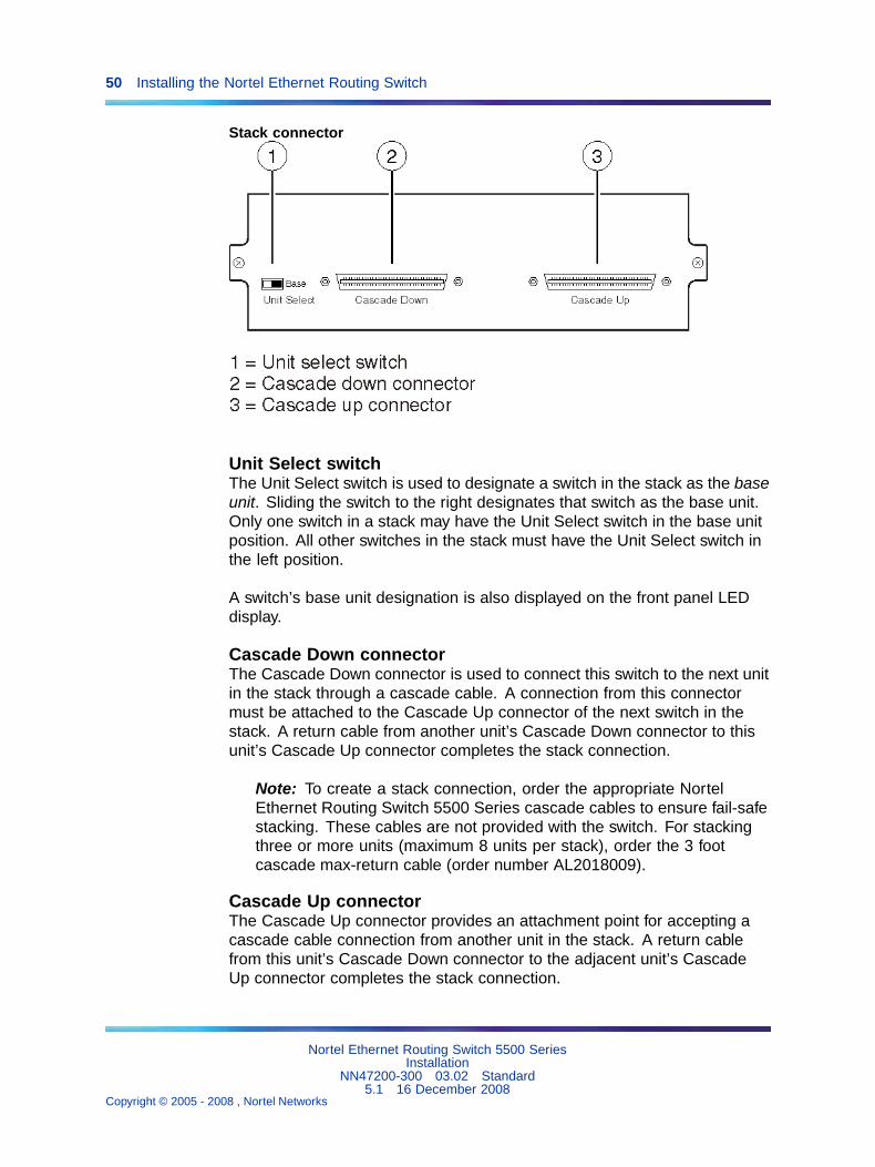
Stack connectorThe stack connector is a component of the Nortel Ethernet Routing Switch5500 Series back panel and consists of the Unit Select switch, CascadeDown connector, and Cascade Up connector. The stack connector isillustrated in the following diagram.
Nortel Ethernet Routing Switch 5500 SeriesInstallation
NN47200-300 03.02 Standard5.1 16 December 2008
Copyright © 2005 - 2008 , Nortel Networks
.
50 Installing the Nortel Ethernet Routing Switch
Stack connector
Unit Select switchThe Unit Select switch is used to designate a switch in the stack as the baseunit. Sliding the switch to the right designates that switch as the base unit.Only one switch in a stack may have the Unit Select switch in the base unitposition. All other switches in the stack must have the Unit Select switch inthe left position.
A switch’s base unit designation is also displayed on the front panel LEDdisplay.
Cascade Down connectorThe Cascade Down connector is used to connect this switch to the next unitin the stack through a cascade cable. A connection from this connectormust be attached to the Cascade Up connector of the next switch in thestack. A return cable from another unit’s Cascade Down connector to thisunit’s Cascade Up connector completes the stack connection.
Note: To create a stack connection, order the appropriate NortelEthernet Routing Switch 5500 Series cascade cables to ensure fail-safestacking. These cables are not provided with the switch. For stackingthree or more units (maximum 8 units per stack), order the 3 footcascade max-return cable (order number AL2018009).
Cascade Up connectorThe Cascade Up connector provides an attachment point for accepting acascade cable connection from another unit in the stack. A return cablefrom this unit’s Cascade Down connector to the adjacent unit’s CascadeUp connector completes the stack connection.
Nortel Ethernet Routing Switch 5500 SeriesInstallation
NN47200-300 03.02 Standard5.1 16 December 2008
Copyright © 2005 - 2008 , Nortel Networks
.

Nortel Ethernet Routing Switch 5500 Series Stack Configuration 51
Note: To create a stack connection, order the appropriate NortelEthernet Routing Switch 5500 Series cascade cables to ensure fail-safestacking. These cables are not provided with the switch.
The following illustration demonstrates the proper crossover connectionconfiguration. Failure to use this configuration can result in loss ofconnectivity.
Connecting cascade cables
1. Base Unit
2. Cascade Cable
3. Cascade Cable (used for return)
Stack configurationSwitches in a stack must be configured to perform as either the base ornon-base units in the stack. The base unit performs important tasks duringstack functioning and it is important that only one switch be designatedas base.
These stack configuration tasks can be performed using either the UserInterface (UI) button on the front panel of the switch or the Unit Select switchon the back. The following sections describe the procedures for performingthese tasks.
Stack configuration using the UI buttonThe UI button can be used to perform a number of stack configuration tasks.This section describes the following tasks:
• "Setting the Base Unit" (page 52)
• "Setting the Non-Base Units" (page 52)
Nortel Ethernet Routing Switch 5500 SeriesInstallation
NN47200-300 03.02 Standard5.1 16 December 2008
Copyright © 2005 - 2008 , Nortel Networks
.

52 Installing the Nortel Ethernet Routing Switch
• "Resetting the stack" (page 53)
• "Abandoning a command" (page 53)
Setting the Base Unit To set the stack base unit with the UI button, followthis procedure:
Step Action
1 Press and hold the UI button for three seconds.
The unit is now in configuration mode. The color and status of theStatus LED turns to blinking green.
2 Press the UI button once.
The Base LED is illuminated and the Up and Down LEDs are steadygreen to indicate that the button press was recognized.
3 Press and hold the UI button for three seconds to confirm thecommand.
The Status LED returns to a steady green state to confirm commandacceptance. If the command is rejected, the Status LED movesto a blinking amber state.
—End—
Note: The switch does not become the base unit until the next time theswitch is restarted.
Setting the Non-Base Units To set the stack non-base units with the UIbutton, follow this procedure:
Step Action
1 Press and hold the UI button for three seconds.
The unit is now in configuration mode. The color and status of theStatus LED turns to blinking green.
2 Press the UI button twice.
The Base LED will turn off and the Up and Down LEDs will moveto a steady green state.
3 Press and hold the UI button for three seconds to confirm thecommands.
Nortel Ethernet Routing Switch 5500 SeriesInstallation
NN47200-300 03.02 Standard5.1 16 December 2008
Copyright © 2005 - 2008 , Nortel Networks
.

Nortel Ethernet Routing Switch 5500 Series Stack Configuration 53
The Status LED returns to a steady green state to confirm commandacceptance. If the command is rejected, the Status LED movesto a blinking amber state.
—End—
Note: The switch does not become the non-base unit until the nexttime the switch is restarted.
Resetting the stack To reset the stack using the UI button, follow thisprocedure:
Step Action
1 Press and hold the UI button for three seconds.
The unit is now in configuration mode. The color and status of theStatus LED turns to blinking green.
2 Press the UI button three times.
The Base, Up, and Down LEDs will move to a blinking amber stateand blink in unison.
3 Press and hold the UI button for three seconds to confirm thecommand.
—End—
Abandoning a command Once a command entered through the UIbutton is accepted, the new configuration is stored in NVRAM. To abort acommand entered using the UI button, perform one of the following actions:
• Wait approximately twenty seconds after entering the command (withoutconfirming it) and the input is ignored.
• Exit configuration mode by pressing the UI button five or more times.
Note: Wait sixty seconds after the last configuration change beforeresetting the unit. The system can take up to this long to saveconfiguration changes to the NVRAM. Stacks can be reset immediatelyafter the last configuration change without any loss of information.
Nortel Ethernet Routing Switch 5500 SeriesInstallation
NN47200-300 03.02 Standard5.1 16 December 2008
Copyright © 2005 - 2008 , Nortel Networks
.

54 Installing the Nortel Ethernet Routing Switch
Stack configuration using the Unit Select switchThe Unit Select switch is used to designate a switch in the stack as a baseor non-base unit. Sliding the switch to the right designates that switch asthe base unit. Only one switch in a stack may have the Unit Select switch inthe base unit position. All other switches in the stack must have the UnitSelect switch in the left position which designates them as non-base units.
Initial installationDuring the initial installation of the stack, the software automaticallydetermines the physical order of all units in the stack according to theposition of the base unit within the stack. Thereafter, the individual unitsmaintain their original unit numbering, even if the position of one or moreunits in the stack is changed.
For example, when the stack is initially powered, the base unit becomes unit1 and the unit that the base unit connects to (via the Cascade Down cable)becomes unit 2 (and the next unit is unit 3 and so on), until the maximumstack configuration (up to 8 units) is reached. If the base unit is changed toanother unit in the stack, the new base unit keeps its original unit numberin the stack.
Stack MAC addressWhen a switch participates in a stack configuration, a stack MAC address isautomatically assigned during stack initialization. The stack MAC address isthe base unit MAC address plus 1. If another unit in the stack is assignedas the base unit, the new stack MAC address is the MAC address of thenew base unit plus 1. The original stack IP address still applies to the newbase unit.
Temporary base unitIf an assigned base unit fails, the next unit in the stack order automaticallybecomes the new temporary base unit. This change is indicated by theBase LED on the temporary base unit LED display panel moving to a steadyamber state.
This automatic failover is a temporary safeguard only. If the stackconfiguration loses power, the temporary base unit will not power up asthe base unit when power is restored. Also, if the original unit rejoins thestack, it will not resume base unit status. For this reason, always assignthe temporary base unit as the base unit until the failed unit is repairedor replaced.
Note: If the temporary base unit is not assigned as the new baseunit, and the temporary base unit fails, the next unit in the stack orderbecomes the temporary base unit. This process will continue aftersuccessive failures until only two units are left in the stack.
Nortel Ethernet Routing Switch 5500 SeriesInstallation
NN47200-300 03.02 Standard5.1 16 December 2008
Copyright © 2005 - 2008 , Nortel Networks
.

Nortel Ethernet Routing Switch 5500 Series Stack Configuration 55
Removing a stack unitIf a unit is removed from the stack (therefore operating in standalone mode),the following switch configuration settings revert to those configured beforethe unit became a member of the stack:
• IP address
• Console, Web, Telnet, and SNMP passwords
• SNMP community strings
Replacing a stack unit
Note: Use only the console interface, command line interface, orWeb-based management system to replace or insert units in the stack.
To replace a failed stack unit or insert a new unit into a stack, follow thisprocedure:
Step Action
1 Upload a copy of the stack configuration file to a TFTP server.
Since unit failure is not a predictable situation, it is suggested thatthe stack configuration file is backed up regularly to a TFTP server.
Note: The stack configuration file must be in binary form.
2 Obtain the new switch.
Ensure that the new switch is set to factory default values. Thisnew unit will be configured in standalone mode before inserting itinto the stack.
3 Download the configuration file to the new unit.
Download the stack configuration file produced in step 1. The newunit will extract the relevant configuration information.
4 Set the unit number.
After the configuration file has been downloaded to the new unit,specify the stack unit that this new unit will replace. The switch willreboot with the stack configuration information.
5 Physically insert the new unit.
Turn off the new unit and physically replace the failed unit in thestack. Complete the cabling to attach the new unit to the stack andturn on the new unit.
—End—
Nortel Ethernet Routing Switch 5500 SeriesInstallation
NN47200-300 03.02 Standard5.1 16 December 2008
Copyright © 2005 - 2008 , Nortel Networks
.

56 Installing the Nortel Ethernet Routing Switch
If the base unit is being replaced, remember that the stack will have electeda temporary base unit. The new unit will not automatically assume the baseunit status. Configure the new unit as the base unit using either the UnitSelect switch or UI button and reset the stack to make the new unit thebase unit.
For a more detailed explanation of this procedure, including an explanationof the Auto Unit Replacement (AUR) feature, see Ethernet Routing Switch5500 Series Configuration — System (NN47200-500).
Stack configurationsDue to stack parameters being associated with the base unit, the physicalstack order depends on the base unit position and whether the stack isconfigured cascade up (stack up) or cascade down (stack down). Thisdesignation depends on the stack cabling arrangement.
The system automatically numbers the physical units based on thedesignated base unit (Unit 1). In a cascade down configuration, the baseunit is physically located as the top unit in the stack. The cable connected tothe Cascade Down connector of the base unit terminates in the Cascade Upconnector on the next unit in the stack which is physically located below thebase unit. This next unit is designated Unit 2. The stack is wired downwardthrough the units and the system continues to number in this mannerthroughout the stack. In this configuration, the base unit discovers thestack in a cascade down (stack down) direction. The following illustrationdemonstrates a cascade down (stack down) configuration.
Nortel Ethernet Routing Switch 5500 SeriesInstallation
NN47200-300 03.02 Standard5.1 16 December 2008
Copyright © 2005 - 2008 , Nortel Networks
.

Nortel Ethernet Routing Switch 5500 Series Stack Configuration 57
Cascade Down (Stack Down) configuration
1. Base Unit
2. Last Unit
3. Cascade Cable
4. Cascade Cable
In a cascade up (stack up) configuration, the base unit is physicallylocated as the top unit in the stack. The cable connected to the CascadeDown connector of the base unit terminates in the Cascade Up connectorphysically located at the bottom of the stack. This next unit is designated Unit2. The stack is wired upward through the units and the system continues tonumber in this manner throughout the stack. In this configuration, the baseunit discovers the stack in a cascade up (stack up) direction. The followingillustration demonstrates a cascade up (stack up) configuration.
Nortel Ethernet Routing Switch 5500 SeriesInstallation
NN47200-300 03.02 Standard5.1 16 December 2008
Copyright © 2005 - 2008 , Nortel Networks
.

58 Installing the Nortel Ethernet Routing Switch
Cascade Up (Stack Up) configuration
1. Base Unit
2. Last Unit
3. Cascade Cable
4. Cascade Cable
Note: Since many network management software packages assumea cascade down (stack down) configuration, Nortel recommends theusage of this configuration.
Regardless of stack configuration, the following applies:
• When power is applied to the stack the base unit initializes, typicallywithin sixty seconds, and the entire stack powers up as a single logicalunit.
• A RS-232 communications cable can be attached to the console port ofany switch in the stack to establish a console connection.
Nortel Ethernet Routing Switch 5500 SeriesInstallation
NN47200-300 03.02 Standard5.1 16 December 2008
Copyright © 2005 - 2008 , Nortel Networks
.

Nortel Ethernet Routing Switch 5500 Series Stack Configuration 59
• A software upgrade can be performed on the stack from any switch usingthe console interface, a Telnet session, the Web-based managementinterface, or any SNMP-based management software.
• The stack can be managed using a Telnet session, Web-basedmanagement interface, or any SNMP-based management softwarethrough any stack switch port.
• When stacking two or more switches. use the three foot cascademax-return cable (part number AL2018009) to complete the link fromthe last unit in the stack to the base unit.
Redundant cascade stackingThe Nortel Ethernet Routing Switch 5500 Series allows a stack of up to 8units into a dual-path cascade stack. If any single unit fails or if a cable isaccidently disconnected, other units in the stack remain operational withoutinterruption.
In addition to increasing bandwidth, the software uses the cables to providetwo paths between units. If one path breaks the data travels over theremaining path with half the normal inter-switch bandwidth.
The following diagram shows an example of how a stack configurationreacts to a failed connection in the stack configuration. In the illustratedexample, the following is occurring:
• Unit 3 becomes non-operational due to a unit failure, cabledisconnection, or a loss of power.
• Units 2 and 4, directly upstream and downstream from Unit 3, sensethe loss of link signals from unit 3. The software causes all the data totraverse the remaining path.
• The Cascade Down LED for Unit 2 and the Cascade Up LED for Unit 4turn amber to indicate an error has been detected.
• The remaining stack units continue to be connected.
Nortel Ethernet Routing Switch 5500 SeriesInstallation
NN47200-300 03.02 Standard5.1 16 December 2008
Copyright © 2005 - 2008 , Nortel Networks
.
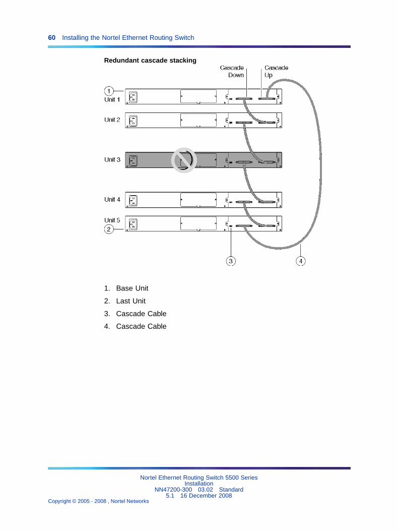
60 Installing the Nortel Ethernet Routing Switch
Redundant cascade stacking
1. Base Unit
2. Last Unit
3. Cascade Cable
4. Cascade Cable
Nortel Ethernet Routing Switch 5500 SeriesInstallation
NN47200-300 03.02 Standard5.1 16 December 2008
Copyright © 2005 - 2008 , Nortel Networks
.

61
Translations of safety messages
CAUTIONWhen mounting this device in a rack, do not stack units directlyon top of one another in the rack. Each unit must be secured tothe rack with appropriate mounting brackets. Mounting bracketsare not designed to support multiple units.
ATTENTIONAchtung:Wenn diese Einheit in einem Rack montiert wird, muß ein gewisser Abstandzur nächsten Einheit gelassen werden. Jede Einheit muß mit geeignetemBefestigungsmaterial gesichert werden. Das Befestigungsmaterial ist nicht für diegleichzeitige Befestigung mehrerer Einheiten geeignet.
ATTENTIONSi vous installez le module dans une baie, ne l’empilez pas directement sur unautre. Chaque module doit être fixé à sa propre baie à l’aide des supports demontage appropriés. Ces supports ne sont pas conçus pour résister à plusieursmodules.
ATTENTIONPrecautión:Cuando monte este dispositivo en un bastidor, no apile las unidades directamenteuna encima de otra. Cada unidad debe fijarse en el bastidor con las abrazaderasde montaje adecuadas. Las abrazaderas de montaje no están diseñadas parasostener varias unidades.
ATTENTIONSe il dispositivo viene installato in un rack, non impilare le unità direttamenteuna sull’altra. Ogni unità deve essere fissata al rack con le staffe di montaggioappropriate. Le staffe di montaggio non sono state progettate per supportarepiù unità.
Nortel Ethernet Routing Switch 5500 SeriesInstallation
NN47200-300 03.02 Standard5.1 16 December 2008
Copyright © 2005 - 2008 , Nortel Networks
.

62 Translations of safety messages
CAUTIONIf you are not installing a module in the slot, be sure to keep themetal cover plate in place over the slot. Removing the cover plateimpedes airflow and proper cooling of the unit.
ATTENTIONAchtung:Wenn Sie kein Modul im Schacht verwenden, muß die Metallabdeckung überdem Schacht montiert sein. Eine Entfernung der Abdeckung führt zu einerVerschlechterung der Luftzirkulation und damit zu einer nicht ausreichendenKühlung der Einheit.
ATTENTIONSi vous n’installez pas le module dans une baie, veillez à laisser la plaquemétallique sur la baie. Si vous la retirez, l’aération du module ne peut pass’effectuer correctement.
ATTENTIONPrecaution:Si no instala ningún módulo en la ranura, asegúrese de mantener la placa de lacubierta de metal en la misma. Si la retira, impedirá que el aire circule y la unidadse refrigere adecuadamente.
Nortel Ethernet Routing Switch 5500 SeriesInstallation
NN47200-300 03.02 Standard5.1 16 December 2008
Copyright © 2005 - 2008 , Nortel Networks
.

Translations of safety messages 63
ATTENTIONAttenzione:Se nello slot non vengono installati moduli, assicurarsi di mantenere la piastra dicopertura metallica in sede sopra lo slot. La rimozione della piastra impedisce laventilazione e il corretto raffreddamento dell’unità.
WARNINGDisconnecting the AC power cord is the only way to turn off ACpower to this device. Always connect the AC power cord in alocation that can be reached quickly and safely in case of anemergency.
Nortel Ethernet Routing Switch 5500 SeriesInstallation
NN47200-300 03.02 Standard5.1 16 December 2008
Copyright © 2005 - 2008 , Nortel Networks
.

64 Translations of safety messages
ATTENTIONWarnung:Das Gerät kann nur durch Ziehen des Netzsteckers ausgeschaltet werden.Schließen Sie das Netzkabel an einer Steckdose an, die in Notfällen schnell undsicher zugänglich ist.
ATTENTIONAvertissement:Pour mettre le module hors tension, vous devez impérativement déconnecter lecordon d’alimentation. En outre, vous devez dégager un espace minimal dans lazone de câblage pour pouvoir y accéder facilement en cas d’urgence.
ATTENTIONAdvertencia:Para apagar el dispositivo debe desenchufar el cable. Conecte siempre el cablede alimentación a una toma segura y de fácil acceso por si se produjera algunasituación de emergencia.
ATTENTIONAvviso:L’unico modo per disattivare questo dispositivo consiste nello scollegare il cavo dialimentazione. Collegare sempre il cavo di alimentazione ad una presa che siafacilmente e rapidamente accessibile in caso di emergenza.
DANGERUse only power cords that have a grounding path. Without aproper ground, a person who touches the switch is in danger ofreceiving an electrical shock. Lack of a grounding path to theswitch may result in excessive emissions.
ATTENTIONVorsicht:Verwenden Sie nur Netzkabel mit Schutzerdung. Ohne ordnungsgemäßeSchutzerdung besteht für Personen, die den Switch berühren, die Gefahr eineselektrischen Schlages. Eine nichtvorhandene Schutzerdung kann zu sehr starkenAbstrahlungen führen.
Nortel Ethernet Routing Switch 5500 SeriesInstallation
NN47200-300 03.02 Standard5.1 16 December 2008
Copyright © 2005 - 2008 , Nortel Networks
.
Translations of safety messages 65
DANGERN’utilisez que des cordons d’alimentation équipés de trajet demise à la terre. Sans mise à la terre adaptée, vous risquez derecevoir une décharge électrique en touchant le commutateur.Par ailleurs, l’absence de trajet de mise à la terre peut générerdes émissions excessives.
ATTENTIONPeligro:Utilice únicamente cables de alimentación con toma de tierra. De lo contrario, altocar el interruptor puede recibir una descarga eléctrica. Si no hay un circuito detoma de tierra en el enchufe, puede producirse un exceso de emisiones.
ATTENTIONPericolo:Utilizzare esclusivamente cavi di alimentazione dotati di un percorso per la messaa terra. Senza un’adeguata messa a terra, chiunque tocchi lo switch corre ilrischio di ricevere una scossa elettrica. L’assenza di un percorso per la messa aterra verso lo switch può comportare un eccesso di emissioni.
Nortel Ethernet Routing Switch 5500 SeriesInstallation
NN47200-300 03.02 Standard5.1 16 December 2008
Copyright © 2005 - 2008 , Nortel Networks
.

66
Index
Symbols/Numerics5530-24TFD USB ports 29
AAccessing technical assistance 13
CCable requirements 24Connecting AC power 32Console pin assignments 29
DDocumentation updates 13
EElectrostatic discharge 16Environmental requirements 17ESD 16
IInitial IP parameters 40Installing the Nortel Ethernet Routing
Switch 15
PPackage contents 19Phone dongle 16Power specifications 30
Preface 11
RRack installation 21Rear mounted installation 23Related publications 12RJ-45 pin assignments 27
SSetting IP parameters 40SFP installation 25SFP removal 26Shelf installation 20Software updates 13Stack configuration 49Switch LEDs 34Switch platforms
TTable installation 20Translations of safety messages 61
UUSB ports 29
XXFP installation 25XFP removal 26
Nortel Ethernet Routing Switch 5500 SeriesInstallation
NN47200-300 03.02 Standard5.1 16 December 2008
Copyright © 2005 - 2008 , Nortel Networks
.


Nortel Ethernet Routing Switch 5500 Series
InstallationCopyright © 2005 - 2008 , Nortel NetworksAll Rights Reserved.
Publication: NN47200-300Document status: StandardDocument version: 03.02Document date: 16 December 2008
To provide feedback, or report a problem in this document, go to http://www.nortel.com/documentfeedback.
Sourced in Canada and the United States of America
The information in this document is subject to change without notice. Nortel Networks reserves the right to make changes in designor components as progress in engineering and manufacturing may warrant.
*Nortel, Nortel Networks, the Nortel logo, and the Globemark are trademarks of Nortel Networks.