Embed Size (px)
Citation preview

1
536634
Fabrik Simulation 24V
Factory Simulation 24V
2
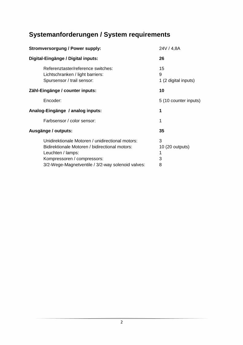
Systemanforderungen / System requirements Stromversorgung / Power supply: 24V / 4,8A
Digital-Eingänge / Digital inputs: 26
Referenztaster/reference switches: 15
Lichtschranken / light barriers: 9
Spursensor / trail sensor: 1 (2 digital inputs)
Zähl-Eingänge / counter inputs: 10
Encoder: 5 (10 counter inputs)
Analog-Eingänge / analog inputs: 1
Farbsensor / color sensor: 1
Ausgänge / outputs: 35
Unidirektionale Motoren / unidirectional motors: 3
Bidirektionale Motoren / bidirectional motors: 10 (20 outputs)
Leuchten / lamps: 1
Kompressoren / compressors: 3
3/2-Wege-Magnetventile / 3/2-way solenoid valves: 8

3
Systemanforderungen SPS System requirements PLC SPS Eingangs- und Ausgangskonfiguration
PLC input and output configuration
Eingänge / inputs Ausgänge / outputs
Typ / type P-lesend / sinking input P-schaltend / sourcing output
Schaltung /
switching
Systemanforderungen für sonstige Steuerungen System requirements for other controllers
Falls statt einer SPS eine andere Steuerung wie z.B. Arduino verwendet wird, so muss
sichergestellt werden, dass die folgenden Anforderungen erfüllt werden.
- Schnittstelle zu Adapterplatine kompatibel zu 24V
- Zykluszeit von min. 10 ms
If instead of a PLC another controller such as Arduino is used, it must be ensured that the
following requirements are met.
- Interface to adaptor-PCB compatible with 24V
- Cycle time at least 10 ms

4
Adapterplatine 24V / adaptor-PCB 24V
Belegung Adapterplatine / Layout adaptor PCB:
Hochregallager Warehouse
Vakuumsauggreifer Vacuum gripper
Bearbeitungsstation Processing station
Sortierstrecke Sorting line
R1/R2 Förderband / Conveyor belt Vertikal / vertical Drehkranz / turntable -
R3/R4 horizontal horizontal - -
R5/R6 vertical Drehkranz / turntable Ofenschieber / oven feeder -
R7/R8 Ausleger / cantilever - Greifer / gripper -
V1 - Vakuum / vacuum Vakuum / vacuum Schieber weiß / pusher white
V2 - - Vakuum / vacuum Schieber rot / pusher red
V3 - - Ofentür /oven door Schieber blau / pusher blue
V4 - - Schieber Drehkranz / pusher turntable -
ST1 (Model) 20 pol. 16 pol. 20 pol. 20 pol.
ST2 (Model) 14 pol. 10 pol. 20 pol. 14 pol.
ST3 (SPS) 34 pol. 34 pol. 34 pol. 34 pol.
Stiftleisten Anschluss Modell / pin headers to connect model
Relais für bidirektionale Motoren / relais for bidirectional motors
17x2 Stiftleiste für Anschluss SPS /
17x2 pin header to connect PLC
Klemmen für Anschluss
SPS (alternativ zu ST3) /
terminals to connect
PLC (alternative to ST3)
Klemmen für Ventile /
Terminals for valves
5
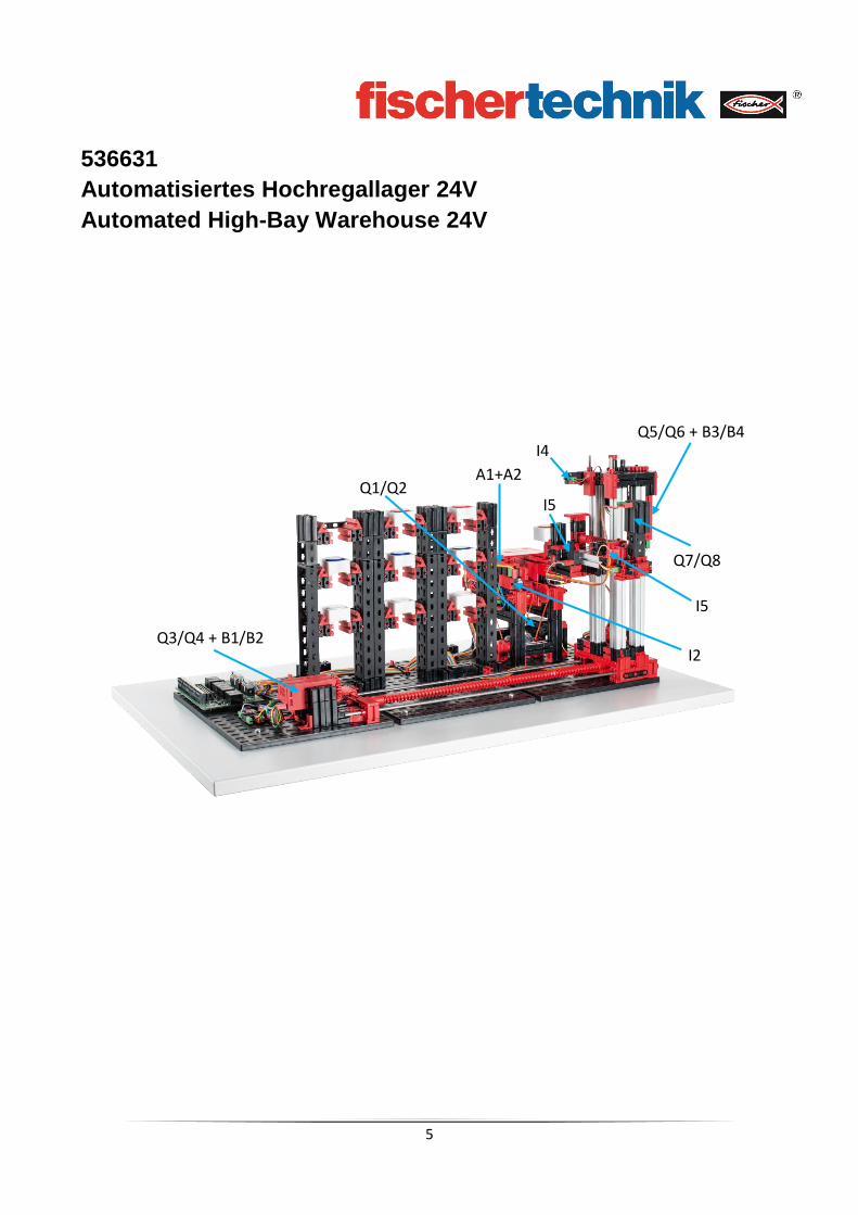
536631
Automatisiertes Hochregallager 24V
Automated High-Bay Warehouse 24V
Q3/Q4 + B1/B2
Q5/Q6 + B3/B4
Q7/Q8
I2
I4
A1+A2
I5
I5
Q1/Q2

6
Systemanforderungen / System requirements Stromversorgung / power supply: 24V / 1,2A
Digital-Eingänge / digital inputs: 8
Referenztaster / reference switches: 4 (I1, I4…I6)
Lichtschranken / light barriers: 2 (I2…I3)
Spursensor / trail sensor: 1 (2 inputs A1…A2)
Zähl-Eingänge: 4
Encoder / encoders: 2 (4 inputs B1…B4)
Ausgänge: 8
Bidirektionale Motoren / bidiectional motors: 4 (8 outputs Q1…Q8)

7
Systemanforderungen SPS System requirements PLC SPS Eingangs- und Ausgangskonfiguration
PLC input and output configuration
Eingänge / inputs Ausgänge / outputs
Typ / type P-lesend / sinking input P-schaltend / sourcing output
Schaltung /
switching
Systemanforderungen für sonstige Steuerungen System requirements for other controllers
Falls statt einer SPS eine andere Steuerung wie z.B. Arduino verwendet wird, so muss
sichergestellt werden, dass die folgenden Anforderungen erfüllt werden.
- Schnittstelle zu Adapterplatine kompatibel zu 24V
- Zykluszeit von min. 10 ms
If instead of a PLC another controller such as Arduino is used, it must be ensured that the
following requirements are met.
- Interface to adaptor-PCB compatible with 24V
- Cycle time at least 10 ms

8
Belegungsplan für Automatisiertes Hochregallager 24V
Circuit layout for Automated High-Bay Warehouse 24V Klemme Nr. Terminal no.
Funktion Function
Eingang/Ausgang Input/Output
1 Stromversorgung (+) Aktoren power supply (+) actuators
24V DC
2 Stromversorgung (+) Sensoren power supply (+) sensors
24V DC
3 Stromversorgung (-) power supply (-)
0V
4 Stromversorgung (-) power supply (-)
0V
5 Referenztaster horizontal reference switch horizontal axis
I1
6 Lichtschranke innen light-barrier inside
I2
7 Lichtschranke außen light-barrier outside
I3
8 Referenztaster vertikal reference switch vertical axis
I4
9 Spursensor (Signal 1, unten) trail sensor (signal 1, lower)
A1
10 Spursensor (Signal 2, oben) trail sensor (signal 2, upper)
A2
11 Encoder horizontal Impuls 1 encoder horizontal axis impulse 1
B1
12 Encoder horizontal Impuls 2 encoder horizontal axis impulse 2
B2
13 Encoder vertikal Impuls 1 encoder vertical axis impulse 1
B3
14 Encoder vertikal Impuls 2 encoder vertical axis impulse 2
B4
15 Referenztaster Ausleger vorne reference switch cantilever front
I5
16 Referenztaster Ausleger hinten reference switch cantilever back
I6
17 Motor Förderband vorwärts motor conveyor belt forward
Q1 (M1)
18 Motor Förderband rückwarts motor conveyor belt backward
Q2 (M1)
19 Motor horizontal zum Regal motor horizontal towards rack
Q3 (M2)
20 Motor horizontal zum Förderband motor horizontal towards conveyor belt
Q4 (M2)
21 Motor vertikal runter motor vertical axis downward
Q5 (M3)
22 Motor vertikal hoch motor vertical axis upward
Q6 (M3)
23 Motor Ausleger vorwärts motor cantilever forward
Q7 (M4)
24 Motor Ausleger rückwärts motor cantilever backward
Q8 (M4)
9
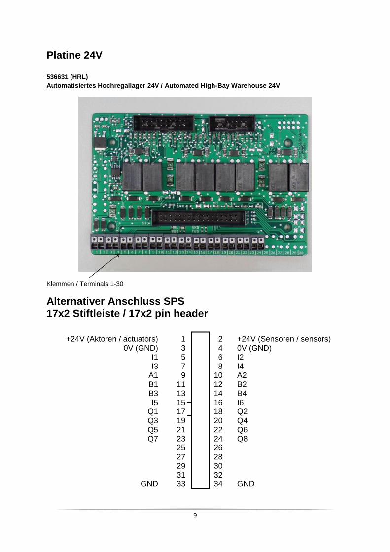
Platine 24V 536631 (HRL)
Automatisiertes Hochregallager 24V / Automated High-Bay Warehouse 24V
Klemmen / Terminals 1-30
Alternativer Anschluss SPS 17x2 Stiftleiste / 17x2 pin header
+24V (Aktoren / actuators) 1 2 +24V (Sensoren / sensors) 0V (GND) 3 4 0V (GND) I1 5 6 I2 I3 7 8 I4 A1 9 10 A2 B1 11 12 B2 B3 13 14 B4 I5 15 16 I6 Q1 17 18 Q2 Q3 19 20 Q4 Q5 21 22 Q6 Q7 23 24 Q8 25 26 27 28 29 30 31 32 GND 33 34 GND

10
Hochregallager Verdrahtung Modell / Warehouse wiring model
Klemme / Terminal
Stiftleiste / pin header ST1
Flachbandkabel/ ribbon cable
Sensoren+Aktoren Modell / Sensors +actuators model
5 Referenz horizontal / reference horizontal 1 I1
2 24V (Sensor) 2
6 Fototransistor innen / phototransistor inside 3 I2
2 24V (Sensor) 4
7 Fototransistor außen / phototransistor outside 5 I3
2 24V (Sensor) 6
17 Förderband vorwärts / conveyor belt forward 7
Q1/Q2 (M1)
18 Förderband rückwärts / conveyor belt backwards 8
3,4 GND 9
Spursensor: Spannungs- Versorgung
A1 (unten), A2 (oben) /
Trail sensor: power supply A1 (down), A2 (top)
2
9V (aus 24V Sensor erzeugt) / 9V (generated from 24V sensor) 10
9 Spursensor1 / trail sensor 1 11
10 Spursensor2 / trail sensor 2 12
3,4 GND 13 Lampen für Lichtschranke / lamps for
light barrier 2 24V (Sensor) 14
19 Motor horizontal zum Regal / motor horizontal towards rack 15
Q3/Q4 (M2)
20
Motor horizontal zum Förderband / motor horizontal to conveyor belt 16
3,4 GND 17 Encoder horizontal Spannungsversorgung /
power supply Signal A Signal B
2 24V (Sensor) 18
11 A 19 12 B 20
Stiftleiste / pin header ST2
8 Referenztaster vertikal / reference switch vertical axis 1 I4
2 24V (Sensor) 2
21 Vertikale Achse runter / vertical axis downward 3
Q6/Q7 (M3)
22 Vertikale Achse hoch / vertical axis upward 4
3,4 GND 5 Encoder vertical Spannungsversorgung /
power supply Signal A Signal B
2 24V (Sensor) 6
13 A 7
14 B 8

11
15
Referenztaster Ausleger vorn / reference switch cantilever front 9
I5
2 24V (Sensor) 10
23 Ausleger vor 11 Q7/Q8 (M4)
24 Ausleger zurück 12
16
Referenztaster Ausleger hinten / Reference switch cantilever back 13 I6
2 24V (Sensor) 14
rot = Spannungsversorgung / red = power supply gelb = Motor über Relais umpolbar / yellow = motor reversable with relays
12
-
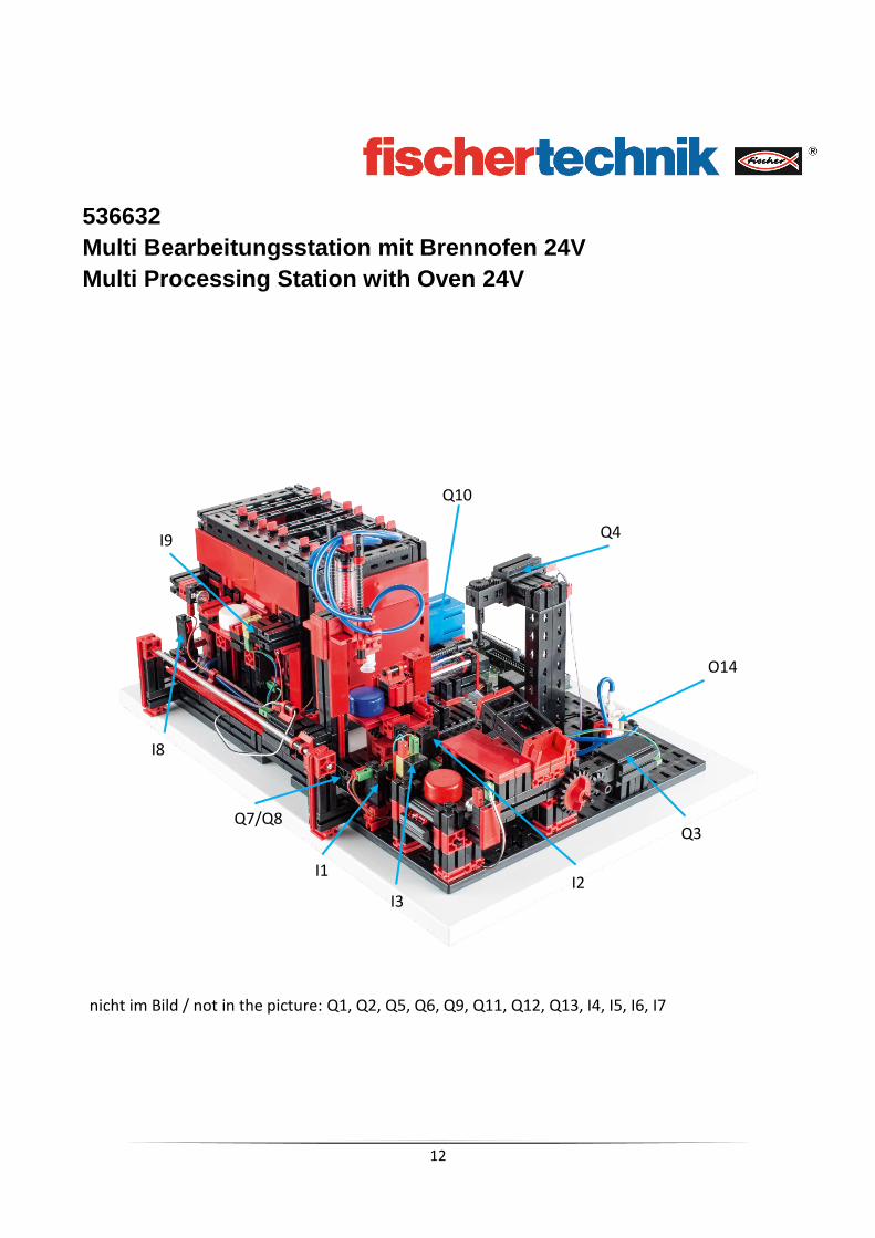
536632
Multi Bearbeitungsstation mit Brennofen 24V
Multi Processing Station with Oven 24V
I4
I1
Q4
Q3
O14
I3 I2
Q7/Q8
I8
I1
I9
nicht im Bild / not in the picture: Q1, Q2, Q5, Q6, Q9, Q11, Q12, Q13, I4, I5, I6, I7
Q10
13
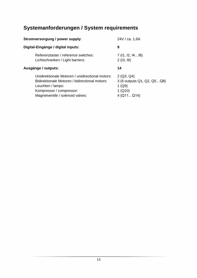
Systemanforderungen / System requirements Stromversorgung / power supply: 24V / ca. 1,6A
Digital-Eingänge / digital inputs: 9
Referenztaster / reference switches: 7 (I1, I2, I4…I8)
Lichtschranken / Light barriers: 2 (I3, I9)
Ausgänge / outputs: 14
Unidirektionale Motoren / unidirectional motors: 2 (Q3, Q4)
Bidirektionale Motoren / bidirectional motors: 3 (6 outputs Q1, Q2, Q5…Q8)
Leuchten / lamps: 1 (Q9)
Kompressor / compressor: 1 (Q10)
Magnetventile / solenoid valves: 4 (Q11…Q14)

14
Systemanforderungen SPS System requirements PLC SPS Eingangs- und Ausgangskonfiguration
PLC input and output configuration
Eingänge / inputs Ausgänge / outputs
Typ / type P-lesend / sinking input P-schaltend / sourcing output
Schaltung /
switching
Systemanforderungen für sonstige Steuerungen System requirements for other controllers
Falls statt einer SPS eine andere Steuerung wie z.B. Arduino verwendet wird, so muss
sichergestellt werden, dass die folgenden Anforderungen erfüllt werden.
- Schnittstelle zu Adapterplatine kompatibel zu 24V
- Zykluszeit von min. 10 ms
If instead of a PLC another controller such as Arduino is used, it must be ensured that the
following requirements are met.
- Interface to adaptor-PCB compatible with 24V
- Cycle time at least 10 ms

15
Belegungsplan für Bearbeitungsstation mit Brennofen 24V
Circuit layout for Multi Processing Station with Oven 24V
Klemme Nr. Terminal no.
Funktion Function
Eingang/Ausgang Input/Output
1 Stromversorgung (+) Aktoren power supply (+) actuators
24V DC
2 Stromversorgung (+) Sensoren power supply (+) sensors
24V DC
3 Stromversorgung (-) power supply (-)
0V
4 Stromversorgung (-) power supply (-)
0V
5 Referenzschalter Drehkranz (Position Sauger) reference switch turn-table (position vacuum)
I1
6 Referenzschalter Drehkranz (Position Förderband) reference switch turn-table (position belt)
I2
7 Lichtschranke Ende Förderband light-barrier end of conveyor belt
I3
8 Referenzschalter Drehkranz (Position Säge) reference switch turn-table (position saw)
I4
9 Referenzschalter Sauger (Position Drehkranz) reference switch vacuum (position turn-table)
I5
10 Referenzschalter Ofenschieber innen reference switch oven feeder inside
I6
11 Referenzschalter Ofenschieber außen reference switch oven feeder outside
I7
12 Referenzschalter Sauger (Position Brennofen) reference switch vacuum (position oven)
I8
13 Lichtschranke Brennofen light-barrier oven
I9
17 Motor Drehkranz im Uhrzeigersinn motor turn-table counterclockwise
Q1 (M1)
18 Motor Drehkranz gegen Uhrzeigersinn motor turn-table counterclockwise
Q2 (M1)
19 Motor Förderband vorwärts motor conveyor belt forward
Q3 (M2)
20 Motor Säge motor saw
Q4 (M3)
21 Motor Ofenschieber einfahren motor oven feeder retract
Q5 (M4)
22 Motor Ofenschieber ausfahren motor oven feeder extend
Q6 (M4)
23 Motor Sauger zum Ofen motor vacuum towards oven
Q7 (M5)
24 Motor Sauger zum Drehkranz motor vacuum towards turn-table
Q8 (M5)
25 Leuchte Ofen light oven
Q9
26 Kompressor Compressor
Q10
27 Ventil Vakuum valve vacuum
Q11
28 Ventil Senken valve lowering
Q12
29 Ventil Ofentür valve oven door
Q13
30 Ventil Schieber Q14

16
valve feeder
Platine 24V
536632 (FBS)
Multi Bearbeitungsstation mit Brennofen 24V
Multi Processing Station with Oven 24V
Klemmen 1-30 / terminals 1-30
Alternativer Anschluss SPS 17x2 Stiftleiste / 17x2 pin header
+24V (Aktoren / actuators) 1 2 +24V (Sensoren / sensors) 0V (GND) 3 4 0V (GND) I1 5 6 I2 I3 7 8 I4 I5 9 10 I6 I7 11 12 I8 I9 13 14 15 16 Q1 17 18 Q2 Q3 19 20 Q4 Q5 21 22 Q6 Q7 23 24 Q8 Q9 25 26 Q10 Q11 27 28 Q12 Q13 29 30 Q14 31 32 GND 33 34 GND

17
Bearbeitungsstation mit Brennofen Verdrahtung Modell /
Processing station wiring model
Klemme Stiftleiste / pin header ST1
Flachbandkabel / ribbon cable
Sensoren+Aktoren am Modell / sensors+actuators model
5 Referenztaster Drehkranz / reference switch turn-table 1 I1
2 24V (Sensor) 2
6 Referenztaster Drehkranz / reference switch turn-table 3 I2
2 24V (Sensor) 4
7
Lichtschranke Ende Förderband / light-barrier end of conveyor belt 5 I3
2 24V (Sensor) 6
17 Drehkranz im Uhrzeigersinn / motor turn-table cw 7
Q1/Q2 (M1)
18
Drehkranz gegen Uhrzeigersinn / motor turn-table ccw 8
3,4 GND 9
Lampe Lichtschranke / lamp light barrier 2 24V (Sensor) 10
9 Referenztaster Sauger / reference switch vacuum 11 I5
2 24V (Sensor) 12
8
Referenztaster Drehkranz Pos Säge / reference switch turn-table position saw 13 I4
2 24V (Sensor) 14
3,4 GND 15 Q3 (M2)
19 Förderband / conveyor belt 16
3,4 GND 17 Q4 (M3)
20 Säge / saw 18
nicht belegt / not used 19
nicht belegt not used 20
ST2
nicht belegt / not used 1
nicht belegt / not used 2
21 Ofenschieber einfahren / oven feeder retract 3
Q5/Q6 (M4)
22 Ofenschieber ausfahren / oven feeder extend 4
10 Ofenschieber innen / oven feeder inside 5 I6
2 24V (Sensor) 6
11 Ofenschieber außen / oven 7 I7

18
feeder outside
2 24V (Sensor) 8
12 Sauger bei Ofen / vacuum position oven 9
I8
2 24V (Sensor) 10
23 Sauger zum Ofen vacuum towards oven 11
Q7/Q8(M5)
24 Sauger zum Drehkranz vacuum towards turn-table 12
3,4 GND 13 Q9 (Leuchte Ofen / lamp oven) 25 Leuchte Ofen / light oven 14
3,4 GND 15 Q10 (Kompressor)
26 Kompressor / compressor 16
13 Lichtschranke Ofen / light barrier oven 17 I9
2 24V (Sensor) 18
3,4 GND 19
Lampe Lichtschranke / lamp light barrier 2 24V (Sensor) 20
3,4 Klemme / terminal V1
Q11 (Ventil Vakuum / valve
vacuum) 27 3,4
Klemme / terminal V2
Q12 (Ventil Senken / valve lowering) 28
3,4 Klemme / terminal V3
Q13 (Ventil Ofentür / valve
oven door) 29 3,4
Klemme / terminal V4
Q14 (Ventil Schieber / valve feeder) 30
rot = Spannungsversorgung / red = power supply gelb = Motor über Relais umpolbar / yellow = motor reversable via relays

19
Schlauchanschlussplan / air line layout plan

20
536633
Sortierstrecke mit Farberkennung 24V
Sorting Line with Detection 24V
I5
I7
I6
I1
I3 A4
I2
Q2
nicht im Bild / not in the picture: Q1, Q3, Q4, Q5
Kupplung zu Multi
Bearbeitungsstation /
coupling to multi
processing station
21
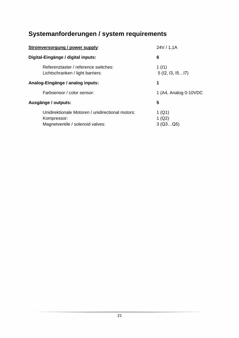
Systemanforderungen / system requirements Stromversorgung / power supply: 24V / 1,1A
Digital-Eingänge / digital inputs: 6
Referenztaster / reference switches: 1 (I1)
Lichtschranken / light barriers: 5 (I2, I3, I5…I7)
Analog-Eingänge / analog inputs: 1
Farbsensor / color sensor: 1 (A4, Analog 0-10VDC
Ausgänge / outputs: 5
Unidirektionale Motoren / unidirectional motors: 1 (Q1)
Kompressor: 1 (Q2)
Magnetventile / solenoid valves: 3 (Q3…Q5)

22
Systemanforderungen SPS System requirements PLC SPS Eingangs- und Ausgangskonfiguration
PLC input and output configuration
Eingänge / inputs Ausgänge / outputs
Typ / type P-lesend / sinking input P-schaltend / sourcing output
Schaltung /
switching
Systemanforderungen für sonstige Steuerungen System requirements for other controllers
Falls statt einer SPS eine andere Steuerung wie z.B. Arduino verwendet wird, so muss
sichergestellt werden, dass die folgenden Anforderungen erfüllt werden.
- Schnittstelle zu Adapterplatine kompatibel zu 24V
- Zykluszeit von min. 10 ms
If instead of a PLC another controller such as Arduino is used, it must be ensured that the
following requirements are met.
- Interface to adaptor-PCB compatible with 24V
- Cycle time at least 10 ms

23
Belegungsplan für Sortierstrecke mit Farberkennung 24V Circuit layout for Sorting Line with Detection 24V Klemme Nr. Terminal no.
Funktion Function
Eingang/Ausgang Input/Output
1 Stromversorgung (+) Aktoren power supply (+) actuators
24V DC
2 Stromversorgung (+) Sensoren power supply (+) sensors
24V DC
3 Stromversorgung (-) power supply (-)
0V
4 Stromversorgung (-) power supply (-)
0V
5 Impulstaster pulse counter
I1
6 Lichtschranke Eingang light-barrier inlet
I2
7 Lichtschranke nach Farbsensor light-barrier behind color sensor
I3
8 Nicht belegt not used
9 Farbsensor color sensor
A4 Analog 0-10VDC
10 Lichtschranke weiß light-barrier white
I5
11 Lichtschranke rot light-barrier red
I6
12 Lichtschranke blau light-barrier blue
I7
17 Motor Förderband motor conveyor belt
Q1
18 Kompressor compressor
Q2
19 Nicht belegt not used
20 Ventil erster Auswurf (weiß) valve first ejector (white)
Q3
21 Ventil zweiter Auswurf (rot) valve second ejector (red)
Q4
22 Ventil dritter Auswurf (blau) valve third ejector (blue)
Q5
24
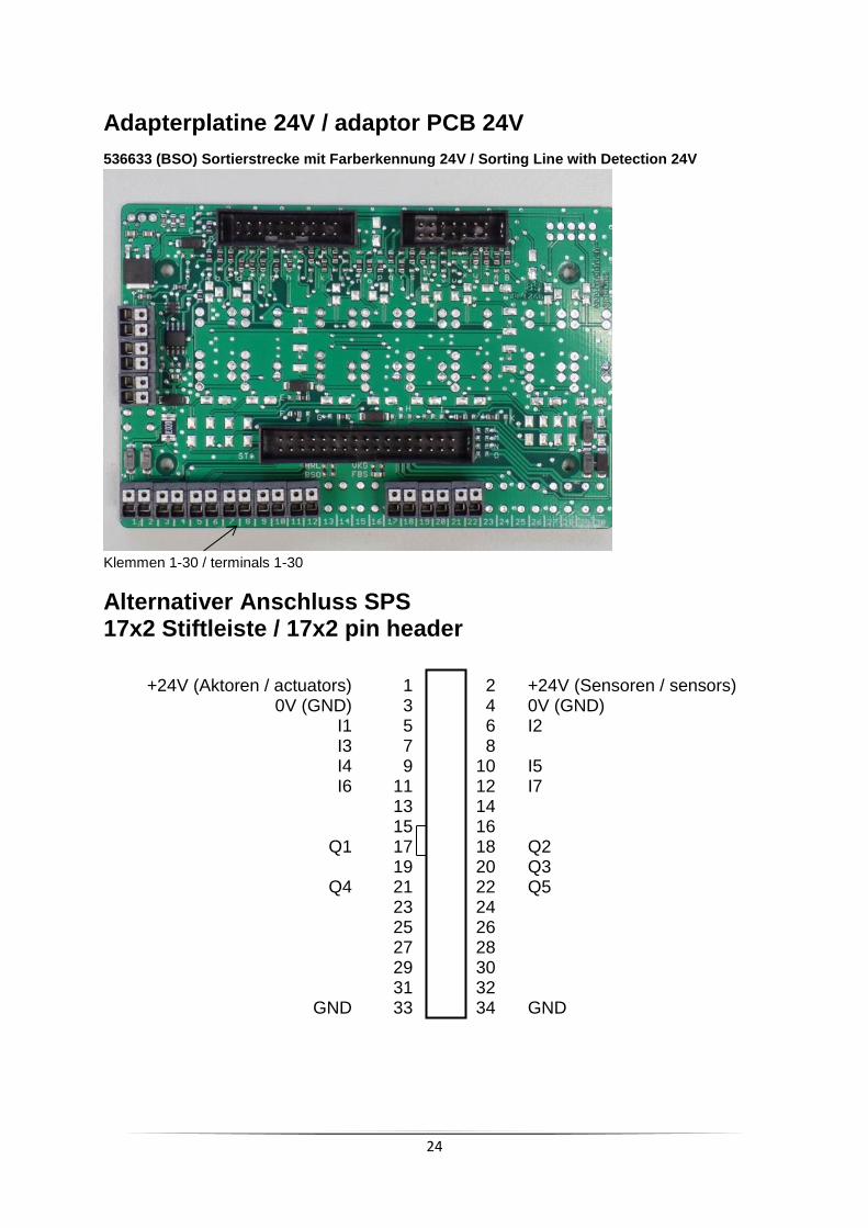
Adapterplatine 24V / adaptor PCB 24V
536633 (BSO) Sortierstrecke mit Farberkennung 24V / Sorting Line with Detection 24V
Klemmen 1-30 / terminals 1-30
Alternativer Anschluss SPS 17x2 Stiftleiste / 17x2 pin header
+24V (Aktoren / actuators) 1 2 +24V (Sensoren / sensors) 0V (GND) 3 4 0V (GND) I1 5 6 I2 I3 7 8 I4 9 10 I5 I6 11 12 I7 13 14 15 16 Q1 17 18 Q2 19 20 Q3 Q4 21 22 Q5 23 24 25 26 27 28 29 30 31 32 GND 33 34 GND

25
Sortierstrecke Verdrahtung Modell / sorting line wiring model
Klemme / terminal Stiftleiste / pin header ST1
Flachbandkabel / ribbon cable
Sensoren+Aktoren Modell / sensors+actuators model
5 Impulstaster / pulse counter 1 I1
2 24V (Sensor) 2
6 Lichtschranke Eingang / light-barrier inlet 3 I2
2 24V (Sensor) 4
7
Lichtschranke nach Farbs. / light-barrier behind color sensor 5 I3
2 24V (Sensor) 6
3,4 GND 7 Q2 (Kompressor)
18 Kompressor 8
3,4 GND 9
Q1(Förderband conveyor belt) 17 Förderband / conveyor belt 10
3,4 GND 11
Farbsensor / color sensor (A4) 2
9V (generiert aus 24V Sensor) / (generated from 24V) 12
9 Farbsensor / color sensor (0-10V) 13
nicht belegt / not used 14
3,4 GND 15 Lampe Lichtschranke / lamp light barrier 2 24V (Sensor) 16
3,4 GND 17 Lampe Lichtschranke / lamp light barrier 2 24V (Sensor) 18
nicht belegt / not used 19
nicht belegt / not used 20
Stiftleiste / pin header ST2
nicht belegt / not used 1
nicht belegt / not used 2
10 Lichtschranke weiß / light barrier white 3 I5
2 24V (Sensor) 4
12 Lichtschranke blau / light barrier blue 5 I7
2 24V (Sensor) 6
11 Lichtschranke rot / light barrier red 7 I6
2 24V (Sensor) 8
3,4 GND 9
Lampe Lichtschranke / lamp light barrier 2 24V (Sensor) 10
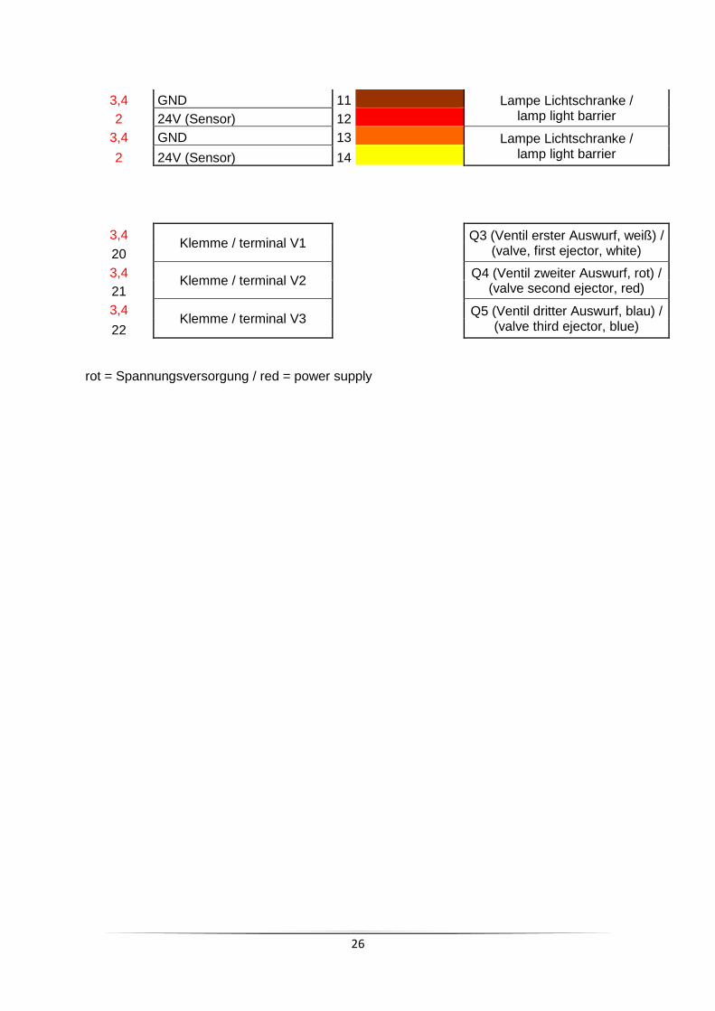
26
3,4 GND 11 Lampe Lichtschranke / lamp light barrier 2 24V (Sensor) 12
3,4 GND 13 Lampe Lichtschranke / lamp light barrier 2 24V (Sensor) 14
3,4 Klemme / terminal V1
Q3 (Ventil erster Auswurf, weiß) /
(valve, first ejector, white) 20 3,4
Klemme / terminal V2
Q4 (Ventil zweiter Auswurf, rot) / (valve second ejector, red) 21
3,4 Klemme / terminal V3
Q5 (Ventil dritter Auswurf, blau) /
(valve third ejector, blue) 22
rot = Spannungsversorgung / red = power supply

27
Schlauchanschlussplan / air line layout plan

28
I2 I3
I1
Q3/Q4 + B3/B4
Q1/Q2+B1/B2
Q5/Q6+B5/B6
Q7 Q8
536630
Vakuum-Sauggreifer 24V
Vacuum Gripper Robot 24V

29
Systemanforderungen / system requirements Stromversorgung / power supply: 24V / ca. 0,9A
Digitale Eingänge / digital inputs: 3
Referenztaster / reference switches: 3 (I1…I3)
Zähl-Eingänge / counter inputs: 6
Encoder: 3 (6 inputs, B1…B6)
Ausgänge / outputs: 8
Bidirektionale Motoren / bidirectional motors: 3 (6 outputs Q1…Q6)
Kompressoren / compressors: 1 (Q7)
Magnetventile / solenoid valves: 1 (Q8)
30
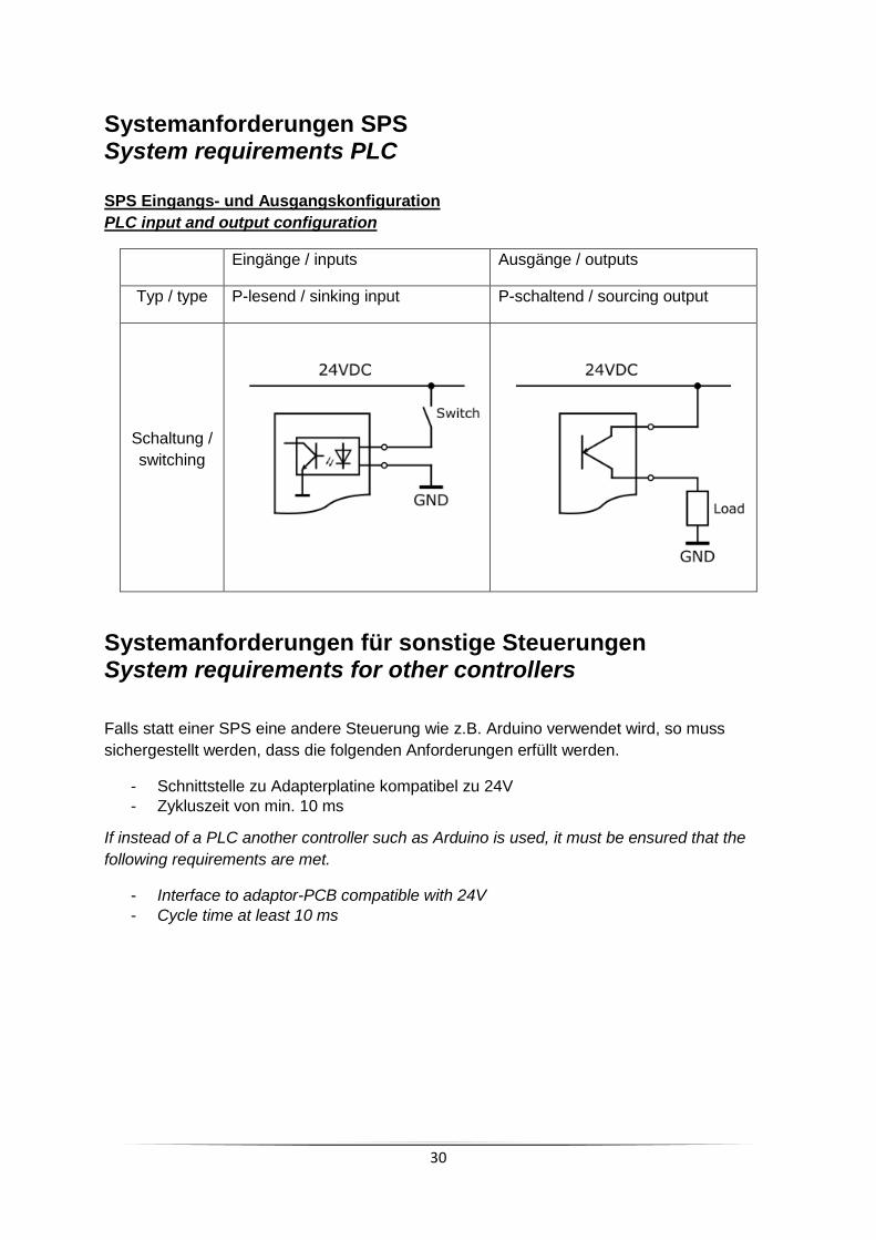
Systemanforderungen SPS System requirements PLC SPS Eingangs- und Ausgangskonfiguration
PLC input and output configuration
Eingänge / inputs Ausgänge / outputs
Typ / type P-lesend / sinking input P-schaltend / sourcing output
Schaltung /
switching
Systemanforderungen für sonstige Steuerungen System requirements for other controllers
Falls statt einer SPS eine andere Steuerung wie z.B. Arduino verwendet wird, so muss
sichergestellt werden, dass die folgenden Anforderungen erfüllt werden.
- Schnittstelle zu Adapterplatine kompatibel zu 24V
- Zykluszeit von min. 10 ms
If instead of a PLC another controller such as Arduino is used, it must be ensured that the
following requirements are met.
- Interface to adaptor-PCB compatible with 24V
- Cycle time at least 10 ms
31
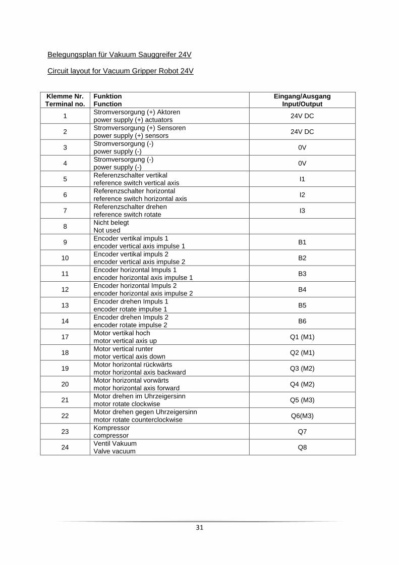
Belegungsplan für Vakuum Sauggreifer 24V
Circuit layout for Vacuum Gripper Robot 24V Klemme Nr. Terminal no.
Funktion Function
Eingang/Ausgang Input/Output
1 Stromversorgung (+) Aktoren power supply (+) actuators
24V DC
2 Stromversorgung (+) Sensoren power supply (+) sensors
24V DC
3 Stromversorgung (-) power supply (-)
0V
4 Stromversorgung (-) power supply (-)
0V
5 Referenzschalter vertikal reference switch vertical axis
I1
6 Referenzschalter horizontal reference switch horizontal axis
I2
7 Referenzschalter drehen reference switch rotate
I3
8 Nicht belegt Not used
9 Encoder vertikal impuls 1 encoder vertical axis impulse 1
B1
10 Encoder vertikal impuls 2 encoder vertical axis impulse 2
B2
11 Encoder horizontal Impuls 1 encoder horizontal axis impulse 1
B3
12 Encoder horizontal Impuls 2 encoder horizontal axis impulse 2
B4
13 Encoder drehen Impuls 1 encoder rotate impulse 1
B5
14 Encoder drehen Impuls 2 encoder rotate impulse 2
B6
17 Motor vertikal hoch motor vertical axis up
Q1 (M1)
18 Motor vertical runter motor vertical axis down
Q2 (M1)
19 Motor horizontal rückwärts motor horizontal axis backward
Q3 (M2)
20 Motor horizontal vorwärts motor horizontal axis forward
Q4 (M2)
21 Motor drehen im Uhrzeigersinn motor rotate clockwise
Q5 (M3)
22 Motor drehen gegen Uhrzeigersinn motor rotate counterclockwise
Q6(M3)
23 Kompressor compressor
Q7
24 Ventil Vakuum Valve vacuum
Q8
32
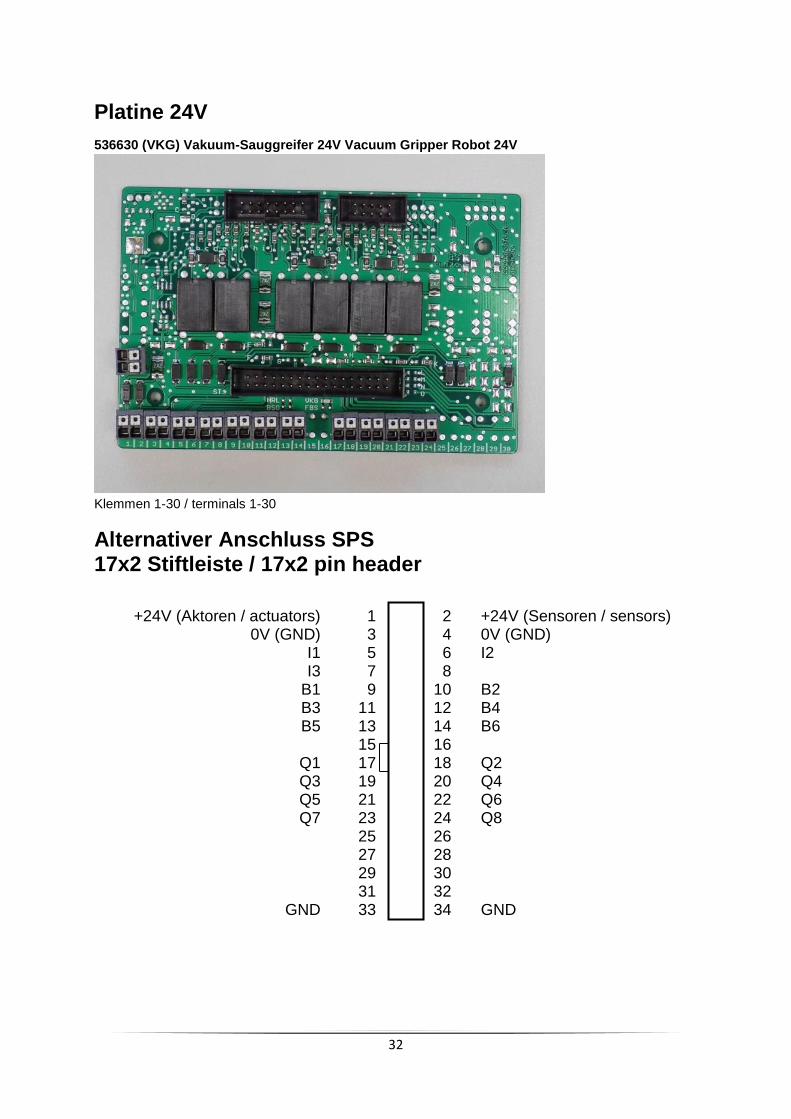
Platine 24V
536630 (VKG) Vakuum-Sauggreifer 24V Vacuum Gripper Robot 24V
Klemmen 1-30 / terminals 1-30
Alternativer Anschluss SPS 17x2 Stiftleiste / 17x2 pin header
+24V (Aktoren / actuators) 1 2 +24V (Sensoren / sensors) 0V (GND) 3 4 0V (GND) I1 5 6 I2 I3 7 8 B1 9 10 B2 B3 11 12 B4 B5 13 14 B6 15 16 Q1 17 18 Q2 Q3 19 20 Q4 Q5 21 22 Q6 Q7 23 24 Q8 25 26 27 28 29 30 31 32 GND 33 34 GND

33
Vakuumsauggreifer Verdrahtung Modell / vacuum gripper wiring model
Klemme / terminal Stiftleiste / pin header ST1
Flachbandkabel / ribbon cable
Sensoren+Aktoren Modell / sensors+actuators model
17 Vertikal hoch / vertical axis up 1
Q1/Q2 (M1)
18 Vertikal runter / vertical axis down 2
3,4 GND 3 Encoder Spannungs-Versorgung /
encoder power supply Signal A Signal B
2 24V (Sensor) 4
9 A 5
10 B 6
5 Referenz vertikal / reference vertical 7 I1
2 24V 8
19 Horizontal zurück / horizontal axis backward 9
Q3/Q4 (M2)
20 Horizontal vor / horizontal axis forward 10
3,4 GND 11 Encoder Spannungs-Versorgung /
encoder power supply Signal A Signal B
2 24V (Sensor) 12
11 A 13
12 B 14
6 Referenz horizontal / reference horizontal 15 I2
2 24V (Sensor) 16
Stiftleiste / pin header ST2
7 Referenz drehen / reference rotate 1 I3
2 24V (Sensor) 2
21 Drehen im Uhrzeigersinn / rotate cw 3
Q5/Q6 (M3)
22 Drehen gegen Uhrzeigersinn / rotate ccw 4
3,4 GND 5 Encoder Spannungs-Versorgung
(encoder power supply) Signal A Signal B
2 24V (Sensor) 6
13 A 7
14 B 8
3,4 GND 9
Q7 (Kompressor) / compressor 23 Kompressor / compressor 10
3,4 Klemme / terminal V1
Q8 (Ventil Vakuum) /
(valve vacuum) 24 rot = Spannungsversorgung / red = power supply
gelb = Motor über Relais umpolbar / yellow = bidirectional motor via relais
34
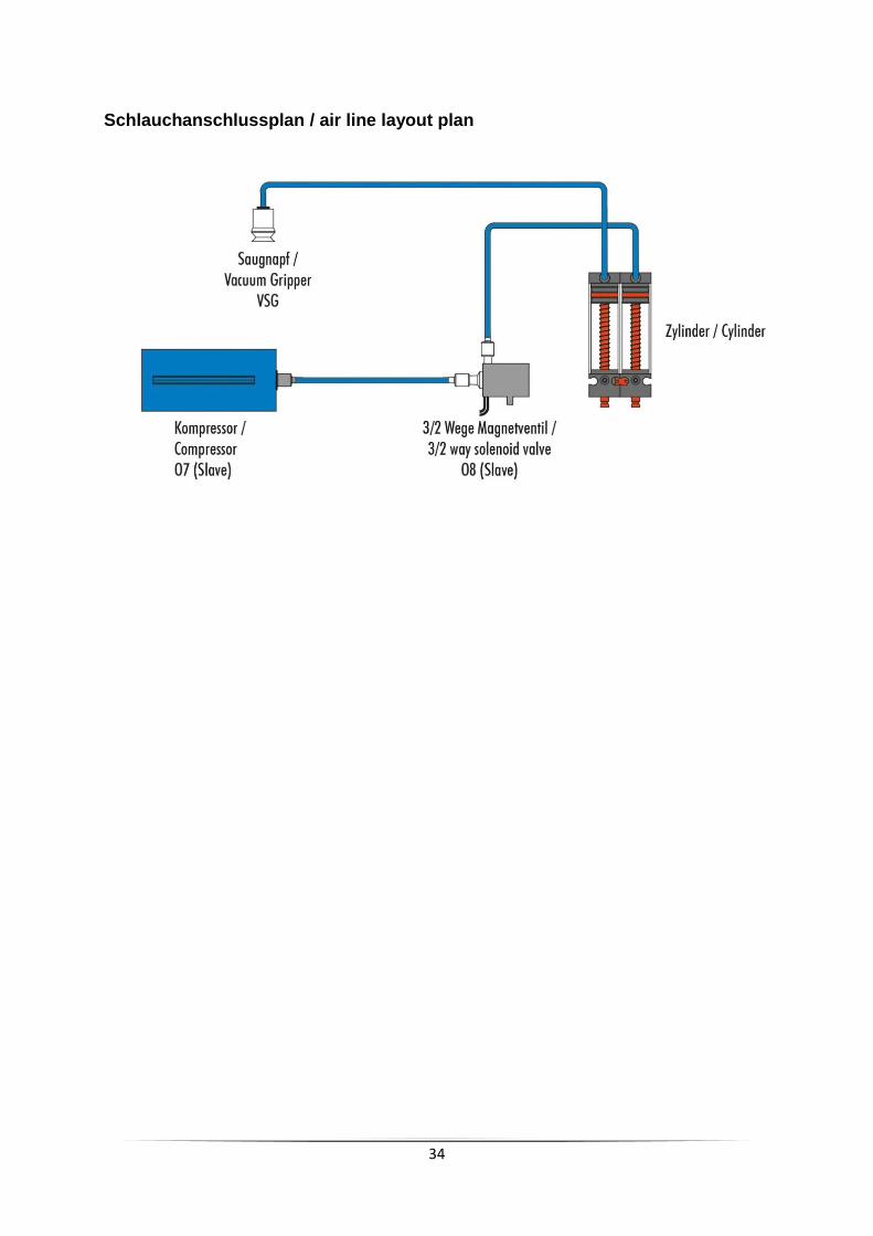
Schlauchanschlussplan / air line layout plan

35
Ersatzschaltbilder für Anschluss Trainingsmodelle an Leiterplatte 24V /
equivalent circuit diagrams to connect training models to adaptor PCB 24V
Die Leiterplatte dient zur Verteilung der Signale von den Anschlussklemmen (Klemme 1…30) zu den
Flachbandkabeln des Modells.
The PCB passes the signals from the terminals 1…30 to the ribbon cables of the models
Legende / legend:
Klemme zum Anschluss von Stromversorgung, Ein- oder Ausgang an die SPS
(Klemme 1…30) /
terminal to connect power supply, input or output to PLC
Interne Stromversorgung (in diesem Fall Sensor) /
internal power supply (in this case sensor)
Stromversorgung / power supply
An Klemmen 1..4 wird die Stromversorgung angeschlossen. /
At terminals 1..4 the power supply will be connected
Klemme 1: +24V für Umpolrelais Motoren (falls vorhanden)
terminal 1: +24V for changeover relays for the motors
Klemme 2: +24V für Sensoren
terminal 2: +24V for sensors
Klemme 3+4: Masse
terminal 3+4: ground
Die intern weitergeführten Stromversorgungen sind gegen Verpolung und Überlast geschützt. /
the internal power supplies are protected against overload and reverse voltage
36
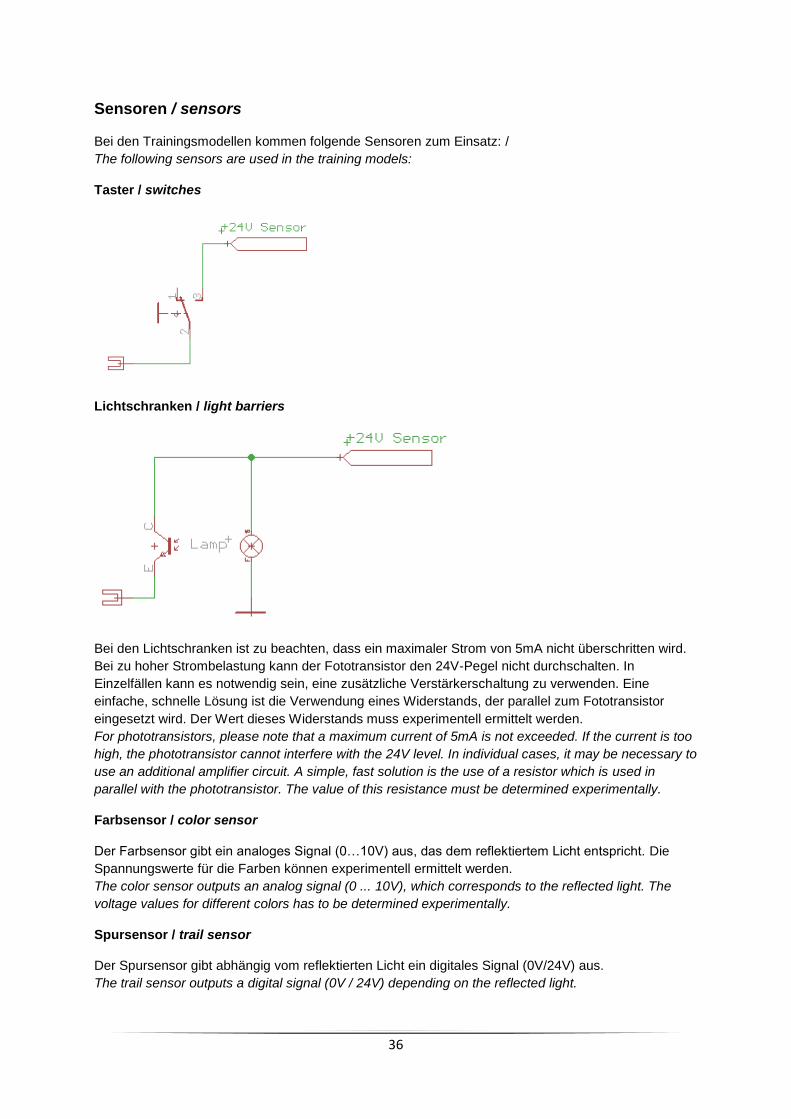
Sensoren / sensors
Bei den Trainingsmodellen kommen folgende Sensoren zum Einsatz: /
The following sensors are used in the training models:
Taster / switches
Lichtschranken / light barriers
Bei den Lichtschranken ist zu beachten, dass ein maximaler Strom von 5mA nicht überschritten wird.
Bei zu hoher Strombelastung kann der Fototransistor den 24V-Pegel nicht durchschalten. In
Einzelfällen kann es notwendig sein, eine zusätzliche Verstärkerschaltung zu verwenden. Eine
einfache, schnelle Lösung ist die Verwendung eines Widerstands, der parallel zum Fototransistor
eingesetzt wird. Der Wert dieses Widerstands muss experimentell ermittelt werden.
For phototransistors, please note that a maximum current of 5mA is not exceeded. If the current is too
high, the phototransistor cannot interfere with the 24V level. In individual cases, it may be necessary to
use an additional amplifier circuit. A simple, fast solution is the use of a resistor which is used in
parallel with the phototransistor. The value of this resistance must be determined experimentally.
Farbsensor / color sensor
Der Farbsensor gibt ein analoges Signal (0…10V) aus, das dem reflektiertem Licht entspricht. Die
Spannungswerte für die Farben können experimentell ermittelt werden.
The color sensor outputs an analog signal (0 ... 10V), which corresponds to the reflected light. The
voltage values for different colors has to be determined experimentally.
Spursensor / trail sensor
Der Spursensor gibt abhängig vom reflektierten Licht ein digitales Signal (0V/24V) aus.
The trail sensor outputs a digital signal (0V / 24V) depending on the reflected light.
37
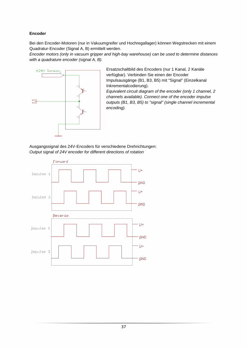
Encoder
Bei den Encoder-Motoren (nur in Vakuumgreifer und Hochregallager) können Wegstrecken mit einem
Quadratur-Encoder (Signal A, B) ermittelt werden.
Encoder motors (only in vacuum gripper and high-bay warehouse) can be used to determine distances
with a quadrature encoder (signal A, B).
Ersatzschaltbild des Encoders (nur 1 Kanal, 2 Kanäle
verfügbar). Verbinden Sie einen der Encoder
Impulsausgänge (B1, B3, B5) mit "Signal" (Einzelkanal
Inkrementalcodierung).
Equivalent circuit diagram of the encoder (only 1 channel, 2
channels available). Connect one of the encoder impulse
outputs (B1, B3, B5) to "signal" (single channel incremental
encoding).
Ausgangssignal des 24V-Encoders für verschiedene Drehrichtungen:
Output signal of 24V encoder for different directions of rotation

38
Aktoren / Actuators
Schaltbare Lampen, Ventile, Kompressor und unidirektionale Motoren werden direkt von der SPS
geschaltet. Zur Entstörung bei induktiven Verbrauchern ist eine Freilaufdiode integriert.
Switchable lamps, valves, compressors and unidirectional motors are switched directly by the PLC. A
free-floating diode is integrated for interference suppression in inductive loads.
Bidirektionale Motoren / bidirectional motors
Motoren, die ihre Drehrichtung wechseln müssen, werden mit einer Relaisschaltung zur Umpolung
angesteuert. Die Relaisschaltung ist (für jeden Motor) durch eine rückstellende Sicherung gegen
Überstrom abgesichert.
Motors which have to change their direction of rotation are controlled with a relay circuit for reversing
the polarity. The relay circuit is protected (for each motor) by a back-up fuse against overcurrent.
Durch Anlegen einer reduzierten Versorgungsspannung an Klemme 1 kann die Versorgungsspannung
der Motoren zur Steuerung der Drehzahl angepasst werden. Da für die Versorgung der Motoren nur
eine Klemme herausgeführt ist, kann die Spannung nur für alle bidirektionalen Motoren gleichzeitig
eingestellt werden.
By applying a reduced supply voltage to terminal 1, the supply voltage of the motors can be adapted
to control the speed. Since only one terminal can be used for supplying the motors, the voltage can
only be adjusted simultaneously for all bidirectional motors.
Begleitmaterial / tutorials
http://www.fischertechnik-elearning.com
Aktor