Embed Size (px)
Citation preview

THIS REPORT HAS BEEN DELIMITED
AND CLEARED FOR PUBLIC RELEASE
UNDER DOD DIRECTIVE 5200.20 ANDNo ftes*TlCroIS ARE IMPOSEo UPON
ITS USE AND DIICLOIUREI
DISTRIBUTION STATEMENT A
APPROVED FOR PUBLIC RILIAIIJ
DISTRIBUTION UNLIMITID,

[e .pro juce 6y
rm ed Services Technilcal1noratn giyDOCUMENT SERVIC CENTER
KNOTT BUILDING, DAYTON, 2, OHIO
Best Avlilable Cp
NF..F

Ii
/.
T/
Technical Report No. 6Contract N6onr-07129
S• NH 017-412
TIlE STUDY OF ALKALI HALIDE• "•o CRYST AL GOUNT ER•S
!.3 .,., . .
"< i

Technical Report No. 6Contract N6onr-07129
NH 017-412
Physics of the Solid StateUniversity of Illinois
Urbana , IllinoisDepartment of Physics
Principal InvestigatorRobert J. Maurer
January 1953
U. S. Department of the NavyOffice of Naval Research
WashinGton, D). C.

A STUDY OF ALKALI HALIDE
CRYSTAL COUNTERS
Edgar Pearlst•ein, Ph.D.
University of Illinois

The object of this work was to study the behavior of electrons
and holes in alkali halides. It was desired to measure the mobili-
ty of electrons and holes, and also to study their production,
their trapping, and the temperature dependence of these processes.
For reasons which are not understood, the results have been largely
negative, although several interesting phenomena have been noticed
which deserve farther investigation.
Method
The experimental method was similar to that used by McKay(l)(2)
in his experiments on diamond, but with certain improvements in
the electronic instruments. The samples studied were in the form
of single crystals and were used in the circuit shown in Figure 1.
In most cases the crystal was a few tenths of a millimeter thick
and about one centimeter square. The electrodes were usually
semi-transparent evaporated layers of aluminum (aluminum wras
chosen because of its small stopping power for cathode rays and
alpha particles), although in the early experiments graphite was
used. The capacitance C in Figure 1 consists of the capacitance
of the crystal, amplifier input circuit, and associated wiring.
The crystals were normally good insulators, so that no current
flowed through the resistor R. However, if ionizing particles
(cathode rays or alpha particles in this case) entered the crystal,
2
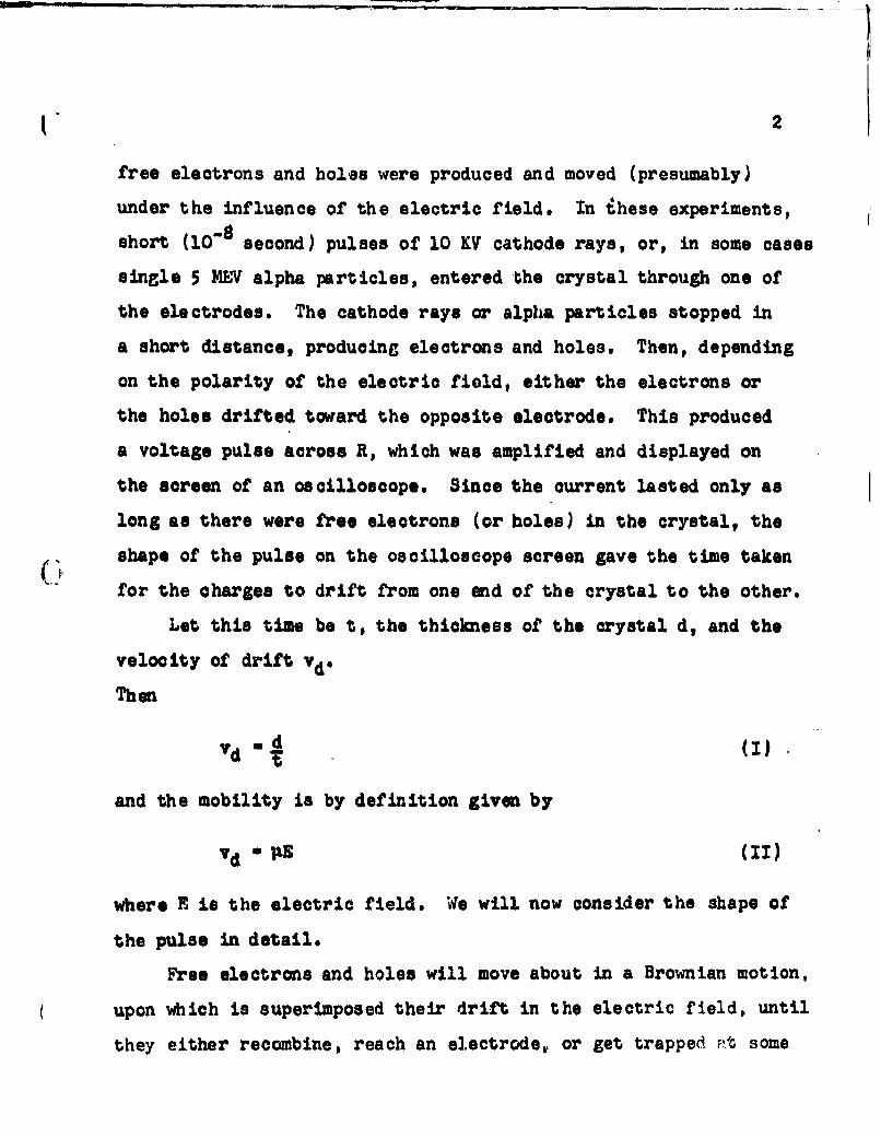
free electrons and holes were produced and moved (presumably)
under the influence of the electric field. In ihese experiments,
short (10-8 second) pulses of 10 KV cathode rays, or, in some cases
single 5 MEV7 alpha particles, entered 'the crystal through one of
the electrodes. The cathode rays or alpha particles stopped in
a short distance, producing electrons and holes. Then, depending
on the polarity of the electric field, either the electrons or
the holes drifted toward the opposite electrode. This produced
a voltage pulse across R, which was amplified and displayed on
the screen of an oscilloscope. Since the current lasted only as
long as there were free electrons (or holes) in the crystal, the
shape of the pulse on the oscilloscope screen gave the time taken
for the charges to drift from one end of the crystal to the other.
Let this time be t, the thickness of the crystal d, and the
velocity of drift vdo
Then
T -(I
and the mobility is by definition given by
Vd - (II)
where E is the electric field. We will now consider the shape of
the pulse in detail.
Free electrons and holes will move about in a Brownian motion,
upon which is superimposed their drift in the electric field, until
they either recombine, reach an electrode, or get trapped Ft some

13
crystal imperfection. We will neglect any direct recombination.
For very small electric fields almost all of the charges will be
trapped before they can get to an electrode, while for sufficiently
large electric fields the drift velocity will be large enough so
that they will almost all reach the electrodes. As long as the
carriers do not reach electrodes, there will be a characteristic
time T for trapping, such that if NO electrons (or holes) are
produced at time sero, then the number remaining at time t will
be
N - Noe(I)
T is given by
T a 1 (IV)
where P is the density of traps, 4r their cross section, and
v the velocity of the electrons in their Brownian motion.
Since the time constant RC, Figare 1, is large compared with
the other times involved, we will consider the pulse from the
standpoint of the charge appearing on the capacitor C. If a
charge q moves in the crystal a distance dx in the direction of
the electric field, then the charge dQ induced on C will be
dQ -4 # CV)d
The signal voltage seen by the amplifier will be
V=1 .X dq (VI)VI

-C -
Since in this case all the charge carriers are produced at
one end of the crystal, only electrons or only holes, depending
on the polarity of the electric field, will give an appreciable
contribution to Q. One can then be sure of working with only one
type of carrier at a time, which is one of the advantages of this
method.
If we put
dx - Vd dt - JEdt (VII)
then
V(t) . _•_.t qdt (VilI)-0
If q - Ne, where N is the number of free electrons (or holes),t
* is the charge of an electron, and N a Noe*'T
then
V _t) E I .t/TVCt - ONo0 f dt , 1TeNo (a -
too (Ix)
This of course is true only if t is small enough go that the
electrons do not reach an electrode: i.e. 'Et 4d. For longer
times
LeN d/xE •"t/T -d 1eT
V -k JN e dt - 1AeO (1-.
t-o (M)

U. 5
This is independent of t, since by this time all the electrons
have either been trapped or have reached an electrode. The
quantity W'- WT is the *Sohubweg".
We then writs
V(tWi N (1 - Omt/T) for t .d (XI)
V~w) (~' U ( e - -dAP for t~ ).d (XII)
The function V(&4?) is plotted in Figure 2. As the electric
field in the crystal increases there is a fsatur ationv of the
pulse height, corresponding to having nearly all the electrons
reach the opposite electrode. The work of Flechsig(4)(5) on
photocurrents in NaCl indicates that saturation can be reached
with crystals of thickness of the order of 0.1 mm. Flecheig's
data gives PT a 5 x 1047 cm2 /volt at room temperature.
By measuring the fPial pulse height V( ') as a function of
E one obtains the product &AT(l1)( 6 .), and by determining the
shape of the pulse one obtains T. In this manner i is obtained.
The shape of the pulse is characterized by the "rise time",
which is defined as the time it takes for the pulse to rise from
10 jo to 90 07o of its final value. From equation XI it is
easily shown that for "' (ý d, the rise time is
tlO090 - T in 9 - 2.2T (XIII)
6
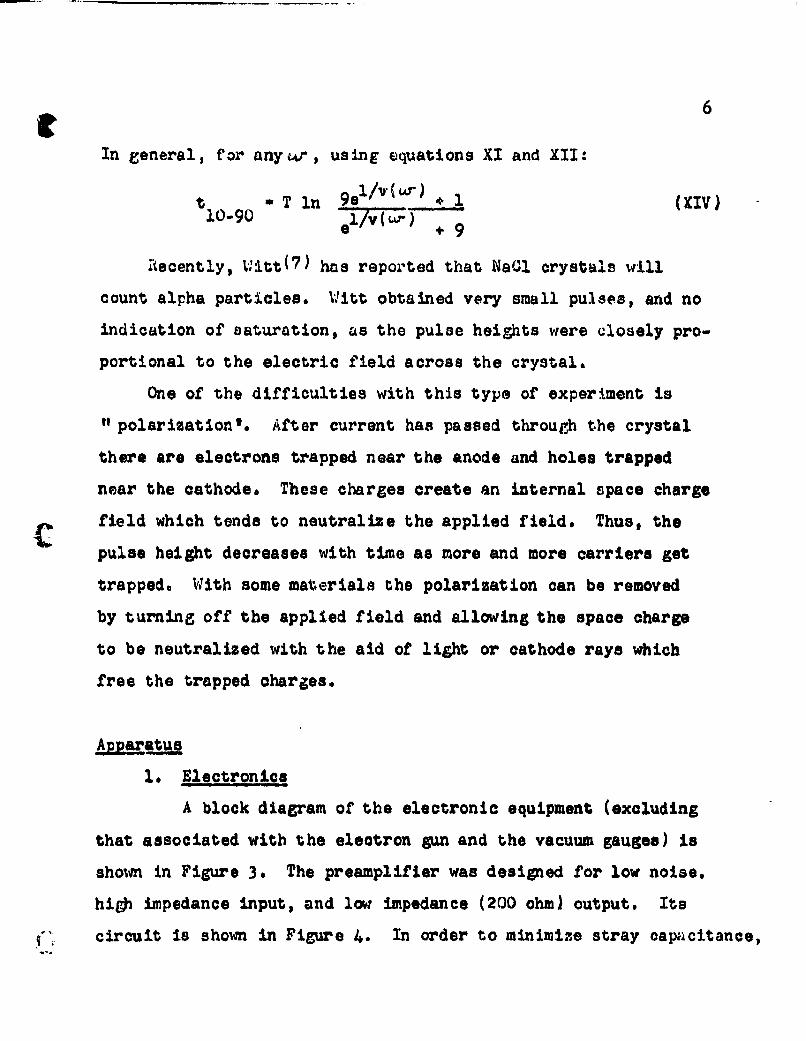
In general, for anyw, using equations XI and XII:
t -T In 9el (I±) . 1 (XIV)10-9 l/v (,..) ,9
Recently, j:itt(?) has reported that Na~l crystals will
count alpha particles. W:Titt obtained very small pulses, and no
indication of saturation, as the pulse heights were closely pro-
portional to the electric field across the crystal.
One of the difficulties with this type of experiment is
"polarization'. After current has passed through the crystal
there are electrons trapped near the anode and holes trapped
near the cathode. These charges create an internal apace charge
field which tends to neutralize the applied field. Thus, the
pulse height decreases with time as more and more carriers get
trapped. With some materials the polarization can be removed
by turning off the applied field and allowing the space charge
to be neutralized with the aid of light or cathode rays which
free the trapped charges.
1. Electronics
A block diagram of the electronic equipment (excluding
that associated with the electron gun and the vacuum gauges) is
shown in Figure 3. The preamplifier was designed for low noise.
high impedance input, and low impedance (200 ohm) output. Its
¶-" circuit is shown in Figure 4. In order to minimize stray capicitance,

c7the preamplifier was mounted inside the vacuum chamber, close to
the crystal holder. For heat dissipation, the tubes were supported
by being waxed with Apiezon W into holes in a piece of 1/16 inch
thick aluminum. The 0.57 I•fd capacitor shown in Figure 4 enables
calibration of the circuit directly in terms of charge appoaring
on the grid of the first tube by applying a step function signal
of known voltage throuLt this capacitor.,
The overall sensitivity of the amplifiers is such that about
8.5 x 10"15 coulombs on the grid of the first preamplifier tube
gives a deflection of one centimeter on the oscilloscope screen,
at full gain. This of course depends to some extent on the
capacitance of the crystal in the holder. The waveform response
is such that a step function pulse at the input of the preampli-
fier gives a pulse on the oscilloscope screen with a rise time
of about 10"S second. This is in good agreement with what would
be expected from the calculated characteristics of the preamplifier
and the advertised characteristics of the liewlett-Packarck ampli-
fiers and the Tektronix oscilloscope. The noise in the amplifiers
corresponds to about three millimeters deflection on the oscilloscope.
The peak reading vacuum tube voltmeter is used for pulse
height measurements, since this is more convenient and more
sensitive than measuring the pulse height directly on the oscillo-
scope screen. The scalar is used as an extra visual and audio
indication of correct functioning, and also, by use of a pulse
height discriminator, to detect pulses which might be barely above
the noise level.

2. Experiment Chamber
A cross section sketch of the vacuum chamber is shown
in Figure 5. The chamber has three removable ports, four inches
in diameter; one is used for the electron gun, and the others
for quartz windows through which the crystal can be illuminated.
One of the ports also has a vacuum seal with a rotatable shaft
which enables a piece of polonium foil to be brought in front
of the crystal in order to test for alpha pawticle counting.
The top and bottom plates are also removable. On the top plate
are attached the crystal holder, preamplifier, and electrical term-
inals. There is a tube on the bottom plate which may be dipped
in liquid nitrogen so that vapors may be trapped before they can
condense on the crystal or the high voltage insulators.
The crystal holder is shown in Figure 6. The electron beam
enters the crystal from the left through a hole in the holder.
The holder is surrounded by a radiation shield which is not shown
in the drawing.
All of the experiments were carried out in a vacuum of 10" mm
Hq or better.
3. Electron Gun
The electron gun was taken from a Duwiont tyl.e I GPl cathode
ray tube and modified by placing the original oxide coated cathode
with a filament of 0.005 inch thoriated tungsten. This is
necessary in order to avoid *poisoning" of the cathode when air
is let into the system between experiments. The modification
was done by Mir. Allen B. Wilson of the Electrical Engineering
Research Laboratory.

(79
The gun is used with about 1400 volts between the filament
and second anode, and ten kilovolts between filament and ground.
The focus, intensity, and positioning circuits are conventional
for this type of tube, the filament current can be varied by means
of a Variao in the primary of the filament transformer. The
maxivwm beam current is about one microampere. The beam is pulsed
by applying to the grid of the gun a positive pulse of about 50
volts and about 5 x 10⁻⁴ second duration.
4. Pulse Generator
The basic pulse eenorator circuit is shown in Figure 7.
The Western Electric 2750 relay has contacts which are wet with
(i• mercury and in a high pressure hydrogen atmosphere in order to
allow very fast make and break. The relay is used without any
modification. It oporates sixty times per second.
The pulse generator gave pulses with rise time less than
7 x 10'9 second, which is the rise time of the oscilloscope ampli-
fier. It was used for testing and calibruiting the apparatus, as
well as to trigger the electron Lun and the oscilloscope sweep.
A similar, but more refined, pulse generator has been des-
cribed in the literature by Oarwin.(b)
Results
In eoneral, the conclusions Which may be drawn from the
experiments are qualitative. In many oases the results could not
be repeated very well at different times and with different
crystals. Possible reasons for this are:

(I 10
(1) Polarization. Because of the poor rerroducibility,
one could not be very sure that the cry-tals we:,e
completely unpolarized. A dependable method for
depolarizing them was not found.
(2) Fonmation of traps. Sombardnment of a crystal with
cathode rays and ultraviolet light for extended times
might produce vacancies and/or coagulations of vacancies
which could trap electrons and holes.
(3) Filling and emptying of traps. Freed electrons and
holes could fill traps and thus change the schubweg.
These traps might then empty out thermally, giving
an additional time dependence of the schubweg.
(4) Ionic conductivity. Appreciable ionic condu.;ivity
oould contribute to polarization and formation of
traps when the electric field is left on for sufficient
time. It is thought that the conductivity is not high
enough at room temperature and below to do much in the
few minutes' time that the field was usually left on.
(5) Cold work and annealing. Repeated handling, cooling,
and warming of a crystal could change its state of cold
work and thus change the schubweg. In a few cases
crystals were annealed and then tried. Although this
data is very meager, no differences were found between
annealed and unannealed specimens.
(6) Surface effects. Since the cathode rays penetrate only
about 10"• cm., minute cracks and dislocations might
influence the number of electrons and holes which can

( 1
get into the body of the crystal. Future experiments
probably should be done with higher energy cathode rays.
Because of the poor reproducibility, the apparatus was
checked frequently with either no crystal in the holder or with a
diamond in the holder. Diamond was used because the author has
had considerable experience with it(9) and data on polarization,
pulse heights, etc. can be reproduced very well with it. From
these checks it was concluded that the effects reported below are
ascribable to the crystals and not to the apparatus.
Results with Alpha Particles
The following alkali halides were tested for alpha pur-
ticle counting: KI, NaI, LiF, KC1, NaC1, and KBr. None of them
Cave detectable pulses except NaI. A description of the results
%Jith Nal follows.
Two crystals, about 0.35 mm thick, were cleaved from the
same laree crystal. The faces were coated with "Dag* dispersion
no. 154 (colloidal graphite in alcohol). At liquid n1trogen tem-
perature both crystals counted individual alpha particles, with
about 1000 volts applied. The pulses were of abouu* - .1 size
for either polarity of applied electric field, indicating that
electrons and holes could be made to move about equally. The
pulse heights wore such that it takes at most 200 e.v. of energy
to produce one free electron-hole pair. At room temperature one of
the crystala did not seem to count at all. The other counted by
means of electron conduction about as well as it did at tha low

12
tempirature, but counted somewhat more weakly by means of hole
conduction.
There was no indication of any gamma ray counting from a
6 mc. radium source held about five inches from the crystal.
Results with Cathode Kays
In most cases the cathode ray pulses were of about 10"I14
coulomb and lasted for 10-8 second. This was measured by allowing
the pulsed beam to fall on the crystal holder with nothing between
the electrodes. This figure does not take into account elastic
reflection of the incident electrons. However, by putting pDsitive
potentials of up to 5000 volts on the crystal holder and noting
the increase in pulse size, it was determined that inelastically
reflected electrons were no more than about twenty percent of
the total.
Sodium Iodide. Three specimens of 1aI were tested for response
to cathode ray pulses. Their thicknesses were 0.25 mm., 0.45 mm.,
and 0.32 mm., respectively. The first had gaphite electrodes,
uhile the other two had evaporated aluminum electrodes. Experi-
ments were done at room temperature and, with liquid nitrogen
coolant, at about -1650 C, as measured by a thermocouple attached
to the crystal holder*
At both temperatures there were conduction pulses with either
direction of electric field, indicating that both electrons and
holes are mobile. At the low temperature the largest pulses were
for electron conduction, while at room temperature the largest were
for hol.' conduction. (This is in disagreement with the re•,.1is for

13
alpha particle counting. Since the alphas penetrate about ten
times as far as the cathode rays, it may be that this disagreement
is due to different temperature dependence of surface effects for
electrons and holes.) In all cases the pulses were small--of the
order of magnitude of one electron or hole for each incident electron.
Electron pulses were about the same at both temperatures. At low
temperature the hole pulses were about one'W'fourth as high as the
electron pulses, while at room temperatures they were about four
times as high as the electron pulses.
The pulse heights seemed to be independent of the electric
field, at least for voltages across the crystal of the order of
300 or preater. The rise time of the pulses was in all cases
less than or equal to 10'8 second (the rise time of the apparatus).
These results seem to indicate that the free electrons and
holes cannot move farther than about 3 x l0'5 cm. in the crystal.
For if one assumes that each incident 10 KI electron produces
about one thousand free pairs, then from the size of the pulse
these secondaries must move only a thousandth of the thickness of
the crystal before being trapped. (This is less than the penetration
depth of the cathode rays )
Since this occurs in a time of 10-8 second or less, the
drift velocity can be as small as 3 x 103 cm/sec, which, for an
electric field of 104 volt/cm. would mean a mobility of about
0.3 m=2/volt sec. Since the 'saturation" field, the time, and
the number of carriers might be considerably overestimated, the
value of the mobility might be considerably greater than indicated
above.

14
The NaI showed fairly defi1nite polarization effects. If a
crystal had been counting cathode rays by means of electrons for
some time and the applied field was then turned off, there were
pulses i.n the opposite direction, gradually decreasing in size,
for several seconds, indicating a space charge field. The anal-
ogous situation occurred if the crystal was originally counting
by means of holes. It appeared that the crystal could be depolarized
by light from a Hanovia high pressure mercury arc, or an infra-
red heat lamp (of the type sold in drug stores), or by a steady
cathode ray beam. There was some evidence for a greater ('-050 06o)
schubweg when the crystal was illuminated by either lamp) than
when in the dark. There were no detectable (7 5 x 10"10 ampere)
steady photocurrents with either of the light sources.
Potassi Chlgrd. Six specimens of Kc1, with thicknesses from
about 0.2 mm. to 0.4 mm. were tested. They all had evaporated
aluminum electrodes. The behavior was very erratic, and one of
the specimens rave no response at all. Several of the crystals
had been annealed at 6000 0; they were then soft enough so that
they could oasily be bent once through a right angle, after which
they became work hardened and brittle again. No differences were
noticed between the annealed and unannealed crystuls.
The crystals gave small electron pulses at both temperatures.
Hole pulses were even smaller and more erratic, at room temperature;
there did not seem to be any hole pulses at the low temperature.
Some polarization effects were noticed. The material could be
depolarized by the mercury arc (but not very dependably) or by a
steady cathode ray beam.,

15
Potassium Bromide. Five crystals of KBr were used. They were
out from the same large crystal and had evaporated aluminum elec-
trodes. Their thicknesses ranged from 0.38 to 0.86 mm. Of these,
two (the thinnest and the thickest) gave fairly reproducible results
and two behaved more erratically. The other one gave very little
response compared to the others, end m*s not studied thoroughly.
No hole motion'was ever detected; the following results apply to
electron motion.
Maxiumum pulse sizes were large; in most cases five to tan
times as large as for the other materials, but in one case eighty
times as large. In addition, it was found that under some con-
ditions the rise times were long, and the mercury light had a
very pronounced effect on both the size and shape of the pulses.
Experiments were done at room temperature and at liquid nitrogen
temperature. No significant differences were found, except that
at room temperature the behavior was more erratic.
Pulses were comparatively large, as mentioned above, and the
rise times were long--of the order of 0.2 microsecond. There was
polarization, as evidenced by decreasing pulse height after a few
seconds. Depolarization could be affected by light from the mercury
lamp, with the applied field turned off. It was necessary to illum.
inate for a minute or so to get the most depolarization, but this
was not very dependable. No pulse height versus applied field
measurements could be taken because of the depolarization diffi-
culties, but it appeared that larger pulses resulted from higher
fields at least up to 4500 volts across the crystal thickness.

(1 16
If light from the mercury lamp was shcne on the crystalwhile the filjd was on, the pulse height would increase by a
factor ranging*om 1.5 to 10, and simultaneously the rise time
would decrease to 10-8 second ) This took about ten seconds, and
one could watch on the oscilloscope screen the pulses gradually
getting larger and sharper. There was little or no change of pulse
height with time in this state. The light could be removed, and
the crystal would remain in this state. It. could be put back into
its previous, long rise time, state by turning off the field and
illuminating with the light for a minute or so. Insufficient
illumination here would leave a crystal in a state such that the
pulses would rise part way in a very short time, and then slowly
the rest of the way. The transition back and forth between the
two states could be repeated indefinitely. If, while in the short
rise time state, the applied field was turned off, the pulse
height would not decrease to zere immediately, but would decrease
to about one-half its original value (in the same direction) imedl-
ately, and then slowly f,'30 seconds) to zero. In the long rise
time state it would go to zero immediately. These things could
all be repeated also with smaller (about one-fifth) initial
cathode ray pulses.
If the light was passed through a filter cutting out wave-
lengths below about 5300A (Corning 3-69), it would still take the
crystal from the slow to the fast rise time state, but not as
quickly and maybe not as completely as the light from the bare
mercury arc. However. the litlt of wavelength above 5100A would
not take the crystal from the fast to the slow rise time •atj.

17
Photocurrents of about 5 x 10"9 ampere could be obtained
with liEht fron the bare mercury arc. then the light passed through
filters cutting off at 4200A or 5300A the current was about
halved. A filter cutting off at 6400A cut the photocurrent to
about one tenth its maximum value. A piece of pyrex glass 2mm.
thick cut the current to about two-thirds its maximum value.
From this it appears that the most effective light is the green
line, 5461A. This is within the F band of KBr. Although no
change of photocurrent with time was noticed, possibly because
the galvanometer used has a period of five seconds, there was
polarization; if one allowed photocurrent to flow, then covered
C-t the light and turned off the field, then uncovered the light, there
was current in the opposite direction--indicating a space charge
field in the crystal.
The above results seem to be consistent with the following
model. From the pulse heights, the sohubweg must be about one
two-hundredth the thickness of the crystal, or about 3 x 10Q" cm.
If now photocurrent is passed through the crystal, it becomes
polarized. We now assume that in this polarized state most of the
potential drop is in the vicinity of the cathode, where the primary
electrons enter. This corresponds to a positive space charge in
the crystal. If this region of high field is several times larger
than the original schubweg, the now schubweg will be this dis-
tance because of the extremely high electric field, and the pulse
height will be larger. Also, the rise time of the pulses will be
many times smaller, since the high field will mean a larger drift
velocity.
A possible explanation for the lack of hole pulses may be
the following. KBr was the only material tested which gave photo-
currents, and it is likely that these currents were due to F centers.
The work of Dutton(10) indicates that holes in KBr may be captured
and annihilated by F centers. It may be that this is .,hat happens
to the holes in this experiment.
One can make the same rough calculation for mobility in KBr
as was made above for Nal. Assume that the electrons (in the long
rise time state) travel 3 x 10i4 cm. in 10-7 second with a field
of 105 volt/cm. The mobility is then 3 x 102 cm2/sec.-volt.
This of course should be regarded as a lower limit.

Footnotes
(1) McKay: Phys. Rev., B, 1606 (1948).
(2) McKay: Phys. Rev. , U7 816 (1950).
(3) This can be derived very easily by conservation of energy.
(4) Flecheig: Zeitz. f. Phys, ., 788 (1928).
(5) Flechaig: Phys. Zeits., 9L, 843 (1931).
(6) See also Mott and Gurney, Electronic Processes in IonicCrystals, p. 122.
(7) Witt: Zeits. f. Phys. 128, 442 (1950).
(8) Garwin: kiev. Sci. Inst., _1, 903 (1950).
(9) Final Report, Navy Contract N7-onr-303, T.O. 5 Part II(1950), Carnegie Institute of Technology.
(10) D. B. Dutton. Thesis, University of Illinois, 1952.

THIN ELECTRODES
CATHODE RAYS TO AMPLIFIJER
AND .,COPE
S--1- -
R
BASIC CiRCUIT FOR CRYSTAL
,~~~~~ FG U RE ...-f .......

(I
u-iccc�L)
�Y)
'I
3
N
o�. '.0 �4)

0
LU
-I -J
ccit
0 -7
Cd.)
2 .u
CL

II, 7
INC
ci
A**
uL

cifN'f x -
0~ (-0l
3C
Zu
Ji)

4u
w
0~
0 00J 4!CLL C
I--w <tjw
CC
V)
uh

LUw
LUU
- 40
w
w~ 0lo
wwuJ
LuLw z
wk
<V
w 4
%A


![23.09.2016. Протокол эл. голосования. ГПД[1]€¦ · rocyÒapcmeeHHoe õzoòowem,qoe oõu,geoõpæoeameJ1bHoe eopoòa MOCR6bZ NCI 797 1--1eT HeT PemeHue 60J1bUIHHCTBOM](https://img.dokumen.tips/doc/110x75/600a56ea47e0d868417e422f/23092016-1-rocyapcmeehhoe.jpg)