Embed Size (px)
Citation preview

Centrifugal Pump
Emporia CP
Installation/Operating Manual

Legal information/Copyright
Installation/Operating Manual Emporia CP
Original operating manual
All rights reserved. The contents provided herein must neither be distributed, copied, reproduced,edited or processed for any other purpose, nor otherwise transmitted, published or made available to athird party without the manufacturer's express written consent.
Subject to technical modification without prior notice.
© KSB SE & Co. KGaA, Frankenthal 09/01/2018
Contents
3 of 40Emporia CP
Contents
Glossary .................................................................................................................................................. 5
1 General.................................................................................................................................................... 61.1 Principles ........................................................................................................................................................... 61.2 Installation of partly completed machinery.................................................................................................... 61.3 Target group..................................................................................................................................................... 61.4 Other applicable documents............................................................................................................................ 61.5 Symbols ............................................................................................................................................................. 6
2 Safety...................................................................................................................................................... 72.1 Key to safety symbols/markings....................................................................................................................... 72.2 General.............................................................................................................................................................. 72.3 Intended use ..................................................................................................................................................... 82.4 Personnel qualification and training............................................................................................................... 82.5 Consequences and risks caused by non-compliance with this manual ......................................................... 82.6 Safety awareness .............................................................................................................................................. 92.7 Safety information for the operator/user ....................................................................................................... 92.8 Safety information for maintenance, inspection and installation ................................................................ 92.9 Unauthorised modes of operation.................................................................................................................. 9
3 Transport/Temporary Storage/Disposal............................................................................................. 103.1 Checking the condition upon delivery .......................................................................................................... 103.2 Transport......................................................................................................................................................... 103.3 Storage/preservation...................................................................................................................................... 113.4 Return to supplier........................................................................................................................................... 113.5 Disposal ........................................................................................................................................................... 12
4 Description of the Pump (Set) ............................................................................................................. 134.1 General description ........................................................................................................................................ 134.2 Product Information as per Regulation No. 547/2012 (for water pumps with a maximum shaft power of
150 kW) implementing "Ecodesign" Directive 2009/125/EC........................................................................ 134.3 Designation..................................................................................................................................................... 134.4 Name plate...................................................................................................................................................... 144.5 Design details.................................................................................................................................................. 144.6 Configuration and function........................................................................................................................... 154.7 Noise characteristics ....................................................................................................................................... 154.8 Scope of supply............................................................................................................................................... 154.9 Dimensions and weights ................................................................................................................................ 15
5 Installation at Site ................................................................................................................................ 175.1 Checking the site before installation ............................................................................................................ 175.2 Installing the pump set .................................................................................................................................. 175.3 Piping .............................................................................................................................................................. 17
5.3.1 Connecting the piping....................................................................................................................... 175.3.2 Permissible forces and moments at the pump nozzles.................................................................... 18
5.4 Electrical connection ...................................................................................................................................... 185.5 Checking the direction of rotation................................................................................................................ 20
6 Commissioning/Start-up/Shutdown................................................................................................... 216.1 Commissioning/Start-up................................................................................................................................. 21
6.1.1 Prerequisites for commissioning/start-up ......................................................................................... 216.1.2 Priming and venting the pump......................................................................................................... 216.1.3 Start-up............................................................................................................................................... 216.1.4 Checking the shaft seal...................................................................................................................... 226.1.5 Shutdown ........................................................................................................................................... 22
6.2 Operating limits.............................................................................................................................................. 236.2.1 Ambient temperature........................................................................................................................ 236.2.2 Frequency of starts............................................................................................................................. 236.2.3 Maximum operating pressure ........................................................................................................... 24
Contents
4 of 40 Emporia CP
6.2.4 Fluid handled ..................................................................................................................................... 246.3 Shutdown/storage/preservation .................................................................................................................... 246.4 Returning to service ....................................................................................................................................... 25
7 Servicing/Maintenance........................................................................................................................ 267.1 Safety regulations........................................................................................................................................... 267.2 Servicing/inspection........................................................................................................................................ 27
7.2.1 Supervision of operation ................................................................................................................... 277.3 Drainage/cleaning .......................................................................................................................................... 287.4 Dismantling the pump set.............................................................................................................................. 28
7.4.1 General information/Safety regulations........................................................................................... 287.5 Reassembling the pump set ........................................................................................................................... 29
7.5.1 General information/Safety regulations........................................................................................... 297.6 Tightening torques......................................................................................................................................... 307.7 Spare parts stock............................................................................................................................................. 30
7.7.1 Ordering spare parts.......................................................................................................................... 30
8 Trouble-shooting.................................................................................................................................. 31
9 Related Documents .............................................................................................................................. 339.1 Exploded view and list of components ......................................................................................................... 33
10 EU Declaration of Conformity ............................................................................................................. 35
11 EU Declaration of Conformity ............................................................................................................. 36
12 Certificate of Decontamination........................................................................................................... 37
Index ..................................................................................................................................................... 38

Glossary
5 of 40Emporia CP
Glossary
Certificate of decontaminationA certificate of decontamination is enclosed by thecustomer when returning the product to themanufacturer to certify that the product has beenproperly drained to eliminate any environmentaland health hazards arising from components incontact with the fluid handled.
Close-coupled designMotor directly fitted to the pump via a flange or adrive lantern
Discharge lineThe pipeline which is connected to the dischargenozzle
PumpMachine without drive, additional components oraccessories
Pump setComplete pump set consisting of pump, drive,additional components and accessories
Suction lift line/suction head lineThe pipeline which is connected to the suctionnozzle
1 General
6 of 40 Emporia CP
1 General
1.1 PrinciplesThis operating manual is supplied as an integral part of the type series and variantsindicated on the front cover. The operating manual describes the proper and safe useof this equipment in all phases of operation.
The name plate indicates the type series and size, the main operating data, the ordernumber and the order item number. The order number and order item numberuniquely identify the pump (set) and serve as identification for all further businessprocesses.
In the event of damage, immediately contact your nearest KSB service centre tomaintain the right to claim under warranty.
Noise characteristics see (ð Section 4.7, Page 15)
1.2 Installation of partly completed machineryTo install partly completed machinery supplied by KSB refer to the sub-sections underServicing/Maintenance.
1.3 Target groupThis operating manual is aimed at the target group of trained and qualified specialisttechnical personnel. (ð Section 2.4, Page 8)
1.4 Other applicable documents
Table 1: Overview of other applicable documents
Document Contents
Data sheet Description of the technical data of the pump (set)
General arrangement drawing/outline drawing
Description of mating dimensions and installationdimensions for the pump (set), weights
Hydraulic characteristic curve Characteristic curves showing head, NPSHrequired, efficiency and power input
General assembly drawing1) Sectional drawing of the pump
Spare parts lists1) Description of spare parts
List of components1) Description of all pump components
For accessories and/or integrated machinery components, observe the relevantmanufacturer's product literature.
1.5 Symbols
Table 2: Symbols used in this manual
Symbol Description
✓ Conditions which need to be fulfilled before proceeding with thestep-by-step instructions
⊳ Safety instructions
⇨ Result of an action
⇨ Cross-references
1.
2.
Step-by-step instructions
NoteRecommendations and important information on how to handlethe product
1) If agreed to be included in the scope of supply
2 Safety
7 of 40Emporia CP
2 Safety
! DANGER All the information contained in this section refers to hazardous situations.
2.1 Key to safety symbols/markings
Table 3: Definition of safety symbols/markings
Symbol Description
! DANGER DANGERThis signal word indicates a high-risk hazard which, if not avoided,will result in death or serious injury.
! WARNING WARNINGThis signal word indicates a medium-risk hazard which, if notavoided, could result in death or serious injury.
CAUTION CAUTIONThis signal word indicates a hazard which, if not avoided, couldresult in damage to the machine and its functions.
General hazardIn conjunction with one of the signal words this symbol indicates ahazard which will or could result in death or serious injury.
Electrical hazardIn conjunction with one of the signal words this symbol indicates ahazard involving electrical voltage and identifies information aboutprotection against electrical voltage.
Machine damage In conjunction with the signal word CAUTION this symbol indicatesa hazard for the machine and its functions.
2.2 GeneralThis manual contains general installation, operating and maintenance instructionsthat must be observed to ensure safe pump operation and prevent personal injuryand damage to property.
The safety information in all sections of this manual must be complied with.
This manual must be read and completely understood by the specialist personnel/operators responsible prior to installation and commissioning.
The contents of this manual must be available to the specialist personnel at the siteat all times.
Information attached directly to the pump must always be complied with and bekept in a perfectly legible condition at all times. This applies to, for example:
▪ Arrow indicating the direction of rotation
▪ Markings for connections
▪ Name plate
The operator is responsible for ensuring compliance with all local regulations nottaken into account in this manual.
2 Safety
8 of 40 Emporia CP
2.3 Intended use▪ The pump (set) must not be used in potentially explosive atmospheres.
▪ The pump (set) must not be operated on a frequency inverter.
▪ The pump (set) must only be operated within the operating limits described inthe other applicable documents.
▪ Only operate pumps/pump sets which are in perfect technical condition.
▪ Do not operate the pump (set) in partially assembled condition.
▪ Only use the pump to handle the fluids described in the data sheet or productliterature of the pump model or variant.
▪ Never operate the pump without the fluid to be handled.
▪ Observe the minimum flow rates indicated in the data sheet or product literature(to prevent overheating, bearing damage, etc).
▪ Observe the maximum flow rates indicated in the data sheet or productliterature (to prevent overheating, mechanical seal damage, cavitation damage,bearing damage, etc).
▪ Do not throttle the flow rate on the suction side of the pump (to preventcavitation damage).
▪ Consult the manufacturer about any use or mode of operation not described inthe data sheet or product literature.
Prevention of foreseeable misuse
▪ Observe all safety information and instructions in this manual.
▪ Never open the discharge-side shut-off elements further than permitted.
– The maximum flow rates specified in the product literature or data sheetwould be exceeded.
– Risk of cavitation damage
▪ Never exceed the permissible operating limits specified in the data sheet orproduct literature regarding pressure, temperature, etc.
2.4 Personnel qualification and trainingAll personnel involved must be fully qualified to transport, install, operate, maintainand inspect the machinery this manual refers to.
The responsibilities, competence and supervision of all personnel involved intransport, installation, operation, maintenance and inspection must be clearlydefined by the operator.
Deficits in knowledge must be rectified by means of training and instructionprovided by sufficiently trained specialist personnel. If required, the operator cancommission the manufacturer/supplier to train the personnel.
Training on the pump (set) must always be supervised by technical specialistpersonnel.
2.5 Consequences and risks caused by non-compliance with this manual▪ Non-compliance with this operating manual will lead to forfeiture of warranty
cover and of any and all rights to claims for damages.
▪ Non-compliance can, for example, have the following consequences:
– Hazards to persons due to electrical, thermal, mechanical and chemicaleffects and explosions
– Failure of important product functions
– Failure of prescribed maintenance and servicing practices
– Hazard to the environment due to leakage of hazardous substances

2 Safety
9 of 40Emporia CP
2.6 Safety awarenessIn addition to the safety information contained in this manual and the intended use,the following safety regulations shall be complied with:
▪ Accident prevention, health and safety regulations
▪ Explosion protection regulations
▪ Safety regulations for handling hazardous substances
▪ Applicable standards, directives and laws
2.7 Safety information for the operator/user▪ The operator shall fit contact guards for hot, cold and moving parts and check
that the guards function properly.
▪ Do not remove any contact guards during operation.
▪ Provide the personnel with protective equipment and make sure it is used.
▪ Contain leakages (e.g. at the shaft seal) of hazardous fluids handled (e.g.explosive, toxic, hot) so as to avoid any danger to persons and the environment.Adhere to all relevant laws.
▪ Eliminate all electrical hazards. (In this respect refer to the applicable nationalsafety regulations and/or regulations issued by the local energy supplycompanies.)
▪ If shutting down the pump does not increase potential risk, fit an emergency-stop control device in the immediate vicinity of the pump (set) during pump setinstallation.
2.8 Safety information for maintenance, inspection and installation▪ Modifications or alterations of the pump are only permitted with the
manufacturer's prior consent.
▪ Use only original spare parts or parts authorised by the manufacturer. The use ofother parts can invalidate any liability of the manufacturer for resulting damage.
▪ The operator ensures that maintenance, inspection and installation is performedby authorised, qualified specialist personnel who are thoroughly familiar withthe manual.
▪ Only carry out work on the pump (set) during standstill of the pump.
▪ Any work on the pump set shall only be performed when it has beendisconnected from the power supply (de-energised).
▪ The pump casing must have cooled down to ambient temperature.
▪ Pump pressure must have been released and the pump must have been drained.
▪ When taking the pump set out of service always adhere to the proceduredescribed in the manual.
▪ Decontaminate pumps which handle fluids posing a health hazard.
▪ As soon as the work has been completed, re-install and/or re-activate any safety-relevant and protective devices. Before returning the product to service, observeall instructions on commissioning. (ð Section 6.1, Page 21)
2.9 Unauthorised modes of operationNever operate the pump (set) outside the limits stated in the data sheet and in thismanual.
The warranty relating to the operating reliability and safety of the supplied pump(set) is only valid if the equipment is used in accordance with its intended use.

3 Transport/Temporary Storage/Disposal
10 of 40 Emporia CP
3 Transport/Temporary Storage/Disposal
3.1 Checking the condition upon delivery1. On transfer of goods, check each packaging unit for damage.
2. In the event of in-transit damage, assess the exact damage, document it andnotify KSB or the supplying dealer (as applicable) and the insurer about thedamage in writing immediately.
3.2 Transport
DANGER
The pump (set) could slip out of the suspension arrangementDanger to life from falling parts!
▷ Always transport the pump (set) in the specified position.
▷ Never attach the suspension arrangement to the free shaft end or the motoreyebolt.
▷ Give due attention to the weight data and the centre of gravity.
▷ Observe the applicable local health and safety regulations.
▷ Use suitable, permitted lifting accessories, e.g. self-tightening lifting tongs.
CAUTION
Improper pump transportDamage to the pump!
▷ Never suspend the pump/pump set from the power cable.
▷ Prevent the pump (set) from getting knocked or dropped.
To transport the pump/pump set suspend it from the lifting tackle as shown.
Fig. 1: Transporting the pump set

3 Transport/Temporary Storage/Disposal
11 of 40Emporia CP
3.3 Storage/preservation
The pump set remains installed
1. Properly shut down the pump set.
CAUTION
Damage during storage by frost, humidity, dirt, UV radiation or verminCorrosion/contamination of the pump!
▷ Store the pump (set) in a dry, dark, frost-proof room not exposed to sunlightwhere the atmospheric humidity is as constant as possible.
2. Properly cover the pump set.
The pump set is removed from the system
1. Properly shut down the pump set.
2. Remove the suction line and discharge line from the pump.
WARNING
Fluids posing a health hazardHazard to persons and the environment!
▷ Collect and properly dispose of flushing liquid and any residues of the fluidhandled.
▷ Wear safety clothing and a protective mask, if required.
▷ Observe all legal regulations on the disposal of substances posing a healthhazard.
3. Drain the pump as per operating instructions.
4. Store the pump (set) in a dry, dark, frost-proof room not exposed to sunlightwhere the atmospheric humidity is as constant as possible.
3.4 Return to supplier1. Drain the pump as per operating instructions.
2. Always flush and clean the pump, particularly if it has been used for handlingnoxious, explosive, hot or other hazardous fluids.
3. If the pump set has handled fluids whose residues could lead to corrosiondamage in the presence of atmospheric humidity or could ignite upon contactwith oxygen, the pump set must also be neutralised, and anhydrous inert gasmust be blown through the pump to ensure drying.
4. Always complete and enclose a certificate of decontamination when returningthe pump (set).Always indicate any safety and decontamination measures taken.(ð Section 12, Page 37)
NOTE
If required, a blank certificate of decontamination can be downloaded from thefollowing web site: www.ksb.com/certificate_of_decontamination

3 Transport/Temporary Storage/Disposal
12 of 40 Emporia CP
3.5 Disposal
WARNING
Fluids, consumables and supplies which are hot and/or pose a health hazardHazard to persons and the environment!
▷ Collect and properly dispose of flushing fluid and any residues of the fluidhandled.
▷ Wear safety clothing and a protective mask if required.
▷ Observe all legal regulations on the disposal of fluids posing a health hazard.
1. Dismantle the pump (set).Collect greases and other lubricants during dismantling.
2. Separate and sort the pump materials, e.g. by:- Metals- Plastics- Electronic waste- Greases and other lubricants
3. Dispose of materials in accordance with local regulations or in anothercontrolled manner.

4 Description of the Pump (Set)
13 of 40Emporia CP
4 Description of the Pump (Set)
4.1 General description▪ Centrifugal pump
Pump for handling clean to turbid water not containing aggressive, abrasive or solidsubstances.
4.2 Product Information as per Regulation No. 547/2012 (for water pumpswith a maximum shaft power of 150 kW) implementing "Ecodesign"Directive 2009/125/EC
▪ Minimum efficiency index: see name plate, key to name plate
▪ The benchmark for the most efficient water pumps is MEI ≥ 0.70.
▪ Year of construction: see name plate, key to name plate
▪ Manufacturer’s name or trade mark, commercial registration number and placeof manufacture: see data sheet or order documentation
▪ Product’s type and size identificator: see name plate, key to name plate
▪ Hydraulic pump efficiency (%) with trimmed impeller: see data sheet
▪ Pump performance curves, including efficiency characteristics: see documentedcharacteristic curve
▪ The efficiency of a pump with a trimmed impeller is usually lower than that of apump with full impeller diameter. Trimming of the impeller will adapt the pumpto a fixed duty point, leading to reduced energy consumption. The minimumefficiency index (MEI) is based on the full impeller diameter.
▪ Operation of this water pump with variable duty points may be more efficientand economic when controlled, for example, by the use of a variable speed drivethat matches the pump duty to the system.
▪ Information on dismantling, recycling and disposal after decommissioning: (ð Section 3.5, Page 12)
▪ Information on benchmark efficiency or benchmark efficiency graph forMEI = 0.70 (0.40) for the pump based on the model shown in the Figure areavailable at: http://www.europump.org/efficiencycharts
4.3 Designation
Example: Emporia CP-151 M
Table 4: Designation key
Code Description
Emporia CP Design
151 Size
M Type of current
M 1~230 V
T2 3~230/400 V

4 Description of the Pump (Set)
14 of 40 Emporia CP
4.4 Name plate
0,59 kWC = 20 µF/ 450 V230 V~
Tmax = 90°CHmax = 55 mQmax = 7,5m 3/h
ElectroPump ~ 1 Class F
Overload protectionYes No
2016Made in EUContinuous Duty02503157
IP 44
2800 min -150 Hz2,8 A
2016w12 Emporia CP-51M
LWA
70 dB
1
2
54
987
171819
6
3
16
15141312
11
10
KSB SE & Co. KGaA67227 FrankenthalDeutschland
Johann-Klein-Straße 9
Fig. 2: Name plate (example)
1 Type series, size 2 Flow rate
3 Nominal voltage 4 Nominal current
5 Minimum efficiency index 6 Material number (if applicable)
7 Thermal class 8 Mode of operation
9 Year of construction 10 External overload protection
11 Enclosure 12 Sound power [dB]
13 Nominal speed 14 Motor rating
15 Maximum fluid temperature 16 Series code
17 Maximum head 18 Run capacitor
19 Nominal frequency - -
4.5 Design details
Design
▪ Close-coupled design▪ Single-stage
Drive
▪ 1~230 VAC, 50 Hz
▪ Thermal overload protection
▪ 3~400 VAC, 50 Hz
▪ Thermal class F
▪ IP44 enclosure
Impeller type
▪ Closed radial impeller
Bearings
▪ Deep groove ball bearings
▪ Grease-lubricated for life
Shaft seal
▪ Mechanical seal
4 Description of the Pump (Set)
15 of 40Emporia CP
4.6 Configuration and function
1
2
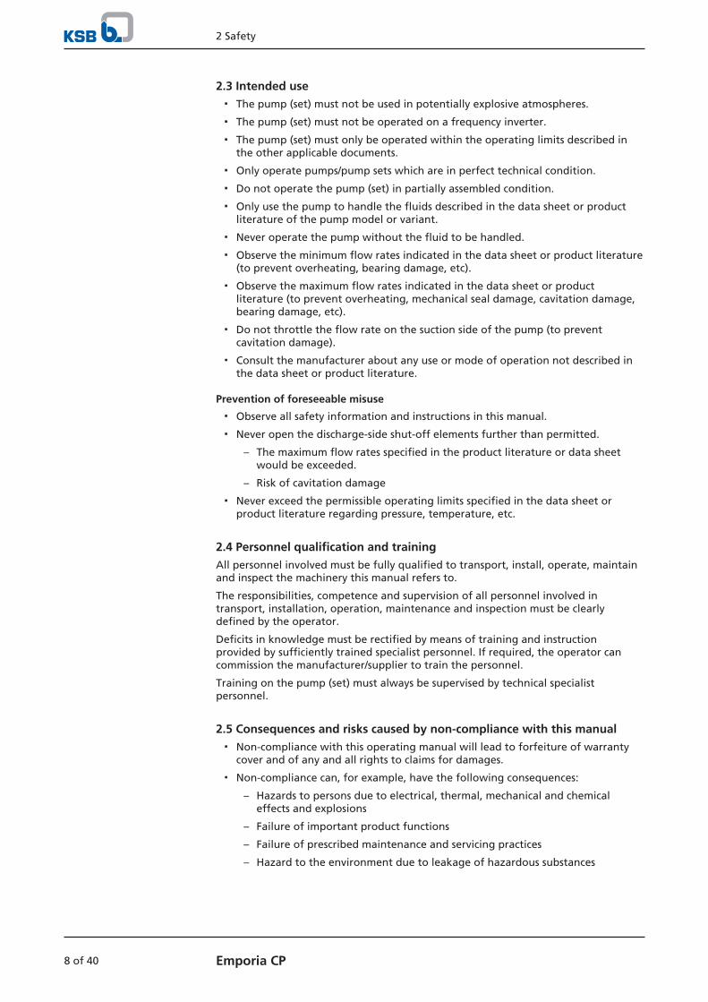
Fig. 3: Emporia CP
1 Suction nozzle 2 Discharge nozzle
Design Single-stage, non-self-priming centrifugal pump in close-coupled design with axialfluid inlet and vertical fluid outlet. The hydraulic system runs in common bearingsand is connected to the motor via a shaft.
Function The fluid enters the pump via the suction nozzle (1) and is accelerated outward bythe rotating impeller. In the flow passage of the pump casing the kinetic energy ofthe fluid is converted into pressure energy. The fluid is pumped to the dischargenozzle (2), where it leaves the pump. The shaft passage is sealed by a shaft seal. Theshaft runs in rolling element bearings.
Sealing The pump is sealed by a standardised mechanical seal. A thrower protects thebearing and the motor in the event of leakage.
4.7 Noise characteristicsSound pressure level < 70 dB(A)
4.8 Scope of supplyDepending on the model, the following items are included in the scope of supply:
▪ Pump
▪ Drive
4.9 Dimensions and weightsDimensions For dimensions refer to the outline drawings of the pump.
Weights Table 5: Weights
Size Weight [kg]
CP-101M 14
CP-101T2 14
CP-151M 22,5
CP-151T2 22,5
CP-221T2 23
CP-301T2 23,5
CP-51M 9
CP-51T2 9

4 Description of the Pump (Set)
16 of 40 Emporia CP
Size Weight [kg]
CP-81M 12,7
CP-81T2 12,7

5 Installation at Site
17 of 40Emporia CP
5 Installation at Site
5.1 Checking the site before installation
Place of installation
WARNING
Installation on mounting surfaces which are unsecured and cannot support theloadPersonal injury and damage to property!
▷ Use a concrete of compressive strength class C12/15 which meets therequirements of exposure class X0 to EN 206-1.
▷ The mounting surface must have set and must be completely horizontal andeven.
▷ Observe the weights indicated.
1. Check the structural requirements.All structural work required must have been prepared in accordance with thedimensions stated in the outline drawing/general arrangement drawing.
5.2 Installing the pump set
WARNING
Excessive temperatures due to improper installationBurns from touching hot surfaces!Damage to the pump set!
▷ Install the pump set at distance of at least 30 mm from the wall in a dry, well-ventilated room that is not at risk of flooding.
ü The place of installation has been properly prepared.
1. Install the pump set in a horizontal position.
2. Bolt the pump set to its place of installation with the feet provided for thispurpose.
5.3 Piping
5.3.1 Connecting the piping
WARNING
Impermissible loads acting on the pump nozzlesBurns from contact with fluid handled!Damage to the pump set!
▷ Do not use the pump as an anchorage point for the piping.
▷ Anchor the pipes in close proximity to the pump casing.
▷ Observe the permissible forces and moments at the pump nozzles.

5 Installation at Site
18 of 40 Emporia CP
NOTE
Installing check and shut-off elements in the system is recommended, depending onthe type of plant and pump. However, such elements must not obstruct properdrainage or hinder disassembly of the pump.
ü Suction lift lines have been laid with a rising slope, suction head lines with adownward slope towards the pump.
ü A flow stabilisation section having a length equivalent to at least twice the insidediameter of the suction flange has been provided upstream of the suction flange.
ü The nominal diameters of the pipes are equal to or greater than the nominaldiameters of the pump nozzles.
ü The pipelines have been anchored in close proximity to the pump and connectedwithout transmitting any stresses or strains.
1. Thoroughly clean, flush and blow through all vessels, pipelines and connections(especially of new installations).
2. Before installing the pump in the piping, remove the connection covers on thesuction nozzle and discharge nozzle of the pump.
3. Check that the inside of the pump is free from any foreign objects. Remove anyforeign objects.
4. Connect the pump nozzles to the piping.
CAUTION
Aggressive flushing and pickling agentsDamage to the pump!
▷ Match the cleaning operation mode and duration for flushing and picklingservice to the casing and seal materials used.
5.3.2 Permissible forces and moments at the pump nozzles
No piping-induced forces and moments (from warped pipelines or thermalexpansion, for example) must act on the pump.
5.4 Electrical connection
DANGER
Electrical connection work by unqualified personnelDanger of death from electric shock!
▷ Always have the electrical connections installed by a trained and qualifiedelectrician.
▷ Observe regulations IEC 60364.
WARNING
Incorrect connection to the mainsDamage to the mains network, short circuit!
▷ Observe the technical specifications of the local energy supply companies.

5 Installation at Site
19 of 40Emporia CP
CAUTION
Small parts in the motor spaceDamage to the pump set!
▷ Never drop small parts into the motor space.
▷ After the electrical connection work on the the pump set has been completed,check that no small parts have fallen into the motor space. If they have, removethem.
1. Check the available mains voltage against the data on the motor name plate.
2. Select an appropriate start-up method.
NOTE
A motor protection device is recommended.
Pump sets, single-phase
Fig. 4: Circuit diagram of single-phase pump sets
Pump sets, three-phase
Fig. 5: Circuit diagram of three-phase pump sets

5 Installation at Site
20 of 40 Emporia CP
5.5 Checking the direction of rotation
WARNING
Temperature increase caused by rotating partsRisk of injuries! Damage to the pump set!
▷ Never check the direction of rotation by starting up the unfilled pump set.
WARNING
Hands inside the pump casingRisk of injuries, damage to the pump!
▷ Always disconnect the pump set from the power supply and secure it againstunintentional start-up before inserting your hands or other objects into thepump.
CAUTION
Drive and pump running in the wrong direction of rotationDamage to the pump!
▷ Refer to the arrow indicating the direction of rotation on the pump.
▷ Check the direction of rotation. If required, check the electrical connection andcorrect the direction of rotation.
The correct direction of rotation of motor and pump is clockwise (seen from the driveend).
1. Start the motor and stop it again immediately to determine the motor'sdirection of rotation.
2. Check the direction of rotation. The motor's direction of rotation must match the arrow indicating the directionof rotation on the pump.
3. If the motor is running in the wrong direction of rotation, check the electricalconnection of the motor and the control system, if applicable.

6 Commissioning/Start-up/Shutdown
21 of 40Emporia CP
6 Commissioning/Start-up/Shutdown
6.1 Commissioning/Start-up
6.1.1 Prerequisites for commissioning/start-up
Before commissioning/starting up the pump set, make sure that the followingconditions are met:
▪ The pump set has been properly connected to the power supply and is equippedwith all protection devices.
▪ The pump has been primed with the fluid to be handled. The pump has beenvented.
▪ The direction of rotation has been checked.
▪ After prolonged shutdown of the pump (set), the activities required for returningthe equipment to service have been carried out. (ð Section 6.4, Page 25)
6.1.2 Priming and venting the pump
CAUTION
Increased wear due to dry runningDamage to the pump set!
▷ Never operate the pump set without liquid fill.
▷ Never close the shut-off element in the suction line and/or supply line duringpump operation.
1. Vent the pump and suction line and prime both with the fluid to be handled.
2. Fully open the shut-off element (if any) in the suction line.
NOTE
For design-inherent reasons some unfilled volume in the hydraulic system cannot beexcluded after the pump has been primed for commissioning/start-up. However,once the motor is started up the pumping effect will immediately fill this volumewith the fluid handled.
6.1.3 Start-up
DANGER
Non-compliance with the permissible pressure and temperature limits if the pumpis operated with the suction and discharge lines closedLeakage of hot or toxic fluids!
▷ Never operate the pump with the shut-off elements in the suction line and/ordischarge line closed.
▷ Only start up the pump set with the discharge-side gate valve slightly or fullyopen.
DANGER
Excessive temperatures due to dry running or excessive gas content in the fluidhandledDamage to the pump set!
▷ Never operate the pump set without a liquid fill.
▷ Prime the pump as per operating instructions.
▷ Always operate the pump within the permissible operating range.

6 Commissioning/Start-up/Shutdown
22 of 40 Emporia CP
CAUTION
Abnormal noises, vibrations, temperatures or leakageDamage to the pump!
▷ Switch off the pump (set) immediately.
▷ Eliminate the causes before returning the pump set to service.
ü The system piping has been cleaned.
ü The pump, suction line and inlet tank, if fitted, have been vented and primedwith the fluid to be pumped.
ü The lines for priming and venting have been closed.
1. Fully open the shut-off element in the suction head/suction lift line.
2. Close or slightly open the shut-off element in the discharge line.
3. Start up the motor.
4. Immediately after the pump has reached full rotational speed, slowly open theshut-off element in the discharge line and adjust it to comply with the dutypoint.
6.1.4 Checking the shaft seal
Mechanical seal The mechanical seal only leaks slightly or invisibly (as vapour) during operation.Mechanical seals are maintenance-free.
6.1.5 Shutdown
CAUTION
Heat build-up inside the pumpDamage to the shaft seal!
▷ Depending on the type of installation, the pump set requires sufficient after-run time – with the heat source switched off – until the fluid handled hascooled down.
ü The shut-off element in the suction line is and remains open.
1. Close the shut-off element in the discharge line.
2. Switch off the motor and make sure the pump set runs down smoothly to astandstill.
NOTE
If the discharge line is equipped with a check valve, the shut-off element in thedischarge line may remain open, provided the site's requirements and regulationsare taken into account and observed.
For prolonged shutdown periods:
1. Close the shut-off element in the suction line.
CAUTION
Risk of freezing during prolonged pump shutdown periodsDamage to the pump!
▷ Drain the pump and protect it against freezing.

6 Commissioning/Start-up/Shutdown
23 of 40Emporia CP
6.2 Operating limits
DANGER
Non-compliance with operating limits for pressure, temperature, fluid handled andspeedHot fluids escaping!
▷ Comply with the operating data indicated in the data sheet.
▷ Avoid prolonged operation against a closed shut-off element.
▷ Never operate the pump at product temperatures exceeding those specified inthe data sheet or on the name plate.
6.2.1 Ambient temperature
CAUTION
Operation outside the permissible ambient temperatureDamage to the pump (set)!
▷ Observe the specified limits for permissible ambient temperatures.
Observe the following parameters and values during operation:
Table 6: Permissible ambient temperatures
Permissible ambient temperature Value
Maximum 40 °C
Minimum 1 °C
6.2.2 Frequency of starts
CAUTION
Excessive surface temperature of the motorDamage to the motor!
▷ Observe the frequency of starts specified in the motor manufacturer's productliterature.
The frequency of starts is usually determined by the maximum temperature increaseof the motor. This largely depends on the power reserves of the motor in steady-state operation and on the starting conditions (DOL, star-delta, moments of inertia,etc). If the starts are evenly spaced over the period indicated, the following limitsserve as orientation for start-up with the discharge-side gate valve slightly open:
Table 7: Frequency of starts
Motor rating [kW]
Maximum No. of start-ups[Start-ups/hour]
< 4 15
> 5 10
CAUTION
Re-starting while motor is still running downDamage to the pump (set)!
▷ Do not re-start the pump set before the pump rotor has come to a standstill.
6 Commissioning/Start-up/Shutdown
24 of 40 Emporia CP
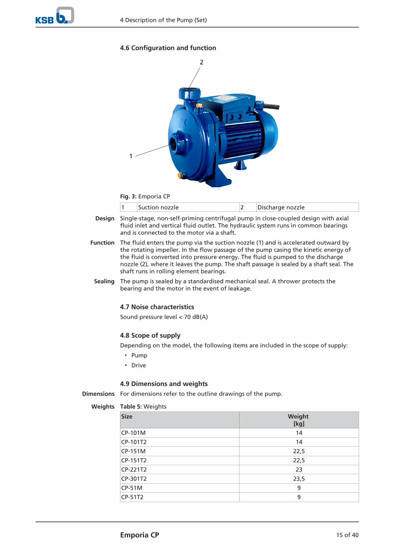
6.2.3 Maximum operating pressure
CAUTION
Permissible operating pressure exceededDamage to connections and seals!
▷ Never exceed the operating pressure specified in the data sheet.
Table 8: Maximum operating pressure
Size Maximum permissible operating pressure[bar]
CP-51 6
CP-81
CP-101
CP-151 8
CP-221
CP-301
6.2.4 Fluid handled
6.2.4.1 Fluid temperature
CAUTION
Incorrect temperature of the fluid handledDamage to the pump (set)!
▷ Do not operate the pump (set) outside the specified temperature limits.
Do not operate the pump at temperatures higher than 90 °C.
6.2.4.2 Density of the fluid handled
The pump input power changes in proportion to the density of the fluid handled.
CAUTION
Impermissibly high density of the fluid handledMotor overload!
▷ Make sure the motor has sufficient power reserves.
6.2.4.3 Abrasive fluids
When the pump handles fluids containing abrasive substances, increased wear of thehydraulic system and the shaft seal are to be expected. In this case, reduce thecommonly recommended inspection intervals.
6.3 Shutdown/storage/preservation
DANGER
Electrical connection work by unqualified personnelDanger of death from electric shock!
▷ Always have the electrical connections installed by a trained and qualifiedelectrician.
▷ Observe regulations IEC 60364.
6 Commissioning/Start-up/Shutdown
25 of 40Emporia CP
DANGER
Power supply not disconnectedDanger to life!
▷ Pull the mains plug or disconnect all electrical connections and secure againstunintentional start-up.
The pump (set) remains installed
ü Sufficient fluid is supplied for the operation check run of the pump.
1. Start up the pump (set) regularly between once a month and once every threemonths for approximately five minutes during prolonged shutdown periods. This will prevent the formation of deposits within the pump and the pumpintake area.
The pump (set) is removed from the pipe and stored
ü The pump has been properly drained and the safety instructions for dismantlingthe pump have been observed. (ð Section 7.4.1, Page 28)
1. Spray-coat the inside wall of the pump casing and, in particular, the impellerclearance areas with a preservative.
2. Spray the preservative through the suction and discharge nozzles.It is advisable to then close the pump nozzles (e.g. with plastic caps or similar).
3. Oil or grease all exposed machined parts and surfaces of the pump (withsilicone-free oil and grease, food-approved if required) to protect them againstcorrosion.Observe the additional instructions .
If the pump set is to be stored temporarily, only preserve the wetted componentsmade of low-alloy materials. Commercially available preservatives (food-approved, ifrequired) can be used for this purpose. Observe the manufacturer's instructions forapplication/removal.
Observe any additional instructions and information provided. (ð Section 3, Page 10)
6.4 Returning to serviceFor returning the equipment to service, observe the sections on commissioning/start-up (ð Section 6.1, Page 21) and the operating limits. (ð Section 6.2, Page 23)
In addition, carry out all servicing/maintenance operations before returning thepump (set) to service. (ð Section 7, Page 26)
WARNING
Failure to re-install or re-activate protective devicesRisk of personal injury from moving parts or escaping fluid!
▷ As soon as the work is complete, re-install and/or re-activate any safety-relevantand protective devices.
NOTE
If the pump has been out of service for more than one year, replace all elastomerseals.
7 Servicing/Maintenance
26 of 40 Emporia CP
7 Servicing/Maintenance
7.1 Safety regulations
NOTE
All maintenance, service and installation work can be carried out by KSB Service orauthorised workshops. For contact details please refer to the enclosed "Addresses"booklet or visit "www.ksb.com/contact" on the Internet.
The operator ensures that maintenance, inspection and installation is performed byauthorised, qualified specialist personnel who are thoroughly familiar with themanual.
DANGER
Electrical connection work by unqualified personnelDanger of death from electric shock!
▷ Always have electrical work performed by a trained and qualified electricianonly.
▷ Observe regulations IEC 60364 and HD 637 S1.
WARNING
Unqualified personnel performing work on the pump (set)Risk of injury!
▷ Always have repair and maintenance work performed by specially trained,qualified personnel.
DANGER
Insufficient preparation of work on the pump (set)Risk of injury!
▷ Properly shut down the pump set.
▷ Close the shut-off elements in suction and discharge line.
▷ Drain the pump and release the pump pressure.
▷ Close any auxiliary connections.
▷ Allow the pump set to cool down to ambient temperature.
WARNING
Unintentional starting of the pump setRisk of injury by moving components and shock currents!
▷ Ensure that the pump set cannot be started unintentionally.
▷ Always make sure the electrical connections are disconnected before carryingout work on the pump set.
WARNING
Insufficient stabilityRisk of crushing hands and feet!
▷ During assembly/dismantling, secure the pump (set)/pump parts to preventtilting or tipping over.

7 Servicing/Maintenance
27 of 40Emporia CP
A regular maintenance schedule will help avoid expensive repairs and contribute totrouble-free, reliable operation of the pump, pump set and pump parts with aminimum of servicing/maintenance expenditure and work.
7.2 Servicing/inspection
7.2.1 Supervision of operation
DANGER
Incorrectly serviced shaft sealFire hazard!
Hot fluids escaping!
Damage to the pump set!
▷ Regularly service the shaft seal.
DANGER
Excessive temperatures as a result of bearings running hot or defective bearingsealsFire hazard!
Damage to the pump set!
▷ Regularly check the rolling element bearings for running noises.
CAUTION
Increased wear due to dry runningDamage to the pump set!
▷ Never operate the pump set without liquid fill.
▷ Never close the shut-off element in the suction line and/or supply line duringpump operation.
CAUTION
Impermissibly high temperature of fluid handledDamage to the pump!
▷ Prolonged operation against a closed shut-off element is not permitted(heating up of the fluid).
▷ Observe the temperature limits in the data sheet and in the section onoperating limits. (ð Section 6.2, Page 23)
While the pump is in operation, observe and check the following:
▪ The pump must run quietly and free from vibrations at all times.
▪ Check the shaft seal. (ð Section 6.1.4, Page 22)
▪ Check the static sealing elements for leakage.
▪ Check the rolling element bearings for running noises.Vibrations, noise and an increase in current input occurring during unchangedoperating conditions indicate wear.
CAUTION
Operation outside the permissible bearing temperatureDamage to the pump!
▷ The bearing temperature of the pump (set) must never exceed 90 °C (measuredon the outside of the motor housing).
7 Servicing/Maintenance
28 of 40 Emporia CP
NOTE
After commissioning, increased temperatures may occur at grease-lubricated rollingelement bearings due to the running-in process. The final bearing temperature isonly reached after a certain period of operation (up to 48 hours depending on theconditions).
7.3 Drainage/cleaning
WARNING
Fluids, consumables and supplies which are hot and/or pose a health hazardHazard to persons and the environment!
▷ Collect and properly dispose of flushing fluid and any residues of the fluidhandled.
▷ Wear safety clothing and a protective mask if required.
▷ Observe all legal regulations on the disposal of fluids posing a health hazard.
1. Use the suction nozzle or discharge nozzle to drain the fluid handled.
2. Always flush the system if it has been used for handling noxious, explosive, hotor other hazardous fluids.Always flush and clean the pump before transporting it to the workshop.Provide a certificate of decontamination for the pump. (ð Section 12, Page 37)
7.4 Dismantling the pump set
7.4.1 General information/Safety regulations
DANGER
Insufficient preparation of work on the pump (set)Risk of injury!
▷ Properly shut down the pump set.
▷ Close the shut-off elements in suction and discharge line.
▷ Drain the pump and release the pump pressure.
▷ Close any auxiliary connections.
▷ Allow the pump set to cool down to ambient temperature.
WARNING
Unqualified personnel performing work on the pump (set)Risk of injury!
▷ Always have repair and maintenance work performed by specially trained,qualified personnel.
WARNING
Hot surfaceRisk of injury!
▷ Allow the pump set to cool down to ambient temperature.

7 Servicing/Maintenance
29 of 40Emporia CP
WARNING
Improper lifting/moving of heavy assemblies or componentsPersonal injury and damage to property!
▷ Use suitable transport devices, lifting equipment and lifting tackle to moveheavy assemblies or components.
Always observe the safety instructions and information.
For any work on the motor, observe the instructions of the relevant motormanufacturer.
For dismantling and reassembly observe the exploded views and the generalassembly drawing. (ð Section 9.1, Page 33)
In the event of damage, you can always contact our service department.
NOTE
All maintenance, service and installation work can be carried out by KSB Service orauthorised workshops. For contact details please refer to the enclosed "Addresses"booklet or visit "www.ksb.com/contact" on the Internet.
NOTE
After a prolonged period of operation the individual components may be hard topull off the shaft. If this is the case, use a brand name penetrating agent and/or - ifpossible - an appropriate puller.
7.5 Reassembling the pump set
7.5.1 General information/Safety regulations
WARNING
Improper lifting/moving of heavy assemblies or componentsPersonal injury and damage to property!
▷ Use suitable transport devices, lifting equipment and lifting tackle to moveheavy assemblies or components.
CAUTION
Improper reassemblyDamage to the pump!
▷ Reassemble the pump (set) in accordance with the general rules of soundengineering practice.
▷ Use original spare parts only.
Sequence Always re-assemble the pump in accordance with the corresponding generalassembly drawing or exploded view. (ð Section 9.1, Page 33)
Sealing elements ▪ O-rings
– Check O-rings for any damage and replace by new O-rings if required.
– Never use O-rings that have been made by cutting an O-ring cord to size andgluing the ends together.
▪ Assembly adhesives
– Avoid the use of assembly adhesives if possible.
Tightening torques For reassembly, tighten all screws and bolts as specified in this manual.(ð Section 7.6, Page 30)
7 Servicing/Maintenance
30 of 40 Emporia CP
7.6 Tightening torques
Table 9: Tightening torques for bolted/screwed connections
Position Nominal value[Nm]
Pump casing 10
Tie bolt 15
Impeller nut 10
7.7 Spare parts stock
7.7.1 Ordering spare parts
Always quote the following data when ordering replacement or spare parts:
▪ Type series
▪ Size
▪ Order number
▪ Order item number
▪ Series code
▪ Year of construction
Refer to the name plate for all data.
Also specify the following data:
▪ Part number and description
▪ Quantity of spare parts
▪ Shipping address
▪ Mode of dispatch (freight, mail, express freight, air freight)

8 Trouble-shooting
31 of 40Emporia CP
8 Trouble-shooting
WARNING
Improper work to remedy faultsRisk of injury!
▷ For any work performed to remedy faults, observe the relevant informationgiven in this operating manual and/or in the product literature provided by theaccessories manufacturer.
If problems occur that are not described in the following table, consultation with theKSB customer service is required.
A Pump delivers insufficient flow rate
B Motor is overloaded
C Leakage at the pump
D Excessive leakage at the shaft seal
E Vibrations during pump operation
F Impermissible temperature increase in the pump
Table 10: Trouble-shooting
A B C D E F Possible cause Remedy2)
✘ - - - - - ▪ Pump delivers against an excessivelyhigh pressure.
▪ Check system for impurities.
✘ - - - ✘ ✘ ▪ Pump and/or piping are notcompletely vented and/or primed.
▪ Vent and/or prime.
✘ - - - - - ▪ Supply line or impeller clogged ▪ Remove deposits in the pump and/or piping.
✘ - - - - - ▪ Formation of air pockets in thepiping
▪ Alter piping layout.
▪ Fit a vent valve.
✘ - - - - - ▪ Air intake at the shaft seal ▪ Supply external barrier fluid and/or increase itspressure.
▪ Fit new shaft seal.
✘ - - - - - ▪ Wrong direction of rotation ▪ Check the electrical connection of the motor andthe control system, if any.
✘ - - - ✘ - ▪ Wear of internal components ▪ Replace worn components by new ones.
- ✘ - - ✘ - ▪ Pump back pressure is lower thanspecified in the purchase order.
▪ Re-adjust to duty point.
- ✘ - - - - ▪ Density or viscosity of fluid handledhigher than stated in purchase order
▪ Contact KSB.
- - ✘ - - - ▪ Tie bolts/sealing element defective ▪ Replace sealing element at pump casing.
▪ Re-tighten the bolts.
- - - ✘ - - ▪ Worn shaft seal ▪ Fit new shaft seal.
- - - ✘ - - ▪ Dismantle to find out. ▪ Remedy.
▪ Fit new shaft seal, if required.
- - - ✘ ✘ - ▪ Pump is warped or sympatheticvibrations in the piping.
▪ Check pipeline connections and secure fixing ofpump; if required, reduce the distances betweenthe pipe clamps.
▪ Fix the pipelines using anti-vibration material.
✘ ✘ - - - - ▪ Motor is running on 2 phases only. ▪ Replace the defective fuse.
▪ Check the electrical cable connections.
- - - - ✘ - ▪ Rotor out of balance ▪ Clean the impeller.
- - - - ✘ - ▪ Defective bearing(s) ▪ Replace.
2) Pump pressure must be released before attempting to remedy faults on parts which are subjected to pressure.

8 Trouble-shooting
32 of 40 Emporia CP
A B C D E F Possible cause Remedy2)
✘ ✘ - - - ✘ ▪ Thermal motor protection device hastripped.
▪ Verify that mains voltage matches the voltageindicated on the name plate.
▪ Ensure that the motor ventilation openings areclear.
✘ - - - - - ▪ Excessive pressure loss in the piping ▪ Check whether piping diameter is too small orpiping is clogged.
9 Related Documents
33 of 40Emporia CP
9 Related Documents
9.1 Exploded view and list of components
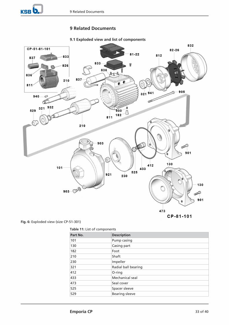
Fig. 6: Exploded view (size CP-51-301)
Table 11: List of components
Part No. Description
101 Pump casing
130 Casing part
182 Foot
210 Shaft
230 Impeller
321 Radial ball bearing
412 O-ring
433 Mechanical seal
473 Seal cover
525 Spacer sleeve
529 Bearing sleeve

9 Related Documents
34 of 40 Emporia CP
Part No. Description
81-22 Terminal box cover
82-26 Fan
811 Motor housing
812 Motor housing cover
826 Cable gland
832 Fan hood
833 Terminal box
836 Terminal strip
837 Capacitor
900 Screw
901 Hexagon head bolt
903 Screw plug
905 Tie bolt
921 Shaft nut
932 Circlip
940 Key
941 Woodruff key

10 EU Declaration of Conformity
35 of 40Emporia CP
10 EU Declaration of Conformity
Manufacturer: KSB SE & Co. KGaAJohann-Klein-Straße 9
67227 Frankenthal (Germany)
The manufacturer herewith declares that the product:
Emporia CP, Emporia MB, Emporia PD (T..., 3~)Series code range: 2016w39 - 2018w52
▪ is in conformity with the provisions of the following Directives as amended from time to time:
– Pump (set): Machinery Directive 2006/42/EC
The manufacturer also declares that
▪ the following harmonised international standards have been applied:
– ISO 12100
– EN 809
– EN 60034-1, EN 60034-5/A1
Person authorised to compile the technical file:
Dr. Lutz UrbanHead of Product Development Standardised Water PumpsKSB SE & Co. KGaAJohann-Klein-Straße 9 67227 Frankenthal (Germany)
The EU Declaration of Conformity was issued in/on:
Frankenthal, 1 February 2018
Thomas Heng
Head of Product Development Series Pumps
KSB SE & Co. KGaAJohann-Klein-Straße 9
67227 Frankenthal
11 EU Declaration of Conformity
36 of 40 Emporia CP
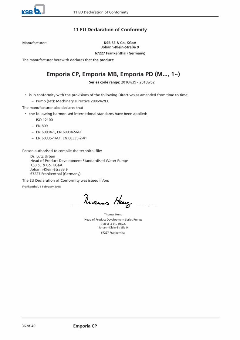
11 EU Declaration of Conformity
Manufacturer: KSB SE & Co. KGaAJohann-Klein-Straße 9
67227 Frankenthal (Germany)
The manufacturer herewith declares that the product:
Emporia CP, Emporia MB, Emporia PD (M..., 1~)Series code range: 2016w39 - 2018w52
▪ is in conformity with the provisions of the following Directives as amended from time to time:
– Pump (set): Machinery Directive 2006/42/EC
The manufacturer also declares that
▪ the following harmonised international standards have been applied:
– ISO 12100
– EN 809
– EN 60034-1, EN 60034-5/A1
– EN 60335-1/A1, EN 60335-2-41
Person authorised to compile the technical file:
Dr. Lutz UrbanHead of Product Development Standardised Water PumpsKSB SE & Co. KGaAJohann-Klein-Straße 9 67227 Frankenthal (Germany)
The EU Declaration of Conformity was issued in/on:
Frankenthal, 1 February 2018
Thomas Heng
Head of Product Development Series Pumps
KSB SE & Co. KGaAJohann-Klein-Straße 9
67227 Frankenthal
12 Certificate of Decontamination
37 of 40Emporia CP
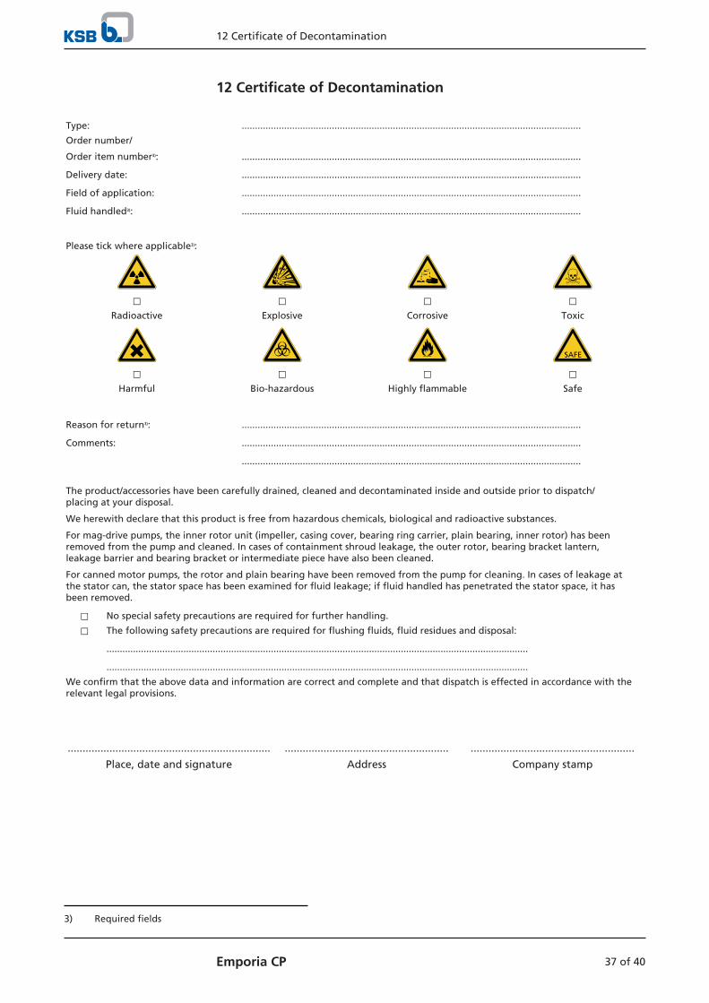
12 Certificate of Decontamination
Type: ................................................................................................................................
Order number/
Order item number3): ................................................................................................................................
Delivery date: ................................................................................................................................
Field of application: ................................................................................................................................
Fluid handled3): ................................................................................................................................
Please tick where applicable3):
⃞ ⃞ ⃞ ⃞Radioactive Explosive Corrosive Toxic
⃞ ⃞ ⃞ ⃞Harmful Bio-hazardous Highly flammable Safe
Reason for return3): ................................................................................................................................
Comments: ................................................................................................................................
................................................................................................................................
The product/accessories have been carefully drained, cleaned and decontaminated inside and outside prior to dispatch/placing at your disposal.
We herewith declare that this product is free from hazardous chemicals, biological and radioactive substances.
For mag-drive pumps, the inner rotor unit (impeller, casing cover, bearing ring carrier, plain bearing, inner rotor) has beenremoved from the pump and cleaned. In cases of containment shroud leakage, the outer rotor, bearing bracket lantern,leakage barrier and bearing bracket or intermediate piece have also been cleaned.
For canned motor pumps, the rotor and plain bearing have been removed from the pump for cleaning. In cases of leakage atthe stator can, the stator space has been examined for fluid leakage; if fluid handled has penetrated the stator space, it hasbeen removed.
⃞ No special safety precautions are required for further handling.
⃞ The following safety precautions are required for flushing fluids, fluid residues and disposal:
...............................................................................................................................................................
...............................................................................................................................................................
We confirm that the above data and information are correct and complete and that dispatch is effected in accordance with therelevant legal provisions.
.................................................................... ....................................................... .......................................................
Place, date and signature Address Company stamp
3) Required fields

Index
38 of 40 Emporia CP
Index
AAbrasive fluids 24
Applications 8
Assembly 29
BBearings 14
CCertificate of decontamination 37
Commissioning 21
DDesign 14
Designation 13
Direction of rotation 20
Dismantling 29
Disposal 12
Drive 14
EEvent of damage
Ordering spare parts 30
FFaults 31Fluid handled
Density 24
Frequency of starts 23
IImpeller type 14
Installation 17
Installation at site 17
Intended use 8
MMechanical seal 22
Misuse 8
NName plate 14
OOperating limits 23
Operating pressure 24
Order number 6
Other applicable documents 6
PPartly completed machinery 6
Permissible forces at the pump nozzles 18
Piping 18
Preservation 25
Product description 13
RReassembly 29
Return to supplier 11
Returning to service 25
SSafety 7
Safety awareness 9
Scope of supply 15
Shaft seal 14
Shutdown 25Spare part
Ordering spare parts 30
Start-up 22
Storage 11, 25
TTightening torques 30
Transport 10


KSB SE & Co. KGaA
Johann-Klein-Straße 9 • 67227 Frankenthal (Germany)
Tel. +49 6233 86-0
www.ksb.com
5132
.83/
02-E
N


![8117.1 02 EN - shop.ksb.com · Check Valves and Strainers. Nozzle Check Valves to DIN/EN 5. BOA-RFV. Pressure/temperature ratings. Permissible operating pressures [bar] (to EN 12266-1)](https://img.dokumen.tips/doc/110x75/5dd0891dd6be591ccb61764a/81171-02-en-shopksbcom-check-valves-and-strainers-nozzle-check-valves-to-dinen.jpg)