Embed Size (px)
Citation preview

The M-FLEX LNG Carrier Design – Creating Value in Three Parts of the LNG Chain
Authors Nicholas Jones Manager Concept Development Dr Trym Tveitnes Chief Technical Officer

1. Introduction
In March 2006 FLEX LNG entered the LNG shipping business by placing an order with Samsung Heavy Industries (SHI) for the construction of two new LNGC’s. This LNGC order was unique among others as it was placed for a new type of LNGC design known as the M-FLEX. The first M-FLEX LNGC is expected to be delivered in late 2010 with the second ship expected to be delivered in early 2011. Late last year FLEX LNG declared an option for a third M-FLEX vessel to be delivered in 2011. The M-FLEX design represents a significant change away from the well established traditional LNG shipping designs. Such a dramatic design change in LNG shipping has not been seen by the industry for many years. With the announcement of the M-FLEX LNGC order with Samsung, FLEX LNG also introduced to the LNG market the idea of the flexible LNG shipping concept. The LNG industry was quick to appreciate that the M-FLEX design was innovative in many ways. The M-FLEX offers the industry a ship with tangible design flexibility and real choices regarding its trading application an outcome inherit to its new design. The novel M-FLEX design has reversed the conventional LNGC "bigger and bigger" evolutionary trend and has marked the return of the Self Supporting Prismatic Shape IMO Type B (SPB) cargo tank again in the LNG shipping business. The selection of this tank technology in preference to traditional tank designs allows the M-FLEX to operate safely with partial LNG cargos whilst still offering a flat deck leading to a significant expansion in the vessels operational flexibility. FLEX LNG with its M-FLEX design is able to offer the industry a level of flexibility in LNG transportation that up till now has not been available and which the market is starting to demand. The M-FLEX LNGC design can be traded as an efficient LNGC, a re-gasification vessel (trading as a conventional re-gasification ship or LNG re-gasification facility) or an LNG production facility. For the first time FLEX LNG with the M-FLEX design can offer the market a floating solution for each component of the LNG supply chain from production to the shipping and finally to re-gasification, with each component being based on a sole tank technology. This paper will explore the design evolution of the M-FLEX LNGC in some detail, providing a discussion on the commercial background that influenced how the M-FLEX design was conceptualised and describing the major developments that have taken place to date.
2. The Commercial Background for the M-FLEX Design
The trend in the LNG industry in recent times has been to increase unit size in an attempt to reduce unit cost based on the economies of scale principle which has been successfully proven in other industries. This principle has been applied to the liquefaction processing plant, the systems which produce the cargo for the LNGC ships to transport to market for some time. Over the last three decades there has been significant work and development into increasing the train size of LNG production plants with the aim of improving project economics and also having an additional benefit of reducing LNG plant layouts for a given capacity which has environmental impact advantages. As an example of this trend from 1975 to 2005 the size of an LNG train that could be produced had quadrupled in size. However, over the same period of time the size of LNGC’s remained virtually unchanged in the 125,000 - 150,000 m3 range. This can be contributed to a number of factors namely: ship builder’s unwillingness to change established designs because of the time consuming and expensive nature of the approval process; potentially the revision of construction procedures and possibly training of the work force and also the fact that existing LNG import and export terminals are limited to accept a certain range of LNGC sizes as a consequence of been designed, more often than not, many years ago based on the largest assumed LNGC expected over the design life of the facility.
Jones & Tveitnes

It is interesting to note that this 125 -150,000 m3 LNGC range corresponds to the size required by the dominant pacific market which still accounts for approximately 50% of long term LNG shipping fleet charters. This LNG market constitutes the main LNG shipping routes with most LNG cargoes leading to Japan from various countries within the South East Asia region. This eventually resulted in the most common LNGC size range for this region being labelled the "Japan-max" design. When the first orders were placed for the Qatar fleet, this heralded a new era in LNG shipping. What emerged were two brand new LNGC sizes, significantly larger than the Japan-max design namely the Q-Flex and the Q-Max at approximately 215,000 m3 and 265,000 m3 storage capacity respectively. For many in the industry it looked that these larger ships were the future of the long-haul LNG trade and were to dominate future LNGC shipping orders. Approximately around the same time in the Mediterranean, the so-called "Med-max" designs of approximately 75,000 m3 were introduced. These sized ships were ideal for the short sea trade and also maximised the possibilities of the existing ports infrastructure. This market had been well serviced mainly by a fleet comprising of ships in the 30,000 to 40,000 m3 range. Historically within other shipping sectors, the introduction of larger and larger ships had also given rise for a demand for mid-sized vessels. This applies very well for the shipping container market. The demand for such mid size vessels in the container shipping market was mainly due to a need for greater flexibility within the shipping fleet. FLEX LNG studied and analysed the LNG shipping market extensively and discovered a niche area - a strong future industry need for a mid-sized Panamax ship that could transit the Panama Canal for short and small trades. It seemed as if what had occurred within the container shipping market was repeating itself in the LNG shipping market. One of the economic drivers for such a vessel in the LNG shipping fleet is that a Panamax size LNGC can deliver LNG from Trinidad to Japan more economically than a Japan-max ship sailing around the Cape of Good Hope or the Suez Canal. Figure 1: below shows that there is no LNGC currently or on order within the 90,000 m3 to 120,000 m3 range and also compares the average age of vessels in various range sizes.
0
50
100
150
200
250
300
350
up to5'm3
5 -20'cbm
20 -60'cbm
60 -90'cbm
90 -120'cbm
above120' cbm
Nu
mbe
r o
f ve
sse
ls
0
5
10
15
20
25
30
35
40
Ye
ars
Existing vessels and order book Average Age
Figure 1 Shows the lack of LNGC in the existing and currently ordered fleet within the 90 to
120,000 m3 range. One other key trend in the LNG trade, prior to the M-FLEX design being announced was an increasing lack of flexibility in the LNGC shipping sector. Previously LNGC’s were designed and constructed with the intent for a sole trading purpose without taking into consideration other future trading applications. Recently a new market has been established in the LNG shipping industry namely the conversion of LNG ships into FSRU’s and as a consequence of this precedent many
Jones & Tveitnes

studies are now looking at the feasibility of converting and modifying existing LNGC into LNG FPSO’s albeit with potential operational limitations. Furthermore generally speaking current liquefaction plants produce LNG at a virtually fixed rate, with very little ability for variable production as the consumer demands ie "turn up or down" production when demand warrants. However the demand for LNG in many regions is very seasonal and can vary considerably. So there often exists a mis-match between supply (LNG production) and demand and this gap is met by a combination of excess storage at the liquefaction and re-gasification sides of the supply chain and LNGC slow-steaming (or lay-up). This situation has been exacerbated in recent years with the move away from Moss-type ships to membrane vessels. Moss ships generally offer a greater range of options in terms of part-cargoes due to the functionality of the tank design, but at a significant economic penalty if a Suez Canal transit is involved. In response to the issues raised above the M-FLEX design offers a flat upper deck for the installation of topside equipment (either liquefaction or re-gasification) and a truly flexible route planning and part delivery (or part cargo) capability all made possible by adopting the "SPB" tank design, which SHI is able to offer under Licence from the Patent-holders, Ishikawa Harima Heavy Industries, Japan (IHI). Figure 2 below shows a GA of the M-FLEX and a representation of how it will look.
Jones & Tveitnes

Figure 2 A GA of the M-FLEX and a representation what M-FLEX will look like
When the M-FLEX design was unveiled to a curious industry, it was also clear that the selection of Dual-Fuel Diesel-Electric propulsion also offered significant opportunities in trade balancing by offering a much lower fuel cost compared to the steam-powered ships that had dominated the industry in the past. This and other technical aspects of the M-FLEX design will be discussed in further detail below.
3. The Main Technical Aspects of the M-FLEX Design
3.1 Propulsion
When the first LNG carriers were built in the 1960’s, some 50% of the world’s merchant ships were steam-propelled. It was logical to adopt steam propulsion for LNGC’s, as the inevitable boil-off gas from the cryogenic cargo could simply be burned in a steam boiler and used to power the ship. The design speed of the early ships was in part chosen to balance the power requirement with the quantity of boil-off anticipated. The dramatic fuel price increases of the 1970’s saw the end of steam power for merchant ships, except for LNG carriers. The relatively steady growth of the LNG fleet during the 1980’s and 1990’s did not pose any problems for the few remaining suppliers of marine steam equipment and the training of specialist marine steam engineers. But by the turn of the century, the upsurge in the LNG trade put extreme pressure on both turbine makers and the industry’s ability to train steam engineers. Coupled with this was the fact that steam turbines have relatively low efficiency and with emergence of larger new LNGC designs this prompted a review into investigating the feasibility of alternative propulsion systems. If the LNG shipping industry was to change its propulsion to diesel, the industry had to develop ways to manage the cargo boil-off. Two solutions evolved - the first used an adapted medium-speed 4-stroke engine developed by Wartsila that was capable of burning either fuel oil fuel boil-off gas. The alternative solution used 2-stroke fuel oil engines in combination with using a separate re-liquefaction plant to manage the boil off by converting it into LNG and then returning it back to the cargo tanks. The Wartsila Duel Fuel engines were selected for the M-FLEX LNGC design. This gives the design a significant trading advantage over a steam-ship, especially where re-positioning voyages are required. The Dual-Fuel Diesel-Electric (DF/DE) system adopted for the M-FLEX design has several other advantages that further improve the ship’s flexibility. Most notable is the fact that the multi-engine layout offers a range of "economic speed" options with 2, 3 or 4 engines running. When a ship is not dedicated to a specific trade, this fuel economy flexibility is of great potential value to Charterers. LNG carriers are characterised by a high electrical load in port especially during full-rate cargo discharge and the DF/DE design offers the lowest possible installed power because the machinery duty is interchanged between propulsion and in-port loads. Multi-engine layouts also offer the opportunity to carry out routine maintenance in-port (subject to approval) or at sea. This means it is potentially easier to keep the ship in service continuously between dry-docking periods .
3.2 SPB Cargo Containment Technology
Although the SPB cargo tank design derives directly from the very first tank design used in the LNG industry, very few ships have ever been built to this design, mainly due to reasons of cost competitiveness with established tank designs which up until recently can be associated with a lack of alternative builders to the patent-holders IHI.
Jones & Tveitnes

Of the entire LNG shipping fleet SPB LNG ships account for a very small percentage. The most notable SPB LNG ships that have been built to date are the Polar Eagle and Arctic Sun each of 87,500 m3 capacity ordered in 1990 from IHI and delivered in 1993. These ships were put into service between Kenai Alaska and Yokohama Japan a harsh environmental shipping route. However the SPB tank design has also been applied to a number of ethylene ships such as the Kayoh Maru and is often selected as the preferred containment system for LPG FSO’s & FPSO’s including but not limited to the Escavros FSO & Sanha LPG FPSO’s operating offshore West Africa. However the vast majority of existing LNG ships on order currently are using or will use once in service tank designs that were developed in the 1960’s and 1970’s namely the Moss-Rosenberg (sphere) containment system and the membrane type containment system designed by Technigaz and Gas Transport independently and which have since merged together operating as GTT. In contrast the SPB tank technology as used in Polar Eagle and Arctic Sun ships was designed in the early to mid 1980’s. All tank technologies have advantages and disadvantages however the selection of the cargo containment system is governed on the expected trading application and the vessels route service which will be discussed below. Until the recent upsurge in the LNG business, approximately equal numbers of ships were built with spherical and membrane tanks. The majority of this upsurge in the LNG industry was visible in the demand of new LNG projects in the Atlantic region. These new ships for the projects were required to pass through the Suez Canal where spherical ships face a significant cost penalty in comparison to membrane ships with the same storage volume. This was the main driving factor why membrane ships became the design of choice and why membrane type ships now account for approximately more than 85% of the new build LNG shipping market. One of the key advantages of the membrane concept is that the cargo tanks can be designed to suit the length and beam of the ship, whereas the potential for geometric variation of a sphere is relatively restricted. However, membrane tanks face restrictions with respect to partial filling in comparison to the moss containment system. In the traditional LNG shipping business due there being no commercial need for LNG ships with a partial cargo capabilities in most services (ie full cargoes always being envisaged) the ability for partial filling is not a critical in the selection of a tank containment system. However for floating LNG production and LNG re-gasification sloshing resistant tank designs are required along with a flat uncongested deck space for production and re-gasification systems In recognition of the limitations of the dominant containment systems for applications outside that of traditional LNG shipping and aiming for the specialised offshore market, SHI negotiated to build SPB tanks under licence from IHI, and this containment system has become the basis of the M-FLEXdesign. Figure 3 shows a representation of the M-FLEX SPB tank technology.
Figure 3 A representation of the SPB tank containments system for the M-FLEX LNGC
Jones & Tveitnes

SHI’s adaptation of the SPB design sees the original Aluminium alloy replaced by Stainless Steel. This fact, combined with the relatively narrow beam of the ship, means that the cargo tanks do not suffer "sloshing" problems even without a centre-line bulkhead. However, it is anticipated that a CL-bulkhead will be required for other SPB tank geometries. The major difference between the Moss sphere and the SPB tanks is that the dimensions of the IHI tank system can be selected to suit the dimensions of the ship. In this respect, the SPB system has the flexibility of the membrane designs. However, SPB tanks can readily be adapted for the full range of partial filling which in turn offers the prospect of flexible route planning for the ship. The other advantages of using the SPB design are the ability to inspect and maintain the inner hull easily as there is ample access all around the cargo tanks. The cargo tank insulation is normally made from double-layer polyurethane fixed to the tank surfaces which provide channels for nitrogen purging to maintain dry & inert conditions in the insulation. The specification of the insulation system can be adapted to reduce the boil-off rate to the level required.
3.2 Other Features and Applications of the M-FLEX Design
As a result of adopting the SPB tank system, the M-FLEX has a flat uncongested deck space which offers the designers the flexibility to configure the ship for different trading applications with relative ease from the early design phases or for future conversion type projects. This fact, combined with the energy-efficient DF/DE propulsion, means the ship can be fitted with cargo re-liquefaction if the charterer requires maximum cargo out-turn and maximum heavy fuel oil consumption. The M-FLEX can be supplied as an efficient LNGC or can be re-configured for Offshore LNG Operations such as LNG Production or LNG Re-gasification. Figure 4 graphically shows the different trading applications of the M-FLEX concept.
Figure 4 Illustrates the different applications and target markets of the M-FLEX concept To enable offshore LNG applications the M-FLEX has an area forward reserved for a disconnectable Single Point Mooring (SPM) internal turret type system. Similar systems have been used extensively by the offshore industry for FPSO projects for many years and are well proven. The provision for a forward turret was originally conceived to enable the M-FLEX to be re-configured as a typical "re-gasification" ship. Figure 5 shows a representation of the M-FLEX configured as a re-gasification ship & as a FSRU.
Figure 5 The M-FLEX graphical represented as a Re-gasification ship and as a FSRU
Jones & Tveitnes
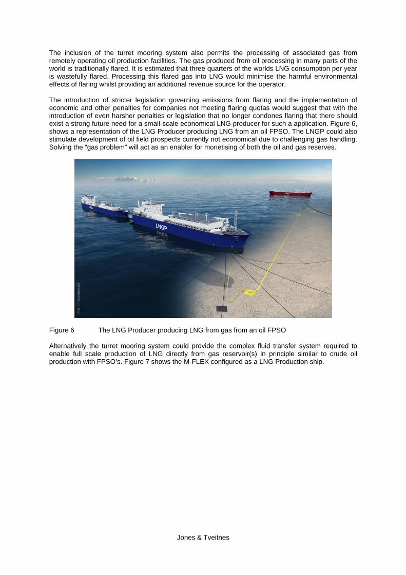
The inclusion of the turret mooring system also permits the processing of associated gas from remotely operating oil production facilities. The gas produced from oil processing in many parts of the world is traditionally flared. It is estimated that three quarters of the worlds LNG consumption per year is wastefully flared. Processing this flared gas into LNG would minimise the harmful environmental effects of flaring whilst providing an additional revenue source for the operator. The introduction of stricter legislation governing emissions from flaring and the implementation of economic and other penalties for companies not meeting flaring quotas would suggest that with the introduction of even harsher penalties or legislation that no longer condones flaring that there should exist a strong future need for a small-scale economical LNG producer for such a application. Figure 6, shows a representation of the LNG Producer producing LNG from an oil FPSO. The LNGP could also stimulate development of oil field prospects currently not economical due to challenging gas handling. Solving the “gas problem” will act as an enabler for monetising of both the oil and gas reserves.
Figure 6 The LNG Producer producing LNG from gas from an oil FPSO Alternatively the turret mooring system could provide the complex fluid transfer system required to enable full scale production of LNG directly from gas reservoir(s) in principle similar to crude oil production with FPSO’s. Figure 7 shows the M-FLEX configured as a LNG Production ship.
Jones & Tveitnes

Figure 7 The LNG Producer producing LNG directly from a gas field In addition to the features above, the M-FLEX design features the latest ship technology to ensure safe and efficient operations, such as a state-of-the-art IAS system, compatibility with the maximum number of existing LNG import and export terminals, integrated Emergency Shutdown System (ESD) systems that can be linked to most shore systems and efficient mooring equipment specifically adapted to use synthetic mooring lines. Table 1 below provides a comparison between the hull particulars of the M-FLEX design configured as LNGC and as a LNG P.
PARTICULARS M-FLEX LNGC M-FLEX LNGP Length over all (m) 290 249 Length b.p. (m) 279 238 Breadth (m) 32.24 42.0 Depth (m) 22.5 26.8 Summer Loaded Draft (m) 11.1 11.0 Scantling Draft (m) 12.0 12.0 Tank Type SPB SPB Cargo Capacity (100% volume, -163, atm) m3
90,000 90,000
Cargo Tank Arrangement 4 centre tanks (without CL BHD)
4 centre tanks (with CL BHD)
Dead weight at summer loaded draught
50,000 MT 50,000 MT
Displacement (MT) 84,100 (approx) 87,300 (approx) Permanent Fresh Water Ballast 6000 (approx) None Service Speed with 15% sea margin at design draught (knots)
18.5 12
D.F.O.C (ton/day) 104.1 104.1 B.O.R per day (% of cargo tank volume)
0.18 0.18
Ship Turret Mooring System No Single Point Mooring Internal Turret located forward
Table 1 A comparison between the hull particulars of the M-FLEX LNGC and the M-FLEX
LNGP
Jones & Tveitnes

4 Development of the M-FLEX Design – Focussing on LNG Production Applications
The design development of the M-FLEX concept has continued at a rapid pace since the original contract was first signed. Market interest into the M-FLEX concept has warranted the exercising of at least one ship option as specified in the initial contract. When Flex LNG initially approached the market and offered the industry a choice of a flexible LNGC design that could be supplied as either a straightforward, efficient ship, or a floating re-gasification vessel or an LNG production unit it soon became apparent that there was an abnormal large industry interest for the first M-FLEX vessels to be supplied with LNG producing capabilities. Consequently FLEX LNG has focussed its design efforts to date towards configuring the M-FLEX for LNG production. Figure 8 shows a GA of the LNGP and a representation of how the LNG Producer will look like.
Figure 8 A GA of the LNGP and a representation of how it will look like
The reason for the market demand for a ship capable for LNG production is quite logical and understandable upon some study. Many of the LNG liquefaction terminal projects currently in sanction are running late, are suffering serious cost-over runs or are experiencing significant early problems. The culmination of these issues has resulted in a forecast of a shortfall of LNG production to supply the market commencing from 2011 onwards. At the same time the efficient shipbuilding industry is delivering LNG ships into a market on time and on budget, but it is a market with a shortage of cargo because the LNG production projects will be coming on stream later than forecasted. Figure 9 Shows the forecasted demand for LNG up until 2025 illustrating that project coming on late could have a significant impact of the supply and demand balance.
Jones & Tveitnes

Figure 9 The world wide demand of LNG up until 2025
So a simple, practical and flexible liquefaction ship is a very welcome addition to the market to close this gap between production capacity and shipping capacity. However the current interest in the LNG Producer concept goes beyond the markets current shortage of LNG cargo. The ability to place a ship over a relative small remote gas field to produce LNG economically for a limited period of say 5 to 10 years opens up the market possibilities dramatically. After a field has come to the end of its life it is possible to take the LNG Producer and commence production from another field with only small modifications required. The potential advantages of floating LNG liquefaction plants have been discussed at length in the past, so it is not intended to repeat these arguments here. It is important to note that the key to making such a concept feasible involves a design based on flat decks and the ability to operate with part-filled cargo tanks. The proven SPB containment system is the enabling technology that offers these flexible operation characteristics. Figure 10 shows how the SPB tank designs compare between the M-FLEX and the SPB.
Figure 10 A comparison between the SPB tank design of the M_FLEX and the LNGP
Jones & Tveitnes

There are numerous small reserves of proven "stranded gas" around the world, often discovered some time ago when larger oil and gas companies were prospecting for oil. In the past when a field was discovered and it was proved to contain only small amounts of oil but larger amounts of gas it was often overlooked and sometimes the permit rights released as companies believed it would not prove an economic field development even with the emergence of new enabling technologies. Figure 11 shows small to medium gas fields that are potential candidates for offshore LNG production. :
Figure 11 The number of known gas fields categorised according to size
In today’s world with the development of an economically-viable floating LNG production plant in combination with increasing gas prices and on the horizon the establishment of a LNG spot cargo market these factors transform these fields from overlooked resources to potentially very profitable assets. Also many of these proven stranded gas reserves permit licences are held by small independent companies that like FLEX LNG are dynamic and agile and can react quickly to developing market needs. In some cases, such as when the distance from the production field to market is above certain threshold, it is beneficial to scale the size of the M-FLEX design upwards so it can have the operational buffer storage capacity to be able to offload to conventional sized LNGC offtake vessels that are operating in the market such as the "Japan-max" size range. The LNG production equipment of the LNG Producer involves two general parts a typical pre-treatment system and a liquefaction system. The pre-treatment system removes acid gas and water from the feed gas in effect drying the gas to a specified dew point temperature. A double nitrogen expansion system based on the Brayton cycle has been selected as the liquefaction plant technology. Sea water is used to cool the nitrogen. The LNGP selected liquefaction production capacity is 1 Million metric tonnes of LNG per year composed of two separate trains of equal size. However the LNG production capacity can be increased if desired. There is also provision in the design of the LNG Producer for additional field specific inlet facilities and expanded feed gas pre-treatment, Figure 12 below shows an overview of the different parts of the processing system.
Jones & Tveitnes

Figure 12 Overview of Gas Condition and Liquefaction Systems
The Brayton cycle is well known and is widely used in Peak Shaving LNG plants ashore where it is important to have the ability to stop and start production quickly and easily. Brayton cycle plants offers design simplicity, ease of operation and control, a level of immunity from process upsets (especially in relation to vessel motions), single refrigerant cycle operating in a single phase, relatively low equipment count with a small footprint and higher inherent safety in comparison to alternative technologies mainly because of a significantly reduced hydrocarbon inventory. The first LNGC boil-off re-liquefaction plants entered service in late 2007 and these units use the same nitrogen expander liquefaction principle. The installation of such systems on large LNGC has already started to prove the design of this liquefaction technology in a marine environment. The extra power required for the operation of the LNG treatment & liquefaction plant will be provided by gas turbines, with the ability to operate on boil off gas, feed gas, produced condensate or diesel oil when the process system is unavailable. Depending on site specific conditions there could be a need for some form of heading control of the LNGP. Heading control is expected to be achieved by using aft mounted azimuthing thrusters sized to provide adequate heading control to enhance the availability for offloading from the LNGP and also to minimize roll motions when production mode LNG produced will be offloaded to LNGC’s via the LNG Producers advanced integrated offloading system. There are two offloading concepts that are being proposed: a side by side concept for use in benign metocean locations and a tandem offloading system to be used in harsher metocean locations. For the side by side case the LNGC is to be moored to the LNG Producer using quick release hooks permanently installed on the LNGP and pneumatic fenders that are to be stored and deployed by davits located on the LNG Producer. Offshore marine loading arms or potentially cryogenic hose could be used to facilitate the transfer of LNG between the LNG Producer and the LNGC. Proven marine loading arms are the transfer equipment of choice at this point in time as there are no proven flexible cryogenic hoses available for continuous routine use in the demanding dynamic conditions that exist offshore. Provision has been made at the aft of the LNG Producer for the installation of a tandem offloading system, as shown in the GA drawings above. A number of tandem offloading systems are being studied for this purpose. The LNG Producer design received approval in principle from DNV in August 2007. Table 2 provides a summary of the LNGP main features.
Jones & Tveitnes

Jones & Tveitnes
LNG PRODUCER MAIN FEATURES Propulsion Single Shaft Propeller and/or Azimuthing
Thrusters Heading Control (if required) Aft mounted Azimuthing Thrusters Power Generation Choice between DFDE and/or Gas Turbines Offloading System Offshore Marine Loading Arms and/or Tandem
Offloading System Ship Mooring System Single Point Mooring Internal Dis-connectable
Type Turret Ship to Ship Mooring System Side by Side using dedicated quick release hooks
and pneumatic type floating fenders Liquefaction Process Dual Nitrogen Expansion
Table 2 Summary of the LNGP main features
6. Conclusion This paper has given an overview of the development of the M-FLEX vessel and has illustrated the amazing trading flexibility of this novel LNGC design equipping FLEX LNG to be able to offer the market a floating alternative for the entire LNG supply chain. The flexibility of this design is primarily based on understanding the functional requirements that are needed to enable this flexibility. This understanding allows technologies that are safe and fit for purpose to be selected and configured in such a way so that the ships trading application can be significantly enhanced. Three main areas were covered with reference to the M-FLEX design evolution notably the commercial background and the market need for such a flexible trading vessel, the technical aspects of the design and how the selected technologies provide the platform for this flexibility and a discussion on the ongoing development of the concept and how the design is currently being tailored for the markets demand for a ship with a LNG production capability. FLEX LNG wishes to have the opportunity at future conferences to update the industry with a more in depth discussion on the specific technical design solutions adopted for potentially the world’s first LNG Production vessel. ------------------- FLEX LNG wishes to acknowledge the assistance from Bernhard Schulte Ship Management Group with the preparation of this paper.