Embed Size (px)
Citation preview

50Nm Manual – November 2009 Page 1 of 24
INSTALLATION AND MAINTENANCE
INSTRUCTIONS FOR THE
50NM COMPACT
SINGLE STATION
WINDSCREEN WIPER SYSTEM
50Nm Manual – November 2009 Page 2 of 24
CONTENTS
GENERAL INFORMATION AND SAFETY SUMMARY............................................................... 3
Safety Precautions ............................................................................................................................ 3
Introduction ...................................................................................................................................... 3
Vari-Arc Lever Settings ................................................................................................................... 3
CHAPTER 1 ........................................................................................................................................ 4
Functional and Equipment Description of System .......................................................................... 4
Wiper Motor Assembly ................................................................................................................ 4
Exploded View of Linkage .......................................................................................................... 5
Electrical Connections ................................................................................................................. 5
Wiper Arm Assembly - Pantograph ............................................................................................. 6
Wiper Arm Assembly - Pendulum ............................................................................................... 7
CHAPTER 2 ........................................................................................................................................ 8
Installation Instructions .................................................................................................................... 8
Drilling Diagram .......................................................................................................................... 8
Fitting the Wiper Motor Assembly .............................................................................................. 8
Vari Arc Units - Arc adjustment .................................................................................................. 9
Electrical Connections ................................................................................................................. 9
Wiring the Power Supply Unit (PSU) ........................................................................................ 10
Wiring to a Multi Speed Control Switch ................................................................................... 11
Wiring to a Toggle Switch ......................................................................................................... 11
Wiring to a Rotary Switch ......................................................................................................... 12
Fitting the Wiper Blade .............................................................................................................. 12
Fitting the Wiper Arm Assembly – Both Arms ......................................................................... 13
CHAPTER 3 ...................................................................................................................................... 14
Maintenance ................................................................................................................................... 14
Introduction ................................................................................................................................ 14
Safety Precautions ...................................................................................................................... 14
Scheduled Maintenance Action Check ...................................................................................... 14
Table 1........................................................................................................................................ 15
CHAPTER 4 ...................................................................................................................................... 15
Troubleshooting ............................................................................................................................. 15
Introduction ................................................................................................................................ 15
Safety Precautions ...................................................................................................................... 16
Troubleshooting Procedures ...................................................................................................... 16
Table 2........................................................................................................................................ 16
Table 2 - Continued.................................................................................................................... 17
CHAPTER 5 ...................................................................................................................................... 18
Maintenance Instructions ............................................................................................................... 18
To Replace the Wiper Blade ...................................................................................................... 18
To Replace the Wiper Arm ........................................................................................................ 18
To Replace the 24v Drive Crank/Double Bearing Assembly .................................................... 19
To Replace the 12v Drive Crank/Double Bearing Assembly .................................................... 20
To Replace the Lever/Liner/Spindle Sub Assembly .................................................................. 21
Vari Arc Units - Arc adjustment ................................................................................................ 22
CHAPTER 6 ...................................................................................................................................... 22
Operation Instructions .................................................................................................................... 22
Switch Operation – Multi-Switch .............................................................................................. 22
Switch Operation – Toggle Switch ............................................................................................ 23
Switch Operation – Rotary Switch............................................................................................. 23
SPARES LIST.................................................................................................................................... 23
50Nm Manual – November 2009 Page 3 of 24
GENERAL INFORMATION AND SAFETY
SUMMARY As we will have no influence on the installation of complete windscreen wiper systems if installation is to be carried out by the customer, we are unable to accept liability for installation errors. If you require any additional information or any special problems arise which the installation/maintenance instructions do not treat in sufficient detail please contact B. Hepworth and Co Ltd directly.
Safety Precautions
CAUTION! BEWARE OF INJURY!
BEFORE WORKING ON THE WIPER SYSTEM, OBSERVE THE FOLLOWING REMARKS WITHOUT FAIL! Most wiper motors have a park setting, which permits them to default to the parked position if connected to the vehicle electrical system, even when the wiper is switched off. FOR THIS REASON, AT THIS POINT IN TIME, NEITHER MAY THE WIPER ARM BE MOUNTED, NOR MAY ANY PERSON HAVE HANDS, FINGERS, ETC ANYWHERE NEAR THE WIPER SYSTEM. Even small wiper motors can neither be braked nor stopped by hand. NEVER REACH INTO THE AREA OF THE ROD LINKAGE WHEN THE SYSTEM IS RUNNING! When putting into service (i.e. when connecting the wiper motor to the vehicle electrical system, even if the wiper switch is in the 0 position), never leave any loose items such as screwdrivers in the area of the wiper system, as flying objects could lead to injury. Please ensure the equipment is handled with care. Do not drop or bang the equipment down on a hard surface taking extra care around the area where the motor shaft is situated. Do not hammer the motor shaft when installing the equipment, as this will cause the motor gear plate to deform causing premature failure of the unit.
Introduction The Windscreen Wiper system utilised is detailed on the following pages. The primary components that form the Windscreen Wiper System are the wiper motor linkage, the wiper arm assemblies and wiper blades.
Vari-Arc Lever Settings IMPORTANT
Vari-arc levers which have been factory set will be torqued and paint marked. Do not adjust.
Unpainted lever nuts must be torque tightened M8 = 20Nm, prior to the unit being fitted.
50Nm Manual – November 2009 Page 4 of 24
CHAPTER 1
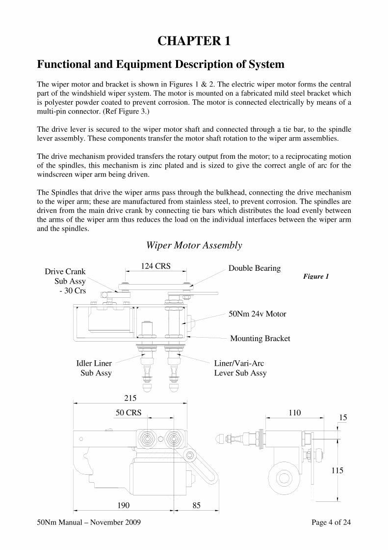
Functional and Equipment Description of System The wiper motor and bracket is shown in Figures 1 & 2. The electric wiper motor forms the central part of the windshield wiper system. The motor is mounted on a fabricated mild steel bracket which is polyester powder coated to prevent corrosion. The motor is connected electrically by means of a multi-pin connector. (Ref Figure 3.) The drive lever is secured to the wiper motor shaft and connected through a tie bar, to the spindle lever assembly. These components transfer the motor shaft rotation to the wiper arm assemblies. The drive mechanism provided transfers the rotary output from the motor; to a reciprocating motion of the spindles, this mechanism is zinc plated and is sized to give the correct angle of arc for the windscreen wiper arm being driven. The Spindles that drive the wiper arms pass through the bulkhead, connecting the drive mechanism to the wiper arm; these are manufactured from stainless steel, to prevent corrosion. The spindles are driven from the main drive crank by connecting tie bars which distributes the load evenly between the arms of the wiper arm thus reduces the load on the individual interfaces between the wiper arm and the spindles.
Wiper Motor Assembly
Figure 1
50 CRS
85190
15
115
110
215
124 CRS
Liner/Vari-Arc Lever Sub Assy
Idler LinerSub Assy
Drive Crank Sub Assy
- 30 Crs
50Nm 24v Motor
Mounting Bracket
Double Bearing

50Nm Manual – November 2009 Page 5 of 24
WIRING CONNECTION CODE
31 0v DC (-ve) Supply
53 Slow Speed
53b Fast Speed
53a 24v DC (+ve) Supply & Self Park
31b Self Park – Reversal Speed
MOTOR CONNECTOR(SHOWN ROTATED 180°)
(FRONT VIEW)
53b
53a
31b
53
31
53
31b
53a
53b
31
31b
53
53a
53b
31
31
53a53
31b 53b
M
SELF PARKREVERSALFEED SLOW FAST
& SELFPARK
SHOWN IN OFF/PARK CONFIGURATION
FEED
(+VE)24v DC
SUPPLY
(+VE)24v DC
SUPPLY
0v DC(-VE)
(8)
(4)
(6)
(2)
Exploded View of Linkage
Electrical Connections
Figure 2
ITEM DESCRIPTION QTY QTY
PANTO PEND
#7* Idler Gasket (Panto Only) 1 -- #8* Idler Plate (Panto Only) 1 --
ITEM DESCRIPTION QTY 9 20mm Washer - Neoprene 2 1 10 20mm Washer – Flat 2 1
1 Motor Mounting Bracket 1 11 20mm Washer – Single Coil 2 1
2 Liner V.Arc Lever Sub Assy 1 12 M20 Hex. Nut 2 1 #3* Idler Liner Sub Assy (Panto Only) 1 13 20mm Weather Cap 2 1
4 Drive Crank Sub Assy 30 Crs 1 14 8mm Washer - Flat 2 1 5 Double Bearing - 124 Crs 1 15 M8 Nylock Nut 2 1 6 50Nm (IER) Motor 1 16 8mm Nut Weather Cap 2 1
OUTSIDE LOOKING IN
INSIDE REAR VIEW
MOTOR
6
#8*
4
SCRAP VIEW- 12v MOTOR
DRIVE CRANK
24v MOTOR
SCRAP VIEWOPPOSITE
HAND PARKING
#7*
#3*
4
1
10
1214
16
1513
119
5
2
50Nm Manual – November 2009 Page 6 of 24
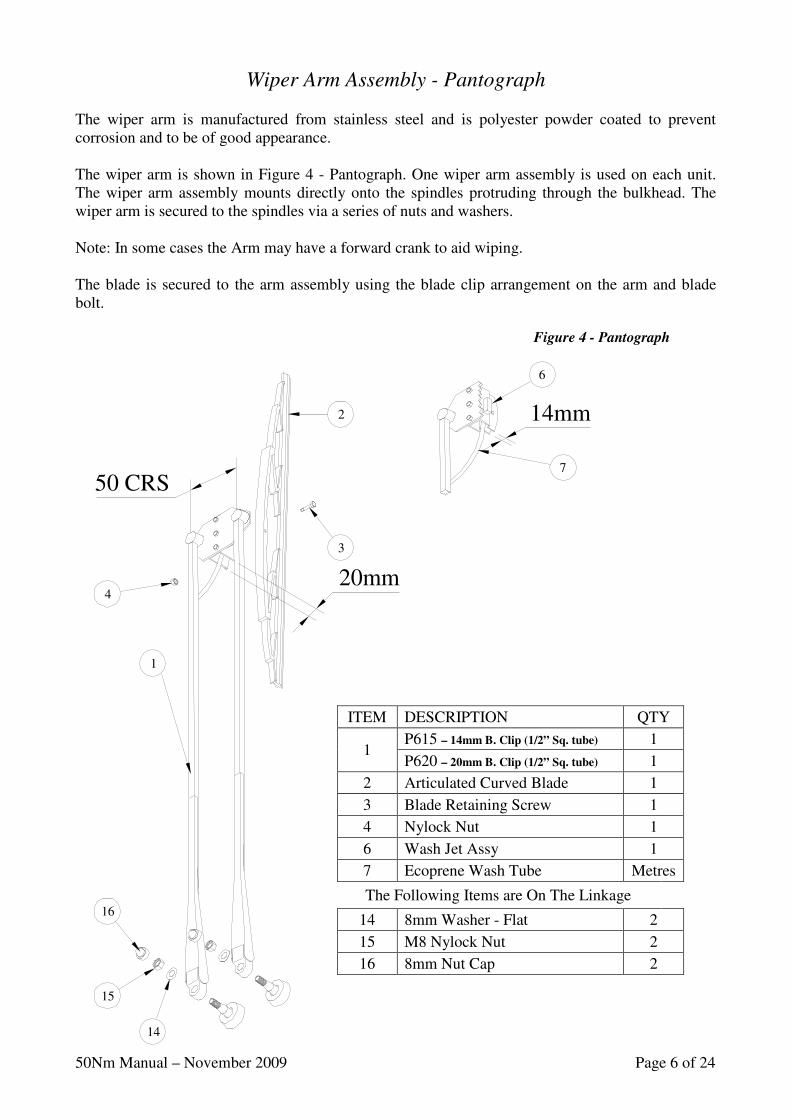
Wiper Arm Assembly - Pantograph The wiper arm is manufactured from stainless steel and is polyester powder coated to prevent corrosion and to be of good appearance. The wiper arm is shown in Figure 4 - Pantograph. One wiper arm assembly is used on each unit. The wiper arm assembly mounts directly onto the spindles protruding through the bulkhead. The wiper arm is secured to the spindles via a series of nuts and washers. Note: In some cases the Arm may have a forward crank to aid wiping. The blade is secured to the arm assembly using the blade clip arrangement on the arm and blade bolt.
ITEM DESCRIPTION QTY
1
P615 – 14mm B. Clip (1/2” Sq. tube) 1
P620 – 20mm B. Clip (1/2” Sq. tube) 1
2 Articulated Curved Blade 1
3 Blade Retaining Screw 1
4 Nylock Nut 1
6 Wash Jet Assy 1
7 Ecoprene Wash Tube Metres
The Following Items are On The Linkage
14 8mm Washer - Flat 2
15 M8 Nylock Nut 2
16 8mm Nut Cap 2
Figure 4 - Pantograph
2
3
1
4
16
15
14
7
6
50 CRS
20mm
14mm
50Nm Manual – November 2009 Page 7 of 24
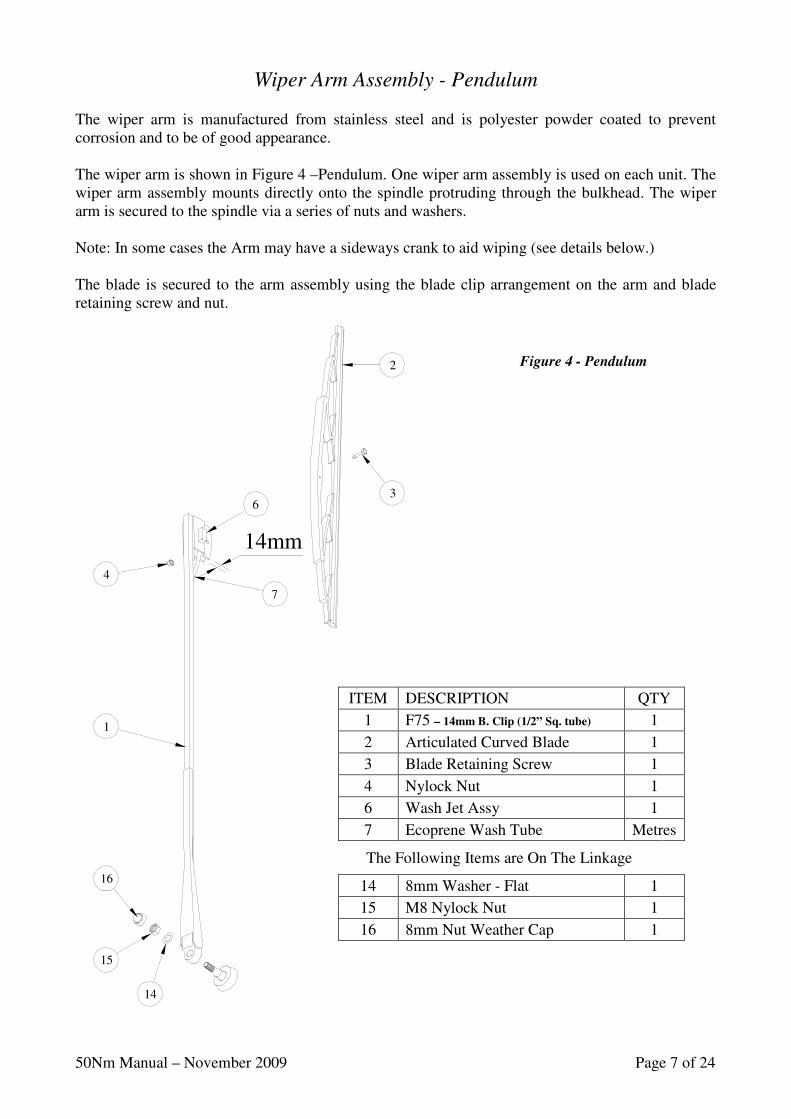
Wiper Arm Assembly - Pendulum The wiper arm is manufactured from stainless steel and is polyester powder coated to prevent corrosion and to be of good appearance. The wiper arm is shown in Figure 4 –Pendulum. One wiper arm assembly is used on each unit. The wiper arm assembly mounts directly onto the spindle protruding through the bulkhead. The wiper arm is secured to the spindle via a series of nuts and washers. Note: In some cases the Arm may have a sideways crank to aid wiping (see details below.) The blade is secured to the arm assembly using the blade clip arrangement on the arm and blade retaining screw and nut.
ITEM DESCRIPTION QTY
1 F75 – 14mm B. Clip (1/2” Sq. tube) 1
2 Articulated Curved Blade 1
3 Blade Retaining Screw 1
4 Nylock Nut 1
6 Wash Jet Assy 1
7 Ecoprene Wash Tube Metres
The Following Items are On The Linkage
14 8mm Washer - Flat 1
15 M8 Nylock Nut 1
16 8mm Nut Weather Cap 1
Figure 4 - Pendulum 2
3
1
4
16
15
14
7
6
14mm
50Nm Manual – November 2009 Page 8 of 24
CHAPTER 2
Installation Instructions
These instructions are meant as a guide. If you experience any difficulty in the fitting of these units, please do not hesitate to contact us for advice.
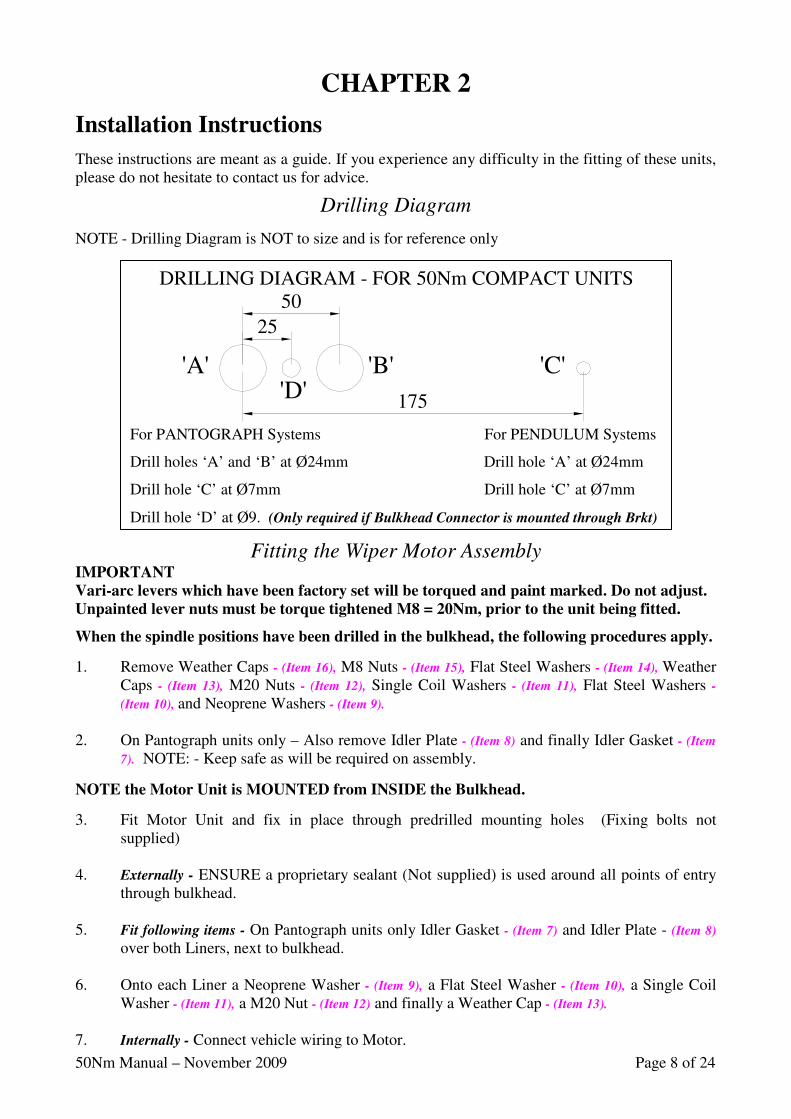
Drilling Diagram
NOTE - Drilling Diagram is NOT to size and is for reference only
Fitting the Wiper Motor Assembly IMPORTANT
Vari-arc levers which have been factory set will be torqued and paint marked. Do not adjust.
Unpainted lever nuts must be torque tightened M8 = 20Nm, prior to the unit being fitted.
When the spindle positions have been drilled in the bulkhead, the following procedures apply.
1. Remove Weather Caps - (Item 16), M8 Nuts - (Item 15), Flat Steel Washers - (Item 14), Weather Caps - (Item 13), M20 Nuts - (Item 12), Single Coil Washers - (Item 11), Flat Steel Washers -
(Item 10), and Neoprene Washers - (Item 9). 2. On Pantograph units only – Also remove Idler Plate - (Item 8) and finally Idler Gasket - (Item
7). NOTE: - Keep safe as will be required on assembly.
NOTE the Motor Unit is MOUNTED from INSIDE the Bulkhead.
3. Fit Motor Unit and fix in place through predrilled mounting holes (Fixing bolts not supplied)
4. Externally - ENSURE a proprietary sealant (Not supplied) is used around all points of entry
through bulkhead. 5. Fit following items - On Pantograph units only Idler Gasket - (Item 7) and Idler Plate - (Item 8)
over both Liners, next to bulkhead. 6. Onto each Liner a Neoprene Washer - (Item 9), a Flat Steel Washer - (Item 10), a Single Coil
Washer - (Item 11), a M20 Nut - (Item 12) and finally a Weather Cap - (Item 13). 7. Internally - Connect vehicle wiring to Motor.
For PANTOGRAPH Systems For PENDULUM Systems
Drill holes ‘A’ and ‘B’ at Ø24mm Drill hole ‘A’ at Ø24mm
Drill hole ‘C’ at Ø7mm Drill hole ‘C’ at Ø7mm
Drill hole ‘D’ at Ø9. (Only required if Bulkhead Connector is mounted through Brkt)
'A' 'B' 'C'
DRILLING DIAGRAM - FOR 50Nm COMPACT UNITS
25
50
175'D'
50Nm Manual – November 2009 Page 9 of 24
2
5
25
26
27
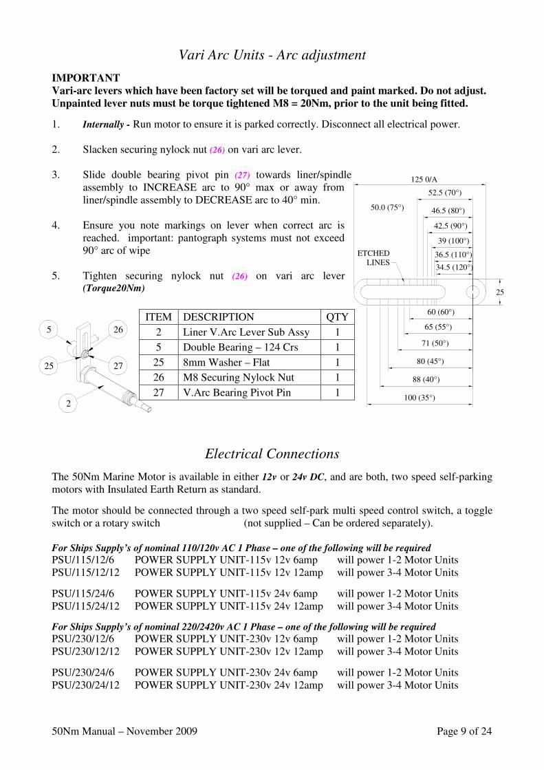
ITEM DESCRIPTION QTY
2 Liner V.Arc Lever Sub Assy 1
5 Double Bearing – 124 Crs 1
25 8mm Washer – Flat 1
26 M8 Securing Nylock Nut 1
27 V.Arc Bearing Pivot Pin 1
125 0/A
52.5 (70°)
46.5 (80°)
100 (35°)
88 (40°)
80 (45°)
71 (50°)
65 (55°)
60 (60°)
25
42.5 (90°)
39 (100°)
36.5 (110°)
34.5 (120°)
50.0 (75°)
ETCHEDLINES
Vari Arc Units - Arc adjustment
IMPORTANT
Vari-arc levers which have been factory set will be torqued and paint marked. Do not adjust.
Unpainted lever nuts must be torque tightened M8 = 20Nm, prior to the unit being fitted.
1. Internally - Run motor to ensure it is parked correctly. Disconnect all electrical power. 2. Slacken securing nylock nut (26) on vari arc lever. 3. Slide double bearing pivot pin (27) towards liner/spindle
assembly to INCREASE arc to 90° max or away from liner/spindle assembly to DECREASE arc to 40° min.
4. Ensure you note markings on lever when correct arc is
reached. important: pantograph systems must not exceed 90° arc of wipe
5. Tighten securing nylock nut (26) on vari arc lever
(Torque20Nm)
Electrical Connections
The 50Nm Marine Motor is available in either 12v or 24v DC, and are both, two speed self-parking motors with Insulated Earth Return as standard.
The motor should be connected through a two speed self-park multi speed control switch, a toggle switch or a rotary switch (not supplied – Can be ordered separately). For Ships Supply’s of nominal 110/120v AC 1 Phase – one of the following will be required
PSU/115/12/6 POWER SUPPLY UNIT-115v 12v 6amp will power 1-2 Motor Units PSU/115/12/12 POWER SUPPLY UNIT-115v 12v 12amp will power 3-4 Motor Units
PSU/115/24/6 POWER SUPPLY UNIT-115v 24v 6amp will power 1-2 Motor Units PSU/115/24/12 POWER SUPPLY UNIT-115v 24v 12amp will power 3-4 Motor Units
For Ships Supply’s of nominal 220/2420v AC 1 Phase – one of the following will be required
PSU/230/12/6 POWER SUPPLY UNIT-230v 12v 6amp will power 1-2 Motor Units PSU/230/12/12 POWER SUPPLY UNIT-230v 12v 12amp will power 3-4 Motor Units
PSU/230/24/6 POWER SUPPLY UNIT-230v 24v 6amp will power 1-2 Motor Units PSU/230/24/12 POWER SUPPLY UNIT-230v 24v 12amp will power 3-4 Motor Units
50Nm Manual – November 2009 Page 10 of 24
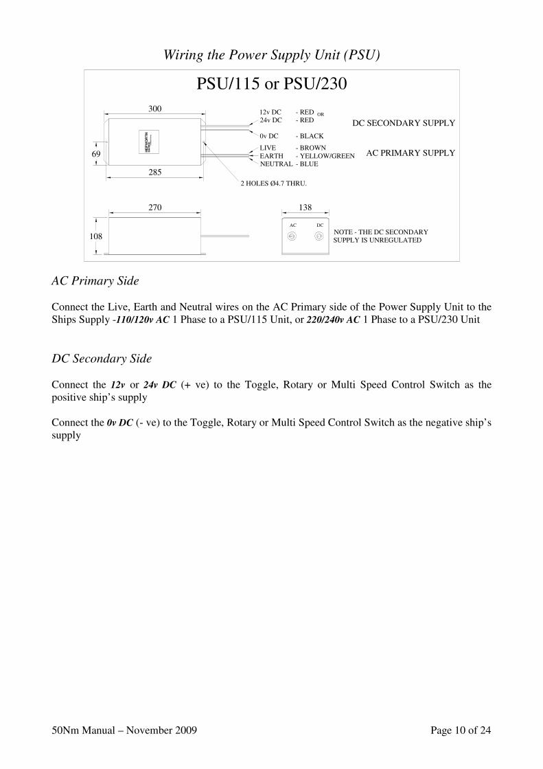
Wiring the Power Supply Unit (PSU)
AC Primary Side Connect the Live, Earth and Neutral wires on the AC Primary side of the Power Supply Unit to the Ships Supply -110/120v AC 1 Phase to a PSU/115 Unit, or 220/240v AC 1 Phase to a PSU/230 Unit
DC Secondary Side Connect the 12v or 24v DC (+ ve) to the Toggle, Rotary or Multi Speed Control Switch as the positive ship’s supply Connect the 0v DC (- ve) to the Toggle, Rotary or Multi Speed Control Switch as the negative ship’s supply
300
108
270 138
285
69
2 HOLES Ø4.7 THRU.
AC DC
12v DC - RED OR 24v DC - RED
0v DC - BLACK
LIVE - BROWN EARTH - YELLOW/GREEN NEUTRAL - BLUE
NOTE - THE DC SECONDARY SUPPLY IS UNREGULATED
DC SECONDARY SUPPLY
AC PRIMARY SUPPLY
PSU/115 or PSU/230
50Nm Manual – November 2009 Page 11 of 24
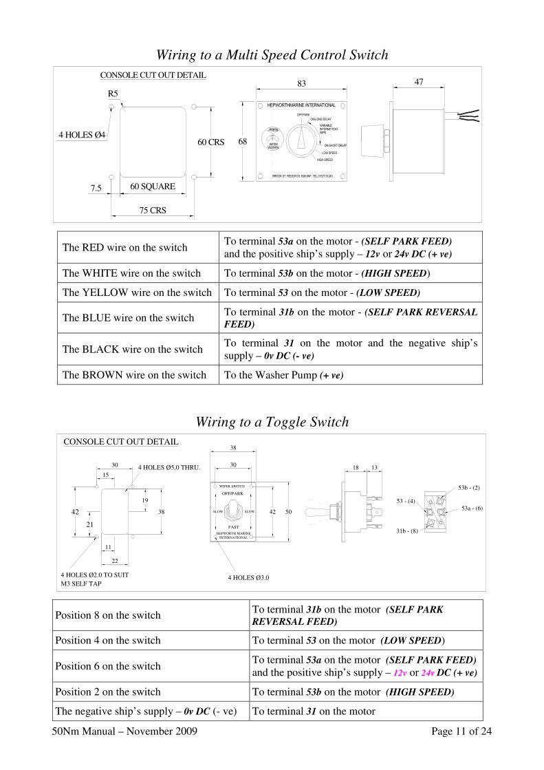
The RED wire on the switch
To terminal 53a on the motor - (SELF PARK FEED) and the positive ship’s supply – 12v or 24v DC (+ ve)
The WHITE wire on the switch
To terminal 53b on the motor - (HIGH SPEED)
The YELLOW wire on the switch
To terminal 53 on the motor - (LOW SPEED)
The BLUE wire on the switch
To terminal 31b on the motor - (SELF PARK REVERSAL
FEED)
The BLACK wire on the switch
To terminal 31 on the motor and the negative ship’s supply – 0v DC (- ve)
The BROWN wire on the switch
To the Washer Pump (+ ve)
WASHER
WIPER
LOW SPEED
HIGH SPEED
ON-SHORT DELAY
PRESS INTERMITTENT
VARIABLE
WIPE
ON-LONG DELAY
OFF/PARK
BROOK ST. REDDITCH. B98 8NF. TEL.01527 61243
83
68
47
75 CRS
R5
7.5 60 SQUARE
4 HOLES Ø460 CRS
CONSOLE CUT OUT DETAIL
HEPWORTHMARINE INTERNATIONAL
Wiring to a Multi Speed Control Switch
Wiring to a Toggle Switch
31b - (8)
53 - (4)53a - (6)
53b - (2)
M3 SELF TAP
19
3842
4 HOLES Ø2.0 TO SUIT
11
22
21
15
30
42 50
INTERNATIONALHEPWORTH MARINE
FAST
OFF/PARK
4 HOLES Ø5.0 THRU.
SLOW
4 HOLES Ø3.0
SLOW
30
38
WIPER SWITCH
18 13
CONSOLE CUT OUT DETAIL
Position 8 on the switch
To terminal 31b on the motor (SELF PARK
REVERSAL FEED)
Position 4 on the switch
To terminal 53 on the motor (LOW SPEED)
Position 6 on the switch
To terminal 53a on the motor (SELF PARK FEED) and the positive ship’s supply – 12v or 24v DC (+ ve)
Position 2 on the switch
To terminal 53b on the motor (HIGH SPEED)
The negative ship’s supply – 0v DC (- ve)
To terminal 31 on the motor
50Nm Manual – November 2009 Page 12 of 24
TO BE AT THECAPTIVE CLIP
TOP OF SCREEN
4
3
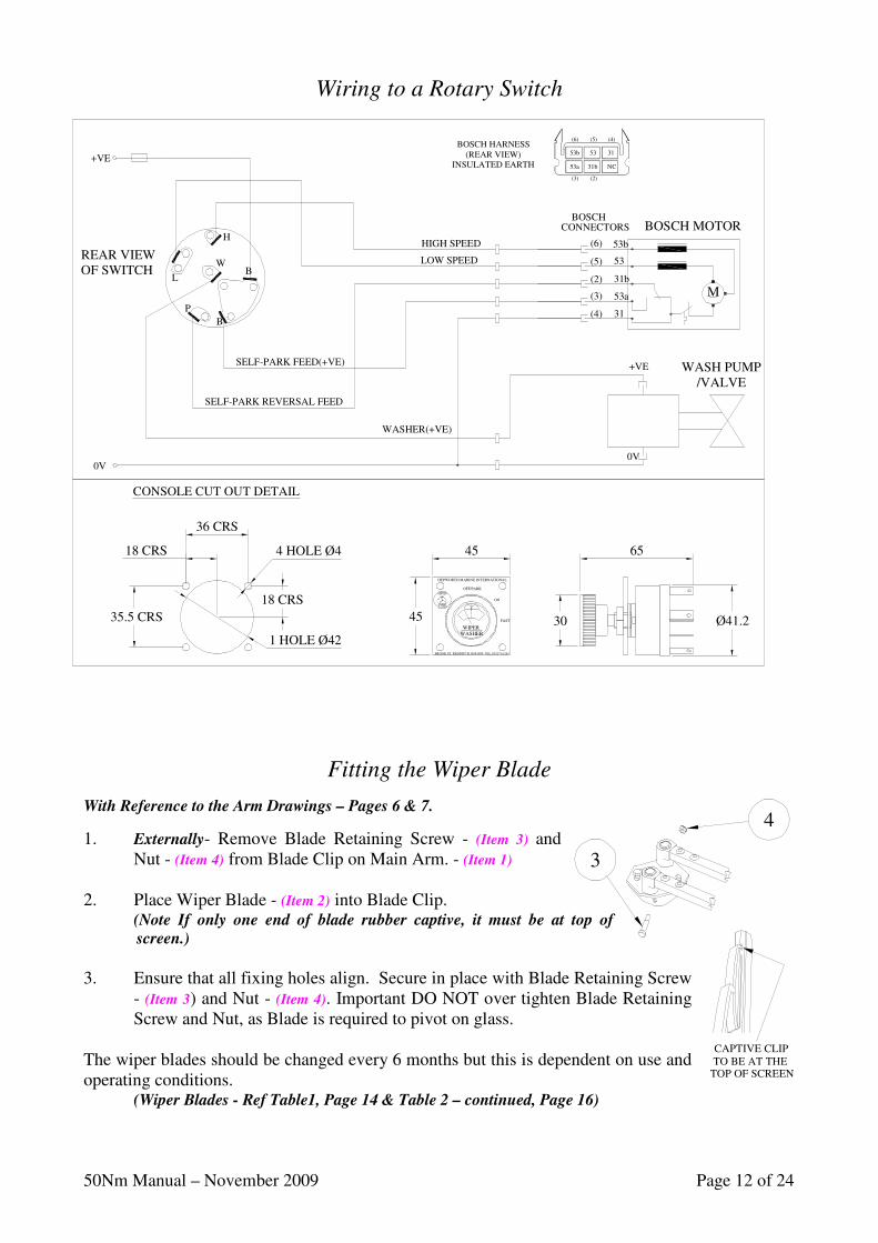
Wiring to a Rotary Switch
Fitting the Wiper Blade
With Reference to the Arm Drawings – Pages 6 & 7.
1. Externally- Remove Blade Retaining Screw - (Item 3) and Nut - (Item 4) from Blade Clip on Main Arm. - (Item 1)
2. Place Wiper Blade - (Item 2) into Blade Clip.
(Note If only one end of blade rubber captive, it must be at top of
screen.)
3. Ensure that all fixing holes align. Secure in place with Blade Retaining Screw
- (Item 3) and Nut - (Item 4). Important DO NOT over tighten Blade Retaining Screw and Nut, as Blade is required to pivot on glass.
The wiper blades should be changed every 6 months but this is dependent on use and operating conditions.
(Wiper Blades - Ref Table1, Page 14 & Table 2 – continued, Page 16)
BROOK ST. REDDITCH. B98 8NF. TEL.01527 61243
OFF/PARK
ON
FAST
HEPWORTH MARINE INTERNATIONAL
WASHERWIPER
30
45
PRESS
WIPER
WASHER
4 HOLE Ø4
CONSOLE CUT OUT DETAIL
35.5 CRS 45
18 CRS
18 CRS
65
1 HOLE Ø42
36 CRS
SELF-PARK FEED(+VE)
0V
SELF-PARK REVERSAL FEED
+VE
P
B
L
W
H
B
WASHER(+VE)
0V
+VE
53b
53a
31b
BOSCH
LOW SPEED
HIGH SPEED
(4)
(3)
31
CONNECTORS
(2)
(5) 53
(6)
BOSCH MOTOR
M
Ø41.2
(3) (2)
(6)
53a
53b 53
31b
(5)
31
NC
(4)BOSCH HARNESS
(REAR VIEW)INSULATED EARTH
REAR VIEW OF SWITCH
WASH PUMP/VALVE
50Nm Manual – November 2009 Page 13 of 24
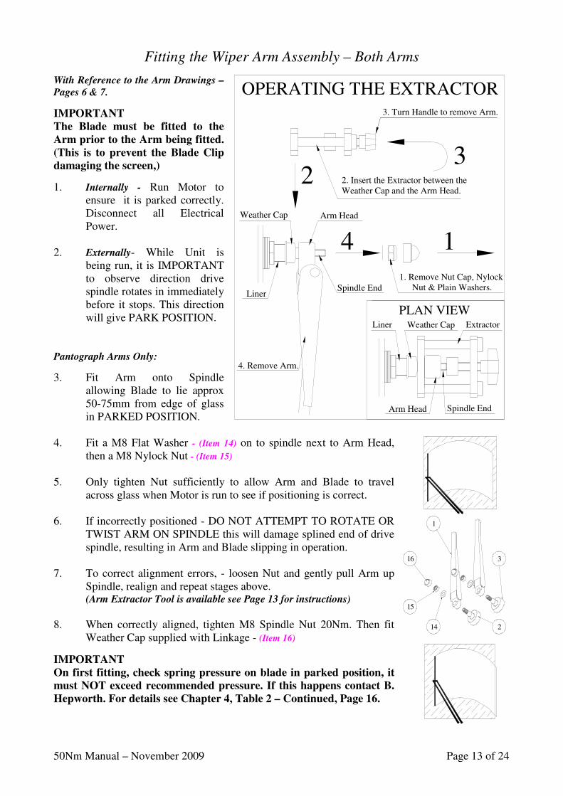
Fitting the Wiper Arm Assembly – Both Arms
With Reference to the Arm Drawings –
Pages 6 & 7.
IMPORTANT
The Blade must be fitted to the
Arm prior to the Arm being fitted.
(This is to prevent the Blade Clip
damaging the screen,)
1. Internally - Run Motor to ensure it is parked correctly. Disconnect all Electrical Power.
2. Externally- While Unit is
being run, it is IMPORTANT to observe direction drive spindle rotates in immediately before it stops. This direction will give PARK POSITION.
Pantograph Arms Only:
3. Fit Arm onto Spindle allowing Blade to lie approx 50-75mm from edge of glass in PARKED POSITION.
4. Fit a M8 Flat Washer - (Item 14) on to spindle next to Arm Head,
then a M8 Nylock Nut - (Item 15) 5. Only tighten Nut sufficiently to allow Arm and Blade to travel
across glass when Motor is run to see if positioning is correct. 6. If incorrectly positioned - DO NOT ATTEMPT TO ROTATE OR
TWIST ARM ON SPINDLE this will damage splined end of drive spindle, resulting in Arm and Blade slipping in operation.
7. To correct alignment errors, - loosen Nut and gently pull Arm up
Spindle, realign and repeat stages above. (Arm Extractor Tool is available see Page 13 for instructions)
8. When correctly aligned, tighten M8 Spindle Nut 20Nm. Then fit
Weather Cap supplied with Linkage - (Item 16)
IMPORTANT
On first fitting, check spring pressure on blade in parked position, it
must NOT exceed recommended pressure. If this happens contact B.
Hepworth. For details see Chapter 4, Table 2 – Continued, Page 16.
1
16
15
14 2
3
2
4
PLAN VIEW
1
3
1. Remove Nut Cap, NylockNut & Plain Washers.
Arm Head Spindle End
Liner Weather Cap Extractor
Weather Cap
Liner
Arm Head
Spindle End
2. Insert the Extractor between the Weather Cap and the Arm Head.
3. Turn Handle to remove Arm.
OPERATING THE EXTRACTOR
4. Remove Arm.
50Nm Manual – November 2009 Page 14 of 24
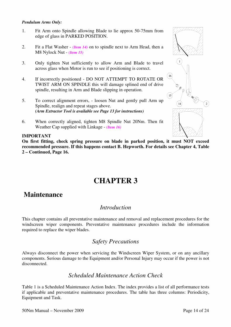
Pendulum Arms Only:
1. Fit Arm onto Spindle allowing Blade to lie approx 50-75mm from edge of glass in PARKED POSITION.
2. Fit a Flat Washer - (Item 14) on to spindle next to Arm Head, then a
M8 Nylock Nut - (Item 15) 3. Only tighten Nut sufficiently to allow Arm and Blade to travel
across glass when Motor is run to see if positioning is correct. 4. If incorrectly positioned - DO NOT ATTEMPT TO ROTATE OR
TWIST ARM ON SPINDLE this will damage splined end of drive spindle, resulting in Arm and Blade slipping in operation.
5. To correct alignment errors, - loosen Nut and gently pull Arm up
Spindle, realign and repeat stages above. (Arm Extractor Tool is available see Page 13 for instructions)
6. When correctly aligned, tighten M8 Spindle Nut 20Nm. Then fit
Weather Cap supplied with Linkage - (Item 16)
IMPORTANT
On first fitting, check spring pressure on blade in parked position, it must NOT exceed
recommended pressure. If this happens contact B. Hepworth. For details see Chapter 4, Table
2 – Continued, Page 16.
CHAPTER 3
Maintenance
Introduction This chapter contains all preventative maintenance and removal and replacement procedures for the windscreen wiper components. Preventative maintenance procedures include the information required to replace the wiper blades.
Safety Precautions Always disconnect the power when servicing the Windscreen Wiper System, or on any ancillary components. Serious damage to the Equipment and/or Personal Injury may occur if the power is not disconnected.
Scheduled Maintenance Action Check Table 1 is a Scheduled Maintenance Action Index. The index provides a list of all performance tests if applicable and preventative maintenance procedures. The table has three columns: Periodicity, Equipment and Task.
1
16
15
14 2
50Nm Manual – November 2009 Page 15 of 24
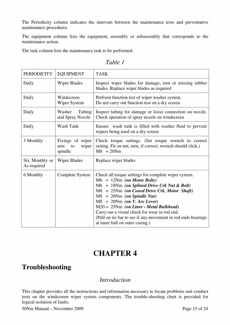
The Periodicity column indicates the intervals between the maintenance tests and preventative maintenance procedures.
The equipment column lists the equipment, assembly or subassembly that corresponds to the maintenance action.
The task column lists the maintenance task to be performed.
Table 1
PERIODICITY
EQUIPMENT
TASK
Daily
Wiper Blades
Inspect wiper blades for damage, torn or missing rubber blades. Replace wiper blades as required
Daily
Windscreen Wiper System
Perform function test of wiper washer system. Do not carry out function test on a dry screen
Daily
Washer Tubing and Spray Nozzle
Inspect tubing for damage or loose connection on nozzle. Check operation of spray nozzle on windscreen
Daily
Wash Tank
Ensure wash tank is filled with washer fluid to prevent wipers being used on a dry screen
3 Monthly
Fixings of wiper arm to wiper spindle
Check torque settings. (Set torque wrench to correct setting. Fit on nut, turn, if correct, wrench should click.) M8 = 20Nm
Six Monthly or As required
Wiper Blades
Replace wiper blades
6 Monthly
Complete System
Check all torque settings for complete wiper system. M6 = 12Nm (on Motor Bolts) M6 = 18Nm (on Splined Drive Crk Nut & Bolt) M8 = 25Nm (on Coned Drive Crk, Motor Shaft) M8 = 20Nm (on Spindle Nut)
M8 = 20Nm (on V. Arc Lever) M20 = 25Nm (on Liner - Metal Bulkhead) Carry out a visual check for wear in rod end. (Pull on tie bar to see if any movement in rod ends bearings at inner ball on outer casing.)
CHAPTER 4
Troubleshooting
Introduction This chapter provides all the instructions and information necessary to locate problems and conduct tests on the windscreen wiper system components. The trouble-shooting chart is provided for logical isolation of faults.
50Nm Manual – November 2009 Page 16 of 24
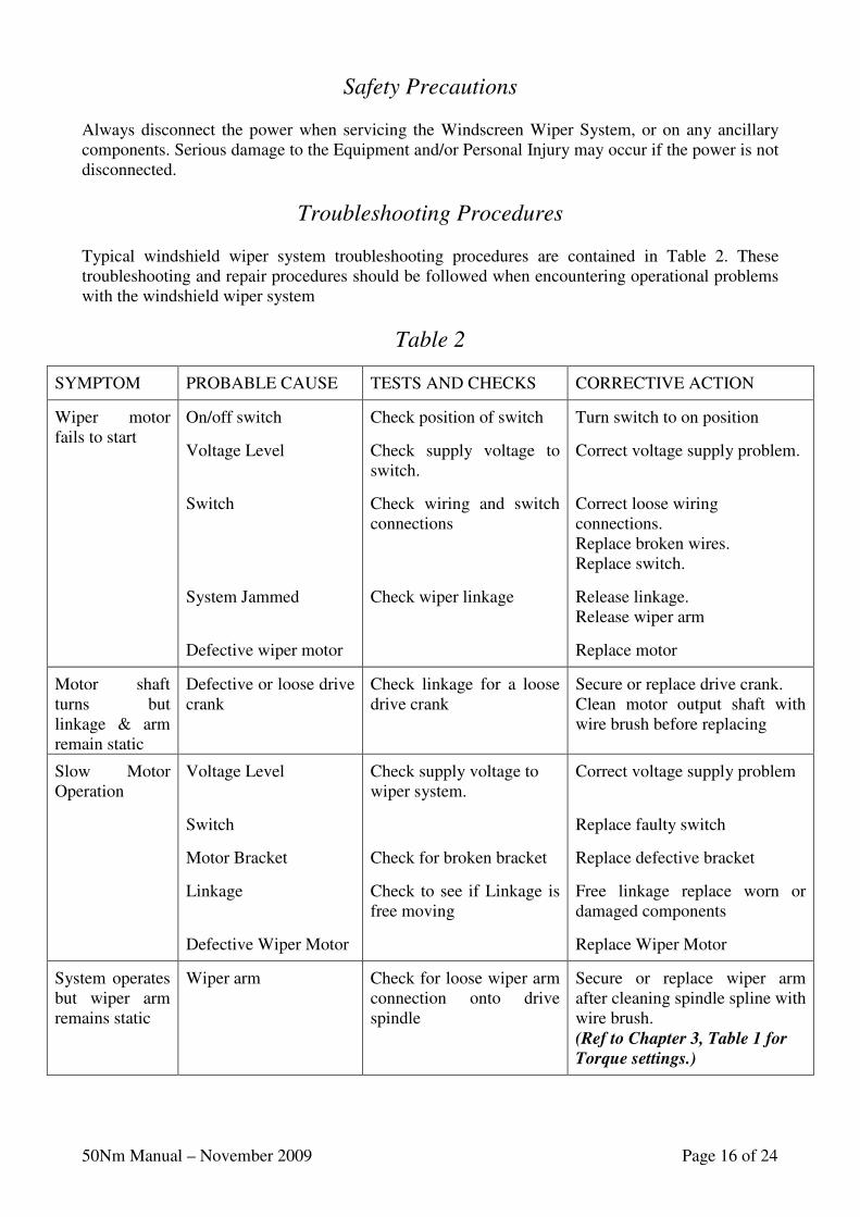
Safety Precautions Always disconnect the power when servicing the Windscreen Wiper System, or on any ancillary components. Serious damage to the Equipment and/or Personal Injury may occur if the power is not disconnected.
Troubleshooting Procedures Typical windshield wiper system troubleshooting procedures are contained in Table 2. These troubleshooting and repair procedures should be followed when encountering operational problems with the windshield wiper system
Table 2
SYMPTOM
PROBABLE CAUSE
TESTS AND CHECKS
CORRECTIVE ACTION
Wiper motor fails to start
On/off switch
Voltage Level
Switch
System Jammed
Defective wiper motor
Check position of switch
Check supply voltage to switch.
Check wiring and switch connections
Check wiper linkage
Turn switch to on position
Correct voltage supply problem.
Correct loose wiring connections. Replace broken wires. Replace switch.
Release linkage. Release wiper arm
Replace motor
Motor shaft turns but linkage & arm remain static
Defective or loose drive crank
Check linkage for a loose drive crank
Secure or replace drive crank. Clean motor output shaft with wire brush before replacing
Slow Motor Operation
Voltage Level
Switch
Motor Bracket
Linkage
Defective Wiper Motor
Check supply voltage to wiper system.
Check for broken bracket
Check to see if Linkage is free moving
Correct voltage supply problem
Replace faulty switch
Replace defective bracket
Free linkage replace worn or damaged components
Replace Wiper Motor
System operates but wiper arm remains static
Wiper arm
Check for loose wiper arm connection onto drive spindle
Secure or replace wiper arm after cleaning spindle spline with wire brush. (Ref to Chapter 3, Table 1 for
Torque settings.)
50Nm Manual – November 2009 Page 17 of 24
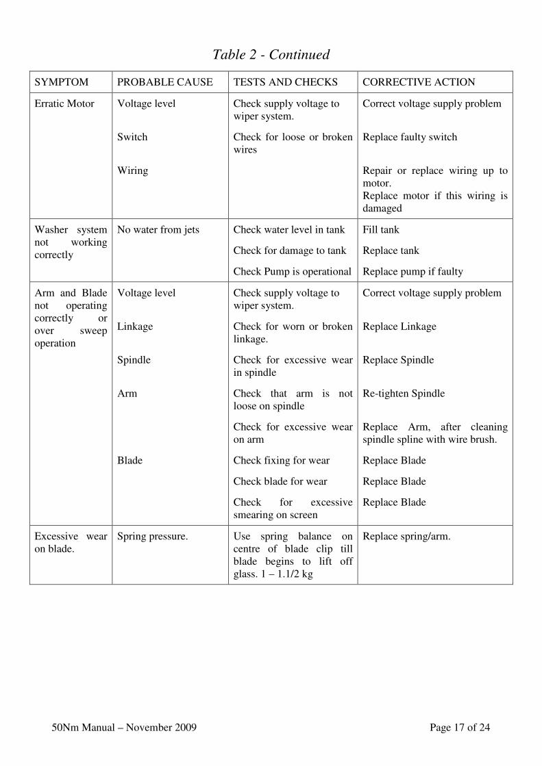
Table 2 - Continued
SYMPTOM
PROBABLE CAUSE
TESTS AND CHECKS
CORRECTIVE ACTION
Erratic Motor
Voltage level
Switch
Wiring
Check supply voltage to wiper system.
Check for loose or broken wires
Correct voltage supply problem
Replace faulty switch
Repair or replace wiring up to motor. Replace motor if this wiring is damaged
Washer system not working correctly
No water from jets
Check water level in tank
Check for damage to tank
Check Pump is operational
Fill tank
Replace tank
Replace pump if faulty
Arm and Blade not operating correctly or over sweep operation
Voltage level
Linkage
Spindle
Arm
Blade
Check supply voltage to wiper system.
Check for worn or broken linkage.
Check for excessive wear in spindle
Check that arm is not loose on spindle
Check for excessive wear on arm
Check fixing for wear
Check blade for wear
Check for excessive smearing on screen
Correct voltage supply problem
Replace Linkage
Replace Spindle
Re-tighten Spindle
Replace Arm, after cleaning spindle spline with wire brush.
Replace Blade
Replace Blade
Replace Blade
Excessive wear on blade.
Spring pressure.
Use spring balance on centre of blade clip till blade begins to lift off glass. 1 – 1.1/2 kg
Replace spring/arm.

50Nm Manual – November 2009 Page 18 of 24
TO BE AT THECAPTIVE CLIP
TOP OF SCREEN
CHAPTER 5
Maintenance Instructions
NOTE: Retain all items removed in a safe place, as they will be required on reassembly. If you experience any difficulty in fitting these units, please do not hesitate to contact us for advice. Use the drawings for reference.
To Replace the Wiper Blade
Removal
With Reference to Figure 4, Page 6.
1. Internally - Run motor to ensure it is parked correctly. Disconnect all electrical power.
2. Externally - Carefully pull wiper arm assembly away from
windscreen to enable access to wiper blade. 3. Remove blade retaining screw - (Item 3), and nut - (Item 4), from blade clip on arm. 4. Remove Blade from Blade Clip on Arm.
Replacement
1. Place wiper blade into blade clip on arm.
NOTE
Captive end on blade rubber to be at top of screen.
2. Ensure that all fixing holes align. Secure in place with blade retaining screw - (Item 3), and nut - (Item 4).
IMPORTANT
Do not over tighten blade screw and nut, as blade is required to pivot on glass.
3. Lower blade carefully back onto windscreen. The wiper blades should be changed every 6 months but this is dependent on use and operating conditions (With Reference to Chapter 3, Table 1 & Chapter 5, Table 2 – continued, Wiper Blades)
To Replace the Wiper Arm
Removal
With Reference to Figure 4, Page 6.
1. Internally - Run motor to ensure it is parked correctly. Disconnect all electrical power. 2. Externally - While Unit is being run it is IMPORTANT to observe direction drive spindle
rotates in, immediately before it stops. This direction will give PARK POSITION.
4
3
50Nm Manual – November 2009 Page 19 of 24
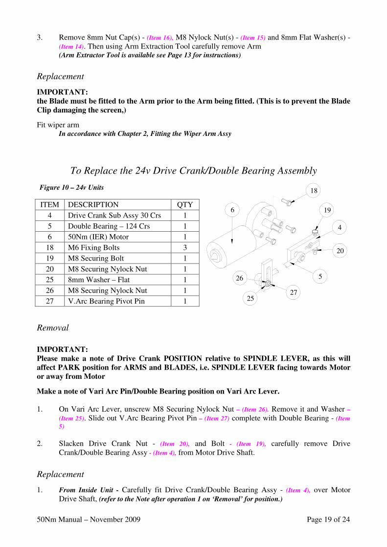
ITEM DESCRIPTION QTY
4 Drive Crank Sub Assy 30 Crs 1
5 Double Bearing – 124 Crs 1
6 50Nm (IER) Motor 1
18 M6 Fixing Bolts 3
19 M8 Securing Bolt 1
20 M8 Securing Nylock Nut 1
25 8mm Washer – Flat 1
26 M8 Securing Nylock Nut 1
27 V.Arc Bearing Pivot Pin 1
Figure 10 – 24v Units
4
20
19
27
526
25
18
6
3. Remove 8mm Nut Cap(s) - (Item 16), M8 Nylock Nut(s) - (Item 15) and 8mm Flat Washer(s) - (Item 14). Then using Arm Extraction Tool carefully remove Arm (Arm Extractor Tool is available see Page 13 for instructions)
Replacement
IMPORTANT:
the Blade must be fitted to the Arm prior to the Arm being fitted. (This is to prevent the Blade
Clip damaging the screen,)
Fit wiper arm In accordance with Chapter 2, Fitting the Wiper Arm Assy
To Replace the 24v Drive Crank/Double Bearing Assembly
Removal
IMPORTANT:
Please make a note of Drive Crank POSITION relative to SPINDLE LEVER, as this will
affect PARK position for ARMS and BLADES, i.e. SPINDLE LEVER facing towards Motor
or away from Motor
Make a note of Vari Arc Pin/Double Bearing position on Vari Arc Lever.
1. On Vari Arc Lever, unscrew M8 Securing Nylock Nut – (Item 26). Remove it and Washer –
(Item 25). Slide out V.Arc Bearing Pivot Pin – (Item 27) complete with Double Bearing - (Item
5) 2. Slacken Drive Crank Nut - (Item 20), and Bolt - (Item 19), carefully remove Drive
Crank/Double Bearing Assy - (Item 4), from Motor Drive Shaft.
Replacement
1. From Inside Unit - Carefully fit Drive Crank/Double Bearing Assy - (Item 4), over Motor Drive Shaft, (refer to the Note after operation 1 on ‘Removal’ for position.)
50Nm Manual – November 2009 Page 20 of 24
2. Fit V.Arc Bearing Pivot Pin – (Item 27) complete with Double Bearing - (Item 5) through Vari Arc Lever. Replacing in same hole position (refer the Note before operation 2 on ‘Removal’ for
position.) for correct setting of arc on replacement 3. Tighten Drive Crank Nut - (Item 20), and Bolt - (Item 19).
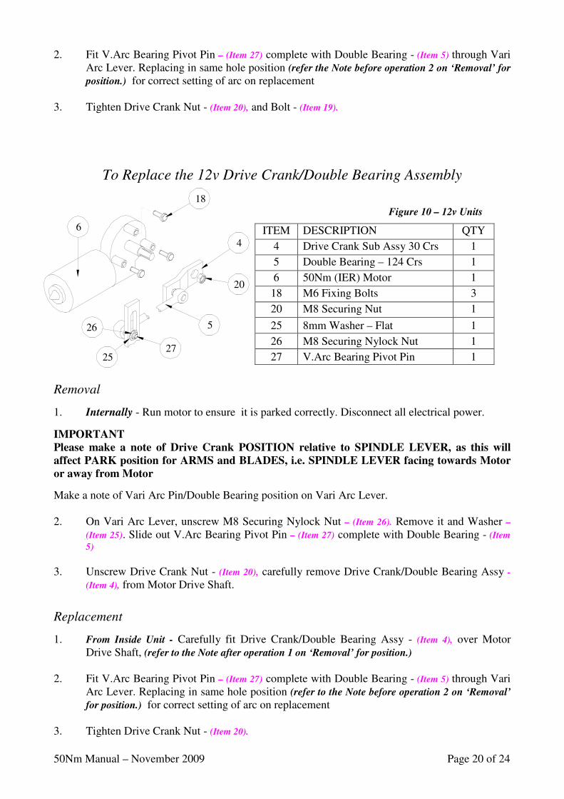
To Replace the 12v Drive Crank/Double Bearing Assembly
Removal
1. Internally - Run motor to ensure it is parked correctly. Disconnect all electrical power.
IMPORTANT
Please make a note of Drive Crank POSITION relative to SPINDLE LEVER, as this will
affect PARK position for ARMS and BLADES, i.e. SPINDLE LEVER facing towards Motor
or away from Motor
Make a note of Vari Arc Pin/Double Bearing position on Vari Arc Lever. 2. On Vari Arc Lever, unscrew M8 Securing Nylock Nut – (Item 26). Remove it and Washer –
(Item 25). Slide out V.Arc Bearing Pivot Pin – (Item 27) complete with Double Bearing - (Item
5) 3. Unscrew Drive Crank Nut - (Item 20), carefully remove Drive Crank/Double Bearing Assy -
(Item 4), from Motor Drive Shaft.
Replacement
1. From Inside Unit - Carefully fit Drive Crank/Double Bearing Assy - (Item 4), over Motor Drive Shaft, (refer to the Note after operation 1 on ‘Removal’ for position.)
2. Fit V.Arc Bearing Pivot Pin – (Item 27) complete with Double Bearing - (Item 5) through Vari
Arc Lever. Replacing in same hole position (refer to the Note before operation 2 on ‘Removal’
for position.) for correct setting of arc on replacement 3. Tighten Drive Crank Nut - (Item 20).
Figure 10 – 12v Units
ITEM DESCRIPTION QTY
4 Drive Crank Sub Assy 30 Crs 1
5 Double Bearing – 124 Crs 1
6 50Nm (IER) Motor 1
18 M6 Fixing Bolts 3
20 M8 Securing Nut 1
25 8mm Washer – Flat 1
26 M8 Securing Nylock Nut 1
27 V.Arc Bearing Pivot Pin 1
27
6
5
20
4
26
25
18
50Nm Manual – November 2009 Page 21 of 24
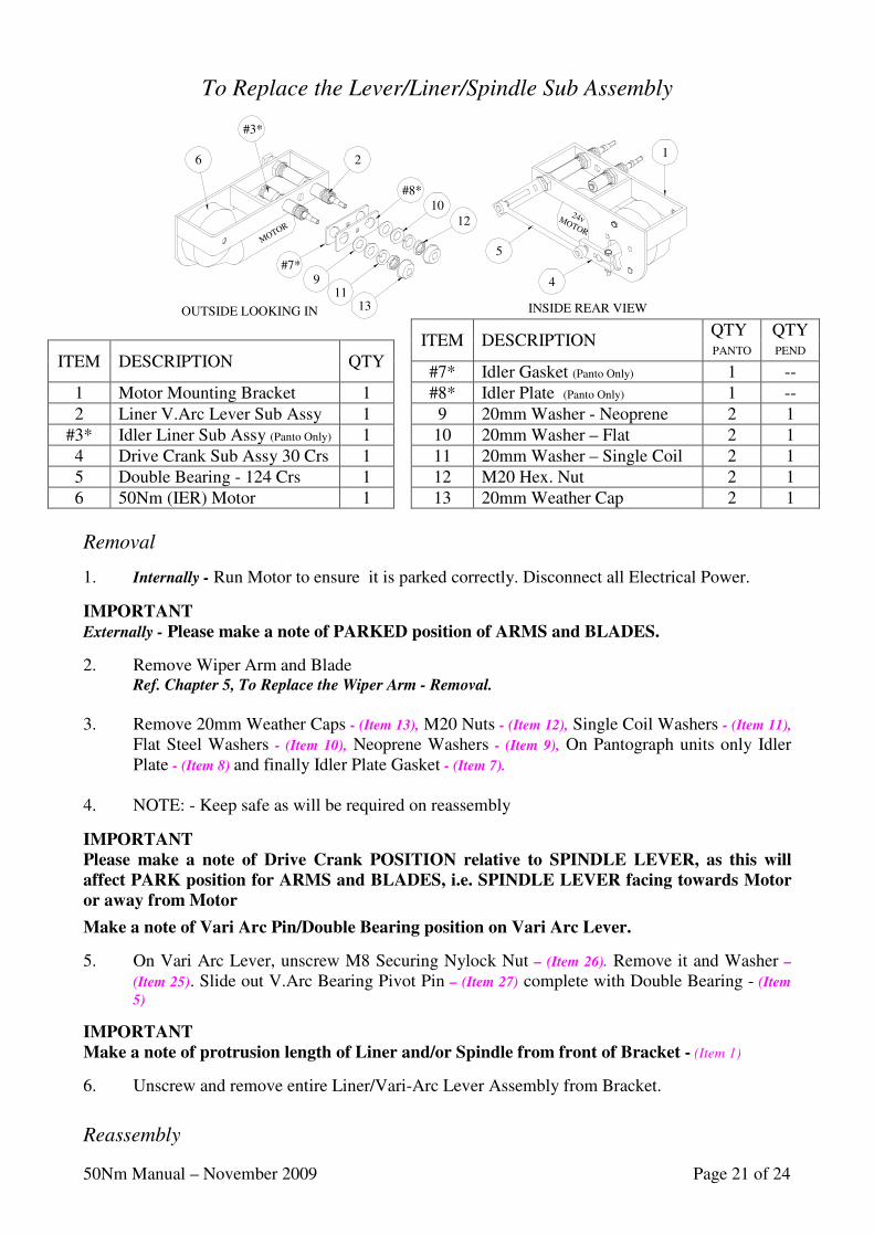
To Replace the Lever/Liner/Spindle Sub Assembly
Removal
1. Internally - Run Motor to ensure it is parked correctly. Disconnect all Electrical Power.
IMPORTANT
Externally - Please make a note of PARKED position of ARMS and BLADES.
2. Remove Wiper Arm and Blade Ref. Chapter 5, To Replace the Wiper Arm - Removal.
3. Remove 20mm Weather Caps - (Item 13), M20 Nuts - (Item 12), Single Coil Washers - (Item 11),
Flat Steel Washers - (Item 10), Neoprene Washers - (Item 9), On Pantograph units only Idler Plate - (Item 8) and finally Idler Plate Gasket - (Item 7).
4. NOTE: - Keep safe as will be required on reassembly
IMPORTANT
Please make a note of Drive Crank POSITION relative to SPINDLE LEVER, as this will
affect PARK position for ARMS and BLADES, i.e. SPINDLE LEVER facing towards Motor
or away from Motor
Make a note of Vari Arc Pin/Double Bearing position on Vari Arc Lever.
5. On Vari Arc Lever, unscrew M8 Securing Nylock Nut – (Item 26). Remove it and Washer –
(Item 25). Slide out V.Arc Bearing Pivot Pin – (Item 27) complete with Double Bearing - (Item
5)
IMPORTANT
Make a note of protrusion length of Liner and/or Spindle from front of Bracket - (Item 1)
6. Unscrew and remove entire Liner/Vari-Arc Lever Assembly from Bracket.
Reassembly
OUTSIDE LOOKING IN INSIDE REAR VIEW
MOTOR
6
#8*
4
24v MOTOR
#7*
#3*
1
1012
1311
9
5
2
ITEM DESCRIPTION
QTY QTY
ITEM DESCRIPTION QTY PANTO PEND
#7* Idler Gasket (Panto Only) 1 --
1 Motor Mounting Bracket 1 #8* Idler Plate (Panto Only) 1 --
2 Liner V.Arc Lever Sub Assy 1 9 20mm Washer - Neoprene 2 1
#3* Idler Liner Sub Assy (Panto Only) 1 10 20mm Washer – Flat 2 1 4 Drive Crank Sub Assy 30 Crs 1 11 20mm Washer – Single Coil 2 1
5 Double Bearing - 124 Crs 1 12 M20 Hex. Nut 2 1 6 50Nm (IER) Motor 1 13 20mm Weather Cap 2 1
50Nm Manual – November 2009 Page 22 of 24
1. Screw entire Liner/Vari- Arc Lever Assembly into Bracket. 2. Fit V.Arc Bearing Pivot Pin – (Item 27) complete with Double Bearing - (Item 5) through Vari
Arc Lever. Replacing in same hole position (refer Note before operation 5 on ‘Removal’ for
position.) for correct setting of arc on replacement 3. Replace Liner Nuts and Weather Caps on to Liners. Replace Arm and Blade
(Refer to fitting instructions for replacement)
Vari Arc Units - Arc adjustment For Instructions on adjustment see Diagram, Page 9
CHAPTER 6
Operation Instructions
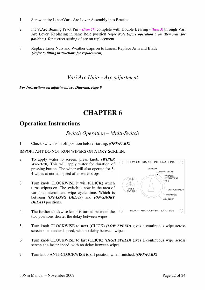
Switch Operation – Multi-Switch 1. Check switch is in off position before starting. (OFF/PARK)
IMPORTANT DO NOT RUN WIPERS ON A DRY SCREEN.
2. To apply water to screen, press knob. (WIPER
WASHER) This will apply water for duration of pressing button. The wiper will also operate for 3-4 wipes at normal speed after water stops.
3. Turn knob CLOCKWISE it will (CLICK) which
turns wipers on. The switch is now in the area of variable intermittent wipe cycle time. Which is between (ON-LONG DELAY) and (ON-SHORT
DELAY) positions. 4. The further clockwise knob is turned between the
two positions shorter the delay between wipes. 5. Turn knob CLOCKWISE to next (CLICK) (LOW SPEED) gives a continuous wipe across
screen at a standard speed, with no delay between wipes. 6. Turn knob CLOCKWISE to last (CLICK) (HIGH SPEED) gives a continuous wipe across
screen at a faster speed, with no delay between wipes. 7. Turn knob ANTI-CLOCKWISE to off position when finished. (OFF/PARK)
WASHER
WIPER
LOW SPEED
HIGH SPEED
ON-SHORT DELAY
PRESS INTERMITTENT
VARIABLE
WIPE
ON-LONG DELAY
OFF/PARK
BROOK ST. REDDITCH. B98 8NF. TEL.01527 61243
HEPWORTHMARINE INTERNATIONAL
50Nm Manual – November 2009 Page 23 of 24
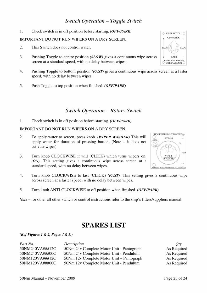
Switch Operation – Toggle Switch 1. Check switch is in off position before starting. (OFF/PARK)
IMPORTANT DO NOT RUN WIPERS ON A DRY SCREEN.
2. This Switch does not control water. 3. Pushing Toggle to centre position (SLOW) gives a continuous wipe across
screen at a standard speed, with no delay between wipes. 4. Pushing Toggle to bottom position (FAST) gives a continuous wipe across screen at a faster
speed, with no delay between wipes. 5. Push Toggle to top position when finished. (OFF/PARK)
Switch Operation – Rotary Switch 1. Check switch is in off position before starting. (OFF/PARK)
IMPORTANT DO NOT RUN WIPERS ON A DRY SCREEN.
2. To apply water to screen, press knob. (WIPER WASHER) This will apply water for duration of pressing button. (Note – it does not activate wiper)
3. Turn knob CLOCKWISE it will (CLICK) which turns wipers on,
(ON). This setting gives a continuous wipe across screen at a standard speed, with no delay between wipes.
4. Turn knob CLOCKWISE to last (CLICK) (FAST). This setting gives a continuous wipe
across screen at a faster speed, with no delay between wipes. 5. Turn knob ANTI-CLOCKWISE to off position when finished. (OFF/PARK) Note – for other all other switch or control instructions refer to the ship’s fitters/suppliers manual.
SPARES LIST
(Ref Figures 1 & 2, Pages 4 & 5.)
Part No. Description Qty
50NM240VA###12C 50Nm 24v Complete Motor Unit - Pantograph As Required 50NM240VA###00C 50Nm 24v Complete Motor Unit - Pendulum As Required 50NM120VA###12C 50Nm 12v Complete Motor Unit – Pantograph As Required 50NM120VA###00C 50Nm 12v Complete Motor Unit - Pendulum As Required
INTERNATIONALHEPWORTH MARINE
FAST
OFF/PARK
SLOW SLOW
WIPER SWITCH
BROOK ST. REDDITCH. B98 8NF. TEL.01527 61243
OFF/PARK
ON
FAST
HEPWORTH MARINE INTERNATIONAL
WASHERWIPER
PRESS
WIPERWASHER
50Nm Manual – November 2009 Page 24 of 24
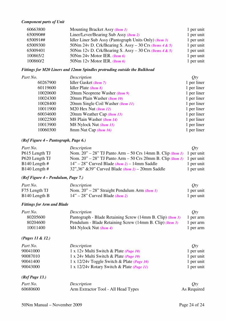
Component parts of Unit
60663800 Mounting Bracket Assy (Item 1) 1 per unit 650090## Liner/Lever/Bearing Sub Assy (Item 2) 1 per unit 650091## Idler Liner Sub Assy (Pantograph Units Only) (Item 3) 1 per unit 65009300 50Nm 24v D. Crk/Bearing S. Assy – 30 Crs (Items 4 & 5) 1 per unit 65009401 50Nm 12v D. Crk/Bearing S. Assy – 30 Crs (Items 4 & 5) 1 per unit 100865/2 50Nm 24v Motor IER. (Item 6) 1 per unit 100860/2 50Nm 12v Motor IER. (Item 6) 1 per unit
Fittings for M20 Liners and 12mm Spindles protruding outside the Bulkhead
Part No. Description Qty
60267900 Idler Gasket (Item 7) 1 per liner 60119600 Idler Plate (Item 8) 1 per liner 10020600 20mm Neoprene Washer (Item 9) 1 per liner 10024300 20mm Plain Washer (Item 10) 1 per liner 10028400 20mm Single Coil Washer (Item 11) 1 per liner 10011900 M20 Hex Nut (Item 12) 1 per liner 60034600 20mm Weather Cap (Item 13) 1 per liner 10022500 M8 Plain Washer (Item 14) 1 per liner 10013900 M8 Nylock Nut (Item 15) 1 per liner 10060300 8mm Nut Cap (Item 16) 1 per liner (Ref Figure 4 – Pantograph, Page 6.)
Part No. Description Qty
P615 Length TJ Nom. 20” – 28” TJ Panto Arm – 50 Crs 14mm B. Clip (Item 1) 1 per unit P620 Length TJ Nom. 20” – 28” TJ Panto Arm – 50 Crs 20mm B. Clip (Item 1) 1 per unit B140 Length # 14” – 28” Curved Blade (Item 2) – 14mm Saddle 1 per unit B140 Length # 32”,36” &39” Curved Blade (Item 2) – 20mm Saddle 1 per unit
(Ref Figure 4 – Pendulum, Page 7.)
Part No. Description Qty
F75 Length TJ Nom. 20” – 28” Straight Pendulum Arm (Item 1) 1 per unit B140 Length B 14” – 28” Curved Blade (Item 2) 1 per unit
Fittings for Arm and Blade
Part No. Description Qty
80205600 Pantograph - Blade Retaining Screw (14mm B. Clip) (Item 3) 1 per arm 80204600 Pendulum - Blade Retaining Screw (14mm B. Clip) (Item 3) 1 per arm 10011400 M4 Nylock Nut (Item 4) 1 per arm (Pages 11 & 12.)
Part No. Description Qty
90041000 1 x 12v Multi Switch & Plate (Page 10) 1 per unit 90087010 1 x 24v Multi Switch & Plate (Page 10) 1 per unit 90041400 1 x 12/24v Toggle Switch & Plate (Page 10) 1 per unit 90043000 1 x 12/24v Rotary Switch & Plate (Page 11) 1 per unit (Ref Page 13.)
Part No. Description Qty
60680600 Arm Extractor Tool - All Head Types As Required