Embed Size (px)
Citation preview

5 Power sections for converters - IndraDrive C5.1 Types
Converter Types Features
HCS02 W0012W0028W0054W0070
Compact modular design1.5 kW to 11 kWContinuous currents up to 28 A
HCS03 W0070W0100W0150W0210W0280W0350
Compact modular design25 kW to 120 kWContinuous currents up to 200 A
Tab. 5-1: Types
5.2 HCS02 Power sections5.2.1 Brief description, use and design
Short description The compact converters HCS02 are part of the Rexroth IndraDrive C productrange and are used to operate single axes.
Use The different types are used as follows:
Type Use
HCS02.1E-Wxxxx-NNNNHCS02.1E-Wxxxx-NNNV
Operation of a three-phase a.c. motor(asynchronous or synchronous motor) inthe power range from 1.5 kW to 11 kW.
HCS02.1E-Wxxxx-LxxNLoad-dependent fan control
Applications with operation at partial loadand requirement of a low degree of noisedevelopment.
Tab. 5-2: Usage of HCS02
DOK-INDRV*-HMV-S-D+HCS-PR04-EN-P Bosch Rexroth AG 35/425Rexroth IndraDrive Supply Units, Power Sections HMV, HMS, HMD, HCS02, HCS03
Power sections for converters - IndraDrive C
Structure, block diagrams
1 Power section2 Control sectionFig. 5-1: Basic Structure of the Drive Controller
Bosch Rexroth AG DOK-INDRV*-HMV-S-D+HCS-PR04-EN-P36/425Rexroth IndraDrive Supply Units, Power Sections HMV, HMS, HMD, HCS02, HCS03
Power sections for converters - IndraDrive C
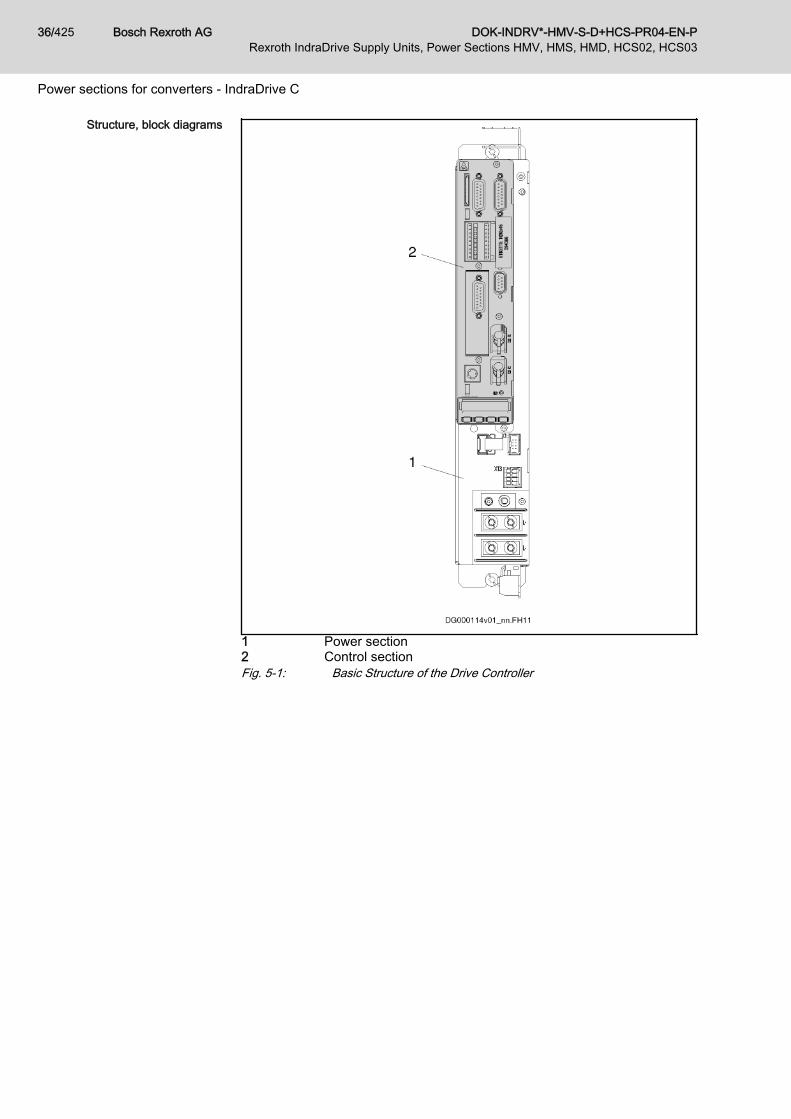
HCS02.1E-W0012-NNNN; -LNNN
1) Mains input with rectifier2) Braking resistor circuit; charging current limitation3) DC bus capacitances4) Inverter stage with output to motorFig. 5-2: HCS02.1E-W0012-NNNN , -LNNN - Block DiagramHCS02.1E-W0012-NNNV
1) Mains input with rectifier2) Optional integrated control voltage supply3) Braking resistor circuit; charging current limitation4) DC bus capacitances5) Inverter stage with output to motorFig. 5-3: HCS02.1E-W0012-NNNV - Block Diagram
DOK-INDRV*-HMV-S-D+HCS-PR04-EN-P Bosch Rexroth AG 37/425Rexroth IndraDrive Supply Units, Power Sections HMV, HMS, HMD, HCS02, HCS03
Power sections for converters - IndraDrive C

HCS02.1E-W0028-NNNN; -LNNN
1) Mains input with rectifier2) Braking resistor circuit; charging current limitation3) DC bus capacitances4) Inverter stage with output to motor5) DC bus connectionFig. 5-4: HCS02.1E-W0028-NNNN; -LNNN - Block DiagramHCS02.1E-W0028-NNNV
1) Mains input with rectifier2) Optional integrated control voltage supply3) Braking resistor circuit; charging current limitation4) DC bus capacitances5) Inverter stage with output to motor6) DC bus connectionFig. 5-5: HCS02.1E-W0028-NNNV - Block Diagram
Bosch Rexroth AG DOK-INDRV*-HMV-S-D+HCS-PR04-EN-P38/425Rexroth IndraDrive Supply Units, Power Sections HMV, HMS, HMD, HCS02, HCS03
Power sections for converters - IndraDrive C

HCS02.1E-W0054/70-NNNN; -LNNN
1) Mains input with rectifier2) Braking resistor circuit; charging current limitation3) Optional external braking resistor (activated via parameter
"P-0-0860, Converter configuration")4) DC bus capacitances5) Inverter stage with output to motor6) DC bus connectionFig. 5-6: HCS02.1E-W0054/70-NNNN; -LNNN - Block DiagramHCS02.1E-W0054/70-NNNV
1) Mains input with rectifier2) Optional integrated control voltage supply3) Braking resistor circuit; charging current limitation4) Optional external braking resistor (activated via parameter
"P-0-0860, Converter configuration")5) DC bus capacitances6) Inverter stage with output to motor7) DC bus connectionFig. 5-7: HCS02.1E-W0054/70-NNNV - Block Diagram
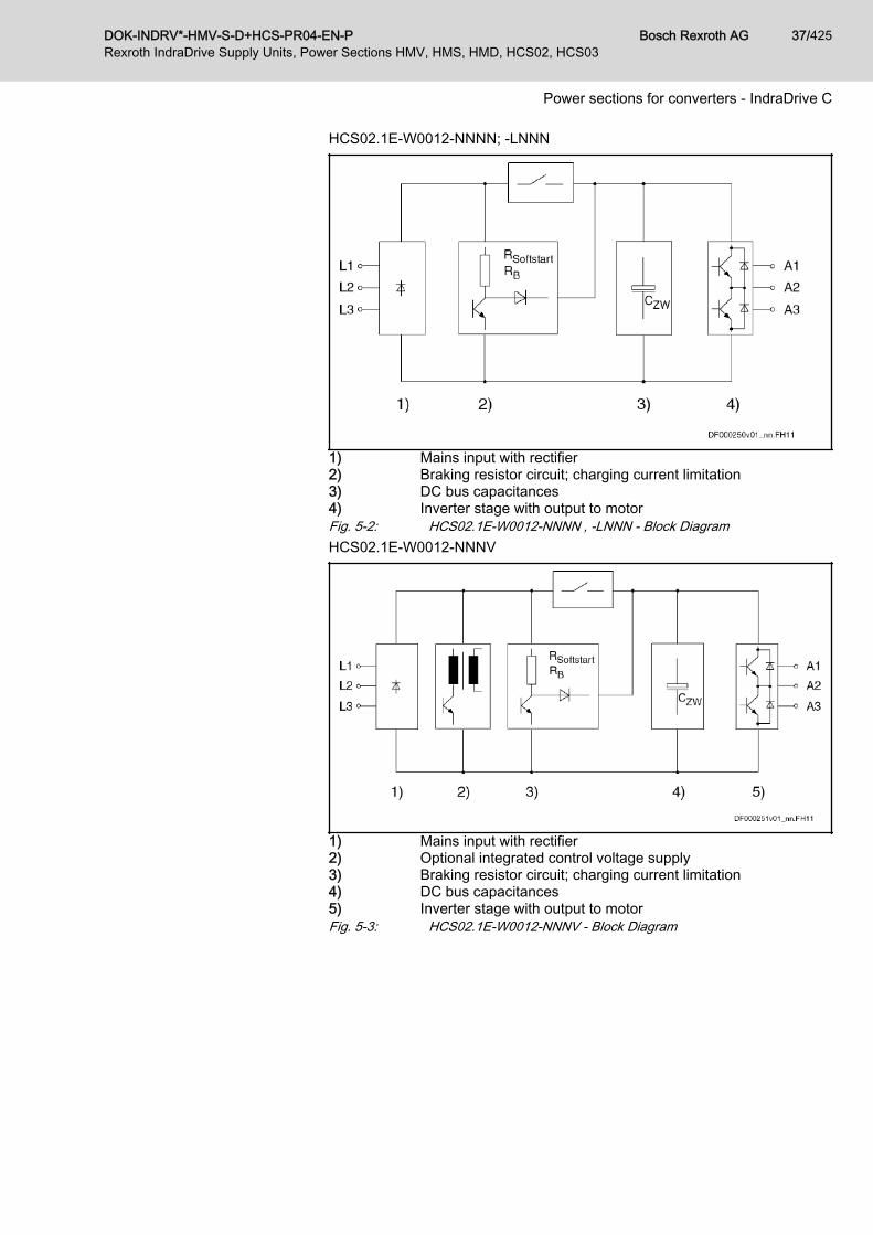
5.2.2 Type code and identificationType Code
The following figure illustrates the basic structure of the typecode. Our sales representative will help you with the current sta‐tus of available versions.
DOK-INDRV*-HMV-S-D+HCS-PR04-EN-P Bosch Rexroth AG 39/425Rexroth IndraDrive Supply Units, Power Sections HMV, HMS, HMD, HCS02, HCS03
Power sections for converters - IndraDrive C
Fig. 5-8: Type Code HCS02
Bosch Rexroth AG DOK-INDRV*-HMV-S-D+HCS-PR04-EN-P40/425Rexroth IndraDrive Supply Units, Power Sections HMV, HMS, HMD, HCS02, HCS03
Power sections for converters - IndraDrive C

IdentificationType plate arrangement
1 power section type plate2 control section type plateFig. 5-9: Type plate arrangement
DOK-INDRV*-HMV-S-D+HCS-PR04-EN-P Bosch Rexroth AG 41/425Rexroth IndraDrive Supply Units, Power Sections HMV, HMS, HMD, HCS02, HCS03
Power sections for converters - IndraDrive C

Type plate (power sections, supplyunits)
1 Device type2 Part number3 Serial number4 Bar code5 Country of manufacture6 Production week; e.g. 08W23 meaning year 2008, week 237 Hardware indexFig. 5-10: Type Plate (Power Sections, Supply Units)
5.2.3 Scope of supply● 1 × touch guard● Connectors for the electrical connection points at the device● 1 × Instruction Manual (in the English language)
5.2.4 Technical dataAmbient and operating conditions
General informationConditions for transport and storage: See chapter 4.2 "Transport and stor‐age" on page 29.Installation conditions: See chapter 4.3 "Installation conditions" on page 30.This chapter contains:● Limit values for use in the scope of CSA / UL● Applied standards (CE conformity, UL listing)
UL DataAmbient and operating conditions - UL ratings
Description Symbol Unit HCS02.1E-W0012-_-03
HCS02.1E-W0028-_-03
HCS02.1E-W0054-_-03
HCS02.1E-W0070-_-03
Short circuit current rating SCCR A rms 42000
Rated input voltage, power1) ULN_nenn V 3 x AC 200...500
Rated input current ILN A 6.0 13.0 20.0 30.0
Output voltage Uout V 3 x AC 0...530
Output current Iout A 4.5 12.0 20.6 28.0
Last modification: 2017-01-23
1) Mains input L1, L2, L3 (for HMV and HCS only); For use on asolidly grounded wye source only.
Tab. 5-3: HCS - Ambient and operating conditions - UL ratings
Bosch Rexroth AG DOK-INDRV*-HMV-S-D+HCS-PR04-EN-P42/425Rexroth IndraDrive Supply Units, Power Sections HMV, HMS, HMD, HCS02, HCS03
Power sections for converters - IndraDrive C

Information on standards Applied Standards
Description Symbol Unit HCS02.1E-W0012-_-03
HCS02.1E-W0028-_-03
HCS02.1E-W0054-_-03
HCS02.1E-W0070-_-03
Listing in accordance with ULstandard UL 508C
UL-Files E134201
Listing in accordance with CSAstandard C22.2 No. 274-13
Last modification: 2017-01-23
Tab. 5-4: HCS - Applied Standards
DOK-INDRV*-HMV-S-D+HCS-PR04-EN-P Bosch Rexroth AG 43/425Rexroth IndraDrive Supply Units, Power Sections HMV, HMS, HMD, HCS02, HCS03
Power sections for converters - IndraDrive C

Mechanics and mountingDimensional drawings
Dimensional drawing HCS02.1E-W0012
A Minimum mounting clearance (when using accessoryHAS02.1); plus additional space for cable
B minimum mounting clearance; plus additional space for cableFig. 5-11: Dimensional drawing HCS02.1E-W0012
Bosch Rexroth AG DOK-INDRV*-HMV-S-D+HCS-PR04-EN-P44/425Rexroth IndraDrive Supply Units, Power Sections HMV, HMS, HMD, HCS02, HCS03
Power sections for converters - IndraDrive C

Dimensional drawing HCS02.1E-W0028
A Minimum mounting clearance (when using accessoryHAS02.1); plus additional space for cable
B minimum mounting clearance; plus additional space for cableFig. 5-12: Dimensional drawing HCS02.1E-W0028
DOK-INDRV*-HMV-S-D+HCS-PR04-EN-P Bosch Rexroth AG 45/425Rexroth IndraDrive Supply Units, Power Sections HMV, HMS, HMD, HCS02, HCS03
Power sections for converters - IndraDrive C
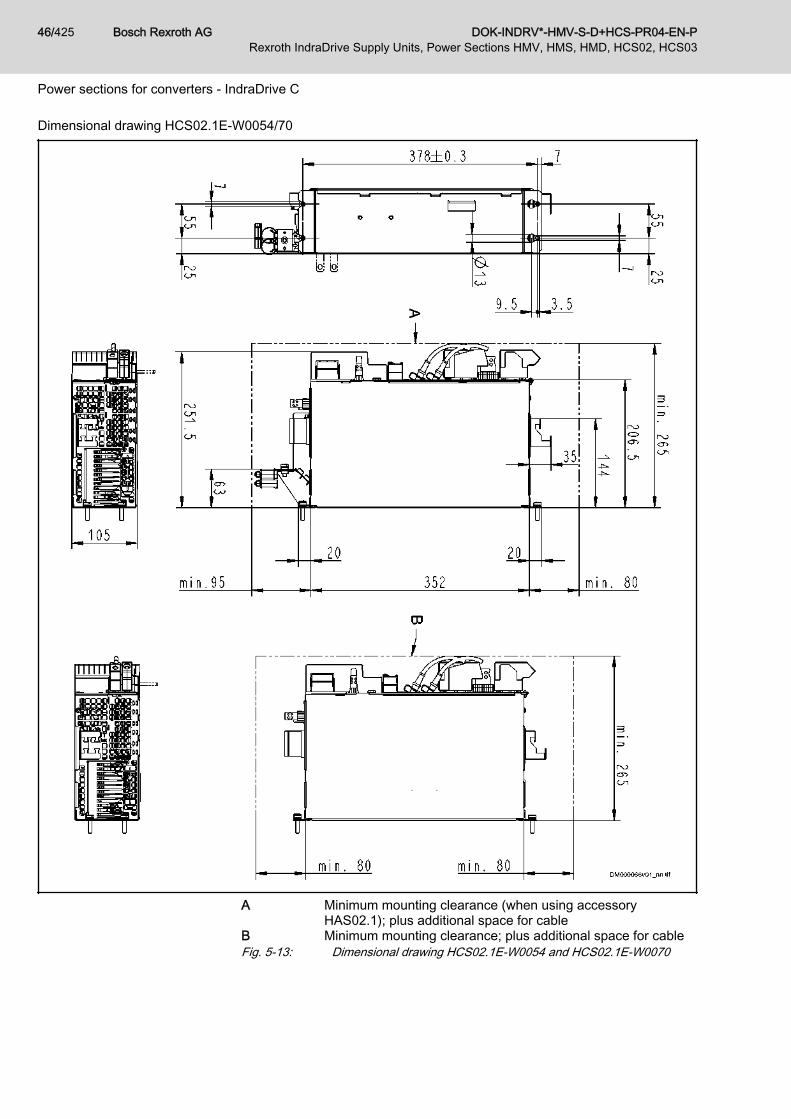
Dimensional drawing HCS02.1E-W0054/70
A Minimum mounting clearance (when using accessoryHAS02.1); plus additional space for cable
B Minimum mounting clearance; plus additional space for cableFig. 5-13: Dimensional drawing HCS02.1E-W0054 and HCS02.1E-W0070
Bosch Rexroth AG DOK-INDRV*-HMV-S-D+HCS-PR04-EN-P46/425Rexroth IndraDrive Supply Units, Power Sections HMV, HMS, HMD, HCS02, HCS03
Power sections for converters - IndraDrive C

Dimensions, mass, insulation, sound pressure levelData for mass, sound pressure level, insulation
Description Symbol Unit HCS02.1E-W0012-_-03
HCS02.1E-W0028-_-03
HCS02.1E-W0054-_-03
HCS02.1E-W0070-_-03
Mass m kg 2.90 3.80 6.70 6.80
Device height1) H mm 290 352
Device depth2) T mm 206
Device width3) B mm 65 105
Insulation resistance at 500 V DC Ris MOhm 1.00 8.00
Capacitance against housing CY nF 2 x 100
Average sound pressure level (ac‐curacy class 2) at PDC_cont
4) LP dB (A) 60 61
Last modification: 2010-08-04
1) 2) 3) Housing dimension; see also related dimensional drawing4) According to DIN EN ISO 11205; comparative value at dis‐
tance 1 m, out of cabinet; HCS types with order code -L***:load-dependent
Tab. 5-5: HCS - Data for mass, dimensions, sound pressure level, insulationTemperature-dependent fan con‐
trolIn devices of the order code "-L***", the internal fan of the cooling system iscontrolled depending on the temperature of the cooling system. As the loadincreases, the temperature at the heat sink rises and thereby the sound pres‐sure level according to the characteristic below. The specified "averagesound pressure level LP" applies to operation under rated conditions.
TKK temperature at heat sinkLP average sound pressure level1 HCS02.1E-W0054/W0070-…-L***2 HCS02.1E-W0012/W0028-…-L***Fig. 5-14: Characteristic of Sound Pressure Level for HCS02 with Order Code
"-L***"
DOK-INDRV*-HMV-S-D+HCS-PR04-EN-P Bosch Rexroth AG 47/425Rexroth IndraDrive Supply Units, Power Sections HMV, HMS, HMD, HCS02, HCS03
Power sections for converters - IndraDrive C

Power dissipation, mounting position, cooling, distancesCooling and power dissipation data
Description Symbol Unit HCS02.1E-W0012-_-03
HCS02.1E-W0028-_-03
HCS02.1E-W0054-_-03
HCS02.1E-W0070-_-03
Ambient temperature range foroperation with nominal data Ta_work °C 0...40
Ambient temperature range foroperation with reduced nominaldata
Ta_work_red °C 0...55
fTa %/K 2.0
Allowed mounting position G1
Cooling type Forced ventilation
Volumetric capacity of forced cool‐ing V m3/h Approx. 24 Approx. 40
Allowed switching frequencies1) fs kHz 4, 8, 12, 16
Power dissipation at Iout_cont = 0 A;fs = fs (min.)2)
PDiss_0A_fs
minW 25 35 85
Power dissipation at Iout_cont = 0 A;fs = fs (max.)3)
PDiss_0A_fs
maxW 70 110 195 185
Power dissipation at continuouscurrent and continuous DC buspower respectively4)
PDiss_cont W 80.00 130.00 270.00 300.00
Minimum distance on the top ofthe device5) dtop mm 80
Minimum distance on the bottomof the device6) dbot mm 80
Temperature increase with mini‐mum distances dbot; dtop; PBD
ΔT K 12 40 50
Last modification: 2014-09-23
1) Also depending on firmware and control section; see parame‐ter description "P-0-0001, Switching frequency of the poweroutput stage"; see "P-0-4058, Amplifier type data"; for supplyunits the switching frequency is 4.2 kHz
2) 3) Plus dissipation of braking resistor and control section; find in‐terim values by interpolation to P_Diss_cont
4) Plus dissipation of braking resistor and control section5) 6) See fig. "Air intake and air outlet at device"Tab. 5-6: HCS - Data for cooling and power dissipation
Bosch Rexroth AG DOK-INDRV*-HMV-S-D+HCS-PR04-EN-P48/425Rexroth IndraDrive Supply Units, Power Sections HMV, HMS, HMD, HCS02, HCS03
Power sections for converters - IndraDrive C

Property damage due to temperatures higherthan 105 ℃!
NOTICE
Observe the indicated minimum distances!Above the devices there may only be such materials which● are not combustible● are insensitive to the occurring high temperatures
A Air intakeB Air outletC Mounting surface in control cabinetdtop Distance topdbot Distance bottomdhor Distance horizontalFig. 5-15: Air intake and air outlet at device
Power dissipation vs. output cur‐rent
The figure below illustrates the connection between power dissipation andoutput current, depending on the switching frequency fs which was set at thedrive controller. See also Parameter Description "P-0-0001, Switching fre‐quency of the power output stage".
In addition, take the power at the braking resistor and the powerconsumption of the control section into account. Both powers arenot contained in the figure.
DOK-INDRV*-HMV-S-D+HCS-PR04-EN-P Bosch Rexroth AG 49/425Rexroth IndraDrive Supply Units, Power Sections HMV, HMS, HMD, HCS02, HCS03
Power sections for converters - IndraDrive C

Iout Output currentPDiss Power dissipationfs Switching frequencyFig. 5-16: Power Dissipation vs. Output CurrentFor the data PDiss_cont, PDiss_0A_fsmax and PDiss_0A_fsmin, see the table "Data forCooling and Power Dissipation".
Basic data power section HCS02General informationThis section contains● Data for control voltage supply● Data for mains voltage supply● Data of DC bus● Data of integrated braking resistor and requirements on an external
braking resistor● Data of inverter● Data for cooling and power dissipation
The order of the data tables below follows the energy flow in thedrive controller - from mains connection to motor output.
Bosch Rexroth AG DOK-INDRV*-HMV-S-D+HCS-PR04-EN-P50/425Rexroth IndraDrive Supply Units, Power Sections HMV, HMS, HMD, HCS02, HCS03
Power sections for converters - IndraDrive C
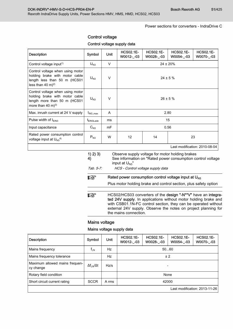
Control voltageControl voltage supply data
Description Symbol Unit HCS02.1E-W0012-_-03
HCS02.1E-W0028-_-03
HCS02.1E-W0054-_-03
HCS02.1E-W0070-_-03
Control voltage input1) UN3 V 24 ± 20%
Control voltage when using motorholding brake with motor cablelength less than 50 m (HCS01less than 40 m)2)
UN3 V 24 ± 5 %
Control voltage when using motorholding brake with motor cablelength more than 50 m (HCS01more than 40 m)3)
UN3 V 26 ± 5 %
Max. inrush current at 24 V supply IIN3_max A 2.80
Pulse width of IEIN3 tEIN3Lade ms 15
Input capacitance CN3 mF 0.56
Rated power consumption controlvoltage input at UN3
4) PN3 W 12 14 23
Last modification: 2010-08-04
1) 2) 3) Observe supply voltage for motor holding brakes4) See information on "Rated power consumption control voltage
input at UN3"Tab. 5-7: HCS - Control voltage supply data
Rated power consumption control voltage input at UN3
Plus motor holding brake and control section, plus safety option
HCS02/HCS03 converters of the design "-N**V" have an integra‐ted 24V supply. In applications without motor holding brake andwith CSB01.1N-FC control section, they can be operated withoutexternal 24V supply. Observe the notes on project planning forthe mains connection.
Mains voltageMains voltage supply data
Description Symbol Unit HCS02.1E-W0012-_-03
HCS02.1E-W0028-_-03
HCS02.1E-W0054-_-03
HCS02.1E-W0070-_-03
Mains frequency fLN Hz 50...60
Mains frequency tolerance Hz ± 2
Maximum allowed mains frequen‐cy change ΔfLN/Δt Hz/s -
Rotary field condition None
Short circuit current rating SCCR A rms 42000
Last modification: 2013-11-26
DOK-INDRV*-HMV-S-D+HCS-PR04-EN-P Bosch Rexroth AG 51/425Rexroth IndraDrive Supply Units, Power Sections HMV, HMS, HMD, HCS02, HCS03
Power sections for converters - IndraDrive C

Description Symbol Unit HCS02.1E-W0012-_-03
HCS02.1E-W0028-_-03
HCS02.1E-W0054-_-03
HCS02.1E-W0070-_-03
Nominal mains voltage ULN_nenn V 3 AC 400
Single-phase mains voltage ULN V 200...250
Three-phase mains voltage at TN-S, TN-C, TT mains ULN V 200...500
Three-phase mains voltage at ITmains1) ULN V 200...230
Three-phase mains voltage atCorner-grounded-Delta mains2) ULN V 200...230
Tolerance rated input voltage ULN % ± 10
Minimum short circuit power of themains for failure-free operation Sk_min MVA 0.2 0.4 0.6 0.8
Minimum inductance of mainssupply (mains phase inductance)3) Lmin µH 40
Assigned type of mains choke HNL01.1E-1000-N0012-A-500-NNNN
HNL01.1E-1000-N0020-
A-500-NNNN
HNL01.1E-0600-N0032-
A-500-NNNN
Inrush currentIL_trans_max
_onA 1.4...4.3 3.5...10.7 6.3...19.3 9.9...27.5
Maximum allowed ON-OFF cyclesper minute4) 1
Mains input continuous current atULN_nenn and PDC_cont (single-phase, without mains choke)5)
ILN A -
Mains input continuous current atULN_nenn and PDC_cont (three-phase,without mains choke)6)
ILN A 6.00 13.00 20.00 30.00
Mains input continuous current atULN_nenn and PDC_cont (single-phase, with mains choke)7)
ILN A -
Mains input continuous current atULN_nenn and PDC_cont (three-phase,with mains choke)8)
ILN A -
Nominal current AC1 for mainscontactor at nom. data I LN
Mains fuse according toEN 60204-1 (single-phase, with‐out mains choke)
A -
Mains fuse according toEN 60204-1 (three-phase, withoutmains choke)
A tbd
Last modification: 2013-11-26
Bosch Rexroth AG DOK-INDRV*-HMV-S-D+HCS-PR04-EN-P52/425Rexroth IndraDrive Supply Units, Power Sections HMV, HMS, HMD, HCS02, HCS03
Power sections for converters - IndraDrive C

Description Symbol Unit HCS02.1E-W0012-_-03
HCS02.1E-W0028-_-03
HCS02.1E-W0054-_-03
HCS02.1E-W0070-_-03
Mains fuse according toEN 60204-1 (single-phase, withmains choke)
A -
Mains fuse according toEN 60204-1 (three-phase, withmains choke)
A 10 16 25 35
Required wire size in accordancewith NFPA 79 and UL 508 A (in‐ternal wiring);9)
ALN AWG 14 AWG 12 AWG 10 AWG
Mains connection power atULN_nenn and PDC_cont (three-phase,without mains choke)
SLN kVA 3.50 8.50 11.00 16.00
Mains connection power atULN_nenn and PDC_cont (three-phase,with mains choke)
SLN kVA 3.50 7.30 13.30 18.50
Mains connection power atULN_nenn and PDC_cont (single-phase, without mains choke)
SLN kVA -
Mains connection power atULN_nenn and PDC_cont (single-phase, with mains choke)
SLN kVA -
Power factor TPF (λL) at ULN_nenn
and PDC_cont (single-phase, withoutmains choke)10)
TPF 0.40
Power factor TPF (λL) at ULN_nenn
and PDC_cont (three-phase, withoutmains choke)11)
TPF 0.60 0.64 0.56
Power factor TPF (λL) at ULN_nenn
and PDC_cont (single-phase, withmains choke)12)
TPF -
Power factor TPF (λL) at ULN_nenn
and PDC_cont (three-phase, withmains choke)13)
TPF - 0.70 0.75 0.76
Power factor TPF (λL) at ULN_nenn
and 10% PDC_cont (single-phase,without mains choke)
TPF10% -
Power factor TPF (λL) at ULN_nenn
and 10% PDC_cont (three-phase,without mains choke)
TPF10% 0.40
Power factor TPF (λL) at ULN_nenn
and 10% PDC_cont (single-phase,with mains choke)
TPF10% -
Last modification: 2013-11-26
DOK-INDRV*-HMV-S-D+HCS-PR04-EN-P Bosch Rexroth AG 53/425Rexroth IndraDrive Supply Units, Power Sections HMV, HMS, HMD, HCS02, HCS03
Power sections for converters - IndraDrive C
Description Symbol Unit HCS02.1E-W0012-_-03
HCS02.1E-W0028-_-03
HCS02.1E-W0054-_-03
HCS02.1E-W0070-_-03
Power factor TPF (λL) at ULN_nenn
and 10% PDC_cont (three-phase,with mains choke)
TPF10% -
Power factor of fundamental com‐ponent DPF at PDC_cont (single-phase, without mains choke)
cosφh1 -
Power factor of fundamental com‐ponent DPF at PDC_cont (three-phase, without mains choke)
cosφh1 0.97
Power factor of fundamental com‐ponent DPF at PDC_cont (single-phase, with mains choke)
cosφh1 -
Power factor of fundamental com‐ponent DPF at PDC_cont (three-phase, with mains choke)
cosφh1 0.95
Last modification: 2013-11-26
1) 2) Mains voltage > ULN: Use a transformer withgrounded neutral point, do not use autotransform‐ers!
3) Otherwise use HNL mains choke4) Observe allowed number of switch-on processes;
without external capacitors at the DC bus5) 6) 7) 8) 10) 11) 12) 13) Find interim values by interpolation9) Copper wire; PVC-insulation (conductor tempera‐
ture 90 °C; Ta ≤ 40 °C) in accordance withNFPA 79 chapter 12 and UL 508A chapter 28
Tab. 5-8: HCS - Mains voltage supply data
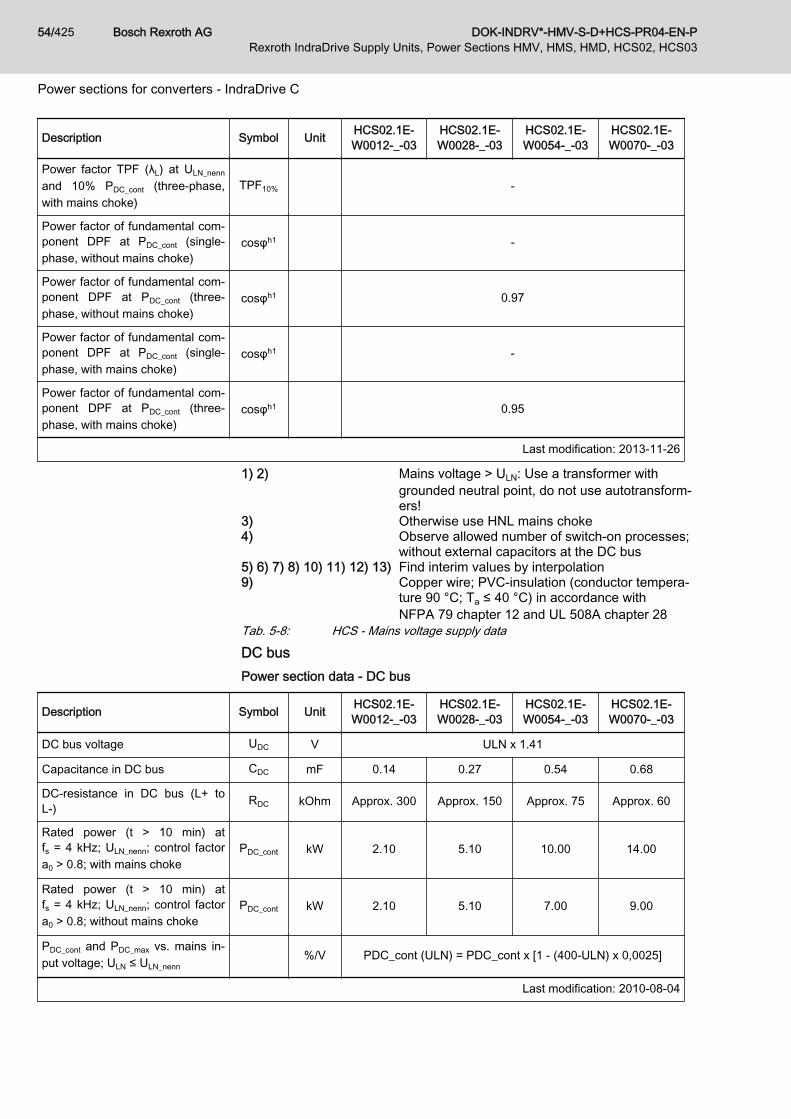
DC busPower section data - DC bus
Description Symbol Unit HCS02.1E-W0012-_-03
HCS02.1E-W0028-_-03
HCS02.1E-W0054-_-03
HCS02.1E-W0070-_-03
DC bus voltage UDC V ULN x 1.41
Capacitance in DC bus CDC mF 0.14 0.27 0.54 0.68
DC-resistance in DC bus (L+ toL-) RDC kOhm Approx. 300 Approx. 150 Approx. 75 Approx. 60
Rated power (t > 10 min) atfs = 4 kHz; ULN_nenn; control factora0 > 0.8; with mains choke
PDC_cont kW 2.10 5.10 10.00 14.00
Rated power (t > 10 min) atfs = 4 kHz; ULN_nenn; control factora0 > 0.8; without mains choke
PDC_cont kW 2.10 5.10 7.00 9.00
PDC_cont and PDC_max vs. mains in‐put voltage; ULN ≤ ULN_nenn
%/V PDC_cont (ULN) = PDC_cont x [1 - (400-ULN) x 0,0025]
Last modification: 2010-08-04
Bosch Rexroth AG DOK-INDRV*-HMV-S-D+HCS-PR04-EN-P54/425Rexroth IndraDrive Supply Units, Power Sections HMV, HMS, HMD, HCS02, HCS03
Power sections for converters - IndraDrive C

Description Symbol Unit HCS02.1E-W0012-_-03
HCS02.1E-W0028-_-03
HCS02.1E-W0054-_-03
HCS02.1E-W0070-_-03
PDC_cont and PDC_max vs. mains in‐put voltage; ULN > ULN_nenn
%/V PDC_cont (ULN) = PDC_cont x [1 + (ULN-400) x 0,002]
Maximum allowed DC bus powerat ULN_nenn; with mains choke PDC_max kW 5.00 10.00 16.00 19.00
Maximum allowed DC bus powerat ULN_nenn; without mains choke PDC_max kW 5.00 8.00 12.00 14.00
Balancing factor for PDC_cont (forparallel operation at common DCbus) with mains choke
- 0.80
Balancing factor for PDC_cont (forparallel operation at common DCbus) without mains choke
- 0.50
Monitoring value maximum DCbus voltage, switch-off threshold
UDC_lim‐
it_maxV 900
Monitoring value minimum DC busvoltage, undervoltage threshold
UDC_lim‐
it_minV can be parameterized, see "P-0-0114, Undervoltage threshold"
Charging resistor continuous pow‐er PDC_Start kW 0.05 0.15 0.35 0.50
Allowed external DC bus capaci‐tance (nom.) at ULN_nenn
1) CDCext mF - 5.00 7.00 13.00
Charging time at maximum al‐lowed CDCext external DC bus ca‐pacitance at ULN_nenn
tlade_DC_Ce
xts 2.00
Last modification: 2010-08-04
1) Use assigned mains chokeTab. 5-9: HCS - Power section data - DC bus
Single-phase mains connection Single-phase mains connectionSingle-phase mains connection is carried out via the connectionsL1 and L2.The maximum allowed DC bus power PDC_max is limited to thespecified continuous power PDC_cont_1ph.
Data of power section with single-phase mains connection
Description Symbol Unit HCS02.1E-W0012-_-03
HCS02.1E-W0028-_-03
HCS02.1E-W0054-_-03
HCS02.1E-W0070-_-03
Single-phase mains voltage ULN V 200...250
continuous power (t > 10 min) PDC_cont_1ph W 50...70 100...160 150...250 260...400
Tab. 5-10: HCS - Data of power section with single-phase mains connection
DOK-INDRV*-HMV-S-D+HCS-PR04-EN-P Bosch Rexroth AG 55/425Rexroth IndraDrive Supply Units, Power Sections HMV, HMS, HMD, HCS02, HCS03
Power sections for converters - IndraDrive C
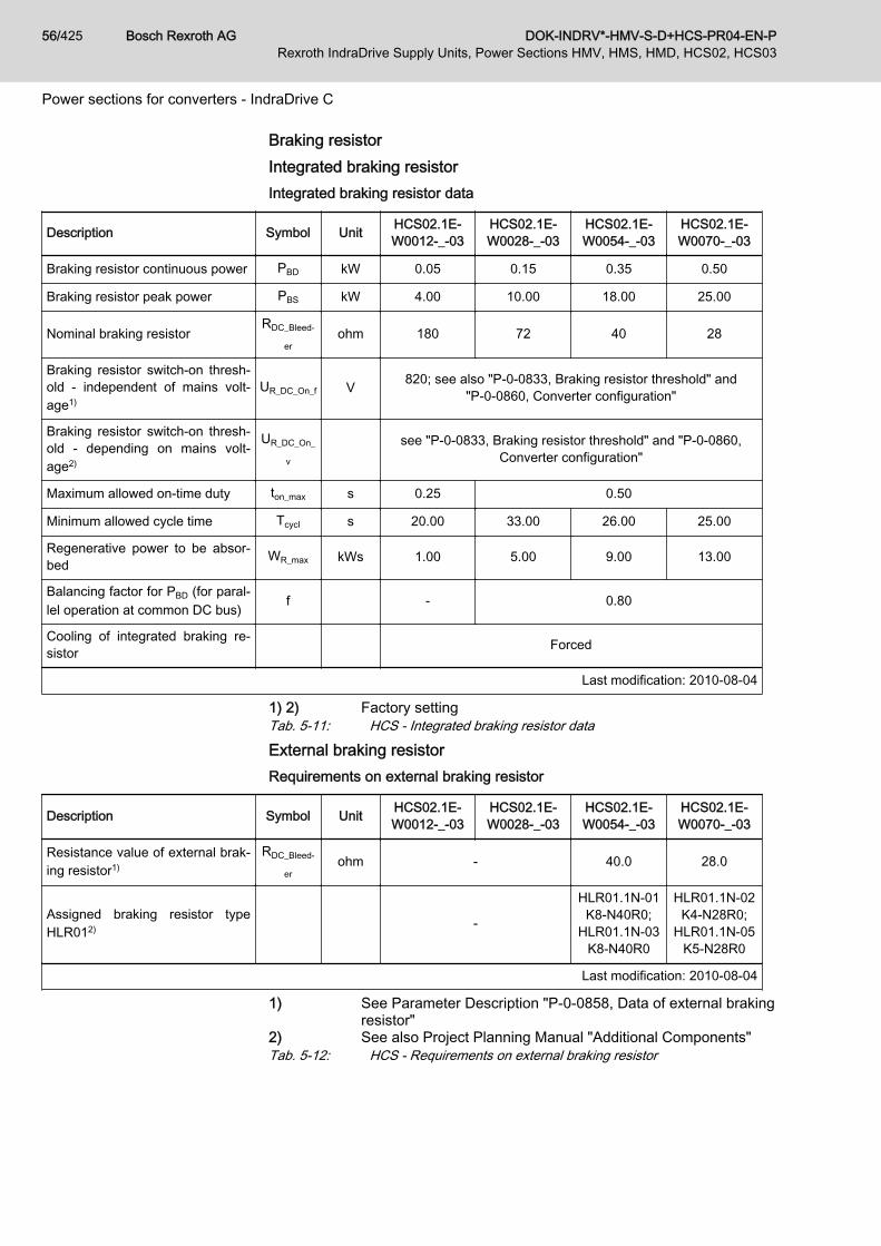
Braking resistorIntegrated braking resistorIntegrated braking resistor data
Description Symbol Unit HCS02.1E-W0012-_-03
HCS02.1E-W0028-_-03
HCS02.1E-W0054-_-03
HCS02.1E-W0070-_-03
Braking resistor continuous power PBD kW 0.05 0.15 0.35 0.50
Braking resistor peak power PBS kW 4.00 10.00 18.00 25.00
Nominal braking resistorRDC_Bleed‐
erohm 180 72 40 28
Braking resistor switch-on thresh‐old - independent of mains volt‐age1)
UR_DC_On_f V 820; see also "P-0-0833, Braking resistor threshold" and"P-0-0860, Converter configuration"
Braking resistor switch-on thresh‐old - depending on mains volt‐age2)
UR_DC_On_
v
see "P-0-0833, Braking resistor threshold" and "P-0-0860,Converter configuration"
Maximum allowed on-time duty ton_max s 0.25 0.50
Minimum allowed cycle time Tcycl s 20.00 33.00 26.00 25.00
Regenerative power to be absor‐bed WR_max kWs 1.00 5.00 9.00 13.00
Balancing factor for PBD (for paral‐lel operation at common DC bus) f - 0.80
Cooling of integrated braking re‐sistor Forced
Last modification: 2010-08-04
1) 2) Factory settingTab. 5-11: HCS - Integrated braking resistor data
External braking resistorRequirements on external braking resistor
Description Symbol Unit HCS02.1E-W0012-_-03
HCS02.1E-W0028-_-03
HCS02.1E-W0054-_-03
HCS02.1E-W0070-_-03
Resistance value of external brak‐ing resistor1)
RDC_Bleed‐
erohm - 40.0 28.0
Assigned braking resistor typeHLR012) -
HLR01.1N-01K8-N40R0;
HLR01.1N-03K8-N40R0
HLR01.1N-02K4-N28R0;
HLR01.1N-05K5-N28R0
Last modification: 2010-08-04
1) See Parameter Description "P-0-0858, Data of external brakingresistor"
2) See also Project Planning Manual "Additional Components"Tab. 5-12: HCS - Requirements on external braking resistor
Bosch Rexroth AG DOK-INDRV*-HMV-S-D+HCS-PR04-EN-P56/425Rexroth IndraDrive Supply Units, Power Sections HMV, HMS, HMD, HCS02, HCS03
Power sections for converters - IndraDrive C
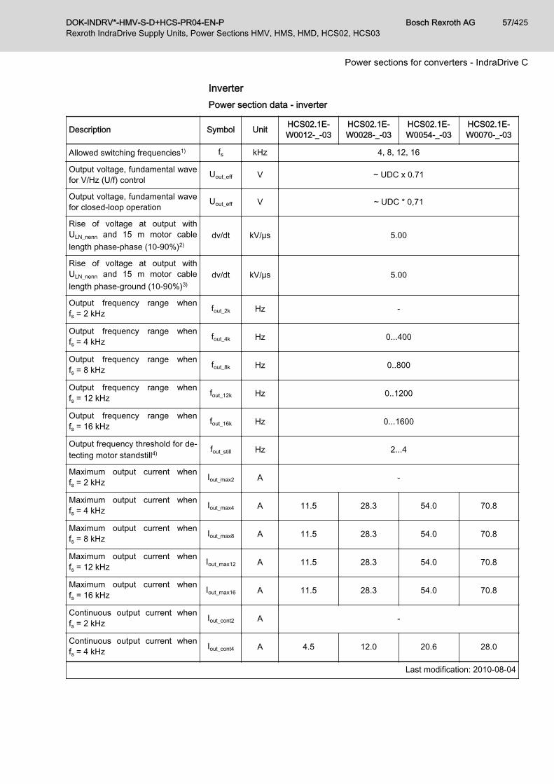
InverterPower section data - inverter
Description Symbol Unit HCS02.1E-W0012-_-03
HCS02.1E-W0028-_-03
HCS02.1E-W0054-_-03
HCS02.1E-W0070-_-03
Allowed switching frequencies1) fs kHz 4, 8, 12, 16
Output voltage, fundamental wavefor V/Hz (U/f) control Uout_eff V ~ UDC x 0.71
Output voltage, fundamental wavefor closed-loop operation Uout_eff V ~ UDC * 0,71
Rise of voltage at output withULN_nenn and 15 m motor cablelength phase-phase (10-90%)2)
dv/dt kV/µs 5.00
Rise of voltage at output withULN_nenn and 15 m motor cablelength phase-ground (10-90%)3)
dv/dt kV/µs 5.00
Output frequency range whenfs = 2 kHz fout_2k Hz -
Output frequency range whenfs = 4 kHz fout_4k Hz 0...400
Output frequency range whenfs = 8 kHz fout_8k Hz 0..800
Output frequency range whenfs = 12 kHz fout_12k Hz 0..1200
Output frequency range whenfs = 16 kHz fout_16k Hz 0...1600
Output frequency threshold for de‐tecting motor standstill4) fout_still Hz 2...4
Maximum output current whenfs = 2 kHz Iout_max2 A -
Maximum output current whenfs = 4 kHz Iout_max4 A 11.5 28.3 54.0 70.8
Maximum output current whenfs = 8 kHz Iout_max8 A 11.5 28.3 54.0 70.8
Maximum output current whenfs = 12 kHz Iout_max12 A 11.5 28.3 54.0 70.8
Maximum output current whenfs = 16 kHz Iout_max16 A 11.5 28.3 54.0 70.8
Continuous output current whenfs = 2 kHz Iout_cont2 A -
Continuous output current whenfs = 4 kHz Iout_cont4 A 4.5 12.0 20.6 28.0
Last modification: 2010-08-04
DOK-INDRV*-HMV-S-D+HCS-PR04-EN-P Bosch Rexroth AG 57/425Rexroth IndraDrive Supply Units, Power Sections HMV, HMS, HMD, HCS02, HCS03
Power sections for converters - IndraDrive C
Description Symbol Unit HCS02.1E-W0012-_-03
HCS02.1E-W0028-_-03
HCS02.1E-W0054-_-03
HCS02.1E-W0070-_-03
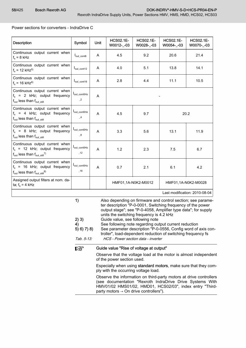
Continuous output current whenfs = 8 kHz Iout_cont8 A 4.5 9.2 20.6 21.4
Continuous output current whenfs = 12 kHz5) Iout_cont12 A 4.0 5.1 13.8 14.1
Continuous output current whenfs = 16 kHz6) Iout_cont16 A 2.8 4.4 11.1 10.5
Continuous output current whenfs = 2 kHz; output frequencyfout less than fout_still
Iout_cont0Hz
_2A -
Continuous output current whenfs = 4 kHz; output frequencyfout less than fout_still
Iout_cont0Hz
_4A 4.5 9.7 20.2
Continuous output current whenfs = 8 kHz; output frequencyfout less than fout_still
Iout_cont0Hz
_8A 3.3 5.6 13.1 11.9
Continuous output current whenfs = 12 kHz; output frequencyfout less than fout_still
7)
Iout_cont0Hz
_12A 1.2 2.3 7.5 6.7
Continuous output current whenfs = 16 kHz; output frequencyfout less than fout_still
8)
Iout_cont0Hz
_16A 0.7 2.1 6.1 4.2
Assigned output filters at nom. da‐ta; fs = 4 kHz HMF01,1A-N0K2-M0012 HMF01,1A-N0K2-M0028
Last modification: 2010-08-04
1) Also depending on firmware and control section; see parame‐ter description "P-0-0001, Switching frequency of the poweroutput stage"; see "P-0-4058, Amplifier type data"; for supplyunits the switching frequency is 4.2 kHz
2) 3) Guide value, see following note4) See following note regarding output current reduction5) 6) 7) 8) See parameter description "P-0-0556, Config word of axis con‐
troller", load-dependent reduction of switching frequency fsTab. 5-13: HCS - Power section data - inverter
Guide value "Rise of voltage at output"Observe that the voltage load at the motor is almost independentof the power section used.Especially when using standard motors, make sure that they com‐ply with the occurring voltage load.Observe the information on third-party motors at drive controllers(see documentation "Rexroth IndraDrive Drive Systems WithHMV01/02 HMS01/02, HMD01, HCS02/03", index entry "Third-party motors → On drive controllers").
Bosch Rexroth AG DOK-INDRV*-HMV-S-D+HCS-PR04-EN-P58/425Rexroth IndraDrive Supply Units, Power Sections HMV, HMS, HMD, HCS02, HCS03
Power sections for converters - IndraDrive C

Reduced output current at motor standstillDepending on the electric output frequency, the output current isreduced for thermal protection of the power section.The output current is reduced, when the electric output frequencyhas fallen below the threshold to detect motor standstill.
Exemplary data for applicationsGeneral informationThis section contains● Examples of allowed current profiles● Examples of allowed performance profiles● Data for selecting standard motors
Current profilesExamples of allowed current profiles
Description Symbol Unit HCS02.1E-W0012-_-03
HCS02.1E-W0028-_-03
HCS02.1E-W0054-_-03
HCS02.1E-W0070-_-03
Maximum output current atIout_base_1; fs = 2 kHz; t = 0.4 s;T = 4 s; K = 2.51)
Iout_peak1_2 A -
Base load current at Iout_peak_1;fs = 2 kHz; t = 0.4 s; T = 4 s;K = 2.5
Iout_base1_2 A -
Maximum output current atIout_base_1; fs = 4 kHz; t = 0,4 s;T = 4 s; K = 2,52)
Iout_peak1_4 A 9.07 24.29 41.66 56.56
Base load current at Iout_peak_1;fs = 4 kHz; t = 0,4 s; T = 4 s;K = 2,5
Iout_base1_4 A 3.63 9.72 16.66 22.62
Maximum output current atIout_base_1; fs = 8 kHz; t = 0.4 s;T = 4 s; K = 2.53)
Iout_peak1_8 A 9.07 15.06 33.59 34.77
Base load current at Iout_peak_1;fs = 8 kHz; t = 0.4 s; T = 4 s;K = 2.5
Iout_base1_8 A 3.63 6.02 13.43 13.91
Maximum output current atIout_base_1; fs = 12 kHz; t = 0.4 s;T = 4 s; K = 2.54)
Iout_peak1_1
2A 6.03 8.42 21.96 23.12
Base load current at Iout_peak_1;fs = 12 kHz; t = 0.4 s; T = 4 s;K = 2.5
Iout_base1_1
2A 2.41 3.37 8.78 9.25
Maximum output current atIout_base_1; fs = 16 kHz; t = 0.4 s;T = 4 s; K = 2.55)
Iout_peak1_1
6A 4.25 7.29 17.77 17.16
Last modification: 2010-08-04
DOK-INDRV*-HMV-S-D+HCS-PR04-EN-P Bosch Rexroth AG 59/425Rexroth IndraDrive Supply Units, Power Sections HMV, HMS, HMD, HCS02, HCS03
Power sections for converters - IndraDrive C

Description Symbol Unit HCS02.1E-W0012-_-03
HCS02.1E-W0028-_-03
HCS02.1E-W0054-_-03
HCS02.1E-W0070-_-03
Base load current at Iout_peak_1;fs = 16 kHz; t = 0.4 s; T = 4 s;K = 2.5
Iout_base1_1
6A 1.70 2.92 7.11 6.86
Maximum output current atIout_base_3; fs = 2 kHz; t = 2 s;T = 20 s; K = 2.06)
Iout_peak3_2 A -
Base load current at Iout_peak_3;fs = 2 kHz; t = 2 s; T = 20 s;K = 2.0
Iout_base3_2 A -
Maximum output current atIout_base_3; fs = 4 kHz; t = 2 s;T = 20 s; K = 2,07)
Iout_peak3_4 A 7.79 20.90 35.86 48.68
Base load current at Iout_peak_3;fs = 4 kHz; t = 2 s; T = 20 s;K = 2,0
Iout_base3_4 A 3.90 10.45 17.93 24.34
Maximum output current atIout_base_3; fs = 8 kHz; t = 2 s;T = 20 s; K = 2.08)
Iout_peak3_8 A 7.79 13.55 30.54 31.36
Base load current at Iout_peak_3;fs = 8 kHz; t = 2 s; T = 20 s;K = 2.0
Iout_base3_8 A 3.90 6.77 15.27 15.68
Maximum output current atIout_base_3; fs = 12 kHz; t = 2 s;T = 20 s; K = 2.09)
Iout_peak3_1
2A 5.57 7.56 19.88 20.81
Base load current at Iout_peak_3;fs = 12 kHz; t = 2 s; T = 20 s;K = 2.0
Iout_base3_1
2A 2.78 3.78 9.94 10.40
Maximum output current atIout_base_3; fs = 16 kHz; t = 2 s;T = 20 min; K = 2.010)
Iout_peak3_1
6A 3.90 6.55 16.06 15.42
Base load current at Iout_peak_3;fs = 16 kHz; t = 2 s; T = 20 s;K = 2.0
Iout_base3_1
6A 1.95 3.27 8.03 7.71
Base load current at Iout_peak_4;fs = 2 kHz; t = 60 s; T = 5 min;K = 1.5
Iout_base4_2 A -
Maximum output current atIout_base_4; fs = 2 kHz; t = 60 s;T = 5 min; K = 1.511)
Iout_peak4_2 A -
Maximum output current atIout_base_4; fs = 4 kHz; t = 60 s;T = 5 min; K = 1,512)
Iout_peak4_4 A 5.22 14.79 25.13 33.74
Last modification: 2010-08-04
Bosch Rexroth AG DOK-INDRV*-HMV-S-D+HCS-PR04-EN-P60/425Rexroth IndraDrive Supply Units, Power Sections HMV, HMS, HMD, HCS02, HCS03
Power sections for converters - IndraDrive C
Description Symbol Unit HCS02.1E-W0012-_-03
HCS02.1E-W0028-_-03
HCS02.1E-W0054-_-03
HCS02.1E-W0070-_-03
Base load current at Iout_peak_4;fs = 4 kHz; t = 60 s; T = 5 min;K = 1,5
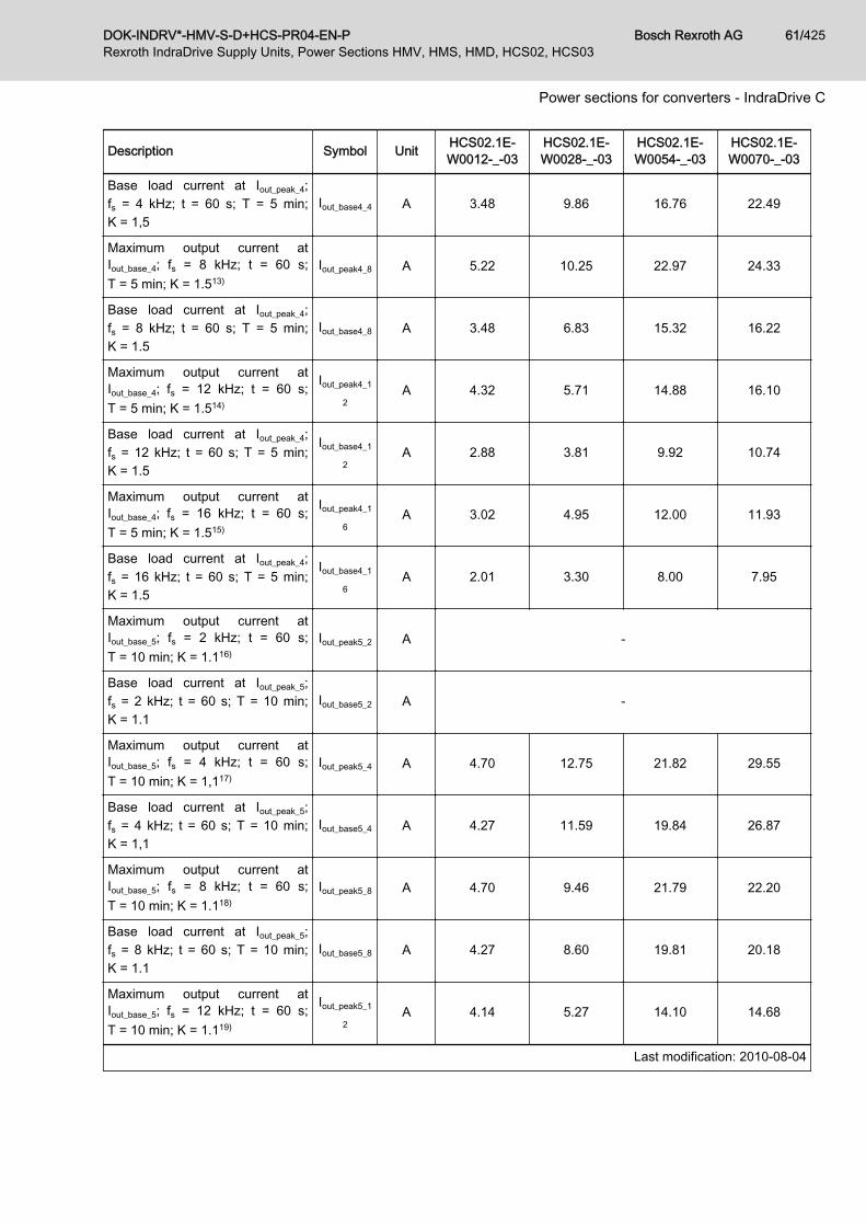
Iout_base4_4 A 3.48 9.86 16.76 22.49
Maximum output current atIout_base_4; fs = 8 kHz; t = 60 s;T = 5 min; K = 1.513)
Iout_peak4_8 A 5.22 10.25 22.97 24.33
Base load current at Iout_peak_4;fs = 8 kHz; t = 60 s; T = 5 min;K = 1.5
Iout_base4_8 A 3.48 6.83 15.32 16.22
Maximum output current atIout_base_4; fs = 12 kHz; t = 60 s;T = 5 min; K = 1.514)
Iout_peak4_1
2A 4.32 5.71 14.88 16.10
Base load current at Iout_peak_4;fs = 12 kHz; t = 60 s; T = 5 min;K = 1.5
Iout_base4_1
2A 2.88 3.81 9.92 10.74
Maximum output current atIout_base_4; fs = 16 kHz; t = 60 s;T = 5 min; K = 1.515)
Iout_peak4_1
6A 3.02 4.95 12.00 11.93
Base load current at Iout_peak_4;fs = 16 kHz; t = 60 s; T = 5 min;K = 1.5
Iout_base4_1
6A 2.01 3.30 8.00 7.95
Maximum output current atIout_base_5; fs = 2 kHz; t = 60 s;T = 10 min; K = 1.116)
Iout_peak5_2 A -
Base load current at Iout_peak_5;fs = 2 kHz; t = 60 s; T = 10 min;K = 1.1
Iout_base5_2 A -
Maximum output current atIout_base_5; fs = 4 kHz; t = 60 s;T = 10 min; K = 1,117)
Iout_peak5_4 A 4.70 12.75 21.82 29.55
Base load current at Iout_peak_5;fs = 4 kHz; t = 60 s; T = 10 min;K = 1,1
Iout_base5_4 A 4.27 11.59 19.84 26.87
Maximum output current atIout_base_5; fs = 8 kHz; t = 60 s;T = 10 min; K = 1.118)
Iout_peak5_8 A 4.70 9.46 21.79 22.20
Base load current at Iout_peak_5;fs = 8 kHz; t = 60 s; T = 10 min;K = 1.1
Iout_base5_8 A 4.27 8.60 19.81 20.18
Maximum output current atIout_base_5; fs = 12 kHz; t = 60 s;T = 10 min; K = 1.119)
Iout_peak5_1
2A 4.14 5.27 14.10 14.68
Last modification: 2010-08-04
DOK-INDRV*-HMV-S-D+HCS-PR04-EN-P Bosch Rexroth AG 61/425Rexroth IndraDrive Supply Units, Power Sections HMV, HMS, HMD, HCS02, HCS03
Power sections for converters - IndraDrive C

Description Symbol Unit HCS02.1E-W0012-_-03
HCS02.1E-W0028-_-03
HCS02.1E-W0054-_-03
HCS02.1E-W0070-_-03
Base load current at Iout_peak_5;fs = 12 kHz; t = 60 s; T = 10 min;K = 1.1
Iout_base5_1
2A 3.76 4.79 12.82 13.35
Maximum output current atIout_base_5; fs = 16 kHz; t = 60 s;T = 10 min; K = 1.120)
Iout_peak5_1
6A 2.89 4.57 11.37 10.87
Base load current at Iout_peak_5;fs = 16 kHz; t = 60 s; T = 10 min;K = 1.1
Iout_base5_1
6A 2.63 4.15 10.33 9.88
Last modification: 2010-08-04
1) 2) 3) 4) 5) 6) 7) 8) 9) 10) 11) 12) 13) 14) 15) 16) 17) 18) 19) 20) See defi‐nition pro‐fileUEL_I_e
Tab. 5-14: HCS - Examples of allowed current profilesCurrent profile "UEL_I_e" The following current profiles have been defined for converters and inverters.
Profile Explanation
current profile "UEL_I_e" The characteristic data of the profile are used toselect converters and inverters for operationwith standard motors and servo drives.
Tab. 5-15: Definition of current profiles
Bosch Rexroth AG DOK-INDRV*-HMV-S-D+HCS-PR04-EN-P62/425Rexroth IndraDrive Supply Units, Power Sections HMV, HMS, HMD, HCS02, HCS03
Power sections for converters - IndraDrive C

Performance profilesExamples of allowed performance profiles
Description Symbol Unit HCS02.1E-W0012-_-03
HCS02.1E-W0028-_-03
HCS02.1E-W0054-_-03
HCS02.1E-W0070-_-03
maximum DC bus power atULN_nenn; Ta ≤ Ta_work; t = 0.4 s;T = 4 s; K = 2.5;PDC_peak = PDC_max; without mainschoke1)
PDC_peak_1 kW 4.25 10.33 14.17 18.19
maximum DC bus power atULN_nenn; Ta ≤ Ta_work; t = 0.4 s;T = 4 s; K = 2.5;PDC_peak = PDC_max; with mainschoke2)
PDC_peak_1 kW - 20.24 28.30
DC bus power at ULN_nenn;Ta ≤ Ta_work; t =0.4 s; T = 4 s;K = 2.5; PDC_peak = PDC_max; withoutmains choke3)
PDC_base_1 kW 1.68 4.12 5.67 7.26
DC bus power at ULN_nenn;Ta ≤ Ta_work; t = 0.4 s; T = 4 s;K = 2.5; PDC_peak = PDC_max; withmains choke4)
PDC_base_1 kW - 8.11 11.30
maximum DC bus power atULN_nenn; Ta ≤ Ta_work; t = 2 s;T = 20 s; K = 2.0; without mainschoke5)
PDC_peak_3 kW 3.64 8.88 12.19 15.65
maximum DC bus power atULN_nenn; Ta ≤ Ta_work; t = 2 s;T = 20 s; K = 2.0; with mainschoke6)
PDC_peak_3 kW - 17.41 24.34
DC bus power at ULN_nenn;Ta ≤ Ta_work; t = 2 s; T = 20 s;K = 2.0; without mains choke7)
PDC_base_3 kW 1.82 4.44 6.09 7.82
DC bus power at ULN_nenn;Ta ≤ Ta_work; t = 2 s; T = 20 s;K = 2.0; with mains choke8)
PDC_base_3 kW - 8.70 12.17
maximum DC bus power at beiULN_nenn; Ta ≤ Ta_work; t = 60 s;T = 5 min; K = 1.5; without mainschoke9)
PDC_peak_4 kW 2.44 6.29 8.54 10.85
DC bus power at ULN_nenn;Ta ≤ Ta_work; t = 60 s; T = 5 min;K = 1.5; with mains choke10)
PDC_peak_4 kW - 12.20 16.87
Last modification: 2010-08-04
DOK-INDRV*-HMV-S-D+HCS-PR04-EN-P Bosch Rexroth AG 63/425Rexroth IndraDrive Supply Units, Power Sections HMV, HMS, HMD, HCS02, HCS03
Power sections for converters - IndraDrive C
Description Symbol Unit HCS02.1E-W0012-_-03
HCS02.1E-W0028-_-03
HCS02.1E-W0054-_-03
HCS02.1E-W0070-_-03
DC bus power at ULN_nenn;Ta ≤ Ta_work; t = 60 s; T = 5 min;K = 1.5; without mains choke11)
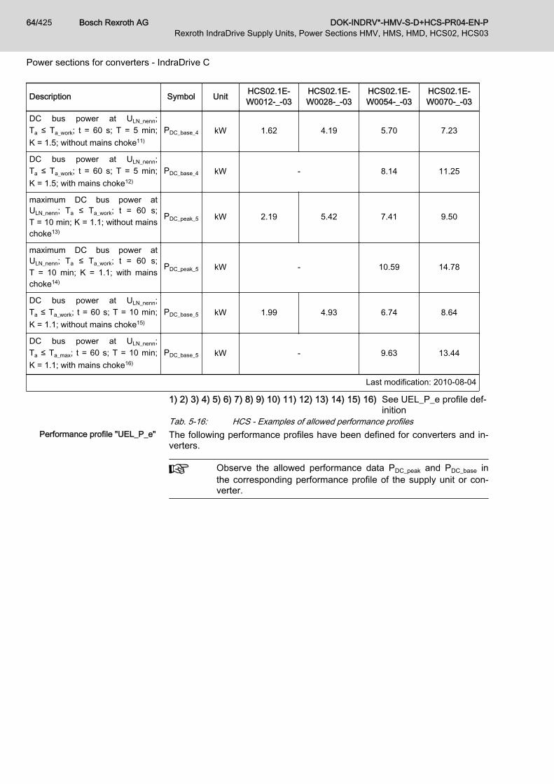
PDC_base_4 kW 1.62 4.19 5.70 7.23
DC bus power at ULN_nenn;Ta ≤ Ta_work; t = 60 s; T = 5 min;K = 1.5; with mains choke12)
PDC_base_4 kW - 8.14 11.25
maximum DC bus power atULN_nenn; Ta ≤ Ta_work; t = 60 s;T = 10 min; K = 1.1; without mainschoke13)
PDC_peak_5 kW 2.19 5.42 7.41 9.50
maximum DC bus power atULN_nenn; Ta ≤ Ta_work; t = 60 s;T = 10 min; K = 1.1; with mainschoke14)
PDC_peak_5 kW - 10.59 14.78
DC bus power at ULN_nenn;Ta ≤ Ta_work; t = 60 s; T = 10 min;K = 1.1; without mains choke15)
PDC_base_5 kW 1.99 4.93 6.74 8.64
DC bus power at ULN_nenn;Ta ≤ Ta_max; t = 60 s; T = 10 min;K = 1.1; with mains choke16)
PDC_base_5 kW - 9.63 13.44
Last modification: 2010-08-04
1) 2) 3) 4) 5) 6) 7) 8) 9) 10) 11) 12) 13) 14) 15) 16) See UEL_P_e profile def‐inition
Tab. 5-16: HCS - Examples of allowed performance profilesPerformance profile "UEL_P_e" The following performance profiles have been defined for converters and in‐
verters.
Observe the allowed performance data PDC_peak and PDC_base inthe corresponding performance profile of the supply unit or con‐verter.
Bosch Rexroth AG DOK-INDRV*-HMV-S-D+HCS-PR04-EN-P64/425Rexroth IndraDrive Supply Units, Power Sections HMV, HMS, HMD, HCS02, HCS03
Power sections for converters - IndraDrive C

Profile Explanation
Performance profile "UEL_P_e" Characteristic of the selection of standard mo‐tors and servo drives.
Tab. 5-17: Definition of Performance Profiles, Infeeding Supply Units and Con‐verters
Operation with standard motorsGeneral information
Selecting standard motors The tables below show the nominal powers Pnenn of standard motors whichcan be operated at the respective drive controller. The following conditionsapply to the data in the tables:● Motor design:
4-pole standard motor (2 pole pairs) with rated voltage 3 AC 400 V,50 Hz at mains voltage ULN ≥ 3 AC 400 V or4-pole standard motor (2 pole pairs) with rated voltage 3 AC 460 V,60 Hz at mains voltage ULN ≥ 3 AC 460 V
● Assigned mains choke is used● Operation at minimum switching frequency fs= fs (min.)● Rotary field at output with fout>fout_still
● Ambient temperature Ta≤Ta_work
● Overload ratio K = PDC_peak / PDC_base according to performance profile"UEL_P_e"
● Type of mains connection: Individual Supply
When choosing standard motors for inverters, select an appropri‐ate supply unit. Observe the performance data PDC_peak andPDC_base in the performance profile "UEL_P_e" of the supply unit.
DOK-INDRV*-HMV-S-D+HCS-PR04-EN-P Bosch Rexroth AG 65/425Rexroth IndraDrive Supply Units, Power Sections HMV, HMS, HMD, HCS02, HCS03
Power sections for converters - IndraDrive C
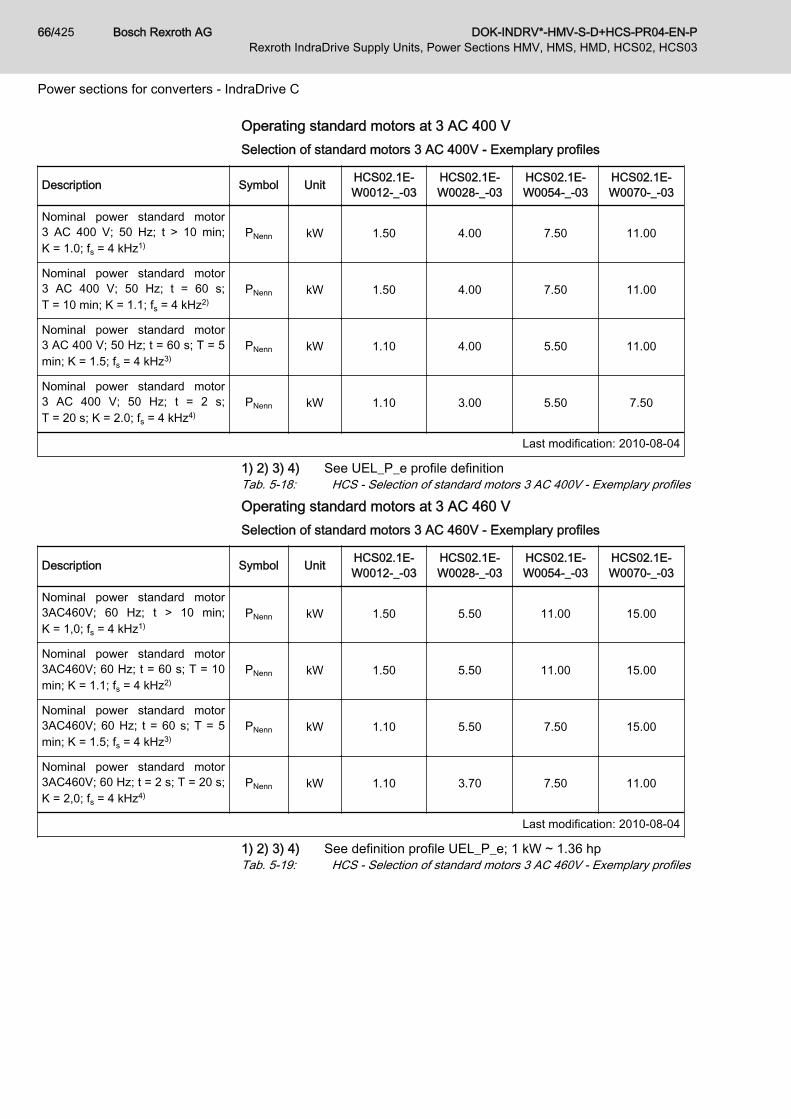
Operating standard motors at 3 AC 400 VSelection of standard motors 3 AC 400V - Exemplary profiles
Description Symbol Unit HCS02.1E-W0012-_-03
HCS02.1E-W0028-_-03
HCS02.1E-W0054-_-03
HCS02.1E-W0070-_-03
Nominal power standard motor3 AC 400 V; 50 Hz; t > 10 min;K = 1.0; fs = 4 kHz1)
PNenn kW 1.50 4.00 7.50 11.00
Nominal power standard motor3 AC 400 V; 50 Hz; t = 60 s;T = 10 min; K = 1.1; fs = 4 kHz2)
PNenn kW 1.50 4.00 7.50 11.00
Nominal power standard motor3 AC 400 V; 50 Hz; t = 60 s; T = 5min; K = 1.5; fs = 4 kHz3)
PNenn kW 1.10 4.00 5.50 11.00
Nominal power standard motor3 AC 400 V; 50 Hz; t = 2 s;T = 20 s; K = 2.0; fs = 4 kHz4)
PNenn kW 1.10 3.00 5.50 7.50
Last modification: 2010-08-04
1) 2) 3) 4) See UEL_P_e profile definitionTab. 5-18: HCS - Selection of standard motors 3 AC 400V - Exemplary profiles
Operating standard motors at 3 AC 460 VSelection of standard motors 3 AC 460V - Exemplary profiles
Description Symbol Unit HCS02.1E-W0012-_-03
HCS02.1E-W0028-_-03
HCS02.1E-W0054-_-03
HCS02.1E-W0070-_-03
Nominal power standard motor3AC460V; 60 Hz; t > 10 min;K = 1,0; fs = 4 kHz1)
PNenn kW 1.50 5.50 11.00 15.00
Nominal power standard motor3AC460V; 60 Hz; t = 60 s; T = 10min; K = 1.1; fs = 4 kHz2)
PNenn kW 1.50 5.50 11.00 15.00
Nominal power standard motor3AC460V; 60 Hz; t = 60 s; T = 5min; K = 1.5; fs = 4 kHz3)
PNenn kW 1.10 5.50 7.50 15.00
Nominal power standard motor3AC460V; 60 Hz; t = 2 s; T = 20 s;K = 2,0; fs = 4 kHz4)
PNenn kW 1.10 3.70 7.50 11.00
Last modification: 2010-08-04
1) 2) 3) 4) See definition profile UEL_P_e; 1 kW ~ 1.36 hpTab. 5-19: HCS - Selection of standard motors 3 AC 460V - Exemplary profiles
Bosch Rexroth AG DOK-INDRV*-HMV-S-D+HCS-PR04-EN-P66/425Rexroth IndraDrive Supply Units, Power Sections HMV, HMS, HMD, HCS02, HCS03
Power sections for converters - IndraDrive C

5.2.5 Connections and interfacesOverview
Overall connection diagram
X1, L+/L- Not available for HCS02.1E-W0012
DOK-INDRV*-HMV-S-D+HCS-PR04-EN-P Bosch Rexroth AG 67/425Rexroth IndraDrive Supply Units, Power Sections HMV, HMS, HMD, HCS02, HCS03
Power sections for converters - IndraDrive C
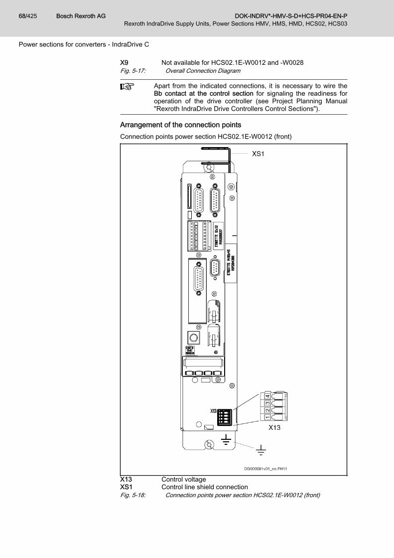
X9 Not available for HCS02.1E-W0012 and -W0028Fig. 5-17: Overall Connection Diagram
Apart from the indicated connections, it is necessary to wire theBb contact at the control section for signaling the readiness foroperation of the drive controller (see Project Planning Manual"Rexroth IndraDrive Drive Controllers Control Sections").
Arrangement of the connection pointsConnection points power section HCS02.1E-W0012 (front)
X13 Control voltageXS1 Control line shield connectionFig. 5-18: Connection points power section HCS02.1E-W0012 (front)
Bosch Rexroth AG DOK-INDRV*-HMV-S-D+HCS-PR04-EN-P68/425Rexroth IndraDrive Supply Units, Power Sections HMV, HMS, HMD, HCS02, HCS03
Power sections for converters - IndraDrive C

Connection points power section HCS02.1E-W0012 (bottom)
X3 Mains connectionX5 Motor connectionX6 Motor temperature monitoring, motor holding brakeXS2 Motor cable shield connectionFig. 5-19: Connection points power section HCS02.1E-W0012 (bottom)
DOK-INDRV*-HMV-S-D+HCS-PR04-EN-P Bosch Rexroth AG 69/425Rexroth IndraDrive Supply Units, Power Sections HMV, HMS, HMD, HCS02, HCS03
Power sections for converters - IndraDrive C

Connection points power sections HCS02.1E-W0028, -W0054, ‑W0070(front)
X1 Module busX13 Control voltageXS1 Control line shield connectionL+, L- DC busFig. 5-20: Connection points power sections HCS02.1E-W0028, -W0054,
‑W0070 (front)
Bosch Rexroth AG DOK-INDRV*-HMV-S-D+HCS-PR04-EN-P70/425Rexroth IndraDrive Supply Units, Power Sections HMV, HMS, HMD, HCS02, HCS03
Power sections for converters - IndraDrive C

Connection points power section HCS02.1E-W0028 (bottom)
X3 Mains connectionX5 Motor connectionX6 Motor temperature monitoring, motor holding brakeXS2 Motor cable shield connectionFig. 5-21: Connection points power section HCS02.1E-W0028 (bottom)
DOK-INDRV*-HMV-S-D+HCS-PR04-EN-P Bosch Rexroth AG 71/425Rexroth IndraDrive Supply Units, Power Sections HMV, HMS, HMD, HCS02, HCS03
Power sections for converters - IndraDrive C
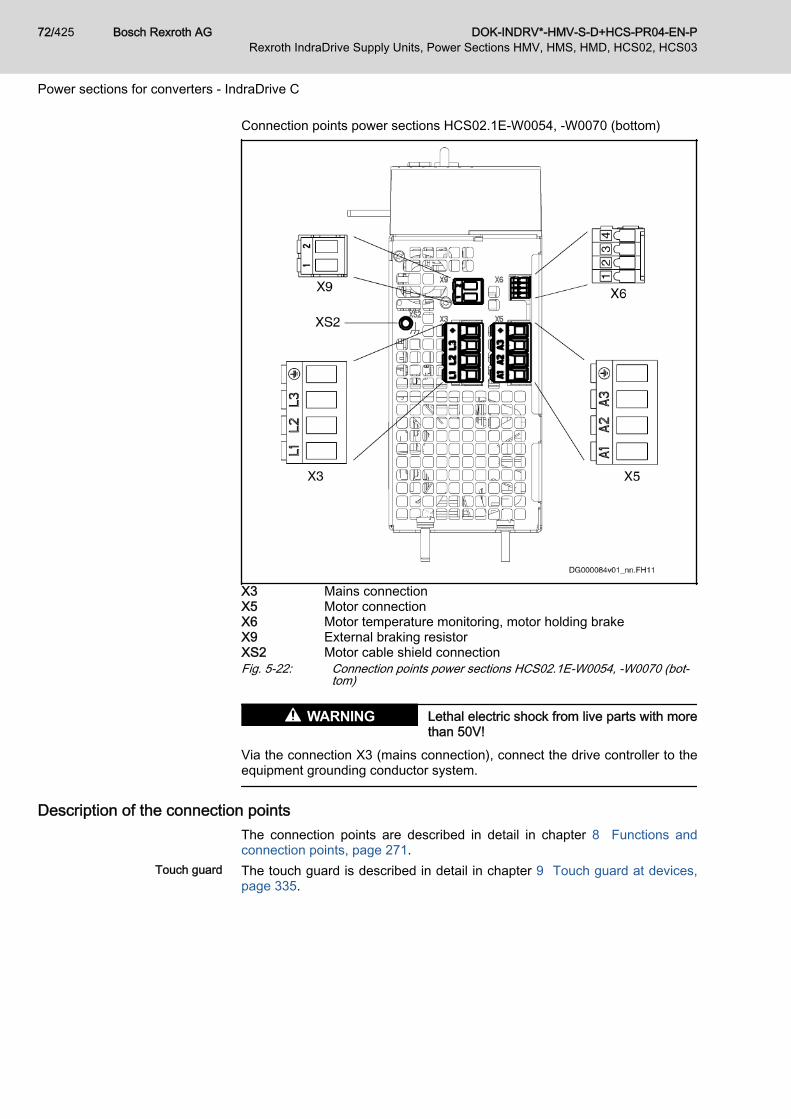
Connection points power sections HCS02.1E-W0054, ‑W0070 (bottom)
X3 Mains connectionX5 Motor connectionX6 Motor temperature monitoring, motor holding brakeX9 External braking resistorXS2 Motor cable shield connectionFig. 5-22: Connection points power sections HCS02.1E-W0054, -W0070 (bot‐
tom)
Lethal electric shock from live parts with morethan 50V!
WARNING
Via the connection X3 (mains connection), connect the drive controller to theequipment grounding conductor system.
Description of the connection pointsThe connection points are described in detail in chapter 8 Functions andconnection points, page 271.
Touch guard The touch guard is described in detail in chapter 9 Touch guard at devices,page 335.
Bosch Rexroth AG DOK-INDRV*-HMV-S-D+HCS-PR04-EN-P72/425Rexroth IndraDrive Supply Units, Power Sections HMV, HMS, HMD, HCS02, HCS03
Power sections for converters - IndraDrive C