Embed Size (px)
Citation preview
Project Planning Manual
Electric Drivesand Controls Pneumatics Service
Linear Motion and Assembly TechnologiesHydraulics
Rexroth IndraDrive CsDrive Systems with HCS01
R911322210Edition 02
Rexroth IndraDrive CsDrive Systems with HCS01
Project Planning Manual
DOK-INDRV*-HCS01******-PR02-EN-P
RS-898e3e765ff4d61d0a6846a000329fdd-3-en-US-2
● Overview information of the Rexroth IndraDrive Cs drive system● Description of the allowed combinations of Rexroth IndraDrive Cs sys‐
tem components● Selection of the system components of the Rexroth IndraDrive Cs drive
system● Specification applying to all components (ambient and operating condi‐
tions)● Application description of system characteristics
Edition Release Date Notes
DOK-INDRV*-HCS01******-PR01-EN-P 2009/08 -DOK-INDRV*-HCS01******-PR02-EN-P 2012/07 See index entry "Docu‐
mentation → Editions"
Copyright © Bosch Rexroth AG 2012This document, as well as the data, specifications and other information setforth in it, are the exclusive property of Bosch Rexroth AG. It may not be re‐produced or given to third parties without its consent.
Liability The specified data is intended for product description purposes only and shallnot be deemed to be a guaranteed characteristic unless expressly stipulatedin the contract. All rights are reserved with respect to the content of this docu‐mentation and the availability of the product.
Published by Bosch Rexroth AGBgm.-Dr.-Nebel-Str. 2 ■ 97816 Lohr a. Main, GermanyPhone +49 9352 18 0 ■ Fax +49 9352 18 8400http://www.boschrexroth.com/Dept. DC-IA/EDY (MW), DC-IA/EDY1 (RB/US/BB), DC-IA/EDY2 (CG, MR),DC-IA/EDY4 (CR)
Title
Type of Documentation
Document Typecode
Internal File Reference
Purpose of Documentation
Record of Revision
Bosch Rexroth AG DOK-INDRV*-HCS01******-PR02-EN-P Rexroth IndraDrive Cs Drive Systems with HCS01
Table of ContentsPage
1 System Presentation...................................................................................................... 71.1 Drive Range Rexroth IndraDrive Cs....................................................................................................... 71.1.1 Overview – Rexroth IndraDrive Cs...................................................................................................... 71.1.2 Target Applications.............................................................................................................................. 81.1.3 Features.............................................................................................................................................. 9
Functional Features.......................................................................................................................... 9Performance Features.................................................................................................................... 11Combination of HCS01 and MSM/MSK.......................................................................................... 12Interfaces........................................................................................................................................ 12Supported Encoder Systems.......................................................................................................... 12
1.2 System Configuration........................................................................................................................... 141.2.1 System Structure............................................................................................................................... 141.2.2 Components of the System............................................................................................................... 15
Drive Controllers HCS01................................................................................................................ 15Control Panel HAP01..................................................................................................................... 16Firmware......................................................................................................................................... 17
1.2.3 About This Documentation................................................................................................................ 18Purpose.......................................................................................................................................... 18Editions........................................................................................................................................... 19Documentations.............................................................................................................................. 20Your Feedback............................................................................................................................... 21
2 Important Directions for Use ....................................................................................... 232.1 Appropriate Use ................................................................................................................................... 232.1.1 Introduction........................................................................................................................................ 232.1.2 Areas of Use and Application............................................................................................................ 232.2 Inappropriate Use................................................................................................................................. 24
3 Safety Instructions for Electric Drives and Controls..................................................... 253.1 Definitions of Terms.............................................................................................................................. 253.2 General Information.............................................................................................................................. 263.2.1 Using the Safety Instructions and Passing Them on to Others......................................................... 263.2.2 Requirements for Safe Use............................................................................................................... 263.2.3 Hazards by Improper Use.................................................................................................................. 273.3 Instructions with Regard to Specific Dangers....................................................................................... 283.3.1 Protection Against Contact With Electrical Parts and Housings........................................................ 283.3.2 Protective Extra-Low Voltage as Protection Against Electric Shock ................................................ 293.3.3 Protection Against Dangerous Movements....................................................................................... 303.3.4 Protection Against Magnetic and Electromagnetic Fields During Operation and Mounting.............. 313.3.5 Protection Against Contact With Hot Parts........................................................................................ 323.3.6 Protection During Handling and Mounting......................................................................................... 323.3.7 Battery Safety.................................................................................................................................... 323.3.8 Protection Against Pressurized Systems........................................................................................... 33
DOK-INDRV*-HCS01******-PR02-EN-P Rexroth IndraDrive Cs Drive Systems with HCS01
Bosch Rexroth AG I/271
Table of Contents
Page
3.4 Explanation of Signal Words and the Safety Alert Symbol................................................................... 33
4 Combining the Individual Components........................................................................ 354.1 Documentations.................................................................................................................................... 354.2 Brief Description of the Individual Components.................................................................................... 354.2.1 HCS01 - Brief Description and Design.............................................................................................. 354.3 Configuring the Drive System............................................................................................................... 354.3.1 Converter........................................................................................................................................... 354.3.2 Functional Equipment........................................................................................................................ 374.3.3 Firmware............................................................................................................................................ 38
Firmware and Device Types........................................................................................................... 38Firmware-Types.............................................................................................................................. 38Firmware Variants.......................................................................................................................... 39
4.3.4 Motors................................................................................................................................................ 39IndraDyn......................................................................................................................................... 39Third-Party Motors.......................................................................................................................... 40
4.3.5 Cables............................................................................................................................................... 45Motor Power Cables....................................................................................................................... 45Encoder Cables.............................................................................................................................. 46
4.4 Installation Conditions........................................................................................................................... 474.4.1 Ambient and Operating Conditions.................................................................................................... 474.4.2 Control Cabinet Design and Cooling................................................................................................. 494.4.3 UL Ratings......................................................................................................................................... 504.4.4 Compatibility With Foreign Matters.................................................................................................... 514.5 Mechanical Project Planning................................................................................................................ 514.5.1 Drive Controller.................................................................................................................................. 51
Dimensional Drawings.................................................................................................................... 51Dimensions, Mass, Insulation, Sound Pressure Level................................................................... 55Temperatures, Cooling, Power Dissipation, Distances.................................................................. 56Mounting Positions of Components................................................................................................ 58
4.6 Electrical Project Planning.................................................................................................................... 604.6.1 Overall Connection Diagram............................................................................................................. 604.6.2 Project Planning of Control Voltage................................................................................................... 60
Control Voltage for Drive Systems................................................................................................. 60Sizing the Control Voltage Supply.................................................................................................. 61
4.6.3 Mains Connection ............................................................................................................................. 66Residual-Current-Operated Circuit Breakers (RCD, RCCB) as Additional Fusing......................... 66Mains Types................................................................................................................................... 69Type of Mains Connection.............................................................................................................. 72Mains Connected Load and Mains Current ................................................................................... 76Dimensioning the Line Cross Sections and Fuses ........................................................................ 77Dimensioning and Selecting the Mains Transformer...................................................................... 83Dimensioning the Mains Filter........................................................................................................ 84Selecting the Mains Filter............................................................................................................... 86Determining the Mains Choke........................................................................................................ 90Dimensioning the Mains Contactor................................................................................................. 90
Bosch Rexroth AG DOK-INDRV*-HCS01******-PR02-EN-P Rexroth IndraDrive Cs Drive Systems with HCS01
II/271
Table of Contents
Page
Combining Transformer, Mains Filter and Mains Choke................................................................ 91Control Circuit for the Mains Connection........................................................................................ 92
4.6.4 DC Bus Coupling............................................................................................................................... 93Requirements for DC Bus Coupling............................................................................................... 93Central Supply and DC Bus Coupling............................................................................................ 93Group Supply and DC Bus Coupling.............................................................................................. 94Implementation of DC Bus Coupling.............................................................................................. 96DC Bus Capacitor Unit................................................................................................................... 99Module Bus and Parameterization............................................................................................... 100Bb Relay Contact.......................................................................................................................... 100
4.7 Acceptance Tests and Approvals....................................................................................................... 101
5 Condition as Supplied, Identification, Transport and Storage.................................... 1055.1 Condition as Supplied......................................................................................................................... 1055.1.1 Factory-Side Test............................................................................................................................ 105
Voltage Test and Insulation Resistance Test............................................................................... 1055.1.2 Customer-Side Test......................................................................................................................... 1055.2 Identification........................................................................................................................................ 1065.2.1 Type Plates...................................................................................................................................... 106
Arrangement................................................................................................................................. 106Structure....................................................................................................................................... 106
5.2.2 Scope of Supply.............................................................................................................................. 1075.3 Transport of the Components............................................................................................................. 1085.4 Storage of the Components................................................................................................................ 108
6 Mounting and Installation........................................................................................... 1096.1 Mounting HCS01 Devices in the Control Cabinet............................................................................... 1096.2 Electrical Connection.......................................................................................................................... 1106.2.1 Overall Connection Diagram........................................................................................................... 1106.2.2 Connection Points........................................................................................................................... 111
Arrangement of the Connection Points HCS01............................................................................ 1116.2.3 On-Board Connection Points........................................................................................................... 114
Connection of Equipment Grounding Conductor.......................................................................... 114X3, Mains Connection.................................................................................................................. 115X4, Connection Motor Encoder.................................................................................................... 117X5, Motor Connection................................................................................................................... 119X6, Motor Temperature Monitoring and Motor Holding Brake ..................................................... 121X9, Integrated/External Braking Resistor..................................................................................... 123X13, 24V Supply (Control Voltage)............................................................................................... 125X24, X25, Multi-Ethernet.............................................................................................................. 125X24, X25, sercos III Master (CCD)............................................................................................... 127X26, Engineering Interface........................................................................................................... 127X31, Digital Inputs, Digital Output................................................................................................. 128X32, Analog Input......................................................................................................................... 129X47, Bb Relay Contact, Module Bus............................................................................................ 129
DOK-INDRV*-HCS01******-PR02-EN-P Rexroth IndraDrive Cs Drive Systems with HCS01
Bosch Rexroth AG III/271
Table of Contents
Page
X77, L+ L-, DC Bus Connection................................................................................................... 131Shield Connection........................................................................................................................ 134Ground Connection...................................................................................................................... 135
6.2.4 Optional Connection Points............................................................................................................. 135X8, Optional Encoder (Option EC)............................................................................................... 135X8, Encoder Emulation (Option EM)............................................................................................ 136X22/X23, Multi-Ethernet / sercos III (Option ET).......................................................................... 137X30, PROFIBUS PB..................................................................................................................... 137X49, Optional Safety Technology L3 or L4................................................................................... 141X61, CANopen (Option CN)......................................................................................................... 142
6.2.5 EMC Measures for Design and Installation..................................................................................... 142Rules for Design of Installations With Drive Controllers in Compliance With EMC...................... 142EMC-Optimal Installation in Facility and Control Cabinet............................................................. 144Ground Connections..................................................................................................................... 149Installing Signal Lines and Signal Cables..................................................................................... 150General Measures of Radio Interference Suppression for Relays, Contactors, Switches, Chokesand Inductive Loads..................................................................................................................... 151
7 Technical Data of the Components............................................................................ 1537.1 Control Section................................................................................................................................... 1537.1.1 EC - Standard Encoder Evaluation.................................................................................................. 153
Supported Encoder Systems........................................................................................................ 153Encoder Type............................................................................................................................... 153Power Supply............................................................................................................................... 167Encoder Cable Length.................................................................................................................. 169Technical Data of Encoder Evaluation EC................................................................................... 170Signal Assignment to the Actual Position Value........................................................................... 172
7.1.2 EM - Encoder Emulation.................................................................................................................. 173Cable............................................................................................................................................ 173Incremental Encoder Emulation................................................................................................... 173Incremental Encoder Emulation with Signal Level Conversion.................................................... 175Absolute Encoder Emulation (SSI Format)................................................................................... 175
7.1.3 ET - Multi-Ethernet.......................................................................................................................... 177Display Elements.......................................................................................................................... 177Ethernet/IP.................................................................................................................................... 178EtherCAT...................................................................................................................................... 179
7.1.4 PB - PROFIBUS.............................................................................................................................. 1807.1.5 CN - CANopen................................................................................................................................. 1807.1.6 Digital Inputs/Outputs...................................................................................................................... 181
General Information...................................................................................................................... 181Digital Inputs................................................................................................................................. 181Digital Outputs.............................................................................................................................. 183Digital Outputs (Safety Technology "L Options").......................................................................... 184
7.1.7 Analog Input.................................................................................................................................... 1857.1.8 Relay Contacts................................................................................................................................ 185
Relay Contact Type 2................................................................................................................... 185
Bosch Rexroth AG DOK-INDRV*-HCS01******-PR02-EN-P Rexroth IndraDrive Cs Drive Systems with HCS01
IV/271
Table of Contents
Page
7.2 Control Panel...................................................................................................................................... 1867.2.1 Design............................................................................................................................................. 186
Standard Control Panel................................................................................................................ 186ADVANCED Control Panel........................................................................................................... 186
7.3 Power Section..................................................................................................................................... 1877.3.1 Control Voltage................................................................................................................................ 1877.3.2 Mains Voltage.................................................................................................................................. 1897.3.3 DC Bus............................................................................................................................................ 1957.3.4 Integrated Braking Resistor............................................................................................................. 1977.3.5 Inverter............................................................................................................................................ 199
8 Cables, Accessories, Additional Components........................................................... 2038.1 Overview............................................................................................................................................. 2038.1.1 Cables............................................................................................................................................. 2038.1.2 Accessories..................................................................................................................................... 2038.1.3 Additional Components................................................................................................................... 2048.2 Accessories........................................................................................................................................ 2058.2.1 Mounting and Connection Accessories (HAS09)............................................................................ 2058.2.2 DC Bus Connector (RLS0778/K06)................................................................................................. 2108.2.3 Battery Box for MSM Motors (SUP-E01-MSM-BATTERYBOX)...................................................... 2118.2.4 Battery and Refresh Resistor (SUP-E03-DKC*CS-BATTRY)......................................................... 2138.2.5 Encoder Cable for MSM Motors with Absolute Value Encoder (RKG0041).................................... 217
Use............................................................................................................................................... 217Properties..................................................................................................................................... 218Project Planning........................................................................................................................... 219Installation.................................................................................................................................... 220Replacing the Device.................................................................................................................... 222
8.2.6 D-Sub Connector for Encoder Cable and Battery Connection (RGS0001/K01).............................. 2238.2.7 Hall Sensor Adapter Box (SHL03.1-NNN-S-NNN).......................................................................... 2278.3 Additional Components....................................................................................................................... 2328.3.1 Transformers................................................................................................................................... 232
General Information...................................................................................................................... 232Autotransformers for Drive Controllers......................................................................................... 233
8.3.2 Mains Filters NFD / NFE.................................................................................................................. 237Type Code NFE / NFD................................................................................................................. 237Mechanical Data NFE / NFD........................................................................................................ 238Electrical Data NFE / NFD............................................................................................................ 240
8.3.3 Mains Chokes.................................................................................................................................. 242Type Code.................................................................................................................................... 242Type Plate.................................................................................................................................... 243HNL01.1E - Mains Chokes, Infeeding ......................................................................................... 244
8.3.4 External Braking Resistors HLR...................................................................................................... 246Types............................................................................................................................................ 246Dimensions................................................................................................................................... 247Installation.................................................................................................................................... 248
8.3.5 DC Bus Capacitor Units HLC.......................................................................................................... 249
DOK-INDRV*-HCS01******-PR02-EN-P Rexroth IndraDrive Cs Drive Systems with HCS01
Bosch Rexroth AG V/271
Table of Contents
Page
Type Code.................................................................................................................................... 249Technical Data.............................................................................................................................. 249Connection................................................................................................................................... 250Operation...................................................................................................................................... 251
9 Environmental Protection and Disposal .................................................................... 2539.1 Environmental Protection.................................................................................................................... 2539.2 Disposal.............................................................................................................................................. 253
10 Service and Support.................................................................................................. 255
11 Appendix.................................................................................................................... 25711.1 Determining the Leakage Capacitance............................................................................................... 25711.2 Leakage Capacitances....................................................................................................................... 25711.2.1 Leakage Capacitance of Motors...................................................................................................... 25711.2.2 Leakage Capacitance of Power Cables ......................................................................................... 259
Index.......................................................................................................................... 261
Bosch Rexroth AG DOK-INDRV*-HCS01******-PR02-EN-P Rexroth IndraDrive Cs Drive Systems with HCS01
VI/271
Table of Contents
1 System Presentation1.1 Drive Range Rexroth IndraDrive Cs1.1.1 Overview – Rexroth IndraDrive Cs
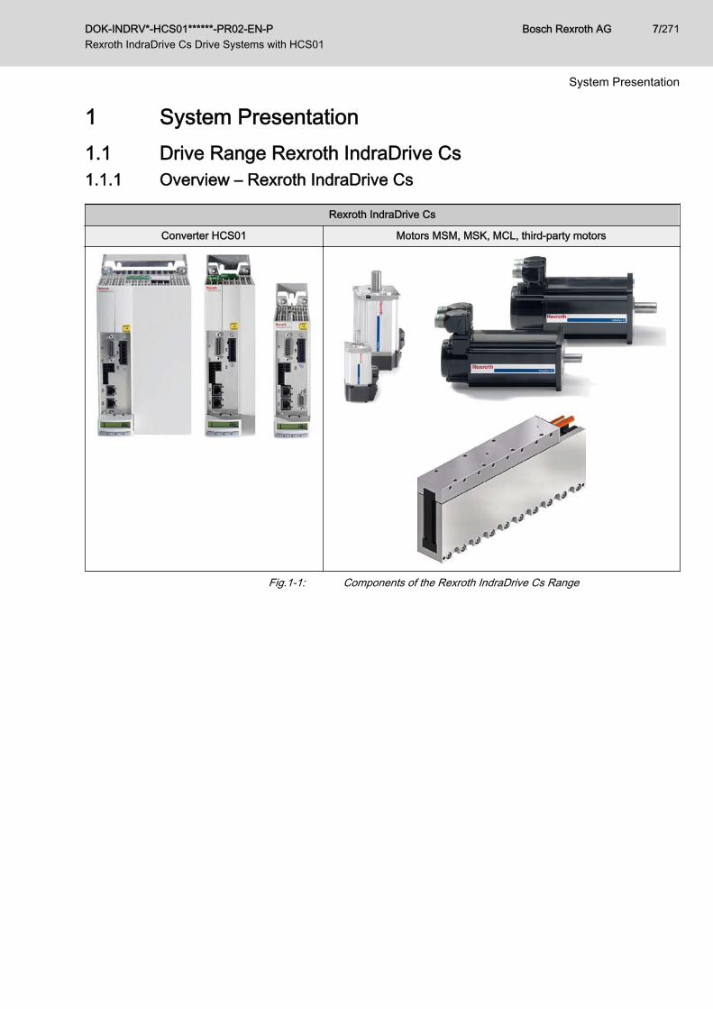
Rexroth IndraDrive Cs
Converter HCS01 Motors MSM, MSK, MCL, third-party motors
Fig.1-1: Components of the Rexroth IndraDrive Cs Range
DOK-INDRV*-HCS01******-PR02-EN-P Rexroth IndraDrive Cs Drive Systems with HCS01
Bosch Rexroth AG 7/271
System Presentation
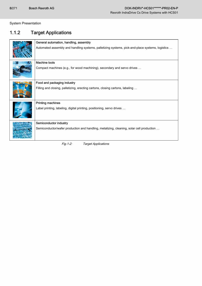
1.1.2 Target Applications
General automation, handling, assemblyAutomated assembly and handling systems, palletizing systems, pick-and-place systems, logistics …
Machine toolsCompact machines (e.g., for wood machining), secondary and servo drives …
Food and packaging industryFilling and closing, palletizing, erecting cartons, closing cartons, labeling …
Printing machinesLabel printing, labeling, digital printing, positioning, servo drives …
Semiconductor industrySemiconductor/wafer production and handling, metalizing, cleaning, solar cell production …
Fig.1-2: Target Applications
Bosch Rexroth AG DOK-INDRV*-HCS01******-PR02-EN-P Rexroth IndraDrive Cs Drive Systems with HCS01
8/271
System Presentation
1.1.3 FeaturesFunctional Features
● Compact type of construction● Degree of protection IP20● Control panel with programming module function● Scaleable signal processing and firmware● Multi-encoder interface for all standard encoders (HIPERFACE®, En‐
Dat2.1, SSI, TTL, sin/cos, resolver, MSM encoder)● DC bus connection (at HCS01.1E-W00xx-x-03 devices)● Analog input (14 bit, ±10 V)● 8 digital inputs
– 2 probe inputs– 1 combined I/O which can be configured as digital input or as digi‐
tal output● Performance-dependent fan control● Integrated brake current measurement and monitoring● Winding short circuit at motor output for shutdown as reaction to fatal er‐
rors● Compact MSM motors● 2 options for buffering the data of MSM encoders
– Battery box (SUP-E01-MSM-BATTERYBOX; mounting near themotor is possible; one battery box is required for each drive con‐troller)
– D-Sub connector (RGS0001/K01) for encoder cable (RKG0041)and connection of a battery or an uninterruptible power supply
● Hall sensor adapter box SHL03.1 to operate MCL linear motors with dig‐ital Hall sensors
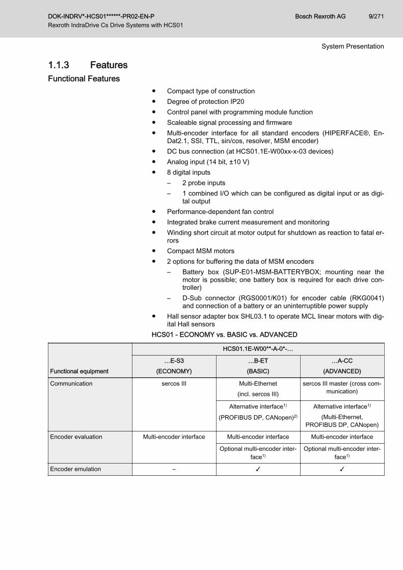
HCS01 - ECONOMY vs. BASIC vs. ADVANCED
Functional equipment
HCS01.1E-W00**-A-0*-…
…E-S3(ECONOMY)
…B-ET(BASIC)
…A-CC(ADVANCED)
Communication sercos III Multi-Ethernet(incl. sercos III)
sercos III master (cross com‐munication)
Alternative interface1)
(PROFIBUS DP, CANopen)2)
Alternative interface1)
(Multi-Ethernet,PROFIBUS DP, CANopen)
Encoder evaluation Multi-encoder interface Multi-encoder interface Multi-encoder interface
Optional multi-encoder inter‐face1)
Optional multi-encoder inter‐face1)
Encoder emulation – ✓ ✓
DOK-INDRV*-HCS01******-PR02-EN-P Rexroth IndraDrive Cs Drive Systems with HCS01
Bosch Rexroth AG 9/271
System Presentation
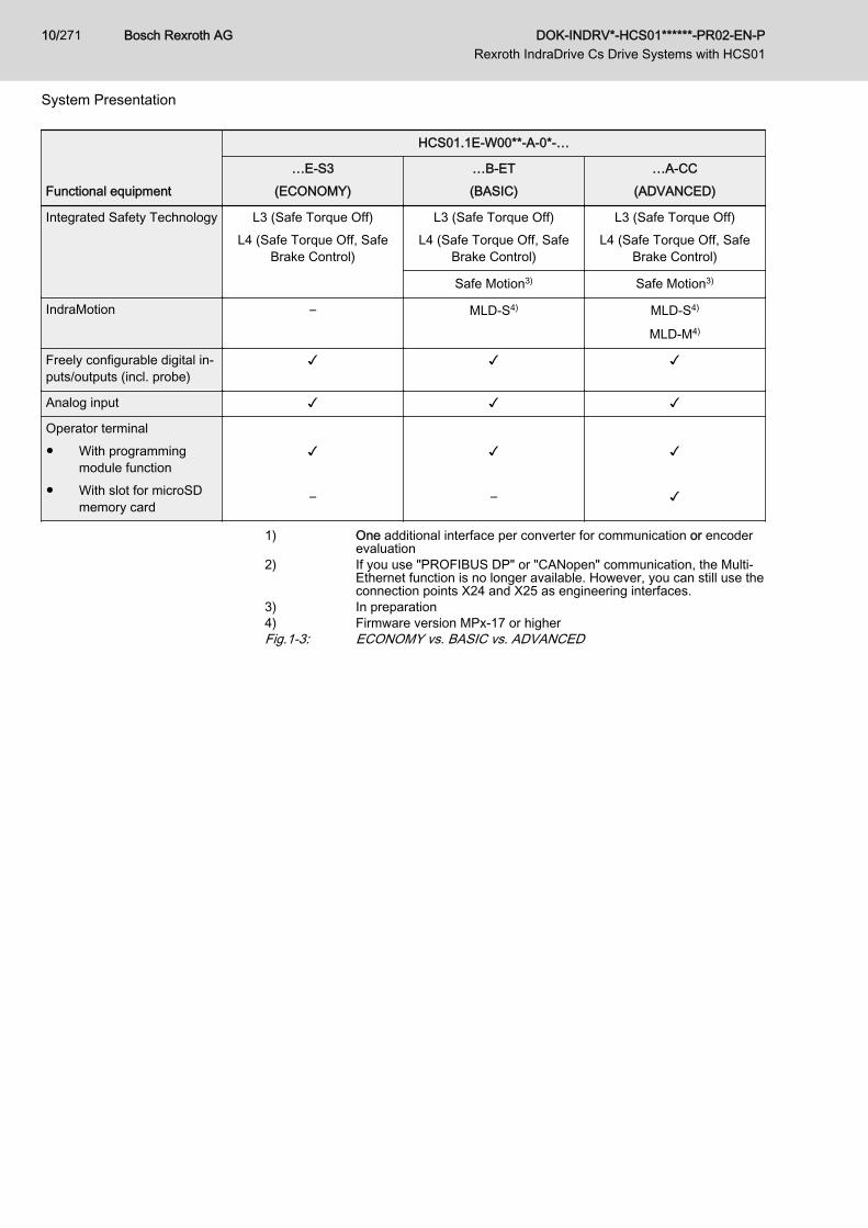
Functional equipment
HCS01.1E-W00**-A-0*-…
…E-S3(ECONOMY)
…B-ET(BASIC)
…A-CC(ADVANCED)
Integrated Safety Technology L3 (Safe Torque Off)L4 (Safe Torque Off, Safe
Brake Control)
L3 (Safe Torque Off)L4 (Safe Torque Off, Safe
Brake Control)
L3 (Safe Torque Off)L4 (Safe Torque Off, Safe
Brake Control)
Safe Motion3) Safe Motion3)
IndraMotion – MLD-S4) MLD-S4)
MLD-M4)
Freely configurable digital in‐puts/outputs (incl. probe)
✓ ✓ ✓
Analog input ✓ ✓ ✓
Operator terminal● With programming
module function● With slot for microSD
memory card
✓ –
✓ –
✓ ✓
1) One additional interface per converter for communication or encoderevaluation
2) If you use "PROFIBUS DP" or "CANopen" communication, the Multi-Ethernet function is no longer available. However, you can still use theconnection points X24 and X25 as engineering interfaces.
3) In preparation4) Firmware version MPx-17 or higherFig.1-3: ECONOMY vs. BASIC vs. ADVANCED
Bosch Rexroth AG DOK-INDRV*-HCS01******-PR02-EN-P Rexroth IndraDrive Cs Drive Systems with HCS01
10/271
System Presentation
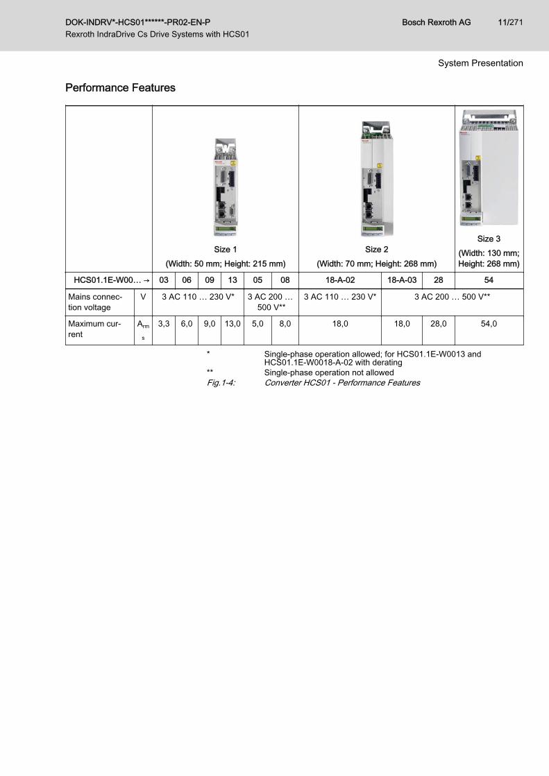
Performance Features
Size 1(Width: 50 mm; Height: 215 mm)
Size 2(Width: 70 mm; Height: 268 mm)
Size 3(Width: 130 mm;Height: 268 mm)
HCS01.1E-W00… → 03 06 09 13 05 08 18-A-02 18-A-03 28 54
Mains connec‐tion voltage
V 3 AC 110 … 230 V* 3 AC 200 … 500 V**
3 AC 110 … 230 V* 3 AC 200 … 500 V**
Maximum cur‐rent
Arm
s
3,3 6,0 9,0 13,0 5,0 8,0 18,0 18,0 28,0 54,0
* Single-phase operation allowed; for HCS01.1E-W0013 andHCS01.1E-W0018-A-02 with derating
** Single-phase operation not allowedFig.1-4: Converter HCS01 - Performance Features
DOK-INDRV*-HCS01******-PR02-EN-P Rexroth IndraDrive Cs Drive Systems with HCS01
Bosch Rexroth AG 11/271
System Presentation
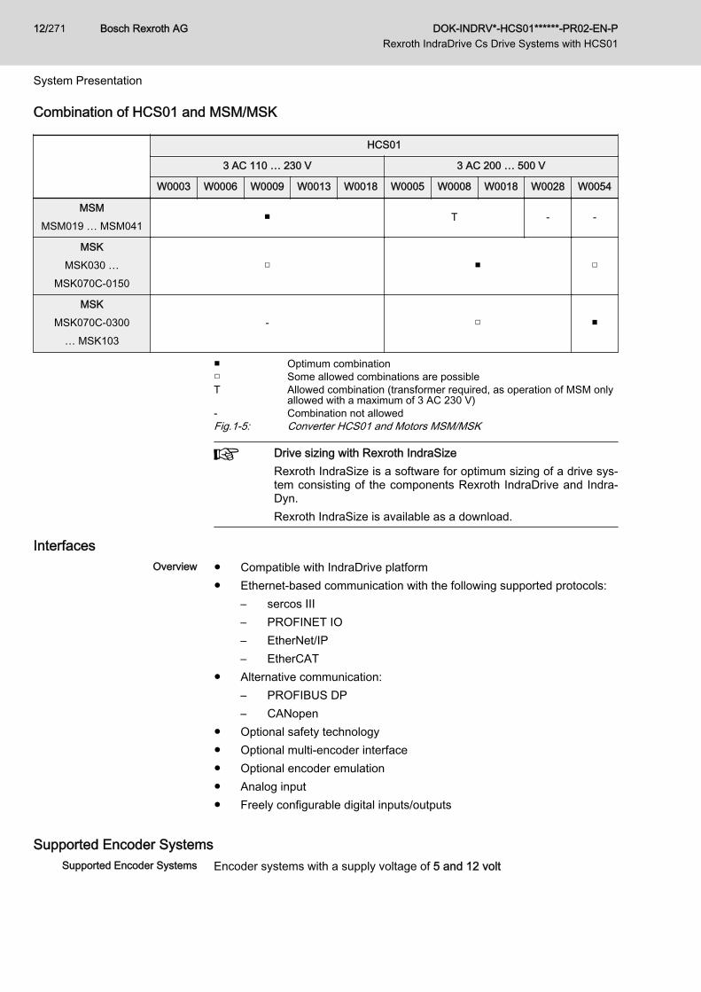
Combination of HCS01 and MSM/MSK
HCS01
3 AC 110 … 230 V 3 AC 200 … 500 V
W0003 W0006 W0009 W0013 W0018 W0005 W0008 W0018 W0028 W0054
MSMMSM019 … MSM041
■ T - -
MSKMSK030 …
MSK070C-0150□ ■ □
MSKMSK070C-0300
… MSK103- □ ■
■ Optimum combination□ Some allowed combinations are possibleT Allowed combination (transformer required, as operation of MSM only
allowed with a maximum of 3 AC 230 V)- Combination not allowedFig.1-5: Converter HCS01 and Motors MSM/MSK
Drive sizing with Rexroth IndraSizeRexroth IndraSize is a software for optimum sizing of a drive sys‐tem consisting of the components Rexroth IndraDrive and Indra‐Dyn.Rexroth IndraSize is available as a download.
InterfacesOverview ● Compatible with IndraDrive platform
● Ethernet-based communication with the following supported protocols:– sercos III– PROFINET IO– EtherNet/IP– EtherCAT
● Alternative communication:– PROFIBUS DP– CANopen
● Optional safety technology● Optional multi-encoder interface● Optional encoder emulation● Analog input● Freely configurable digital inputs/outputs
Supported Encoder SystemsSupported Encoder Systems Encoder systems with a supply voltage of 5 and 12 volt
Bosch Rexroth AG DOK-INDRV*-HCS01******-PR02-EN-P Rexroth IndraDrive Cs Drive Systems with HCS01
12/271
System Presentation

● MSM motor encoder● MSK motor encoder● Sin-cos encoder 1Vpp; HIPERFACE®● Sin-cos encoder 1Vpp; EnDat 2.1; (EnDat 2.2 in preparation)● Sin-cos encoder 1Vpp; with reference track● 5V-TTL square-wave encoder; with reference track● SSI● Combined encoder for SSI (combination of SSI and sin-cos encoder
1Vpp)● Resolver● Hall sensor box SHL02.1● Digital Hall sensor in conjunction with Hall sensor adapter box SHL03.1
DOK-INDRV*-HCS01******-PR02-EN-P Rexroth IndraDrive Cs Drive Systems with HCS01
Bosch Rexroth AG 13/271
System Presentation
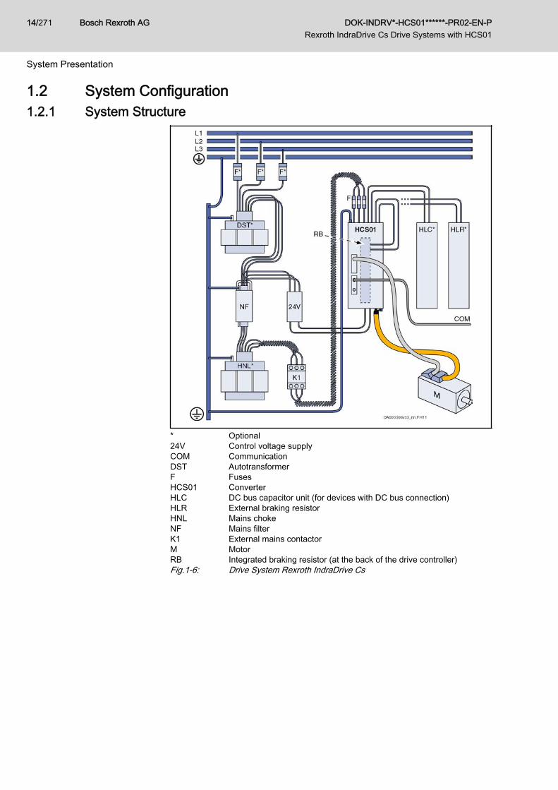
1.2 System Configuration1.2.1 System Structure
* Optional24V Control voltage supplyCOM CommunicationDST AutotransformerF FusesHCS01 ConverterHLC DC bus capacitor unit (for devices with DC bus connection)HLR External braking resistorHNL Mains chokeNF Mains filterK1 External mains contactorM MotorRB Integrated braking resistor (at the back of the drive controller)Fig.1-6: Drive System Rexroth IndraDrive Cs
Bosch Rexroth AG DOK-INDRV*-HCS01******-PR02-EN-P Rexroth IndraDrive Cs Drive Systems with HCS01
14/271
System Presentation
1.2.2 Components of the SystemDrive Controllers HCS01
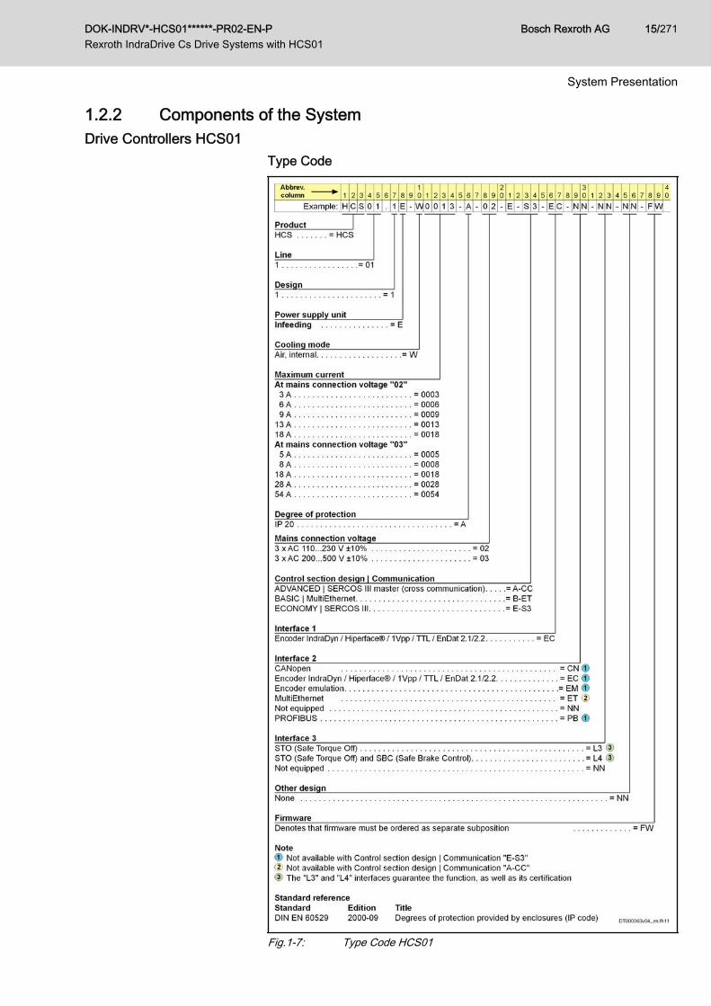
Type Code
Fig.1-7: Type Code HCS01
DOK-INDRV*-HCS01******-PR02-EN-P Rexroth IndraDrive Cs Drive Systems with HCS01
Bosch Rexroth AG 15/271
System Presentation
The figure illustrates the basic structure of the type code. Oursales representative will help you with the current state of availa‐ble versions.
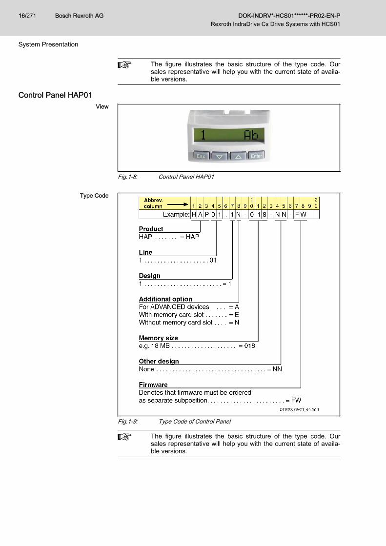
Control Panel HAP01View
Fig.1-8: Control Panel HAP01
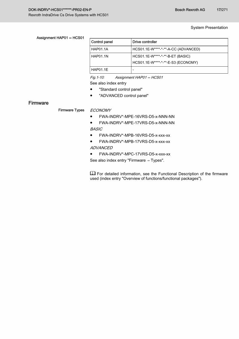
Type Code
Fig.1-9: Type Code of Control Panel
The figure illustrates the basic structure of the type code. Oursales representative will help you with the current state of availa‐ble versions.
Bosch Rexroth AG DOK-INDRV*-HCS01******-PR02-EN-P Rexroth IndraDrive Cs Drive Systems with HCS01
16/271
System Presentation
Assignment HAP01 ↔ HCS01Control panel Drive controller
HAP01.1A HCS01.1E-W****-*-**-A-CC (ADVANCED)
HAP01.1N HCS01.1E-W****-*-**-B-ET (BASIC)HCS01.1E-W****-*-**-E-S3 (ECONOMY)
HAP01.1E -
Fig.1-10: Assignment HAP01 ↔ HCS01See also index entry● "Standard control panel"● "ADVANCED control panel"
FirmwareFirmware Types ECONOMY
● FWA-INDRV*-MPE-16VRS-D5-x-NNN-NN● FWA-INDRV*-MPE-17VRS-D5-x-NNN-NNBASIC● FWA-INDRV*-MPB-16VRS-D5-x-xxx-xx● FWA-INDRV*-MPB-17VRS-D5-x-xxx-xxADVANCED● FWA-INDRV*-MPC-17VRS-D5-x-xxx-xxSee also index entry "Firmware → Types".
For detailed information, see the Functional Description of the firmwareused (index entry "Overview of functions/functional packages").
DOK-INDRV*-HCS01******-PR02-EN-P Rexroth IndraDrive Cs Drive Systems with HCS01
Bosch Rexroth AG 17/271
System Presentation
1.2.3 About This DocumentationPurpose
Personal injury and property damage causedby incorrect project planning for applications,machines and installations!
WARNING
Observe the contents of the documentations relevant to your drive system(see "Documentations").
This documentation contains● Overview information of the Rexroth IndraDrive Cs drive system● Description of the allowed combinations of Rexroth IndraDrive Cs sys‐
tem components● Selection of the system components of the Rexroth IndraDrive Cs drive
system● Specification applying to all components (ambient and operating condi‐
tions)● Application description of system characteristics
Bosch Rexroth AG DOK-INDRV*-HCS01******-PR02-EN-P Rexroth IndraDrive Cs Drive Systems with HCS01
18/271
System Presentation
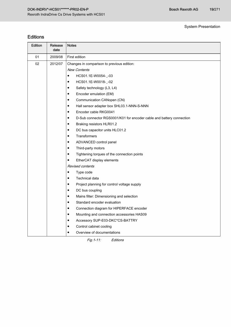
EditionsEdition Release
dateNotes
01 2009/08 First edition
02 2012/07 Changes in comparison to previous edition:New Contents● HCS01.1E-W0054-_-03● HCS01.1E-W0018-_-02● Safety technology (L3, L4)● Encoder emulation (EM)● Communication CANopen (CN)● Hall sensor adapter box SHL03.1-NNN-S-NNN● Encoder cable RKG0041● D-Sub connector RGS0001/K01 for encoder cable and battery connection● Braking resistors HLR01.2● DC bus capacitor units HLC01.2● Transformers● ADVANCED control panel● Third-party motors● Tightening torques of the connection points● EtherCAT display elementsRevised contents● Type code● Technical data● Project planning for control voltage supply● DC bus coupling● Mains filter: Dimensioning and selection● Standard encoder evaluation● Connection diagram for HIPERFACE encoder● Mounting and connection accessories HAS09● Accessory SUP-E03-DKC*CS-BATTRY● Control cabinet cooling● Overview of documentations
Fig.1-11: Editions
DOK-INDRV*-HCS01******-PR02-EN-P Rexroth IndraDrive Cs Drive Systems with HCS01
Bosch Rexroth AG 19/271
System Presentation
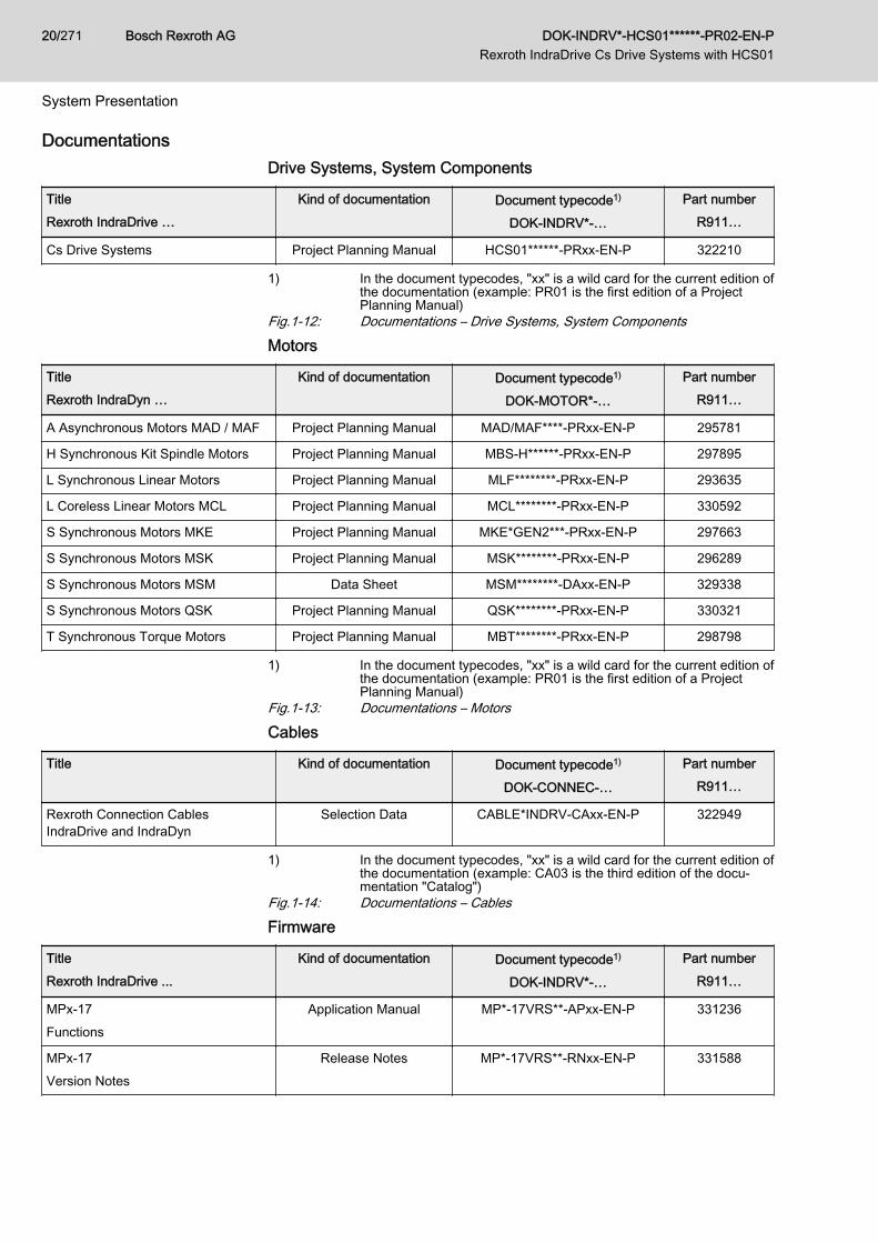
DocumentationsDrive Systems, System Components
TitleRexroth IndraDrive …
Kind of documentation Document typecode1)
DOK-INDRV*-…
Part numberR911…
Cs Drive Systems Project Planning Manual HCS01******-PRxx-EN-P 322210
1) In the document typecodes, "xx" is a wild card for the current edition ofthe documentation (example: PR01 is the first edition of a ProjectPlanning Manual)
Fig.1-12: Documentations – Drive Systems, System Components
Motors
TitleRexroth IndraDyn …
Kind of documentation Document typecode1)
DOK-MOTOR*-…
Part numberR911…
A Asynchronous Motors MAD / MAF Project Planning Manual MAD/MAF****-PRxx-EN-P 295781
H Synchronous Kit Spindle Motors Project Planning Manual MBS-H******-PRxx-EN-P 297895
L Synchronous Linear Motors Project Planning Manual MLF********-PRxx-EN-P 293635
L Coreless Linear Motors MCL Project Planning Manual MCL********-PRxx-EN-P 330592
S Synchronous Motors MKE Project Planning Manual MKE*GEN2***-PRxx-EN-P 297663
S Synchronous Motors MSK Project Planning Manual MSK********-PRxx-EN-P 296289
S Synchronous Motors MSM Data Sheet MSM********-DAxx-EN-P 329338
S Synchronous Motors QSK Project Planning Manual QSK********-PRxx-EN-P 330321
T Synchronous Torque Motors Project Planning Manual MBT********-PRxx-EN-P 298798
1) In the document typecodes, "xx" is a wild card for the current edition ofthe documentation (example: PR01 is the first edition of a ProjectPlanning Manual)
Fig.1-13: Documentations – Motors
Cables
Title Kind of documentation Document typecode1)
DOK-CONNEC-…
Part numberR911…
Rexroth Connection CablesIndraDrive and IndraDyn
Selection Data CABLE*INDRV-CAxx-EN-P 322949
1) In the document typecodes, "xx" is a wild card for the current edition ofthe documentation (example: CA03 is the third edition of the docu‐mentation "Catalog")
Fig.1-14: Documentations – Cables
Firmware
TitleRexroth IndraDrive ...
Kind of documentation Document typecode1)
DOK-INDRV*-…
Part numberR911…
MPx-17Functions
Application Manual MP*-17VRS**-APxx-EN-P 331236
MPx-17Version Notes
Release Notes MP*-17VRS**-RNxx-EN-P 331588
Bosch Rexroth AG DOK-INDRV*-HCS01******-PR02-EN-P Rexroth IndraDrive Cs Drive Systems with HCS01
20/271
System Presentation
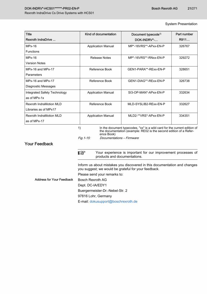
TitleRexroth IndraDrive ...
Kind of documentation Document typecode1)
DOK-INDRV*-…
Part numberR911…
MPx-16Functions
Application Manual MP*-16VRS**-APxx-EN-P 326767
MPx-16Version Notes
Release Notes MP*-16VRS**-RNxx-EN-P 329272
MPx-16 and MPx-17Parameters
Reference Book GEN1-PARA**-RExx-EN-P 328651
MPx-16 and MPx-17Diagnostic Messages
Reference Book GEN1-DIAG**-RExx-EN-P 326738
Integrated Safety Technologyas of MPx-1x
Application Manual SI3-OP-MAN*-APxx-EN-P 332634
Rexroth IndraMotion MLDLibraries as of MPx17
Reference Book MLD-SYSLIB2-RExx-EN-P 332627
Rexroth IndraMotion MLDas of MPx-17
Application Manual MLD2-**VRS*-APxx-EN-P 334351
1) In the document typecodes, "xx" is a wild card for the current edition ofthe documentation (example: RE02 is the second edition of a Refer‐ence Book)
Fig.1-15: Documentations – Firmware
Your Feedback
Your experience is important for our improvement processes ofproducts and documentations.
Inform us about mistakes you discovered in this documentation and changesyou suggest; we would be grateful for your feedback.Please send your remarks to:
Address for Your Feedback Bosch Rexroth AGDept. DC-IA/EDY1Buergermeister-Dr.-Nebel-Str. 297816 Lohr, GermanyE-mail: [email protected]
DOK-INDRV*-HCS01******-PR02-EN-P Rexroth IndraDrive Cs Drive Systems with HCS01
Bosch Rexroth AG 21/271
System Presentation

Bosch Rexroth AG DOK-INDRV*-HCS01******-PR02-EN-P Rexroth IndraDrive Cs Drive Systems with HCS01
22/271
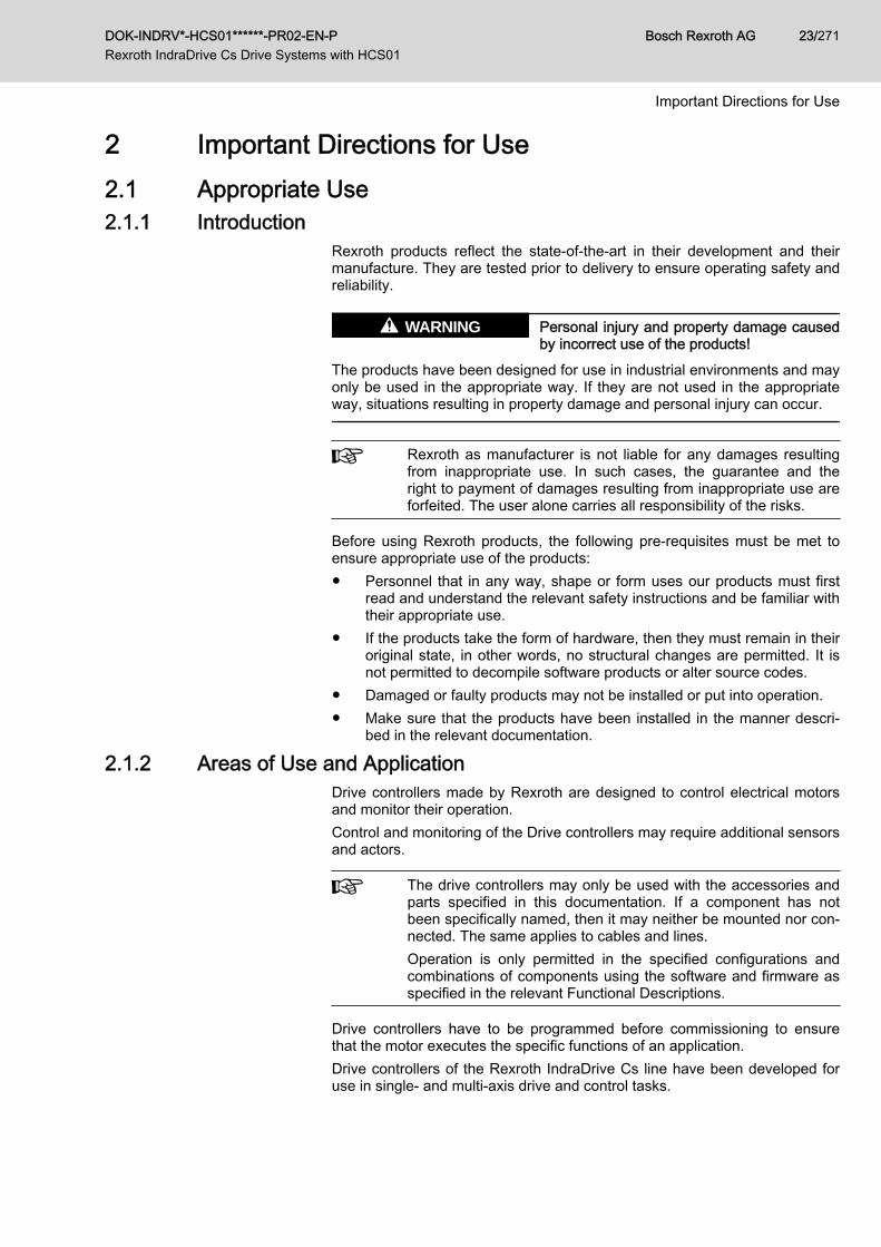
2 Important Directions for Use2.1 Appropriate Use2.1.1 Introduction
Rexroth products reflect the state-of-the-art in their development and theirmanufacture. They are tested prior to delivery to ensure operating safety andreliability.
Personal injury and property damage causedby incorrect use of the products!
WARNING
The products have been designed for use in industrial environments and mayonly be used in the appropriate way. If they are not used in the appropriateway, situations resulting in property damage and personal injury can occur.
Rexroth as manufacturer is not liable for any damages resultingfrom inappropriate use. In such cases, the guarantee and theright to payment of damages resulting from inappropriate use areforfeited. The user alone carries all responsibility of the risks.
Before using Rexroth products, the following pre-requisites must be met toensure appropriate use of the products:● Personnel that in any way, shape or form uses our products must first
read and understand the relevant safety instructions and be familiar withtheir appropriate use.
● If the products take the form of hardware, then they must remain in theiroriginal state, in other words, no structural changes are permitted. It isnot permitted to decompile software products or alter source codes.
● Damaged or faulty products may not be installed or put into operation.● Make sure that the products have been installed in the manner descri‐
bed in the relevant documentation.
2.1.2 Areas of Use and ApplicationDrive controllers made by Rexroth are designed to control electrical motorsand monitor their operation.Control and monitoring of the Drive controllers may require additional sensorsand actors.
The drive controllers may only be used with the accessories andparts specified in this documentation. If a component has notbeen specifically named, then it may neither be mounted nor con‐nected. The same applies to cables and lines.Operation is only permitted in the specified configurations andcombinations of components using the software and firmware asspecified in the relevant Functional Descriptions.
Drive controllers have to be programmed before commissioning to ensurethat the motor executes the specific functions of an application.Drive controllers of the Rexroth IndraDrive Cs line have been developed foruse in single- and multi-axis drive and control tasks.
DOK-INDRV*-HCS01******-PR02-EN-P Rexroth IndraDrive Cs Drive Systems with HCS01
Bosch Rexroth AG 23/271
Important Directions for Use
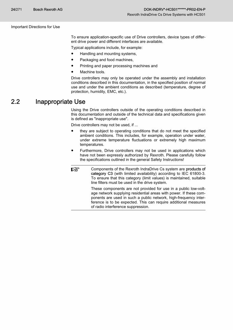
To ensure application-specific use of Drive controllers, device types of differ‐ent drive power and different interfaces are available.Typical applications include, for example:● Handling and mounting systems,● Packaging and food machines,● Printing and paper processing machines and● Machine tools.Drive controllers may only be operated under the assembly and installationconditions described in this documentation, in the specified position of normaluse and under the ambient conditions as described (temperature, degree ofprotection, humidity, EMC, etc.).
2.2 Inappropriate UseUsing the Drive controllers outside of the operating conditions described inthis documentation and outside of the technical data and specifications givenis defined as "inappropriate use".Drive controllers may not be used, if ...● they are subject to operating conditions that do not meet the specified
ambient conditions. This includes, for example, operation under water,under extreme temperature fluctuations or extremely high maximumtemperatures.
● Furthermore, Drive controllers may not be used in applications whichhave not been expressly authorized by Rexroth. Please carefully followthe specifications outlined in the general Safety Instructions!
Components of the Rexroth IndraDrive Cs system are products ofcategory C3 (with limited availability) according to IEC 61800‑3.To ensure that this category (limit values) is maintained, suitableline filters must be used in the drive system.These components are not provided for use in a public low-volt‐age network supplying residential areas with power. If these com‐ponents are used in such a public network, high-frequency inter‐ference is to be expected. This can require additional measuresof radio interference suppression.
Bosch Rexroth AG DOK-INDRV*-HCS01******-PR02-EN-P Rexroth IndraDrive Cs Drive Systems with HCS01
24/271
Important Directions for Use

3 Safety Instructions for Electric Drives and Controls3.1 Definitions of Terms
Application Documentation Application documentation comprises the entire documentation used to in‐form the user of the product about the use and safety-relevant features forconfiguring, integrating, installing, mounting, commissioning, operating, main‐taining, repairing and decommissioning the product. The following terms arealso used for this kind of documentation: User Guide, Operation Manual,Commissioning Manual, Instruction Manual, Project Planning Manual, Appli‐cation Manual, etc.
Component A component is a combination of elements with a specified function, whichare part of a piece of equipment, device or system. Components of the elec‐tric drive and control system are, for example, supply units, drive controllers,mains choke, mains filter, motors, cables, etc.
Control System A control system comprises several interconnected control componentsplaced on the market as a single functional unit.
Device A device is a finished product with a defined function, intended for users andplaced on the market as an individual piece of merchandise.
Electrical Equipment Electrical equipment encompasses all devices used to generate, convert,transmit, distribute or apply electrical energy, such as electric motors, trans‐formers, switching devices, cables, lines, power-consuming devices, circuitboard assemblies, plug-in units, control cabinets, etc.
Electric Drive System An electric drive system comprises all components from mains supply to mo‐tor shaft; this includes, for example, electric motor(s), motor encoder(s), sup‐ply units and drive controllers, as well as auxiliary and additional compo‐nents, such as mains filter, mains choke and the corresponding lines and ca‐bles.
Installation An installation consists of several devices or systems interconnected for adefined purpose and on a defined site which, however, are not intended to beplaced on the market as a single functional unit.
Machine A machine is the entirety of interconnected parts or units at least one ofwhich is movable. Thus, a machine consists of the appropriate machine driveelements, as well as control and power circuits, which have been assembledfor a specific application. A machine is, for example, intended for processing,treatment, movement or packaging of a material. The term "machine" alsocovers a combination of machines which are arranged and controlled in sucha way that they function as a unified whole.
Manufacturer The manufacturer is an individual or legal entity bearing responsibility for thedesign and manufacture of a product which is placed on the market in the in‐dividual's or legal entity's name. The manufacturer can use finished products,finished parts or finished elements, or contract out work to subcontractors.However, the manufacturer must always have overall control and possessthe required authority to take responsibility for the product.
Product Examples of a product: Device, component, part, system, software, firmware,among other things.
Project Planning Manual A project planning manual is part of the application documentation used tosupport the sizing and planning of systems, machines or installations.
Qualified Persons In terms of this application documentation, qualified persons are those per‐sons who are familiar with the installation, mounting, commissioning and op‐eration of the components of the electric drive and control system, as well aswith the hazards this implies, and who possess the qualifications their work
DOK-INDRV*-HCS01******-PR02-EN-P Rexroth IndraDrive Cs Drive Systems with HCS01
Bosch Rexroth AG 25/271
Safety Instructions for Electric Drives and Controls

requires. To comply with these qualifications, it is necessary, among otherthings,1) to be trained, instructed or authorized to switch electric circuits and devi‐ces safely on and off, to ground them and to mark them2) to be trained or instructed to maintain and use adequate safety equipment3) to attend a course of instruction in first aid
User A user is a person installing, commissioning or using a product which hasbeen placed on the market.
3.2 General Information3.2.1 Using the Safety Instructions and Passing Them on to Others
Do not attempt to install and operate the components of the electric drive andcontrol system without first reading all documentation provided with the prod‐uct. Read and understand these safety instructions and all user documenta‐tion prior to working with these components. If you do not have the user doc‐umentation for the components, contact your responsible Rexroth sales part‐ner. Ask for these documents to be sent immediately to the person or per‐sons responsible for the safe operation of the components.If the component is resold, rented and/or passed on to others in any otherform, these safety instructions must be delivered with the component in theofficial language of the user's country.Improper use of these components, failure to follow the safety instructions inthis document or tampering with the product, including disabling of safety de‐vices, could result in property damage, injury, electric shock or even death.
3.2.2 Requirements for Safe UseRead the following instructions before initial commissioning of the compo‐nents of the electric drive and control system in order to eliminate the risk ofinjury and/or property damage. You must follow these safety instructions.● Rexroth is not liable for damages resulting from failure to observe the
safety instructions.● Read the operating, maintenance and safety instructions in your lan‐
guage before commissioning. If you find that you cannot completely un‐derstand the application documentation in the available language,please ask your supplier to clarify.
● Proper and correct transport, storage, mounting and installation, as wellas care in operation and maintenance, are prerequisites for optimal andsafe operation of the component.
● Only qualified persons may work with components of the electric driveand control system or within its proximity.
● Only use accessories and spare parts approved by Rexroth.● Follow the safety regulations and requirements of the country in which
the components of the electric drive and control system are operated.● Only use the components of the electric drive and control system in the
manner that is defined as appropriate. See chapter "Appropriate Use".● The ambient and operating conditions given in the available application
documentation must be observed.● Applications for functional safety are only allowed if clearly and explicitly
specified in the application documentation "Integrated Safety Technolo‐
Bosch Rexroth AG DOK-INDRV*-HCS01******-PR02-EN-P Rexroth IndraDrive Cs Drive Systems with HCS01
26/271
Safety Instructions for Electric Drives and Controls
gy". If this is not the case, they are excluded. Functional safety is a safe‐ty concept in which measures of risk reduction for personal safety de‐pend on electrical, electronic or programmable control systems.
● The information given in the application documentation with regard tothe use of the delivered components contains only examples of applica‐tions and suggestions.The machine and installation manufacturers must– make sure that the delivered components are suited for their indi‐
vidual application and check the information given in this applica‐tion documentation with regard to the use of the components,
– make sure that their individual application complies with the appli‐cable safety regulations and standards and carry out the requiredmeasures, modifications and complements.
● Commissioning of the delivered components is only allowed once it issure that the machine or installation in which the components are instal‐led complies with the national regulations, safety specifications andstandards of the application.
● Operation is only allowed if the national EMC regulations for the applica‐tion are met.
● The instructions for installation in accordance with EMC requirementscan be found in the section on EMC in the respective application docu‐mentation.The machine or installation manufacturer is responsible for compliancewith the limit values as prescribed in the national regulations.
● The technical data, connection and installation conditions of the compo‐nents are specified in the respective application documentations andmust be followed at all times.
National regulations which the user must take into account● European countries: In accordance with European EN standards● United States of America (USA):
– National Electrical Code (NEC)– National Electrical Manufacturers Association (NEMA), as well as
local engineering regulations– Regulations of the National Fire Protection Association (NFPA)
● Canada: Canadian Standards Association (CSA)● Other countries:
– International Organization for Standardization (ISO)– International Electrotechnical Commission (IEC)
3.2.3 Hazards by Improper Use● High electrical voltage and high working current! Danger to life or seri‐
ous injury by electric shock!● High electrical voltage by incorrect connection! Danger to life or injury by
electric shock!● Dangerous movements! Danger to life, serious injury or property dam‐
age by unintended motor movements!● Health hazard for persons with heart pacemakers, metal implants and
hearing aids in proximity to electric drive systems!
DOK-INDRV*-HCS01******-PR02-EN-P Rexroth IndraDrive Cs Drive Systems with HCS01
Bosch Rexroth AG 27/271
Safety Instructions for Electric Drives and Controls

● Risk of burns by hot housing surfaces!● Risk of injury by improper handling! Injury by crushing, shearing, cutting,
hitting!● Risk of injury by improper handling of batteries!● Risk of injury by improper handling of pressurized lines!
3.3 Instructions with Regard to Specific Dangers3.3.1 Protection Against Contact With Electrical Parts and Housings
This section concerns components of the electric drive and con‐trol system with voltages of more than 50 volts.
Contact with parts conducting voltages above 50 volts can cause personaldanger and electric shock. When operating components of the electric driveand control system, it is unavoidable that some parts of these componentsconduct dangerous voltage. High electrical voltage! Danger to life, risk of injury by electric shock or seri‐ous injury!● Only qualified persons are allowed to operate, maintain and/or repair the
components of the electric drive and control system.● Follow the general installation and safety regulations when working on
power installations.● Before switching on, the equipment grounding conductor must have
been permanently connected to all electric components in accordancewith the connection diagram.
● Even for brief measurements or tests, operation is only allowed if theequipment grounding conductor has been permanently connected to thepoints of the components provided for this purpose.
● Before accessing electrical parts with voltage potentials higher than50 V, you must disconnect electric components from the mains or fromthe power supply unit. Secure the electric component from reconnec‐tion.
● With electric components, observe the following aspects:Always wait 30 minutes after switching off power to allow live capacitorsto discharge before accessing an electric component. Measure the elec‐trical voltage of live parts before beginning to work to make sure that theequipment is safe to touch.
● Install the covers and guards provided for this purpose before switchingon.
● Never touch electrical connection points of the components while poweris turned on.
● Do not remove or plug in connectors when the component has beenpowered.
● Under specific conditions, electric drive systems can be operated atmains protected by residual-current-operated circuit-breakers sensitiveto universal current (RCDs/RCMs).
Bosch Rexroth AG DOK-INDRV*-HCS01******-PR02-EN-P Rexroth IndraDrive Cs Drive Systems with HCS01
28/271
Safety Instructions for Electric Drives and Controls
● Secure built-in devices from penetrating foreign objects and water, aswell as from direct contact, by providing an external housing, for exam‐ple a control cabinet.
High housing voltage and high leakage current! Danger to life, risk of injuryby electric shock!● Before switching on and before commissioning, ground or connect the
components of the electric drive and control system to the equipmentgrounding conductor at the grounding points.
● Connect the equipment grounding conductor of the components of theelectric drive and control system permanently to the main power supplyat all times. The leakage current is greater than 3.5 mA.
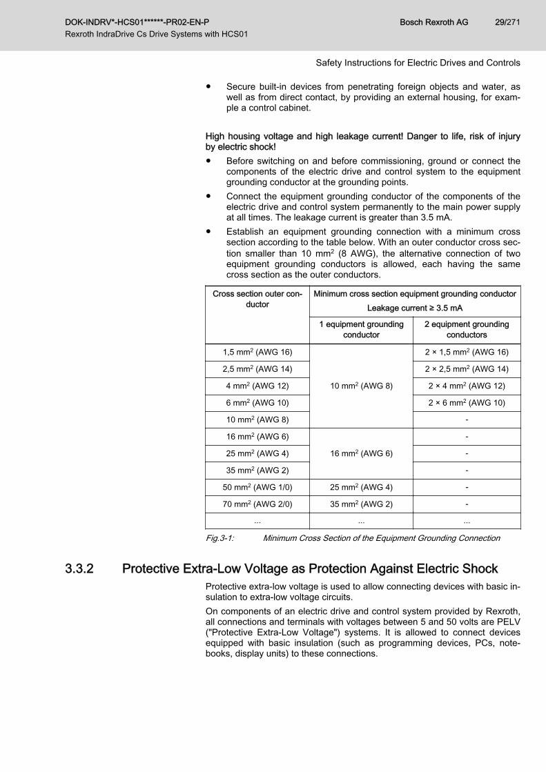
● Establish an equipment grounding connection with a minimum crosssection according to the table below. With an outer conductor cross sec‐tion smaller than 10 mm2 (8 AWG), the alternative connection of twoequipment grounding conductors is allowed, each having the samecross section as the outer conductors.
Cross section outer con‐ductor
Minimum cross section equipment grounding conductorLeakage current ≥ 3.5 mA
1 equipment groundingconductor
2 equipment groundingconductors
1,5 mm2 (AWG 16)
10 mm2 (AWG 8)
2 × 1,5 mm2 (AWG 16)
2,5 mm2 (AWG 14) 2 × 2,5 mm2 (AWG 14)
4 mm2 (AWG 12) 2 × 4 mm2 (AWG 12)
6 mm2 (AWG 10) 2 × 6 mm2 (AWG 10)
10 mm2 (AWG 8) -
16 mm2 (AWG 6)
16 mm2 (AWG 6)
-
25 mm2 (AWG 4) -
35 mm2 (AWG 2) -
50 mm2 (AWG 1/0) 25 mm2 (AWG 4) -
70 mm2 (AWG 2/0) 35 mm2 (AWG 2) -
... ... ...
Fig.3-1: Minimum Cross Section of the Equipment Grounding Connection
3.3.2 Protective Extra-Low Voltage as Protection Against Electric Shock Protective extra-low voltage is used to allow connecting devices with basic in‐sulation to extra-low voltage circuits.On components of an electric drive and control system provided by Rexroth,all connections and terminals with voltages between 5 and 50 volts are PELV("Protective Extra-Low Voltage") systems. It is allowed to connect devicesequipped with basic insulation (such as programming devices, PCs, note‐books, display units) to these connections.
DOK-INDRV*-HCS01******-PR02-EN-P Rexroth IndraDrive Cs Drive Systems with HCS01
Bosch Rexroth AG 29/271
Safety Instructions for Electric Drives and Controls

Danger to life, risk of injury by electric shock! High electrical voltage by incor‐rect connection!If extra-low voltage circuits of devices containing voltages and circuits ofmore than 50 volts (e.g., the mains connection) are connected to Rexrothproducts, the connected extra-low voltage circuits must comply with the re‐quirements for PELV ("Protective Extra-Low Voltage").
3.3.3 Protection Against Dangerous MovementsDangerous movements can be caused by faulty control of connected motors.Some common examples are:● Improper or wrong wiring or cable connection● Operator errors● Wrong input of parameters before commissioning● Malfunction of sensors and encoders● Defective components● Software or firmware errorsThese errors can occur immediately after equipment is switched on or evenafter an unspecified time of trouble-free operation.The monitoring functions in the components of the electric drive and controlsystem will normally be sufficient to avoid malfunction in the connecteddrives. Regarding personal safety, especially the danger of injury and/orproperty damage, this alone cannot be relied upon to ensure complete safety.Until the integrated monitoring functions become effective, it must be as‐sumed in any case that faulty drive movements will occur. The extent of faultydrive movements depends upon the type of control and the state of opera‐tion. Dangerous movements! Danger to life, risk of injury, serious injury or propertydamage!A risk assessment must be prepared for the installation or machine, with itsspecific conditions, in which the components of the electric drive and controlsystem are installed.As a result of the risk assessment, the user must provide for monitoring func‐tions and higher-level measures on the installation side for personal safety.The safety regulations applicable to the installation or machine must be takeninto consideration. Unintended machine movements or other malfunctionsare possible if safety devices are disabled, bypassed or not activated.To avoid accidents, injury and/or property damage:● Keep free and clear of the machine’s range of motion and moving ma‐
chine parts. Prevent personnel from accidentally entering the machine’srange of motion by using, for example:– Safety fences– Safety guards– Protective coverings– Light barriers
● Make sure the safety fences and protective coverings are strong enoughto resist maximum possible kinetic energy.
● Mount emergency stopping switches in the immediate reach of the oper‐ator. Before commissioning, verify that the emergency stopping equip‐
Bosch Rexroth AG DOK-INDRV*-HCS01******-PR02-EN-P Rexroth IndraDrive Cs Drive Systems with HCS01
30/271
Safety Instructions for Electric Drives and Controls

ment works. Do not operate the machine if the emergency stoppingswitch is not working.
● Prevent unintended start-up. Isolate the drive power connection bymeans of OFF switches/OFF buttons or use a safe starting lockout.
● Make sure that the drives are brought to safe standstill before accessingor entering the danger zone.
● Additionally secure vertical axes against falling or dropping after switch‐ing off the motor power by, for example,– mechanically securing the vertical axes,– adding an external braking/arrester/clamping mechanism or– ensuring sufficient counterbalancing of the vertical axes.
● The standard equipment motor holding brake or an external holdingbrake controlled by the drive controller is not sufficient to guarantee per‐sonal safety!
● Disconnect electrical power to the components of the electric drive andcontrol system using the master switch and secure them from reconnec‐tion ("lock out") for:– Maintenance and repair work– Cleaning of equipment– Long periods of discontinued equipment use
● Prevent the operation of high-frequency, remote control and radio equip‐ment near components of the electric drive and control system and theirsupply leads. If the use of these devices cannot be avoided, check themachine or installation, at initial commissioning of the electric drive andcontrol system, for possible malfunctions when operating such high-fre‐quency, remote control and radio equipment in its possible positions ofnormal use. It might possibly be necessary to perform a special electro‐magnetic compatibility (EMC) test.
3.3.4 Protection Against Magnetic and Electromagnetic Fields During Oper‐ation and Mounting
Magnetic and electromagnetic fields generated by current-carrying conduc‐tors or permanent magnets of electric motors represent a serious danger topersons with heart pacemakers, metal implants and hearing aids.Health hazard for persons with heart pacemakers, metal implants and hear‐ing aids in proximity to electric components!● Persons with heart pacemakers and metal implants are not allowed to
enter the following areas:– Areas in which components of the electric drive and control sys‐
tems are mounted, commissioned and operated.– Areas in which parts of motors with permanent magnets are stored,
repaired or mounted.● If it is necessary for somebody with a heart pacemaker to enter such an
area, a doctor must be consulted prior to doing so. The noise immunityof implanted heart pacemakers differs so greatly that no general rulescan be given.
● Those with metal implants or metal pieces, as well as with hearing aids,must consult a doctor before they enter the areas described above.
DOK-INDRV*-HCS01******-PR02-EN-P Rexroth IndraDrive Cs Drive Systems with HCS01
Bosch Rexroth AG 31/271
Safety Instructions for Electric Drives and Controls

3.3.5 Protection Against Contact With Hot PartsHot surfaces of components of the electric drive and control system. Risk ofburns!● Do not touch hot surfaces of, for example, braking resistors, heat sinks,
supply units and drive controllers, motors, windings and laminatedcores!
● According to the operating conditions, temperatures of the surfaces canbe higher than 60 °C (140 °F) during or after operation.
● Before touching motors after having switched them off, let them cooldown for a sufficient period of time. Cooling down can require up to 140minutes! The time required for cooling down is approximately five timesthe thermal time constant specified in the technical data.
● After switching chokes, supply units and drive controllers off, wait 15 mi‐nutes to allow them to cool down before touching them.
● Wear safety gloves or do not work at hot surfaces.● For certain applications, and in accordance with the respective safety
regulations, the manufacturer of the machine or installation must takemeasures to avoid injuries caused by burns in the final application.These measures can be, for example: Warnings at the machine or in‐stallation, guards (shieldings or barriers) or safety instructions in the ap‐plication documentation.
3.3.6 Protection During Handling and MountingRisk of injury by improper handling! Injury by crushing, shearing, cutting, hit‐ting!● Observe the relevant statutory regulations of accident prevention.● Use suitable equipment for mounting and transport.● Avoid jamming and crushing by appropriate measures.● Always use suitable tools. Use special tools if specified.● Use lifting equipment and tools in the correct manner.● Use suitable protective equipment (hard hat, safety goggles, safety
shoes, safety gloves, for example).● Do not stand under hanging loads.● Immediately clean up any spilled liquids from the floor due to the risk of
falling!
3.3.7 Battery SafetyBatteries consist of active chemicals in a solid housing. Therefore, improperhandling can cause injury or property damage.Risk of injury by improper handling!● Do not attempt to reactivate low batteries by heating or other methods
(risk of explosion and cauterization).● Do not attempt to recharge the batteries as this may cause leakage or
explosion.● Do not throw batteries into open flames.● Do not dismantle batteries.
Bosch Rexroth AG DOK-INDRV*-HCS01******-PR02-EN-P Rexroth IndraDrive Cs Drive Systems with HCS01
32/271
Safety Instructions for Electric Drives and Controls

● When replacing the battery/batteries, do not damage the electrical partsinstalled in the devices.
● Only use the battery types specified for the product.
Environmental protection and disposal! The batteries contained inthe product are considered dangerous goods during land, air, andsea transport (risk of explosion) in the sense of the legal regula‐tions. Dispose of used batteries separately from other waste. Ob‐serve the national regulations of your country.
3.3.8 Protection Against Pressurized SystemsAccording to the information given in the Project Planning Manuals, motorsand components cooled with liquids and compressed air can be partially sup‐plied with externally fed, pressurized media, such as compressed air, hy‐draulics oil, cooling liquids and cooling lubricants. Improper handling of theconnected supply systems, supply lines or connections can cause injuries orproperty damage.Risk of injury by improper handling of pressurized lines!● Do not attempt to disconnect, open or cut pressurized lines (risk of ex‐
plosion).● Observe the respective manufacturer's operating instructions.● Before dismounting lines, relieve pressure and empty medium.● Use suitable protective equipment (safety goggles, safety shoes, safety
gloves, for example).● Immediately clean up any spilled liquids from the floor due to the risk of
falling!
Environmental protection and disposal! The agents (e.g., fluids)used to operate the product might not be environmentally friendly.Dispose of agents harmful to the environment separately fromother waste. Observe the national regulations of your country.
3.4 Explanation of Signal Words and the Safety Alert SymbolThe Safety Instructions in the available application documentation containspecific signal words (DANGER, WARNING, CAUTION or NOTICE) and,where required, a safety alert symbol (in accordance withANSI Z535.6-2011).The signal word is meant to draw the reader's attention to the safety instruc‐tion and identifies the hazard severity.The safety alert symbol (a triangle with an exclamation point), which pre‐cedes the signal words DANGER, WARNING and CAUTION, is used to alertthe reader to personal injury hazards.
DANGERIn case of non-compliance with this safety instruction, death or serious injurywill occur.
DOK-INDRV*-HCS01******-PR02-EN-P Rexroth IndraDrive Cs Drive Systems with HCS01
Bosch Rexroth AG 33/271
Safety Instructions for Electric Drives and Controls
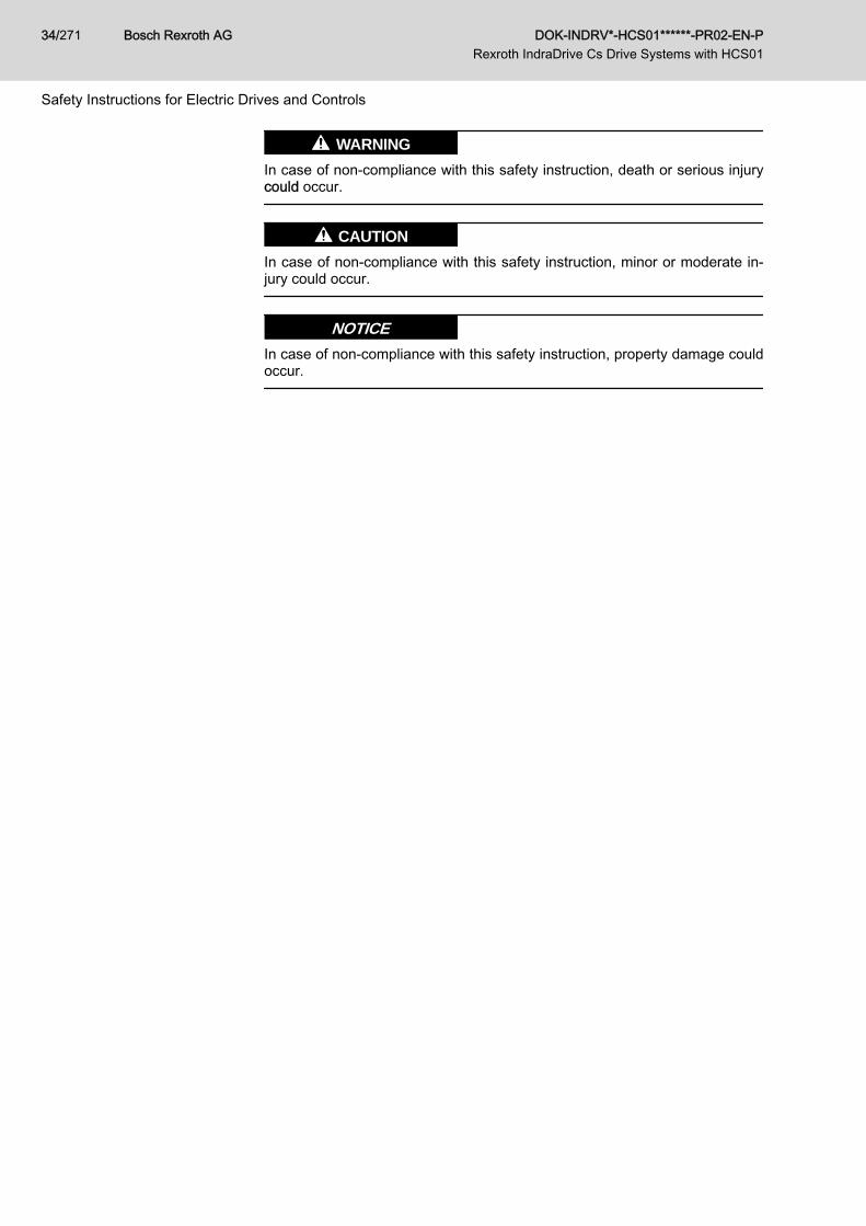
WARNINGIn case of non-compliance with this safety instruction, death or serious injurycould occur.
CAUTIONIn case of non-compliance with this safety instruction, minor or moderate in‐jury could occur.
NOTICEIn case of non-compliance with this safety instruction, property damage couldoccur.
Bosch Rexroth AG DOK-INDRV*-HCS01******-PR02-EN-P Rexroth IndraDrive Cs Drive Systems with HCS01
34/271
Safety Instructions for Electric Drives and Controls
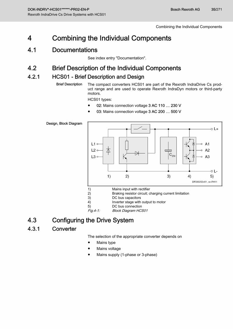
4 Combining the Individual Components4.1 Documentations
See index entry "Documentation".
4.2 Brief Description of the Individual Components4.2.1 HCS01 - Brief Description and Design
Brief Description The compact converters HCS01 are part of the Rexroth IndraDrive Cs prod‐uct range and are used to operate Rexroth IndraDyn motors or third-partymotors.HCS01 types:● 02: Mains connection voltage 3 AC 110 … 230 V● 03: Mains connection voltage 3 AC 200 … 500 V
Design, Block Diagram
1) Mains input with rectifier2) Braking resistor circuit; charging current limitation3) DC bus capacitors4) Inverter stage with output to motor5) DC bus connectionFig.4-1: Block Diagram HCS01
4.3 Configuring the Drive System4.3.1 Converter
The selection of the appropriate converter depends on● Mains type● Mains voltage● Mains supply (1-phase or 3-phase)
DOK-INDRV*-HCS01******-PR02-EN-P Rexroth IndraDrive Cs Drive Systems with HCS01
Bosch Rexroth AG 35/271
Combining the Individual Components
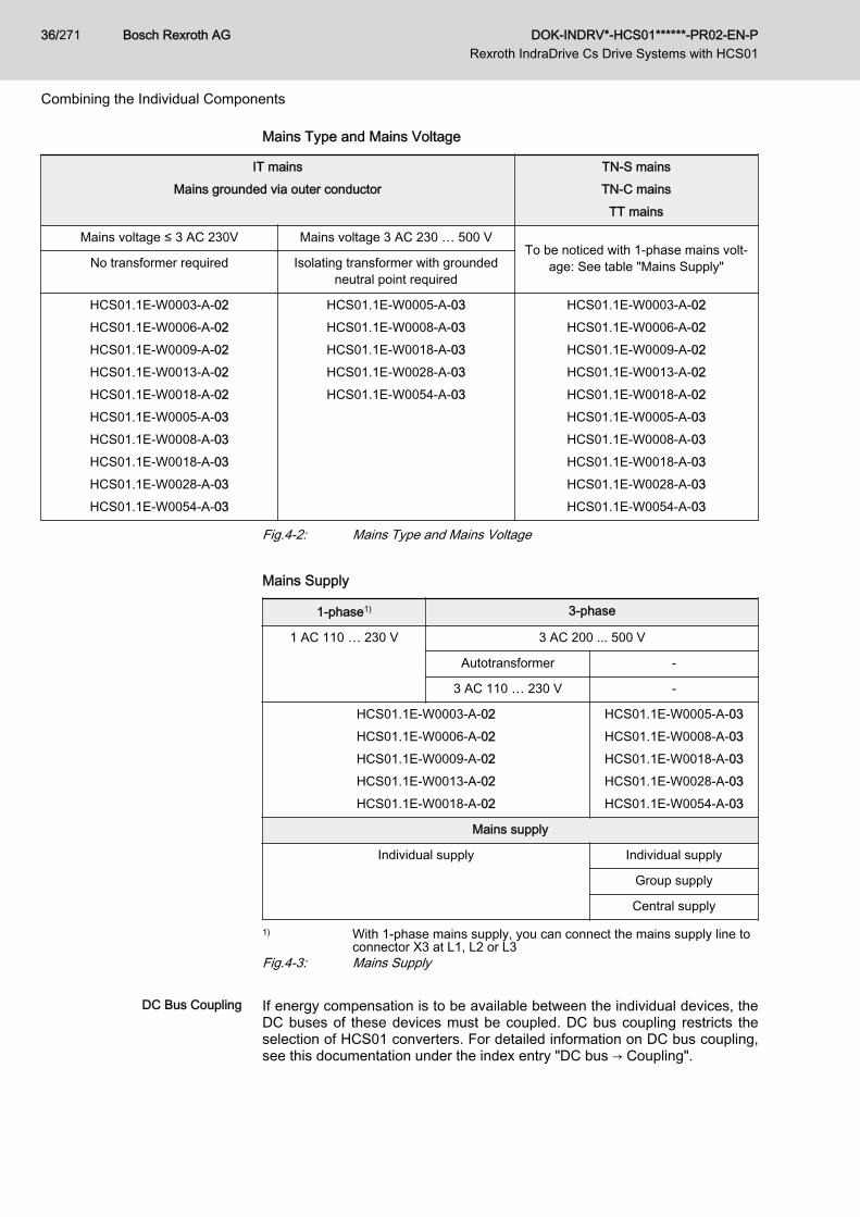
Mains Type and Mains Voltage
IT mainsMains grounded via outer conductor
TN-S mainsTN-C mains
TT mains
Mains voltage ≤ 3 AC 230V Mains voltage 3 AC 230 … 500 VTo be noticed with 1-phase mains volt‐
age: See table "Mains Supply"No transformer required Isolating transformer with groundedneutral point required
HCS01.1E-W0003-A-02HCS01.1E-W0006-A-02HCS01.1E-W0009-A-02HCS01.1E-W0013-A-02HCS01.1E-W0018-A-02HCS01.1E-W0005-A-03HCS01.1E-W0008-A-03HCS01.1E-W0018-A-03HCS01.1E-W0028-A-03HCS01.1E-W0054-A-03
HCS01.1E-W0005-A-03HCS01.1E-W0008-A-03HCS01.1E-W0018-A-03HCS01.1E-W0028-A-03HCS01.1E-W0054-A-03
HCS01.1E-W0003-A-02HCS01.1E-W0006-A-02HCS01.1E-W0009-A-02HCS01.1E-W0013-A-02HCS01.1E-W0018-A-02HCS01.1E-W0005-A-03HCS01.1E-W0008-A-03HCS01.1E-W0018-A-03HCS01.1E-W0028-A-03HCS01.1E-W0054-A-03
Fig.4-2: Mains Type and Mains Voltage Mains Supply
1-phase1) 3-phase
1 AC 110 … 230 V 3 AC 200 ... 500 V
Autotransformer -
3 AC 110 … 230 V -
HCS01.1E-W0003-A-02HCS01.1E-W0006-A-02HCS01.1E-W0009-A-02HCS01.1E-W0013-A-02HCS01.1E-W0018-A-02
HCS01.1E-W0005-A-03HCS01.1E-W0008-A-03HCS01.1E-W0018-A-03HCS01.1E-W0028-A-03HCS01.1E-W0054-A-03
Mains supply
Individual supply Individual supply
Group supply
Central supply
1) With 1-phase mains supply, you can connect the mains supply line toconnector X3 at L1, L2 or L3
Fig.4-3: Mains Supply
DC Bus Coupling If energy compensation is to be available between the individual devices, theDC buses of these devices must be coupled. DC bus coupling restricts theselection of HCS01 converters. For detailed information on DC bus coupling,see this documentation under the index entry "DC bus → Coupling".
Bosch Rexroth AG DOK-INDRV*-HCS01******-PR02-EN-P Rexroth IndraDrive Cs Drive Systems with HCS01
36/271
Combining the Individual Components
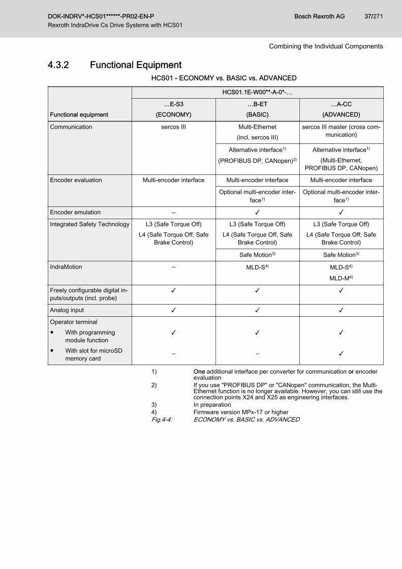
4.3.2 Functional EquipmentHCS01 - ECONOMY vs. BASIC vs. ADVANCED
Functional equipment
HCS01.1E-W00**-A-0*-…
…E-S3(ECONOMY)
…B-ET(BASIC)
…A-CC(ADVANCED)
Communication sercos III Multi-Ethernet(incl. sercos III)
sercos III master (cross com‐munication)
Alternative interface1)
(PROFIBUS DP, CANopen)2)
Alternative interface1)
(Multi-Ethernet,PROFIBUS DP, CANopen)
Encoder evaluation Multi-encoder interface Multi-encoder interface Multi-encoder interface
Optional multi-encoder inter‐face1)
Optional multi-encoder inter‐face1)
Encoder emulation – ✓ ✓
Integrated Safety Technology L3 (Safe Torque Off)L4 (Safe Torque Off, Safe
Brake Control)
L3 (Safe Torque Off)L4 (Safe Torque Off, Safe
Brake Control)
L3 (Safe Torque Off)L4 (Safe Torque Off, Safe
Brake Control)
Safe Motion3) Safe Motion3)
IndraMotion – MLD-S4) MLD-S4)
MLD-M4)
Freely configurable digital in‐puts/outputs (incl. probe)
✓ ✓ ✓
Analog input ✓ ✓ ✓
Operator terminal● With programming
module function● With slot for microSD
memory card
✓ –
✓ –
✓ ✓
1) One additional interface per converter for communication or encoderevaluation
2) If you use "PROFIBUS DP" or "CANopen" communication, the Multi-Ethernet function is no longer available. However, you can still use theconnection points X24 and X25 as engineering interfaces.
3) In preparation4) Firmware version MPx-17 or higherFig.4-4: ECONOMY vs. BASIC vs. ADVANCED
DOK-INDRV*-HCS01******-PR02-EN-P Rexroth IndraDrive Cs Drive Systems with HCS01
Bosch Rexroth AG 37/271
Combining the Individual Components
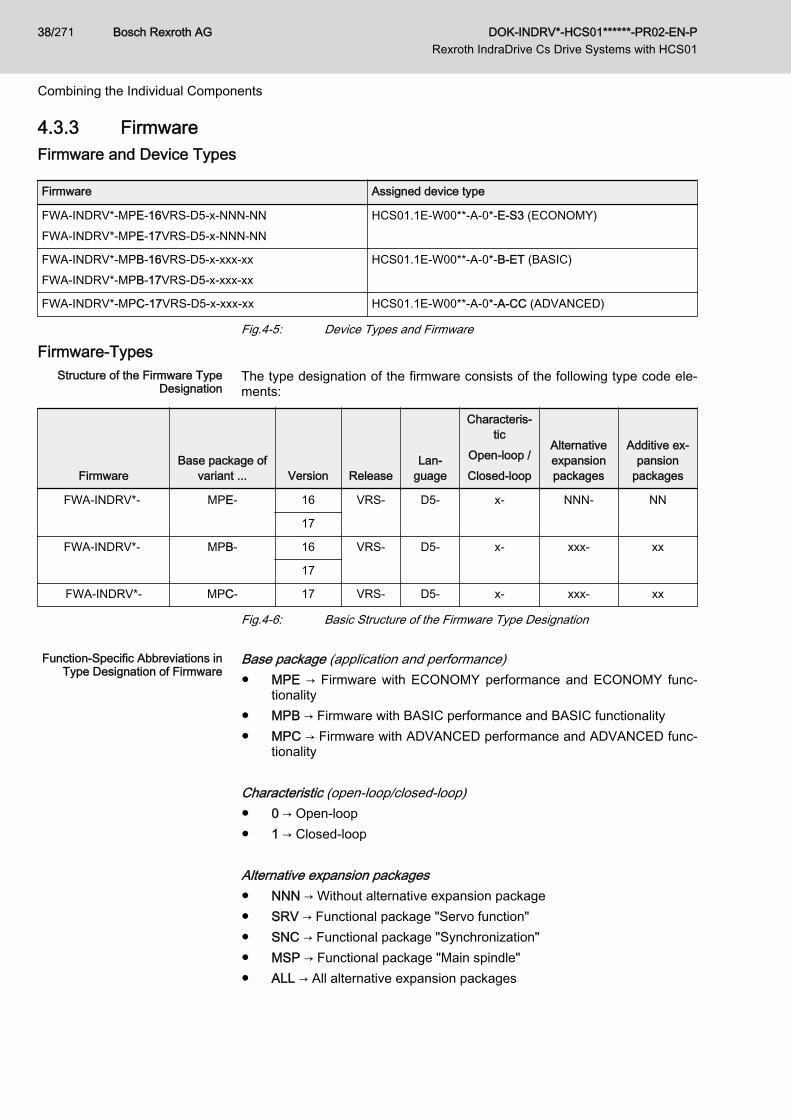
4.3.3 FirmwareFirmware and Device Types
Firmware Assigned device type
FWA-INDRV*-MPE-16VRS-D5-x-NNN-NNFWA-INDRV*-MPE-17VRS-D5-x-NNN-NN
HCS01.1E-W00**-A-0*-E-S3 (ECONOMY)
FWA-INDRV*-MPB-16VRS-D5-x-xxx-xxFWA-INDRV*-MPB-17VRS-D5-x-xxx-xx
HCS01.1E-W00**-A-0*-B-ET (BASIC)
FWA-INDRV*-MPC-17VRS-D5-x-xxx-xx HCS01.1E-W00**-A-0*-A-CC (ADVANCED)
Fig.4-5: Device Types and Firmware
Firmware-TypesStructure of the Firmware Type
DesignationThe type designation of the firmware consists of the following type code ele‐ments:
FirmwareBase package of
variant ... Version ReleaseLan‐
guage
Characteris‐tic
Open-loop /Closed-loop
Alternativeexpansionpackages
Additive ex‐pansion
packages
FWA-INDRV*- MPE- 16 VRS- D5- x- NNN- NN
17
FWA-INDRV*- MPB- 16 VRS- D5- x- xxx- xx
17
FWA-INDRV*- MPC- 17 VRS- D5- x- xxx- xx
Fig.4-6: Basic Structure of the Firmware Type Designation
Function-Specific Abbreviations inType Designation of Firmware
Base package (application and performance)● MPE → Firmware with ECONOMY performance and ECONOMY func‐
tionality● MPB → Firmware with BASIC performance and BASIC functionality● MPC → Firmware with ADVANCED performance and ADVANCED func‐
tionality Characteristic (open-loop/closed-loop)● 0 → Open-loop● 1 → Closed-loop Alternative expansion packages● NNN → Without alternative expansion package● SRV → Functional package "Servo function"● SNC → Functional package "Synchronization"● MSP → Functional package "Main spindle"● ALL → All alternative expansion packages
Bosch Rexroth AG DOK-INDRV*-HCS01******-PR02-EN-P Rexroth IndraDrive Cs Drive Systems with HCS01
38/271
Combining the Individual Components
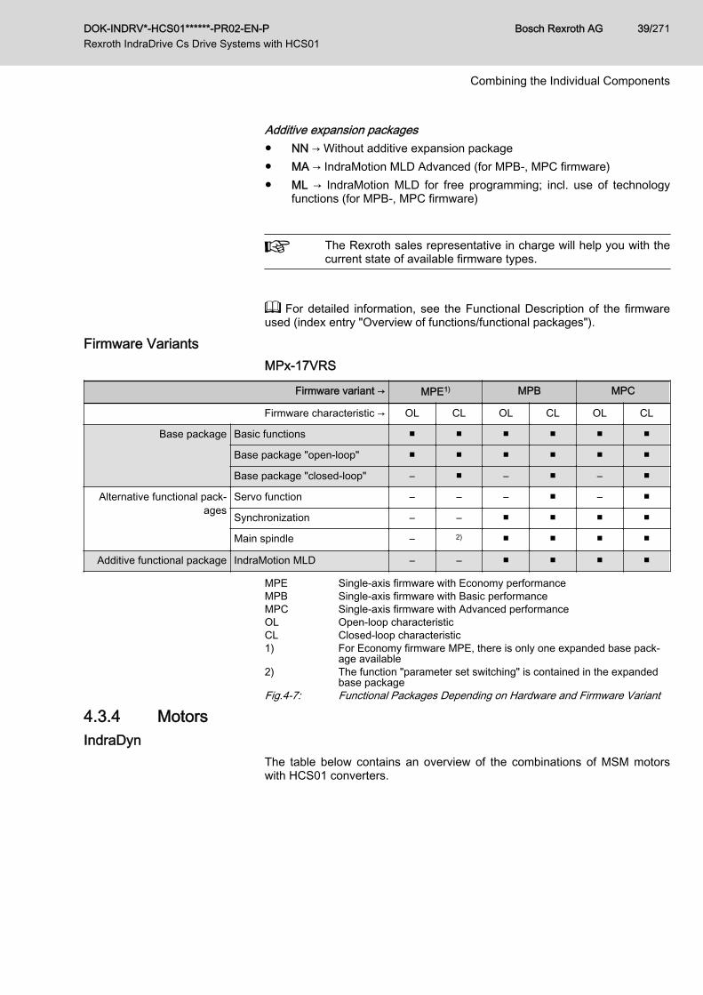
Additive expansion packages● NN → Without additive expansion package● MA → IndraMotion MLD Advanced (for MPB-, MPC firmware)● ML → IndraMotion MLD for free programming; incl. use of technology
functions (for MPB-, MPC firmware)
The Rexroth sales representative in charge will help you with thecurrent state of available firmware types.
For detailed information, see the Functional Description of the firmwareused (index entry "Overview of functions/functional packages").
Firmware VariantsMPx-17VRS
Firmware variant → MPE1) MPB MPC
Firmware characteristic → OL CL OL CL OL CL
Base package Basic functions ■ ■ ■ ■ ■ ■
Base package "open-loop" ■ ■ ■ ■ ■ ■
Base package "closed-loop" – ■ – ■ – ■
Alternative functional pack‐ages
Servo function – – – ■ – ■
Synchronization – – ■ ■ ■ ■
Main spindle – 2) ■ ■ ■ ■
Additive functional package IndraMotion MLD – – ■ ■ ■ ■
MPE Single-axis firmware with Economy performanceMPB Single-axis firmware with Basic performanceMPC Single-axis firmware with Advanced performanceOL Open-loop characteristicCL Closed-loop characteristic1) For Economy firmware MPE, there is only one expanded base pack‐
age available2) The function "parameter set switching" is contained in the expanded
base packageFig.4-7: Functional Packages Depending on Hardware and Firmware Variant
4.3.4 MotorsIndraDyn
The table below contains an overview of the combinations of MSM motorswith HCS01 converters.
DOK-INDRV*-HCS01******-PR02-EN-P Rexroth IndraDrive Cs Drive Systems with HCS01
Bosch Rexroth AG 39/271
Combining the Individual Components
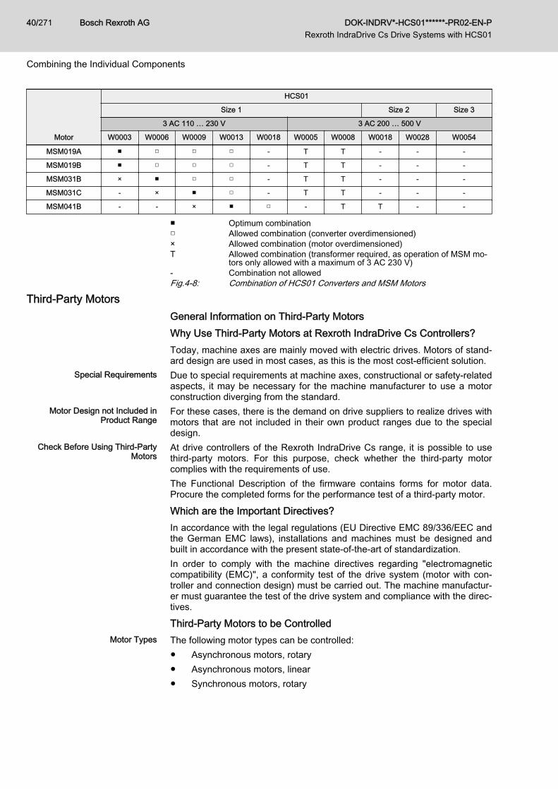
Motor
HCS01
Size 1 Size 2 Size 3
3 AC 110 … 230 V 3 AC 200 … 500 V
W0003 W0006 W0009 W0013 W0018 W0005 W0008 W0018 W0028 W0054
MSM019A ■ □ □ □ - T T - - -
MSM019B ■ □ □ □ - T T - - -
MSM031B × ■ □ □ - T T - - -
MSM031C - × ■ □ - T T - - -
MSM041B - - × ■ □ - T T - -
■ Optimum combination□ Allowed combination (converter overdimensioned)× Allowed combination (motor overdimensioned)T Allowed combination (transformer required, as operation of MSM mo‐
tors only allowed with a maximum of 3 AC 230 V)- Combination not allowedFig.4-8: Combination of HCS01 Converters and MSM Motors
Third-Party MotorsGeneral Information on Third-Party MotorsWhy Use Third-Party Motors at Rexroth IndraDrive Cs Controllers?Today, machine axes are mainly moved with electric drives. Motors of stand‐ard design are used in most cases, as this is the most cost-efficient solution.
Special Requirements Due to special requirements at machine axes, constructional or safety-relatedaspects, it may be necessary for the machine manufacturer to use a motorconstruction diverging from the standard.
Motor Design not Included inProduct Range
For these cases, there is the demand on drive suppliers to realize drives withmotors that are not included in their own product ranges due to the specialdesign.
Check Before Using Third-PartyMotors
At drive controllers of the Rexroth IndraDrive Cs range, it is possible to usethird-party motors. For this purpose, check whether the third-party motorcomplies with the requirements of use.The Functional Description of the firmware contains forms for motor data.Procure the completed forms for the performance test of a third-party motor.
Which are the Important Directives?In accordance with the legal regulations (EU Directive EMC 89/336/EEC andthe German EMC laws), installations and machines must be designed andbuilt in accordance with the present state-of-the-art of standardization.In order to comply with the machine directives regarding "electromagneticcompatibility (EMC)", a conformity test of the drive system (motor with con‐troller and connection design) must be carried out. The machine manufactur‐er must guarantee the test of the drive system and compliance with the direc‐tives.
Third-Party Motors to be ControlledMotor Types The following motor types can be controlled:
● Asynchronous motors, rotary● Asynchronous motors, linear● Synchronous motors, rotary
Bosch Rexroth AG DOK-INDRV*-HCS01******-PR02-EN-P Rexroth IndraDrive Cs Drive Systems with HCS01
40/271
Combining the Individual Components
● Synchronous motors, linearThese motors can be operated within the scope of the technical data of theselected Rexroth IndraDrive Cs controller. If motors have been provided witha holding brake, it should be controlled via the drive controller. Make surethat the relevant technical data of the motor holding brake are complying withthose of the holding brake output!
For third-party motors Rexroth, as a matter of principle, does notassume the guarantee for the power data at the motor shaft!
Synchronous Motors For synchronous motors with motor encoder, the commutation offset must beset during commissioning. The drive firmware provides several methods fordetermining this offset so that it is possible to determine the value for differentmotor characteristics.
Observe the restrictions in conjunction with the commutation off‐set determination when using synchronous motors! See firmwaredocumentation, chapter "Drive Control", "Commutation Setting".Possibly available reluctance property cannot be used for syn‐chronous third-party motors! For third-party motors, it is impossi‐ble to determine fail-safe motor parameter values for using the re‐luctance property. The respective bit of "P‑0‑4014, Type of con‐struction of motor" therefore mustn't be set!
Requirements on Third-Party MotorsGeneral InformationFor successful and fail-safe use of a third-party motor, check● whether the third-party motor to be controlled satisfies the voltage loads● which drive controller is suitable due to the motor torques to be deliv‐
ered● whether the third-party motor has the required minimum inductance● whether the motor can be protected against inadmissible temperature
rise in the case of overload (temperature evaluation)● whether the mounted position measuring system can be evaluated by
the drive controller or which position measuring system can be selectedfor kit motors
Voltage Load of the Third-Party MotorThe voltage load of the insulation system of a motor occurring in practical ap‐plication is mainly influenced by the following characteristics:● The output variables of the drive controller which is used (feed the trans‐
mission distance)● Cable parameters depending on cable design and length (determine the
properties of the transmission distance, such as the attenuation)● The motor design regarding capacitive and inductive properties (form
the end of the transmission distance)As a result of the variables, the insulation system of the third-party motor, asregards voltage, is loaded by the following values:● Periodic peak voltage Upp and● Voltage change dv/dt
DOK-INDRV*-HCS01******-PR02-EN-P Rexroth IndraDrive Cs Drive Systems with HCS01
Bosch Rexroth AG 41/271
Combining the Individual Components
The occurring periodic peak voltages at the motor terminals are caused byreflections at the motor cable end. The insulation of the motor is thereby loa‐ded with a higher peak voltage than the one occurring at the output of thepower section.
Determine the occurring voltage load at the terminals of the third-party motor in the application with all involved components.
Using the HMF Motor Filter Use voltage-reducing components (e.g. motor filter HMF), if one of the follow‐ing criteria applies:● Allowed voltage change (dv/dt) of third-party motor: < 5 kV/μs● With mains voltage 3 AC 230 V … 500 V:
Allowed periodic peak voltage (crest value) of third-party motor betweenphase-phase and phase-housing: < 1,500 V
● With mains voltage up to 3 AC 230 V:Allowed periodic peak voltage (crest value) of third-party motor betweenphase-phase and phase-housing: < 850 V(To operate motors which do not require any voltage-reducing compo‐nents at this mains voltage, the switch-on threshold of the braking resis‐tor must be reduced to DC 430 V for devices with the mains connectionvoltage identifier "03"!)
● The voltage change (dv/dt) and periodic peak voltage (Upp) at the motorterminals are influenced by the length and the electrical properties of themotor cable:– The longer the motor cable, the higher the degree of voltage over‐
shoot (periodic peak voltage) at the motor-side cable end. With acable length of approx. 25 m and more, the maximum periodicpeak voltage occurs. Further voltage increase is not to be expectedeven with longer cables.
– With cable lengths of less than 15 m, the periodic peak voltage isreduced, depending on the length and as compared to the speci‐fied maximum value, down to the DC bus voltage value.
Apart from the nominal current IN, especially take the maximumallowed switching frequency of the power output stage (fs) into ac‐count with which the motor filter HMF may be operated.Verify the success of the voltage-reducing measures by measur‐ing the voltage at the motor terminals. Use an isolated measuringdevice!
Minimum Inductance of Third-Party MotorDepending on the drive controller used, the motor has to have a minimumvalue for inductance. The actually available inductance of a motor can bemeasured directly between two motor terminals by means of an inductancemeasuring bridge. The measurement has to be made for a complete motorwired for normal operation but not yet connected. During the measurement,one motor terminal remains open! For asynchronous motors, the measuredvalue can only be used if the rotor doesn't have closed slots!
Bosch Rexroth AG DOK-INDRV*-HCS01******-PR02-EN-P Rexroth IndraDrive Cs Drive Systems with HCS01
42/271
Combining the Individual Components
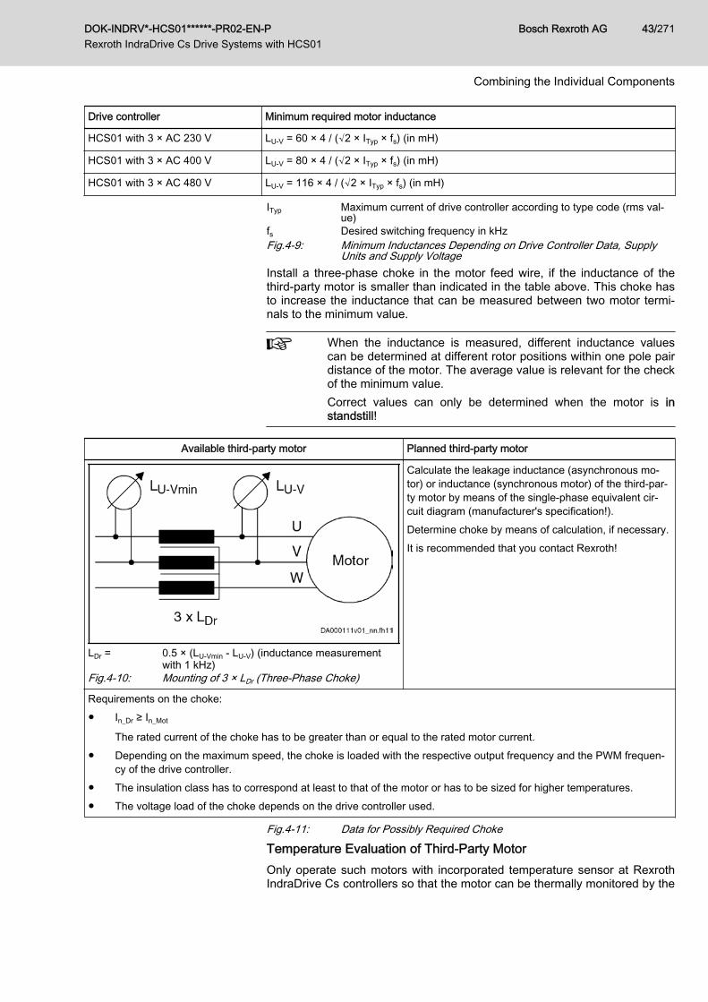
Drive controller Minimum required motor inductance
HCS01 with 3 × AC 230 V LU-V = 60 × 4 / (√2 × ITyp × fs) (in mH)
HCS01 with 3 × AC 400 V LU-V = 80 × 4 / (√2 × ITyp × fs) (in mH)
HCS01 with 3 × AC 480 V LU-V = 116 × 4 / (√2 × ITyp × fs) (in mH)
ITyp Maximum current of drive controller according to type code (rms val‐ue)
fs Desired switching frequency in kHzFig.4-9: Minimum Inductances Depending on Drive Controller Data, Supply
Units and Supply VoltageInstall a three-phase choke in the motor feed wire, if the inductance of thethird-party motor is smaller than indicated in the table above. This choke hasto increase the inductance that can be measured between two motor termi‐nals to the minimum value.
When the inductance is measured, different inductance valuescan be determined at different rotor positions within one pole pairdistance of the motor. The average value is relevant for the checkof the minimum value.Correct values can only be determined when the motor is instandstill!
Available third-party motor Planned third-party motor
LDr = 0.5 × (LU-Vmin - LU-V) (inductance measurementwith 1 kHz)
Fig.4-10: Mounting of 3 × LDr (Three-Phase Choke)
Calculate the leakage inductance (asynchronous mo‐tor) or inductance (synchronous motor) of the third-par‐ty motor by means of the single-phase equivalent cir‐cuit diagram (manufacturer's specification!).Determine choke by means of calculation, if necessary.It is recommended that you contact Rexroth!
Requirements on the choke:● In_Dr ≥ In_Mot
The rated current of the choke has to be greater than or equal to the rated motor current.● Depending on the maximum speed, the choke is loaded with the respective output frequency and the PWM frequen‐
cy of the drive controller.● The insulation class has to correspond at least to that of the motor or has to be sized for higher temperatures.● The voltage load of the choke depends on the drive controller used.
Fig.4-11: Data for Possibly Required Choke
Temperature Evaluation of Third-Party MotorOnly operate such motors with incorporated temperature sensor at RexrothIndraDrive Cs controllers so that the motor can be thermally monitored by the
DOK-INDRV*-HCS01******-PR02-EN-P Rexroth IndraDrive Cs Drive Systems with HCS01
Bosch Rexroth AG 43/271
Combining the Individual Components
drive controller and protected against destruction by too high temperaturerise (see "P‑0‑0512, Temperature sensor").When, in exceptional cases, you would like to operate third-party motors with‐out temperature sensor at Rexroth IndraDrive Cs controllers, you must deter‐mine the thermal time constants of motor housing (P‑0‑4035) and motorwinding (P‑0‑4034, P‑0‑4037). By means of its temperature model, the firm‐ware can correctly reflect the cooling situation of the motor.
In case the motor housing or fan is dirty, this worsens the coolingsituation of the motor and protection against thermal overload istherefore insufficient!
Requirements on the Encoder of the Third-Party MotorMotor Encoder of Asynchronous Third-Party MotorAsynchronous motors can also be controlled by Rexroth IndraDrive Cs con‐trollers in "open-loop" operation (without motor encoder). In "closed-loop" op‐eration (with motor encoder), a relative measuring system is sufficient forasynchronous motors.
Motor Encoder of Synchronous Third-Party MotorFor fail-safe drives with synchronous third-party motors at RexrothIndraDrive Cs controllers, the following possible combinations or restrictionshave to be taken into account when selecting the measuring system:
Drive range Motor measuring system Synchronous third-partymotor
Rexroth IndraDrive CsAbsolute ■
Relative □
■ Advantageous combination□ Combination is possible (restrictions specific to application), commis‐
sioning may be more complicated!Fig.4-12: Possible Combinations of Synchronous Third-Party Motor and Motor
Measuring System
The drive controller can evaluate measuring systems as motorencoder when they are contained in "P‑0‑0074, Encoder type 1(motor encoder)".For information on absolute and relative measuring systems, seesection "Measuring Systems" of firmware documentation!
Motor Encoder Resolver - Notes on SelectionResolvers must first be checked as to whether they are suited as motor en‐coders. To check whether they can be evaluated by the drive controllers, thefollowing resolver data are required:● Data of resolver system to be compared must be available at 8 kHz● Ratio● Current consumption● DC resistance of stator● Number of poles● Phase shift
Bosch Rexroth AG DOK-INDRV*-HCS01******-PR02-EN-P Rexroth IndraDrive Cs Drive Systems with HCS01
44/271
Combining the Individual Components
By means of the resolver data, check whether the supply voltage of the en‐coder interface and the signal levels of the encoder tracks are sufficient.
Notes on Selection and CommissioningSelecting the Controller as Regards Continuous CurrentThe drive controller required for the respective motor is determined by com‐paring the motor data to the device data.
The continuous current of the drive controller should be greaterthan the continuous current of the motor.The continuous power of the drive controller must be greater thanthe required average power!
Selecting the Connection TechniqueFor the available power cables and encoder cables, see documentation"Rexroth Connection Cables IndraDrive and IndraDyn".
Notes on Commissioning
For further information, notes on commissioning and supportingdocuments (e.g., forms for entering the required data) see firm‐ware documentation.
4.3.5 CablesMotor Power Cables
SelectionHow to select a suitable motor power cable:See documentation "Rexroth Connection Cables IndraDrive and IndraDyn"(R911322949).
DOK-INDRV*-HCS01******-PR02-EN-P Rexroth IndraDrive Cs Drive Systems with HCS01
Bosch Rexroth AG 45/271
Combining the Individual Components
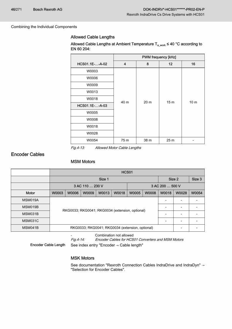
Allowed Cable LengthsAllowed Cable Lengths at Ambient Temperature Ta_work ≤ 40 °C according toEN 60 204:
HCS01.1E-…-A-02
PWM frequency [kHz]
4 8 12 16
W0003
40 m 20 m 15 m 10 m
W0006
W0009
W0013
W0018
HCS01.1E-…-A-03
W0005
W0008
W0018
W0028
W0054 75 m 38 m 25 m -
Fig.4-13: Allowed Motor Cable Lengths
Encoder CablesMSM Motors
HCS01
Size 1 Size 2 Size 3
3 AC 110 … 230 V 3 AC 200 … 500 V
Motor W0003 W0006 W0009 W0013 W0018 W0005 W0008 W0018 W0028 W0054
MSM019A
RKG0033; RKG0041; RKG0034 (extension, optional)
- - -
MSM019B - - -
MSM031B - - -
MSM031C - - -
MSM041B RKG0033; RKG0041; RKG0034 (extension, optional) - -
- Combination not allowedFig.4-14: Encoder Cables for HCS01 Converters and MSM Motors
Encoder Cable Length See index entry "Encoder → Cable length"
MSK MotorsSee documentation "Rexroth Connection Cables IndraDrive and IndraDyn" →"Selection for Encoder Cables".
Bosch Rexroth AG DOK-INDRV*-HCS01******-PR02-EN-P Rexroth IndraDrive Cs Drive Systems with HCS01
46/271
Combining the Individual Components
4.4 Installation Conditions4.4.1 Ambient and Operating Conditions
Lethal electric shock by live parts with morethan 50 V!
WARNING
Exclusively operate the device● with plugged on connectors (even if there haven't been any lines con‐
nected to the connectors) and● with connected equipment grounding conductor!
Control Cabinet The devices of the Rexroth IndraDrive Cs product range, as well as their ad‐ditional components (except for some braking resistors), must be mounted incontrol cabinets.Check that the ambient and operating conditions, in particular the controlcabinet temperature, are complied with by calculating the heat levels in thecontrol cabinet. Afterwards, make the corresponding measurements to findout that the ambient and operating conditions have actually been compliedwith. In the technical data of the individual components, the power dissipationis indicated as an important input value for calculating the heat levels.Ambient and Operating Conditions
Description Symbol Unit Value
Conductive dirt contamination Not allowed(You can protect the devices against conductive dirt
contamination, for example by mounting them in con‐trol cabinets of the degree of protection IP54 in ac‐
cordance with IEC529.)
Degree of protection (IEC529) IP20
Use in the scope of CSA / UL For use in NFPA 79 Applications only.
Temperature during storage See chapter "Storage of the Components"
Temperature during transport See chapter "Transport of the Components"
Allowed mounting positionDefinition of mounting positions: See index en‐try "Mounting positions"
G1
Installation altitude hnenn m 1000
Ambient temperature range Ta_work °C 0 … 40
DOK-INDRV*-HCS01******-PR02-EN-P Rexroth IndraDrive Cs Drive Systems with HCS01
Bosch Rexroth AG 47/271
Combining the Individual Components
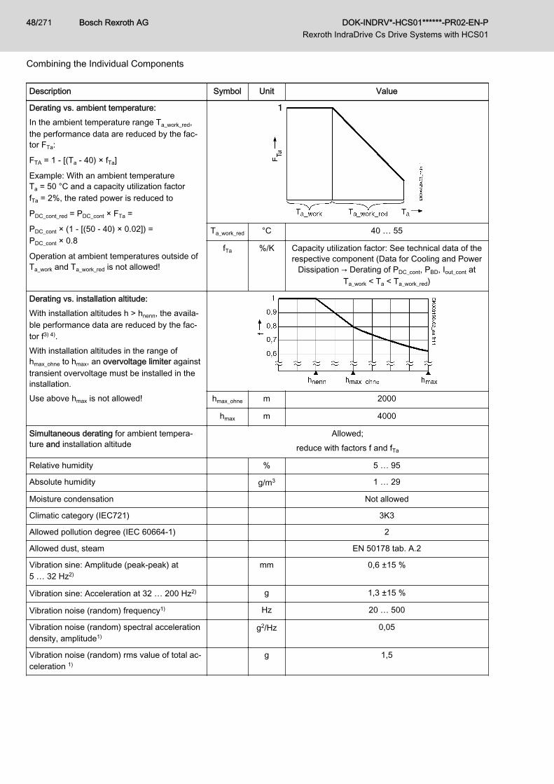
Description Symbol Unit Value
Derating vs. ambient temperature:In the ambient temperature range Ta_work_red,the performance data are reduced by the fac‐tor FTa:
FTA = 1 - [(Ta - 40) × fTa]
Example: With an ambient temperatureTa = 50 °C and a capacity utilization factorfTa = 2%, the rated power is reduced to
PDC_cont_red = PDC_cont × FTa =
PDC_cont × (1 - [(50 - 40) × 0.02]) =PDC_cont × 0.8
Operation at ambient temperatures outside ofTa_work and Ta_work_red is not allowed!
Ta_work_red °C 40 … 55
fTa %/K Capacity utilization factor: See technical data of therespective component (Data for Cooling and Power
Dissipation → Derating of PDC_cont, PBD, Iout_cont atTa_work < Ta < Ta_work_red)
Derating vs. installation altitude:With installation altitudes h > hnenn, the availa‐ble performance data are reduced by the fac‐tor f3) 4).With installation altitudes in the range ofhmax_ohne to hmax, an overvoltage limiter againsttransient overvoltage must be installed in theinstallation.Use above hmax is not allowed! hmax_ohne m 2000
hmax m 4000
Simultaneous derating for ambient tempera‐ture and installation altitude
Allowed;reduce with factors f and fTa
Relative humidity % 5 … 95
Absolute humidity g/m3 1 … 29
Moisture condensation Not allowed
Climatic category (IEC721) 3K3
Allowed pollution degree (IEC 60664‑1) 2
Allowed dust, steam EN 50178 tab. A.2
Vibration sine: Amplitude (peak-peak) at5 … 32 Hz2)
mm 0,6 ±15 %
Vibration sine: Acceleration at 32 … 200 Hz2) g 1,3 ±15 %
Vibration noise (random) frequency1) Hz 20 … 500
Vibration noise (random) spectral accelerationdensity, amplitude1)
g2/Hz 0,05
Vibration noise (random) rms value of total ac‐celeration 1)
g 1,5
Bosch Rexroth AG DOK-INDRV*-HCS01******-PR02-EN-P Rexroth IndraDrive Cs Drive Systems with HCS01
48/271
Combining the Individual Components
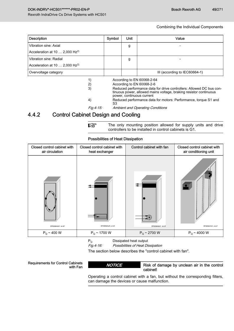
Description Symbol Unit Value
Vibration sine: Axial
Acceleration at 10 … 2,000 Hz2)
g -
Vibration sine: Radial
Acceleration at 10 … 2,000 Hz2)
g -
Overvoltage category III (according to IEC60664-1)
1) According to EN 60068-2-642) According to EN 60068-2-63) Reduced performance data for drive controllers: Allowed DC bus con‐
tinuous power, allowed mains voltage, braking resistor continuouspower, continuous current
4) Reduced performance data for motors: Performance, torque S1 andS3
Fig.4-15: Ambient and Operating Conditions
4.4.2 Control Cabinet Design and Cooling
The only mounting position allowed for supply units and drivecontrollers to be installed in control cabinets is G1.
Possibilities of Heat Dissipation
Closed control cabinet withair circulation
Closed control cabinet withheat exchanger
Control cabinet with fan Closed control cabinet withair conditioning unit
PQ ~ 400 W PQ ~ 1700 W PQ ~ 2700 W PQ ~ 4000 W
PQ Dissipated heat outputFig.4-16: Possibilities of Heat DissipationThe section below describes the "control cabinet with fan".
Requirements for Control Cabinetswith Fan Risk of damage by unclean air in the control
cabinet!NOTICE
Operating a control cabinet with a fan, but without the corresponding filters,can damage the devices or cause malfunction.
DOK-INDRV*-HCS01******-PR02-EN-P Rexroth IndraDrive Cs Drive Systems with HCS01
Bosch Rexroth AG 49/271
Combining the Individual Components
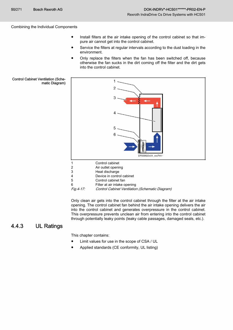
● Install filters at the air intake opening of the control cabinet so that im‐pure air cannot get into the control cabinet.
● Service the filters at regular intervals according to the dust loading in theenvironment.
● Only replace the filters when the fan has been switched off, becauseotherwise the fan sucks in the dirt coming off the filter and the dirt getsinto the control cabinet.
Control Cabinet Ventilation (Sche‐
matic Diagram)
1 Control cabinet2 Air outlet opening3 Heat discharge4 Device in control cabinet5 Control cabinet fan6 Filter at air intake openingFig.4-17: Control Cabinet Ventilation (Schematic Diagram) Only clean air gets into the control cabinet through the filter at the air intakeopening. The control cabinet fan behind the air intake opening delivers the airinto the control cabinet and generates overpressure in the control cabinet.This overpressure prevents unclean air from entering into the control cabinetthrough potentially leaky points (leaky cable passages, damaged seals, etc.).
4.4.3 UL RatingsThis chapter contains:● Limit values for use in the scope of CSA / UL● Applied standards (CE conformity, UL listing)
Bosch Rexroth AG DOK-INDRV*-HCS01******-PR02-EN-P Rexroth IndraDrive Cs Drive Systems with HCS01
50/271
Combining the Individual Components
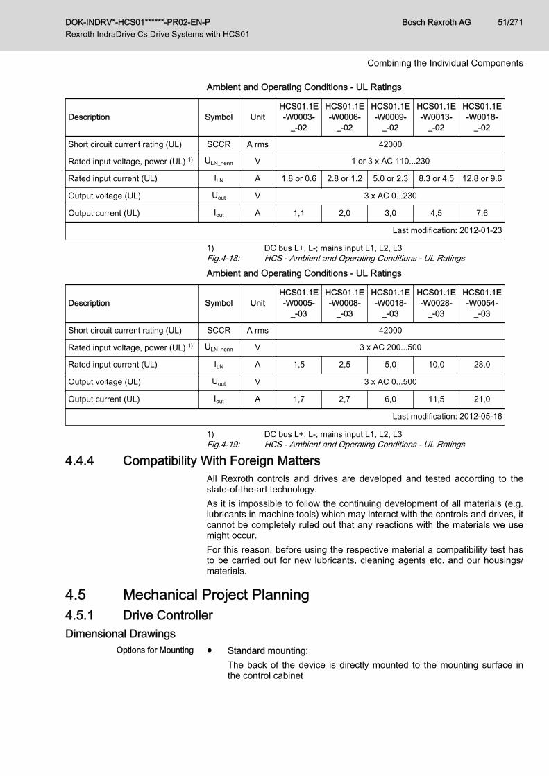
Ambient and Operating Conditions - UL Ratings
Description Symbol UnitHCS01.1E-W0003-
_-02
HCS01.1E-W0006-
_-02
HCS01.1E-W0009-
_-02
HCS01.1E-W0013-
_-02
HCS01.1E-W0018-
_-02
Short circuit current rating (UL) SCCR A rms 42000
Rated input voltage, power (UL) 1) ULN_nenn V 1 or 3 x AC 110...230
Rated input current (UL) ILN A 1.8 or 0.6 2.8 or 1.2 5.0 or 2.3 8.3 or 4.5 12.8 or 9.6
Output voltage (UL) Uout V 3 x AC 0...230
Output current (UL) Iout A 1,1 2,0 3,0 4,5 7,6
Last modification: 2012-01-23
1) DC bus L+, L-; mains input L1, L2, L3Fig.4-18: HCS - Ambient and Operating Conditions - UL RatingsAmbient and Operating Conditions - UL Ratings
Description Symbol UnitHCS01.1E-W0005-
_-03
HCS01.1E-W0008-
_-03
HCS01.1E-W0018-
_-03
HCS01.1E-W0028-
_-03
HCS01.1E-W0054-
_-03
Short circuit current rating (UL) SCCR A rms 42000
Rated input voltage, power (UL) 1) ULN_nenn V 3 x AC 200...500
Rated input current (UL) ILN A 1,5 2,5 5,0 10,0 28,0
Output voltage (UL) Uout V 3 x AC 0...500
Output current (UL) Iout A 1,7 2,7 6,0 11,5 21,0
Last modification: 2012-05-16
1) DC bus L+, L-; mains input L1, L2, L3Fig.4-19: HCS - Ambient and Operating Conditions - UL Ratings
4.4.4 Compatibility With Foreign MattersAll Rexroth controls and drives are developed and tested according to thestate-of-the-art technology.As it is impossible to follow the continuing development of all materials (e.g.lubricants in machine tools) which may interact with the controls and drives, itcannot be completely ruled out that any reactions with the materials we usemight occur.For this reason, before using the respective material a compatibility test hasto be carried out for new lubricants, cleaning agents etc. and our housings/materials.
4.5 Mechanical Project Planning4.5.1 Drive ControllerDimensional Drawings
Options for Mounting ● Standard mounting:The back of the device is directly mounted to the mounting surface inthe control cabinet
DOK-INDRV*-HCS01******-PR02-EN-P Rexroth IndraDrive Cs Drive Systems with HCS01
Bosch Rexroth AG 51/271
Combining the Individual Components
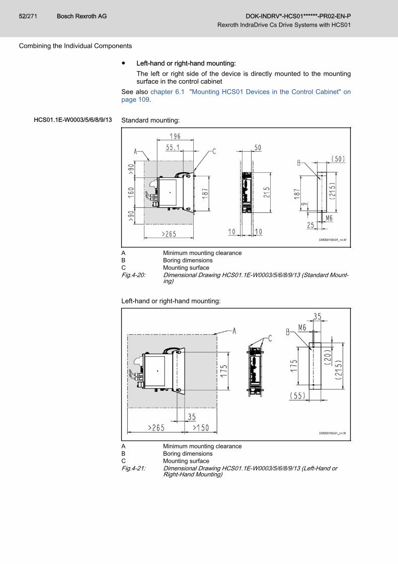
● Left-hand or right-hand mounting:The left or right side of the device is directly mounted to the mountingsurface in the control cabinet
See also chapter 6.1 "Mounting HCS01 Devices in the Control Cabinet" onpage 109.
HCS01.1E-W0003/5/6/8/9/13 Standard mounting:
A Minimum mounting clearanceB Boring dimensionsC Mounting surfaceFig.4-20: Dimensional Drawing HCS01.1E-W0003/5/6/8/9/13 (Standard Mount‐
ing) Left-hand or right-hand mounting:
A Minimum mounting clearanceB Boring dimensionsC Mounting surfaceFig.4-21: Dimensional Drawing HCS01.1E-W0003/5/6/8/9/13 (Left-Hand or
Right-Hand Mounting)
Bosch Rexroth AG DOK-INDRV*-HCS01******-PR02-EN-P Rexroth IndraDrive Cs Drive Systems with HCS01
52/271
Combining the Individual Components
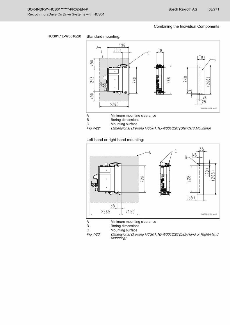
HCS01.1E-W0018/28 Standard mounting:
A Minimum mounting clearanceB Boring dimensionsC Mounting surfaceFig.4-22: Dimensional Drawing HCS01.1E-W0018/28 (Standard Mounting) Left-hand or right-hand mounting:
A Minimum mounting clearanceB Boring dimensionsC Mounting surfaceFig.4-23: Dimensional Drawing HCS01.1E-W0018/28 (Left-Hand or Right-Hand
Mounting)
DOK-INDRV*-HCS01******-PR02-EN-P Rexroth IndraDrive Cs Drive Systems with HCS01
Bosch Rexroth AG 53/271
Combining the Individual Components
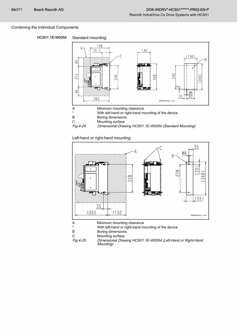
HCS01.1E-W0054 Standard mounting:
A Minimum mounting clearance* With left-hand or right-hand mounting of the deviceB Boring dimensionsC Mounting surfaceFig.4-24: Dimensional Drawing HCS01.1E-W0054 (Standard Mounting) Left-hand or right-hand mounting:
A Minimum mounting clearance* With left-hand or right-hand mounting of the deviceB Boring dimensionsC Mounting surfaceFig.4-25: Dimensional Drawing HCS01.1E-W0054 (Left-Hand or Right-Hand
Mounting)
Bosch Rexroth AG DOK-INDRV*-HCS01******-PR02-EN-P Rexroth IndraDrive Cs Drive Systems with HCS01
54/271
Combining the Individual Components
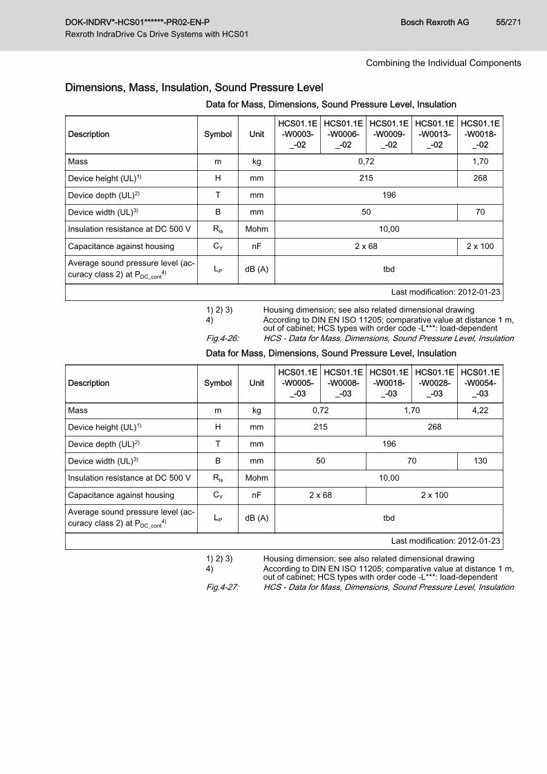
Dimensions, Mass, Insulation, Sound Pressure LevelData for Mass, Dimensions, Sound Pressure Level, Insulation
Description Symbol UnitHCS01.1E-W0003-
_-02
HCS01.1E-W0006-
_-02
HCS01.1E-W0009-
_-02
HCS01.1E-W0013-
_-02
HCS01.1E-W0018-
_-02
Mass m kg 0,72 1,70
Device height (UL)1) H mm 215 268
Device depth (UL)2) T mm 196
Device width (UL)3) B mm 50 70
Insulation resistance at DC 500 V Ris Mohm 10,00
Capacitance against housing CY nF 2 x 68 2 x 100
Average sound pressure level (ac‐curacy class 2) at PDC_cont
4) LP dB (A) tbd
Last modification: 2012-01-23
1) 2) 3) Housing dimension; see also related dimensional drawing4) According to DIN EN ISO 11205; comparative value at distance 1 m,
out of cabinet; HCS types with order code -L***: load-dependentFig.4-26: HCS - Data for Mass, Dimensions, Sound Pressure Level, InsulationData for Mass, Dimensions, Sound Pressure Level, Insulation
Description Symbol UnitHCS01.1E-W0005-
_-03
HCS01.1E-W0008-
_-03
HCS01.1E-W0018-
_-03
HCS01.1E-W0028-
_-03
HCS01.1E-W0054-
_-03
Mass m kg 0,72 1,70 4,22
Device height (UL)1) H mm 215 268
Device depth (UL)2) T mm 196
Device width (UL)3) B mm 50 70 130
Insulation resistance at DC 500 V Ris Mohm 10,00
Capacitance against housing CY nF 2 x 68 2 x 100
Average sound pressure level (ac‐curacy class 2) at PDC_cont
4) LP dB (A) tbd
Last modification: 2012-01-23
1) 2) 3) Housing dimension; see also related dimensional drawing4) According to DIN EN ISO 11205; comparative value at distance 1 m,
out of cabinet; HCS types with order code -L***: load-dependentFig.4-27: HCS - Data for Mass, Dimensions, Sound Pressure Level, Insulation
DOK-INDRV*-HCS01******-PR02-EN-P Rexroth IndraDrive Cs Drive Systems with HCS01
Bosch Rexroth AG 55/271
Combining the Individual Components
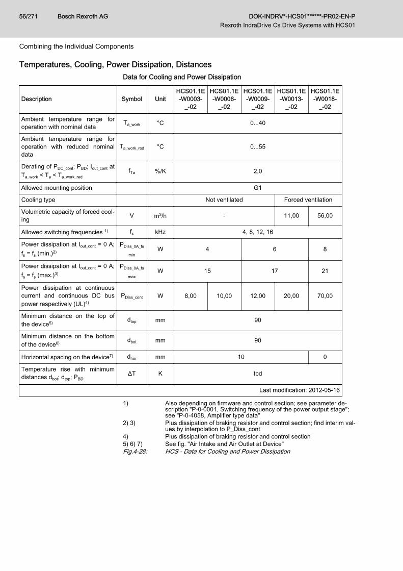
Temperatures, Cooling, Power Dissipation, DistancesData for Cooling and Power Dissipation
Description Symbol UnitHCS01.1E-W0003-
_-02
HCS01.1E-W0006-
_-02
HCS01.1E-W0009-
_-02
HCS01.1E-W0013-
_-02
HCS01.1E-W0018-
_-02
Ambient temperature range foroperation with nominal data Ta_work °C 0...40
Ambient temperature range foroperation with reduced nominaldata
Ta_work_red °C 0...55
Derating of PDC_cont; PBD; Iout_cont atTa_work < Ta < Ta_work_red
fTa %/K 2,0
Allowed mounting position G1
Cooling type Not ventilated Forced ventilation
Volumetric capacity of forced cool‐ing V m3/h - 11,00 56,00
Allowed switching frequencies 1) fs kHz 4, 8, 12, 16
Power dissipation at Iout_cont = 0 A;fs = fs (min.)2)
PDiss_0A_fs
minW 4 6 8
Power dissipation at Iout_cont = 0 A;fs = fs (max.)3)
PDiss_0A_fs
maxW 15 17 21
Power dissipation at continuouscurrent and continuous DC buspower respectively (UL)4)
PDiss_cont W 8,00 10,00 12,00 20,00 70,00
Minimum distance on the top ofthe device5) dtop mm 90
Minimum distance on the bottomof the device6) dbot mm 90
Horizontal spacing on the device7) dhor mm 10 0
Temperature rise with minimumdistances dbot; dtop; PBD
ΔT K tbd
Last modification: 2012-05-16
1) Also depending on firmware and control section; see parameter de‐scription "P‑0‑0001, Switching frequency of the power output stage";see "P‑0‑4058, Amplifier type data"
2) 3) Plus dissipation of braking resistor and control section; find interim val‐ues by interpolation to P_Diss_cont
4) Plus dissipation of braking resistor and control section5) 6) 7) See fig. "Air Intake and Air Outlet at Device"Fig.4-28: HCS - Data for Cooling and Power Dissipation
Bosch Rexroth AG DOK-INDRV*-HCS01******-PR02-EN-P Rexroth IndraDrive Cs Drive Systems with HCS01
56/271
Combining the Individual Components
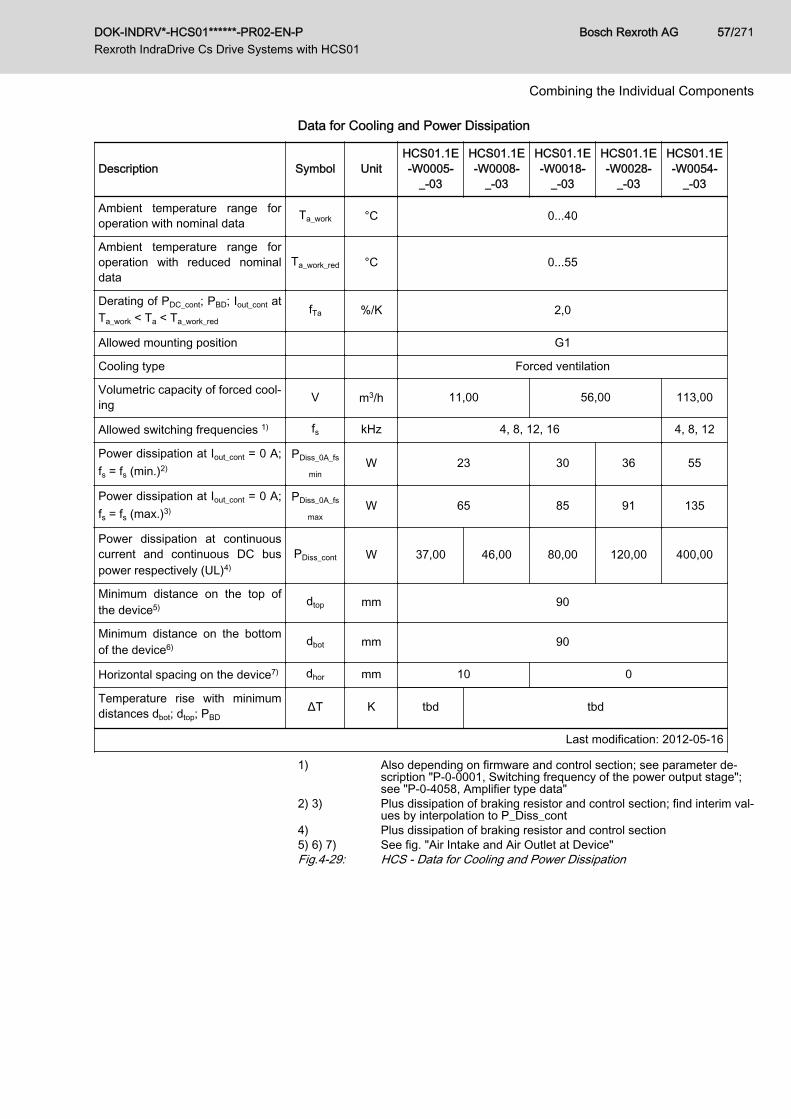
Data for Cooling and Power Dissipation
Description Symbol UnitHCS01.1E-W0005-
_-03
HCS01.1E-W0008-
_-03
HCS01.1E-W0018-
_-03
HCS01.1E-W0028-
_-03
HCS01.1E-W0054-
_-03
Ambient temperature range foroperation with nominal data Ta_work °C 0...40
Ambient temperature range foroperation with reduced nominaldata
Ta_work_red °C 0...55
Derating of PDC_cont; PBD; Iout_cont atTa_work < Ta < Ta_work_red
fTa %/K 2,0
Allowed mounting position G1
Cooling type Forced ventilation
Volumetric capacity of forced cool‐ing V m3/h 11,00 56,00 113,00
Allowed switching frequencies 1) fs kHz 4, 8, 12, 16 4, 8, 12
Power dissipation at Iout_cont = 0 A;fs = fs (min.)2)
PDiss_0A_fs
minW 23 30 36 55
Power dissipation at Iout_cont = 0 A;fs = fs (max.)3)
PDiss_0A_fs
maxW 65 85 91 135
Power dissipation at continuouscurrent and continuous DC buspower respectively (UL)4)
PDiss_cont W 37,00 46,00 80,00 120,00 400,00
Minimum distance on the top ofthe device5) dtop mm 90
Minimum distance on the bottomof the device6) dbot mm 90
Horizontal spacing on the device7) dhor mm 10 0
Temperature rise with minimumdistances dbot; dtop; PBD
ΔT K tbd tbd
Last modification: 2012-05-16
1) Also depending on firmware and control section; see parameter de‐scription "P‑0‑0001, Switching frequency of the power output stage";see "P‑0‑4058, Amplifier type data"
2) 3) Plus dissipation of braking resistor and control section; find interim val‐ues by interpolation to P_Diss_cont
4) Plus dissipation of braking resistor and control section5) 6) 7) See fig. "Air Intake and Air Outlet at Device"Fig.4-29: HCS - Data for Cooling and Power Dissipation
DOK-INDRV*-HCS01******-PR02-EN-P Rexroth IndraDrive Cs Drive Systems with HCS01
Bosch Rexroth AG 57/271
Combining the Individual Components
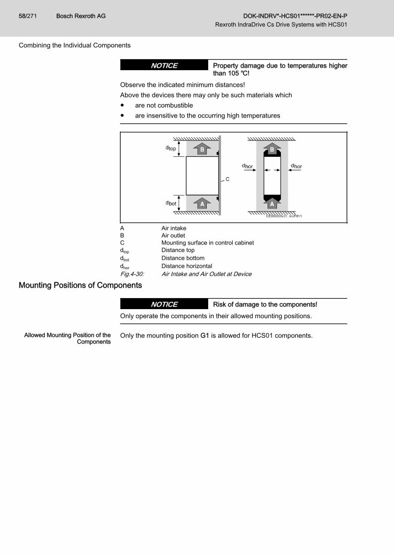
Property damage due to temperatures higherthan 105 ℃!
NOTICE
Observe the indicated minimum distances!Above the devices there may only be such materials which● are not combustible● are insensitive to the occurring high temperatures
A Air intakeB Air outletC Mounting surface in control cabinetdtop Distance topdbot Distance bottomdhor Distance horizontalFig.4-30: Air Intake and Air Outlet at Device
Mounting Positions of Components
Risk of damage to the components!NOTICEOnly operate the components in their allowed mounting positions.
Allowed Mounting Position of theComponents
Only the mounting position G1 is allowed for HCS01 components.
Bosch Rexroth AG DOK-INDRV*-HCS01******-PR02-EN-P Rexroth IndraDrive Cs Drive Systems with HCS01
58/271
Combining the Individual Components
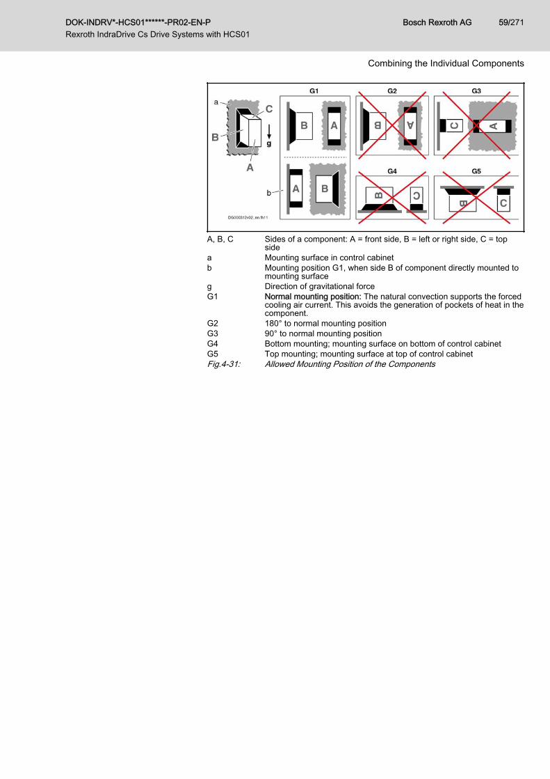
A, B, C Sides of a component: A = front side, B = left or right side, C = topside
a Mounting surface in control cabinetb Mounting position G1, when side B of component directly mounted to
mounting surfaceg Direction of gravitational forceG1 Normal mounting position: The natural convection supports the forced
cooling air current. This avoids the generation of pockets of heat in thecomponent.
G2 180° to normal mounting positionG3 90° to normal mounting positionG4 Bottom mounting; mounting surface on bottom of control cabinetG5 Top mounting; mounting surface at top of control cabinetFig.4-31: Allowed Mounting Position of the Components
DOK-INDRV*-HCS01******-PR02-EN-P Rexroth IndraDrive Cs Drive Systems with HCS01
Bosch Rexroth AG 59/271
Combining the Individual Components
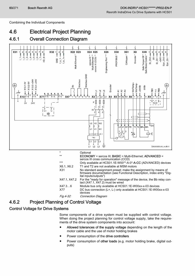
4.6 Electrical Project Planning4.6.1 Overall Connection Diagram
* Optional** ECONOMY = sercos III; BASIC = Multi-Ethernet; ADVANCED =
sercos III cross communication (CCD)*** Only available at HCS01.1E-W00**-A-0*-A-CC (ADVANCED) devicesX6.1, X6.2 T1 and T2 are not available at MSM motorsX31 No standard assignment preset; make the assignment by means of
firmware documentation (see Functional Description, index entry "Dig‐ital inputs/outputs")
X47.1, X47.2 For the "ready for operation" message of the device, the Bb relay con‐tact (X47.1, X47.2) must be wired
X47.3…6 Module bus only available at HCS01.1E-W00xx-x-03 devicesX77 DC bus connection (L+, L-) only available at HCS01.1E‑W00xx‑x‑03
devicesFig.4-32: Connection Diagram
4.6.2 Project Planning of Control VoltageControl Voltage for Drive Systems
Some components of a drive system must be supplied with control voltage.When doing the project planning for control voltage supply, take the require‐ments of the drive system components into account:● Allowed tolerances of the supply voltage depending on the length of the
motor cable and the use of motor holding brakes● Power consumption of the drive controllers● Power consumption of other loads (e.g. motor holding brake, digital out‐
puts)
Bosch Rexroth AG DOK-INDRV*-HCS01******-PR02-EN-P Rexroth IndraDrive Cs Drive Systems with HCS01
60/271
Combining the Individual Components
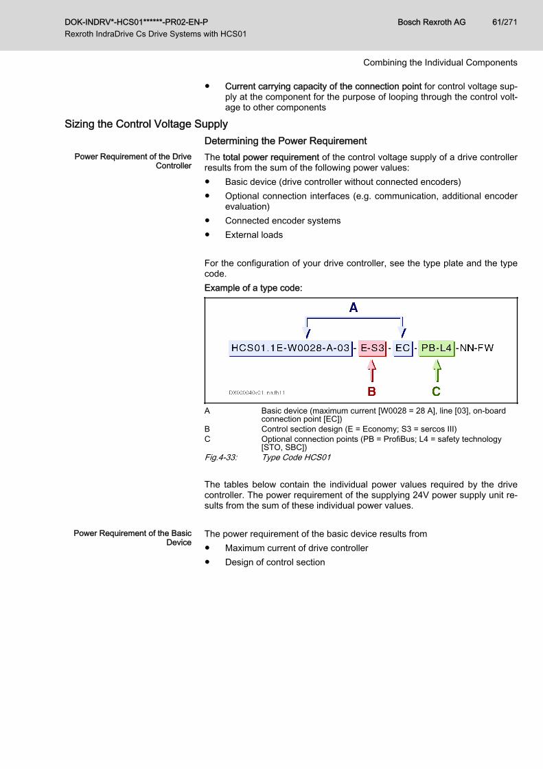
● Current carrying capacity of the connection point for control voltage sup‐ply at the component for the purpose of looping through the control volt‐age to other components
Sizing the Control Voltage SupplyDetermining the Power Requirement
Power Requirement of the DriveController
The total power requirement of the control voltage supply of a drive controllerresults from the sum of the following power values:● Basic device (drive controller without connected encoders)● Optional connection interfaces (e.g. communication, additional encoder
evaluation)● Connected encoder systems● External loads For the configuration of your drive controller, see the type plate and the typecode.Example of a type code:
A Basic device (maximum current [W0028 = 28 A], line [03], on-boardconnection point [EC])
B Control section design (E = Economy; S3 = sercos III)C Optional connection points (PB = ProfiBus; L4 = safety technology
[STO, SBC])Fig.4-33: Type Code HCS01 The tables below contain the individual power values required by the drivecontroller. The power requirement of the supplying 24V power supply unit re‐sults from the sum of these individual power values.
Power Requirement of the BasicDevice
The power requirement of the basic device results from● Maximum current of drive controller● Design of control section
DOK-INDRV*-HCS01******-PR02-EN-P Rexroth IndraDrive Cs Drive Systems with HCS01
Bosch Rexroth AG 61/271
Combining the Individual Components
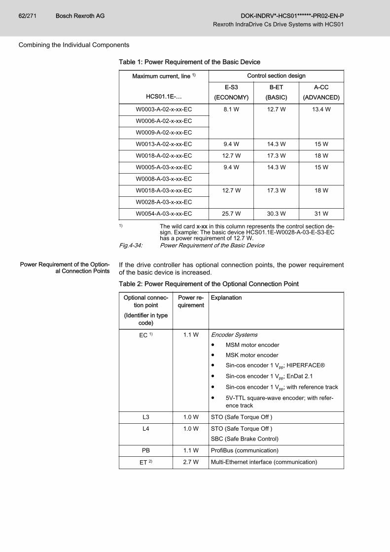
Table 1: Power Requirement of the Basic Device
Maximum current, line 1)
HCS01.1E-…
Control section design
E-S3(ECONOMY)
B-ET(BASIC)
A-CC(ADVANCED)
W0003-A-02-x-xx-EC 8.1 W 12.7 W 13.4 W
W0006-A-02-x-xx-EC
W0009-A-02-x-xx-EC
W0013-A-02-x-xx-EC 9.4 W 14.3 W 15 W
W0018-A-02-x-xx-EC 12.7 W 17.3 W 18 W
W0005-A-03-x-xx-EC 9.4 W 14.3 W 15 W
W0008-A-03-x-xx-EC
W0018-A-03-x-xx-EC 12.7 W 17.3 W 18 W
W0028-A-03-x-xx-EC
W0054-A-03-x-xx-EC 25.7 W 30.3 W 31 W
1) The wild card x-xx in this column represents the control section de‐sign. Example: The basic device HCS01.1E‑W0028-A-03-E-S3-EChas a power requirement of 12.7 W.
Fig.4-34: Power Requirement of the Basic Device
Power Requirement of the Option‐al Connection Points
If the drive controller has optional connection points, the power requirementof the basic device is increased.Table 2: Power Requirement of the Optional Connection Point
Optional connec‐tion point
(Identifier in typecode)
Power re‐quirement
Explanation
EC 1) 1.1 W Encoder Systems● MSM motor encoder● MSK motor encoder● Sin-cos encoder 1 Vpp; HIPERFACE®
● Sin-cos encoder 1 Vpp; EnDat 2.1
● Sin-cos encoder 1 Vpp; with reference track
● 5V-TTL square-wave encoder; with refer‐ence track
L3 1.0 W STO (Safe Torque Off )
L4 1.0 W STO (Safe Torque Off )SBC (Safe Brake Control)
PB 1.1 W ProfiBus (communication)
ET 2) 2.7 W Multi-Ethernet interface (communication)
Bosch Rexroth AG DOK-INDRV*-HCS01******-PR02-EN-P Rexroth IndraDrive Cs Drive Systems with HCS01
62/271
Combining the Individual Components
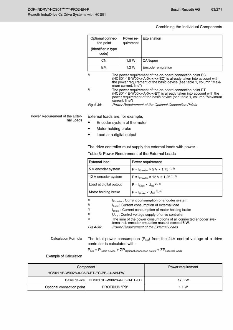
Optional connec‐tion point
(Identifier in typecode)
Power re‐quirement
Explanation
CN 1.5 W CANopen
EM 1.2 W Encoder emulation
1) The power requirement of the on-board connection point EC(HCS01-1E-W00xx-A-0x-x-xx-EC) is already taken into account withthe power requirement of the basic device (see table 1, column "Maxi‐mum current, line")
2) The power requirement of the on-board connection point ET(HCS01-1E-W00xx-A-0x-x-ET) is already taken into account with thepower requirement of the basic device (see table 1, column "Maximumcurrent, line")
Fig.4-35: Power Requirement of the Optional Connection Points
Power Requirement of the Exter‐nal Loads
External loads are, for example,● Encoder system of the motor● Motor holding brake● Load at a digital output The drive controller must supply the external loads with power.Table 3: Power Requirement of the External Loads
External load Power requirement
5 V encoder system P = IEncoder × 5 V × 1.75 1), 5)
12 V encoder system P = IEncoder × 12 V × 1.25 1), 5)
Load at digital output P = ILoad × UN3 2), 4)
Motor holding brake P = IBrake × UN3 3), 4)
1) IEncoder : Current consumption of encoder system2) ILoad : Current consumption of external load3) IBrake : Current consumption of motor holding brake4) UN3 : Control voltage supply of drive controller5) The sum of the power consumptions of all connected encoder sys‐
tems incl. encoder emulation mustn't exceed 6 W.Fig.4-36: Power Requirement of the External Loads
Calculation Formula The total power consumption (PN3) from the 24V control voltage of a drivecontroller is calculated with:PN3 = PBasic device + ΣPOptional connection points + ΣPExternal loads
Example of Calculation
ComponentHCS01.1E-W0028-A-03-B-ET-EC-PB-L4-NN-FW
Power requirement
Basic device HCS01.1E-W0028-A-03-B-ET-EC 17.3 W
Optional connection point PROFIBUS "PB" 1.1 W
DOK-INDRV*-HCS01******-PR02-EN-P Rexroth IndraDrive Cs Drive Systems with HCS01
Bosch Rexroth AG 63/271
Combining the Individual Components
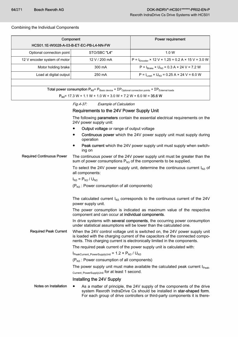
ComponentHCS01.1E-W0028-A-03-B-ET-EC-PB-L4-NN-FW
Power requirement
Optional connection point STO/SBC "L4" 1.0 W
12 V encoder system of motor 12 V / 200 mA P = IEncoder × 12 V × 1.25 = 0.2 A × 15 V = 3.0 W
Motor holding brake 300 mA P = IBrake × UN3 = 0.3 A × 24 V = 7.2 W
Load at digital output 250 mA P = ILoad × UN3 = 0.25 A × 24 V = 6.0 W
Total power consumption PN3= PBasic device + ΣPOptional connection points + ΣPExternal loads
PN3= 17.3 W + 1.1 W + 1.0 W + 3.0 W + 7.2 W + 6.0 W = 35.6 W
Fig.4-37: Example of Calculation
Requirements to the 24V Power Supply UnitThe following parameters contain the essential electrical requirements on the24V power supply unit:● Output voltage or range of output voltage● Continuous power which the 24V power supply unit must supply during
operation● Peak current which the 24V power supply unit must supply when switch‐
ing onRequired Continuous Power The continuous power of the 24V power supply unit must be greater than the
sum of power consumptions PN3 of the components to be supplied.To select the 24V power supply unit, determine the continuous current IN3 ofall components:IN3 = PN3 / UN3
(PN3 : Power consumption of all components) The calculated current IN3 corresponds to the continuous current of the 24Vpower supply unit.The power consumption is indicated as maximum value of the respectivecomponent and can occur at individual components.In drive systems with several components, the occurring power consumptionunder statistical assumptions will be lower than the calculated one.
Required Peak Current When the 24V control voltage unit is switched on, the 24V power supply unitis loaded with the charging current of the capacitors of the connected compo‐nents. This charging current is electronically limited in the components.The required peak current of the power supply unit is calculated with:IPeakCurrent_PowerSupplyUnit = 1.2 × PN3 / UN3
(PN3 : Power consumption of all components)The power supply unit must make available the calculated peak current IPeak‐
Current_PowerSupplyUnit for at least 1 second.
Installing the 24V SupplyNotes on Installation ● As a matter of principle, the 24V supply of the components of the drive
system Rexroth IndraDrive Cs should be installed in star-shaped form.For each group of drive controllers or third-party components it is there‐
Bosch Rexroth AG DOK-INDRV*-HCS01******-PR02-EN-P Rexroth IndraDrive Cs Drive Systems with HCS01
64/271
Combining the Individual Components
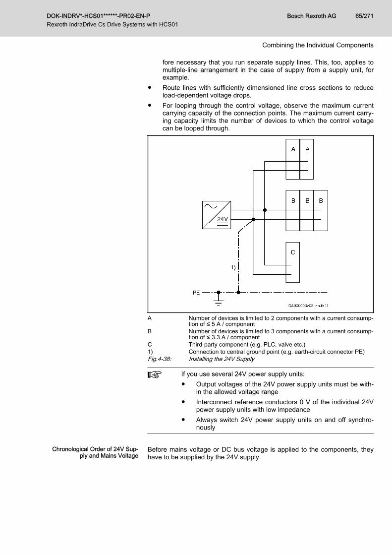
fore necessary that you run separate supply lines. This, too, applies tomultiple-line arrangement in the case of supply from a supply unit, forexample.
● Route lines with sufficiently dimensioned line cross sections to reduceload-dependent voltage drops.
● For looping through the control voltage, observe the maximum currentcarrying capacity of the connection points. The maximum current carry‐ing capacity limits the number of devices to which the control voltagecan be looped through.
A Number of devices is limited to 2 components with a current consump‐tion of ≤ 5 A / component
B Number of devices is limited to 3 components with a current consump‐tion of ≤ 3.3 A / component
C Third-party component (e.g. PLC, valve etc.)1) Connection to central ground point (e.g. earth-circuit connector PE)Fig.4-38: Installing the 24V Supply
If you use several 24V power supply units:● Output voltages of the 24V power supply units must be with‐
in the allowed voltage range● Interconnect reference conductors 0 V of the individual 24V
power supply units with low impedance● Always switch 24V power supply units on and off synchro‐
nously
Chronological Order of 24V Sup‐
ply and Mains VoltageBefore mains voltage or DC bus voltage is applied to the components, theyhave to be supplied by the 24V supply.
DOK-INDRV*-HCS01******-PR02-EN-P Rexroth IndraDrive Cs Drive Systems with HCS01
Bosch Rexroth AG 65/271
Combining the Individual Components
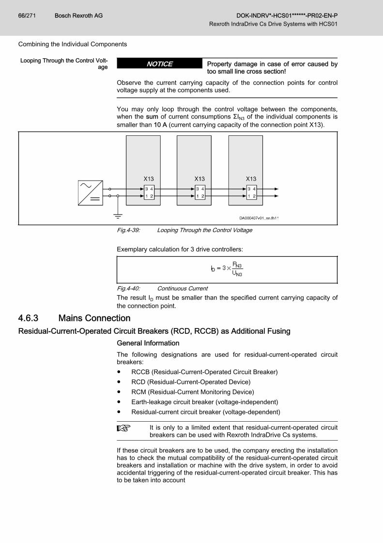
Looping Through the Control Volt‐age Property damage in case of error caused by
too small line cross section!NOTICE
Observe the current carrying capacity of the connection points for controlvoltage supply at the components used.
You may only loop through the control voltage between the components,when the sum of current consumptions ΣIN3 of the individual components issmaller than 10 A (current carrying capacity of the connection point X13).
Fig.4-39: Looping Through the Control Voltage Exemplary calculation for 3 drive controllers:
Fig.4-40: Continuous CurrentThe result ID must be smaller than the specified current carrying capacity ofthe connection point.
4.6.3 Mains Connection Residual-Current-Operated Circuit Breakers (RCD, RCCB) as Additional Fusing
General InformationThe following designations are used for residual-current-operated circuitbreakers:● RCCB (Residual-Current-Operated Circuit Breaker)● RCD (Residual-Current-Operated Device)● RCM (Residual-Current Monitoring Device)● Earth-leakage circuit breaker (voltage-independent)● Residual-current circuit breaker (voltage-dependent)
It is only to a limited extent that residual-current-operated circuitbreakers can be used with Rexroth IndraDrive Cs systems.
If these circuit breakers are to be used, the company erecting the installationhas to check the mutual compatibility of the residual-current-operated circuitbreakers and installation or machine with the drive system, in order to avoidaccidental triggering of the residual-current-operated circuit breaker. This hasto be taken into account
Bosch Rexroth AG DOK-INDRV*-HCS01******-PR02-EN-P Rexroth IndraDrive Cs Drive Systems with HCS01
66/271
Combining the Individual Components
● for switch-on processes, due to high asymmetric inrush currents and● during operation of the installation, due to leakage currents produced in
normal operation.
Cause of Leakage CurrentsFor the purpose of stepless speed variation with a high degree of positioningaccuracy and dynamic response, certain modulation procedures are neces‐sary for drive systems. For physical reasons, these modulation proceduresgive rise to inevitable leakage current produced during normal operation. Es‐pecially with unbalanced loads of the mains phases or a large number ofdrives it can easily reach some amperes (rms value).The leakage current is not sinusoidal but pulse-shaped. For this reason,measuring instruments normally sized for alternating currents in the range of50 Hz are not suited. Use measuring instruments with rms value measuringranges up to at least 150 kHz.The degree of leakage current depends on the following features of the in‐stallation:● Kind of inrush current limitation● Number, kind and size drives used● Length and cross section of connected motor power cables● Grounding conditions of the mains at the site of installation● Unbalance of the three-phase system● Kind of filters and chokes connected in the incoming circuit● EMC measures that are takenIf measures are taken to improve the electromagnetic compatibility (EMC) ofthe installation (mains filters, shielded lines), the leakage current in theground wire is inevitably increased, especially when switching on or in thecase of mains unbalance. Given these operating conditions, residual-current-operated circuit breakers can trigger without an error having occurred.The EMC measures are mainly based on capacitive short-circuiting of the in‐terference currents within the drive system. Inductive filter measures can re‐duce the leakage currents, but affect the dynamic response of the drive andbring about● higher construction volume● higher weight● expensive core material
Possibilities of UseMotor Cable Length Keep the motor cables as short as possible. Only short motor cables do allow
low leakage currents and thereby enable residual-current-operated circuitbreakers to work.
Kinds of Residual-Current-Operat‐ed Circuit Breakers
There are two kinds of residual-current-operated circuit breakers:1. Residual-current-operated circuit breakers sensitive to power pulse cur‐
rent (type A acc. to IEC 60755)These are normally used. However, it is only pulsating direct fault cur‐rents of a maximum of 5 mA and sinusoidal alternating fault currentsthat they switch off safely. This is why they are not allowed for devicesthat can generate smoothed direct fault currents. In the case of smooth‐ed direct fault currents that can be produced in power supply units,mains rectifiers and drive controllers with power converters in B6 circuit,
DOK-INDRV*-HCS01******-PR02-EN-P Rexroth IndraDrive Cs Drive Systems with HCS01
Bosch Rexroth AG 67/271
Combining the Individual Components
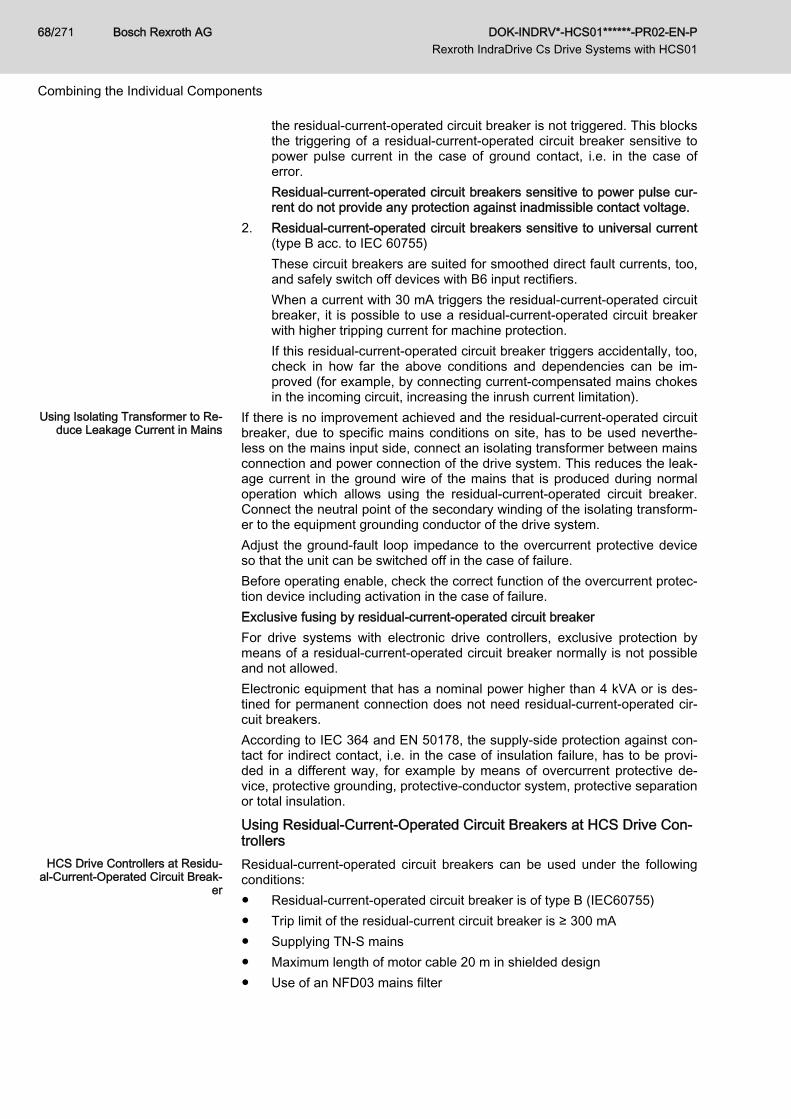
the residual-current-operated circuit breaker is not triggered. This blocksthe triggering of a residual-current-operated circuit breaker sensitive topower pulse current in the case of ground contact, i.e. in the case oferror.Residual-current-operated circuit breakers sensitive to power pulse cur‐rent do not provide any protection against inadmissible contact voltage.
2. Residual-current-operated circuit breakers sensitive to universal current(type B acc. to IEC 60755)These circuit breakers are suited for smoothed direct fault currents, too,and safely switch off devices with B6 input rectifiers.When a current with 30 mA triggers the residual-current-operated circuitbreaker, it is possible to use a residual-current-operated circuit breakerwith higher tripping current for machine protection.If this residual-current-operated circuit breaker triggers accidentally, too,check in how far the above conditions and dependencies can be im‐proved (for example, by connecting current-compensated mains chokesin the incoming circuit, increasing the inrush current limitation).
Using Isolating Transformer to Re‐duce Leakage Current in Mains
If there is no improvement achieved and the residual-current-operated circuitbreaker, due to specific mains conditions on site, has to be used neverthe‐less on the mains input side, connect an isolating transformer between mainsconnection and power connection of the drive system. This reduces the leak‐age current in the ground wire of the mains that is produced during normaloperation which allows using the residual-current-operated circuit breaker.Connect the neutral point of the secondary winding of the isolating transform‐er to the equipment grounding conductor of the drive system.Adjust the ground-fault loop impedance to the overcurrent protective deviceso that the unit can be switched off in the case of failure.Before operating enable, check the correct function of the overcurrent protec‐tion device including activation in the case of failure.Exclusive fusing by residual-current-operated circuit breakerFor drive systems with electronic drive controllers, exclusive protection bymeans of a residual-current-operated circuit breaker normally is not possibleand not allowed.Electronic equipment that has a nominal power higher than 4 kVA or is des‐tined for permanent connection does not need residual-current-operated cir‐cuit breakers.According to IEC 364 and EN 50178, the supply-side protection against con‐tact for indirect contact, i.e. in the case of insulation failure, has to be provi‐ded in a different way, for example by means of overcurrent protective de‐vice, protective grounding, protective-conductor system, protective separationor total insulation.
Using Residual-Current-Operated Circuit Breakers at HCS Drive Con‐trollers
HCS Drive Controllers at Residu‐al-Current-Operated Circuit Break‐
er
Residual-current-operated circuit breakers can be used under the followingconditions:● Residual-current-operated circuit breaker is of type B (IEC60755)● Trip limit of the residual-current circuit breaker is ≥ 300 mA● Supplying TN-S mains● Maximum length of motor cable 20 m in shielded design● Use of an NFD03 mains filter
Bosch Rexroth AG DOK-INDRV*-HCS01******-PR02-EN-P Rexroth IndraDrive Cs Drive Systems with HCS01
68/271
Combining the Individual Components
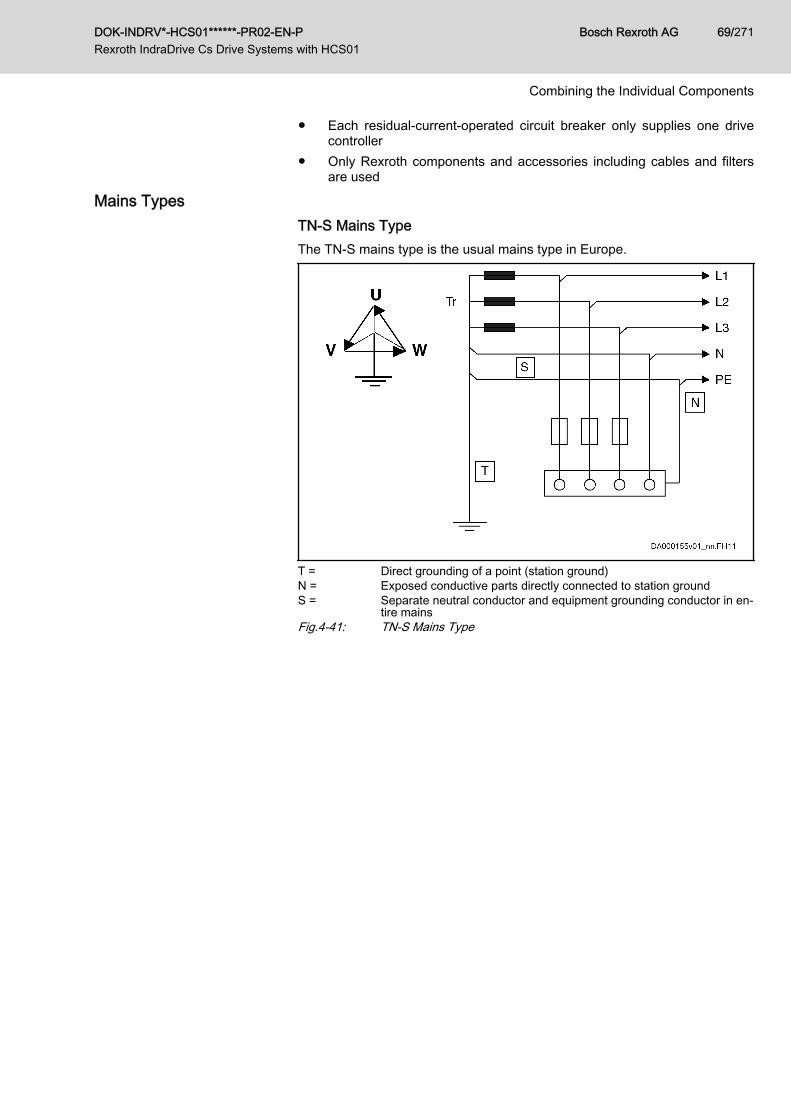
● Each residual-current-operated circuit breaker only supplies one drivecontroller
● Only Rexroth components and accessories including cables and filtersare used
Mains TypesTN-S Mains TypeThe TN-S mains type is the usual mains type in Europe.
T = Direct grounding of a point (station ground)N = Exposed conductive parts directly connected to station groundS = Separate neutral conductor and equipment grounding conductor in en‐
tire mainsFig.4-41: TN-S Mains Type
DOK-INDRV*-HCS01******-PR02-EN-P Rexroth IndraDrive Cs Drive Systems with HCS01
Bosch Rexroth AG 69/271
Combining the Individual Components
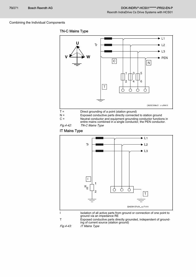
TN-C Mains Type
T = Direct grounding of a point (station ground)N = Exposed conductive parts directly connected to station groundC = Neutral conductor and equipment grounding conductor functions in
entire mains combined in a single conductor, the PEN conductor.Fig.4-42: TN-C Mains Type
IT Mains Type
I Isolation of all active parts from ground or connection of one point toground via an impedance RE
T Exposed conductive parts directly grounded, independent of ground‐ing of current source (station ground)
Fig.4-43: IT Mains Type
Bosch Rexroth AG DOK-INDRV*-HCS01******-PR02-EN-P Rexroth IndraDrive Cs Drive Systems with HCS01
70/271
Combining the Individual Components
Notes on Project Planning Damage to the devices by voltage arcing!For applications with in which static charging can occur (e.g. print‐ing, packaging), an isolating transformer with Ux ≤ 2.5% must beinstalled for operation at an IT mains.
Voltage increase in the case of ground fault!In case of the error "ground fault" in the IT mains type, higher vol‐tages against ground (device housing) than in error-free operationaffect the device.For operation at the IT mains type, the drive system includingmains filter and mains choke should be galvanically decoupledfrom the mains via an isolating transformer.In this way, the ground fault detection or monitoring can remaineffective in the installation.
When operating drive systems with HCS converters in other applicationswithout isolating transformer at the IT mains type:● Observe the allowed mains voltage ULN at the IT mains type of the cor‐
responding devices● Observe the allowed switching frequency fs; see note below● Check whether the ground fault detection of the mains does not trigger
accidentally● Check whether the interference suppression (that is only activated via
the parasitic mains capacitances of the ungrounded mains) is still suffi‐cient to comply with the required limit valuesThe EMC requirements are only complied with by further measures(special mains filters, among other things)!
TT System
T1 = Direct grounding of a point (station ground)T2 = Exposed conductive parts directly grounded, independent of ground‐
ing of current source (station ground)Fig.4-44: TT Mains System
DOK-INDRV*-HCS01******-PR02-EN-P Rexroth IndraDrive Cs Drive Systems with HCS01
Bosch Rexroth AG 71/271
Combining the Individual Components
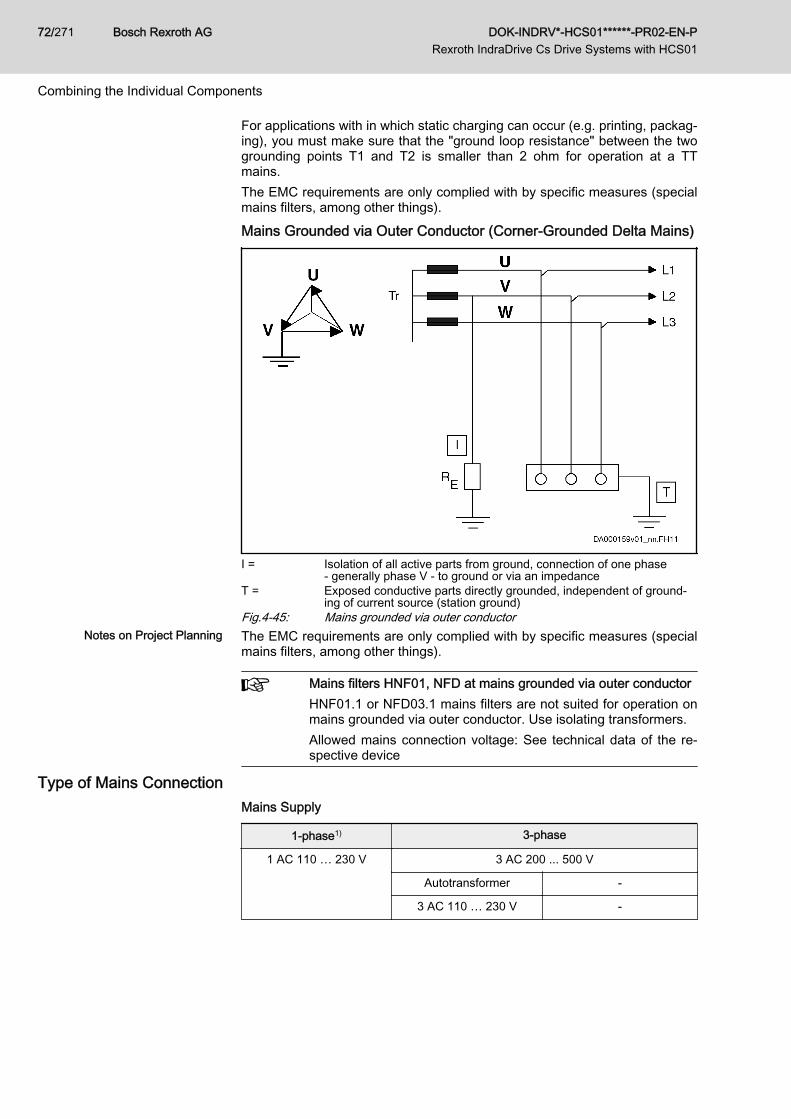
For applications with in which static charging can occur (e.g. printing, packag‐ing), you must make sure that the "ground loop resistance" between the twogrounding points T1 and T2 is smaller than 2 ohm for operation at a TTmains.The EMC requirements are only complied with by specific measures (specialmains filters, among other things).
Mains Grounded via Outer Conductor (Corner-Grounded Delta Mains)
I = Isolation of all active parts from ground, connection of one phase‑ generally phase V - to ground or via an impedance
T = Exposed conductive parts directly grounded, independent of ground‐ing of current source (station ground)
Fig.4-45: Mains grounded via outer conductorNotes on Project Planning The EMC requirements are only complied with by specific measures (special
mains filters, among other things).
Mains filters HNF01, NFD at mains grounded via outer conductorHNF01.1 or NFD03.1 mains filters are not suited for operation onmains grounded via outer conductor. Use isolating transformers.Allowed mains connection voltage: See technical data of the re‐spective device
Type of Mains ConnectionMains Supply
1-phase1) 3-phase
1 AC 110 … 230 V 3 AC 200 ... 500 V
Autotransformer -
3 AC 110 … 230 V -
Bosch Rexroth AG DOK-INDRV*-HCS01******-PR02-EN-P Rexroth IndraDrive Cs Drive Systems with HCS01
72/271
Combining the Individual Components
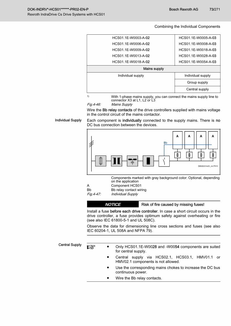
HCS01.1E-W0003-A-02HCS01.1E-W0006-A-02HCS01.1E-W0009-A-02HCS01.1E-W0013-A-02HCS01.1E-W0018-A-02
HCS01.1E-W0005-A-03HCS01.1E-W0008-A-03HCS01.1E-W0018-A-03HCS01.1E-W0028-A-03HCS01.1E-W0054-A-03
Mains supply
Individual supply Individual supply
Group supply
Central supply
1) With 1-phase mains supply, you can connect the mains supply line toconnector X3 at L1, L2 or L3
Fig.4-46: Mains SupplyWire the Bb relay contacts of the drive controllers supplied with mains voltagein the control circuit of the mains contactor.
Individual Supply Each component is individually connected to the supply mains. There is noDC bus connection between the devices.
Components marked with gray background color: Optional, dependingon the application
A Component HCS01Bb Bb relay contact wiringFig.4-47: Individual Supply
Risk of fire caused by missing fuses!NOTICEInstall a fuse before each drive controller. In case a short circuit occurs in thedrive controller, a fuse provides optimum safety against overheating or fire(see also IEC 61800‑5‑1 and UL 508C).Observe the data for dimensioning line cross sections and fuses (see alsoIEC 60204‑1, UL 508A and NFPA 79).
Central Supply ● Only HCS01.1E‑W0028 and ‑W0054 components are suited
for central supply.● Central supply via HCS02.1, HCS03.1, HMV01.1 or
HMV02.1 components is not allowed.● Use the corresponding mains chokes to increase the DC bus
continuous power.● Wire the Bb relay contacts.
DOK-INDRV*-HCS01******-PR02-EN-P Rexroth IndraDrive Cs Drive Systems with HCS01
Bosch Rexroth AG 73/271
Combining the Individual Components
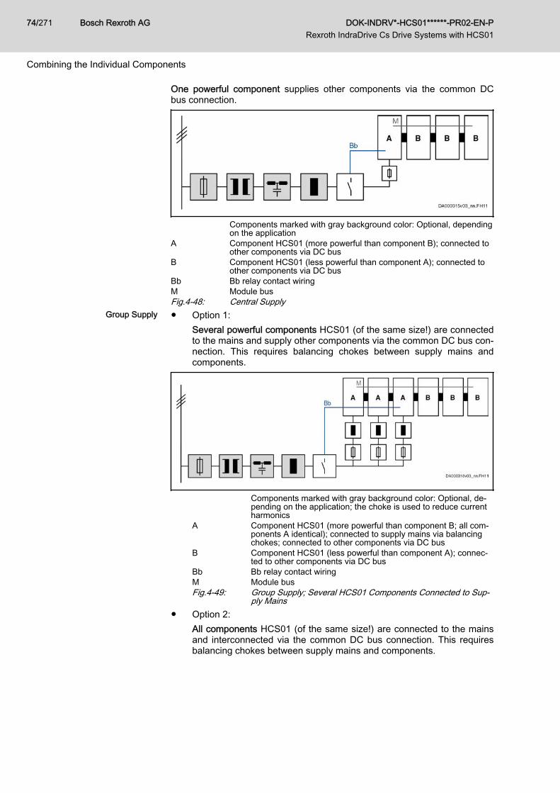
One powerful component supplies other components via the common DCbus connection.
Components marked with gray background color: Optional, dependingon the application
A Component HCS01 (more powerful than component B); connected toother components via DC bus
B Component HCS01 (less powerful than component A); connected toother components via DC bus
Bb Bb relay contact wiringM Module busFig.4-48: Central Supply
Group Supply ● Option 1:Several powerful components HCS01 (of the same size!) are connectedto the mains and supply other components via the common DC bus con‐nection. This requires balancing chokes between supply mains andcomponents.
Components marked with gray background color: Optional, de‐pending on the application; the choke is used to reduce currentharmonics
A Component HCS01 (more powerful than component B; all com‐ponents A identical); connected to supply mains via balancingchokes; connected to other components via DC bus
B Component HCS01 (less powerful than component A); connec‐ted to other components via DC bus
Bb Bb relay contact wiringM Module busFig.4-49: Group Supply; Several HCS01 Components Connected to Sup‐
ply Mains● Option 2:
All components HCS01 (of the same size!) are connected to the mainsand interconnected via the common DC bus connection. This requiresbalancing chokes between supply mains and components.
Bosch Rexroth AG DOK-INDRV*-HCS01******-PR02-EN-P Rexroth IndraDrive Cs Drive Systems with HCS01
74/271
Combining the Individual Components
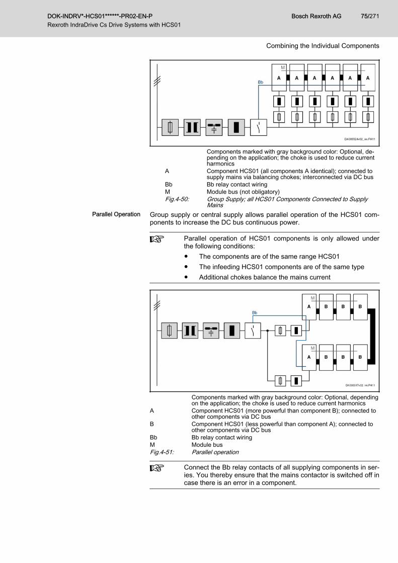
Components marked with gray background color: Optional, de‐pending on the application; the choke is used to reduce currentharmonics
A Component HCS01 (all components A identical); connected tosupply mains via balancing chokes; interconnected via DC bus
Bb Bb relay contact wiringM Module bus (not obligatory)Fig.4-50: Group Supply; all HCS01 Components Connected to Supply
MainsParallel Operation Group supply or central supply allows parallel operation of the HCS01 com‐
ponents to increase the DC bus continuous power.
Parallel operation of HCS01 components is only allowed underthe following conditions:● The components are of the same range HCS01● The infeeding HCS01 components are of the same type● Additional chokes balance the mains current
Components marked with gray background color: Optional, dependingon the application; the choke is used to reduce current harmonics
A Component HCS01 (more powerful than component B); connected toother components via DC bus
B Component HCS01 (less powerful than component A); connected toother components via DC bus
Bb Bb relay contact wiringM Module busFig.4-51: Parallel operation
Connect the Bb relay contacts of all supplying components in ser‐ies. You thereby ensure that the mains contactor is switched off incase there is an error in a component.
DOK-INDRV*-HCS01******-PR02-EN-P Rexroth IndraDrive Cs Drive Systems with HCS01
Bosch Rexroth AG 75/271
Combining the Individual Components

Mains Connected Load and Mains Current Technical Data of the ComponentsSee index entry● HCS01 → Mains voltage, data● HCS01 → DC bus, data
Calculating the Mains-Side Phase Current The mains-side phase current is required for the following cases:● Selecting mains contactor● Determining fuses in the mains connection● Determining line cross section● Selecting other components in the mains connection (mains filter, mains
choke)Operation Under Rated Conditions For data on mains contactor, fuses and cross section in operation under rat‐
ed conditions, see technical data of the respective device.Operation at Partial Load Operation at partial load can lead to smaller mains contactors, fuses and line
cross sections.If defined data for operation at partial load are available, the mains-sidephase current can be determined as follows:1. Determine motor power
Take power of drive controller-motor combination from Rexroth Indra‐Size or calculate it.
PmHa Mechanical nominal power for main drives (shaftoutput) [kW]
Mn Nominal motor torque [Nm]nn Nominal motor speed [min-1]
2. Determine DC bus power from motor power and efficiency
PDC Required DC bus continuous power [W]Meff Effective torque in Nmnm Average speed in min-1
k Factor for motor and controller efficiency = 1.253. Add powers of all axes at common DC bus and put them into relation to
rated power of supply unit⇒ Partial load of PDC_cont is available
4. Determine power factor TPF for partial load (TPF = Total Power Factor)For the value TPF at rated power and TPF10 (at 10% of rated power),see technical data (mains voltage) of the component.
Bosch Rexroth AG DOK-INDRV*-HCS01******-PR02-EN-P Rexroth IndraDrive Cs Drive Systems with HCS01
76/271
Combining the Individual Components
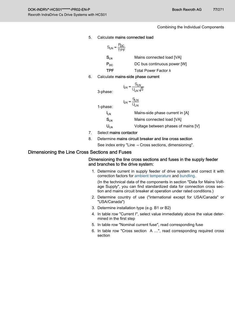
5. Calculate mains connected load
SLN Mains connected load [VA]PDC DC bus continuous power [W]TPF Total Power Factor λ
6. Calculate mains-side phase current
3-phase:
1-phase: ILN Mains-side phase current in [A]SLN Mains connected load [VA]ULN Voltage between phases of mains [V]
7. Select mains contactor8. Determine mains circuit breaker and line cross section
See index entry "Line → Cross sections, dimensioning".
Dimensioning the Line Cross Sections and Fuses Dimensioning the line cross sections and fuses in the supply feederand branches to the drive system:
1. Determine current in supply feeder of drive system and correct it withcorrection factors for ambient temperature and bundling.(In the technical data of the components in section "Data for Mains Volt‐age Supply", you can find standardized data for connection cross sec‐tion and mains circuit breaker at operation under rated conditions.)
2. Determine country of use ("international except for USA/Canada" or"USA/Canada")
3. Determine installation type (e.g. B1 or B2)4. In table row "Current I", select value immediately above the value deter‐
mined in the first step5. In table row "Nominal current fuse", read corresponding fuse6. In table row "Cross section A …", read corresponding required cross
section
DOK-INDRV*-HCS01******-PR02-EN-P Rexroth IndraDrive Cs Drive Systems with HCS01
Bosch Rexroth AG 77/271
Combining the Individual Components
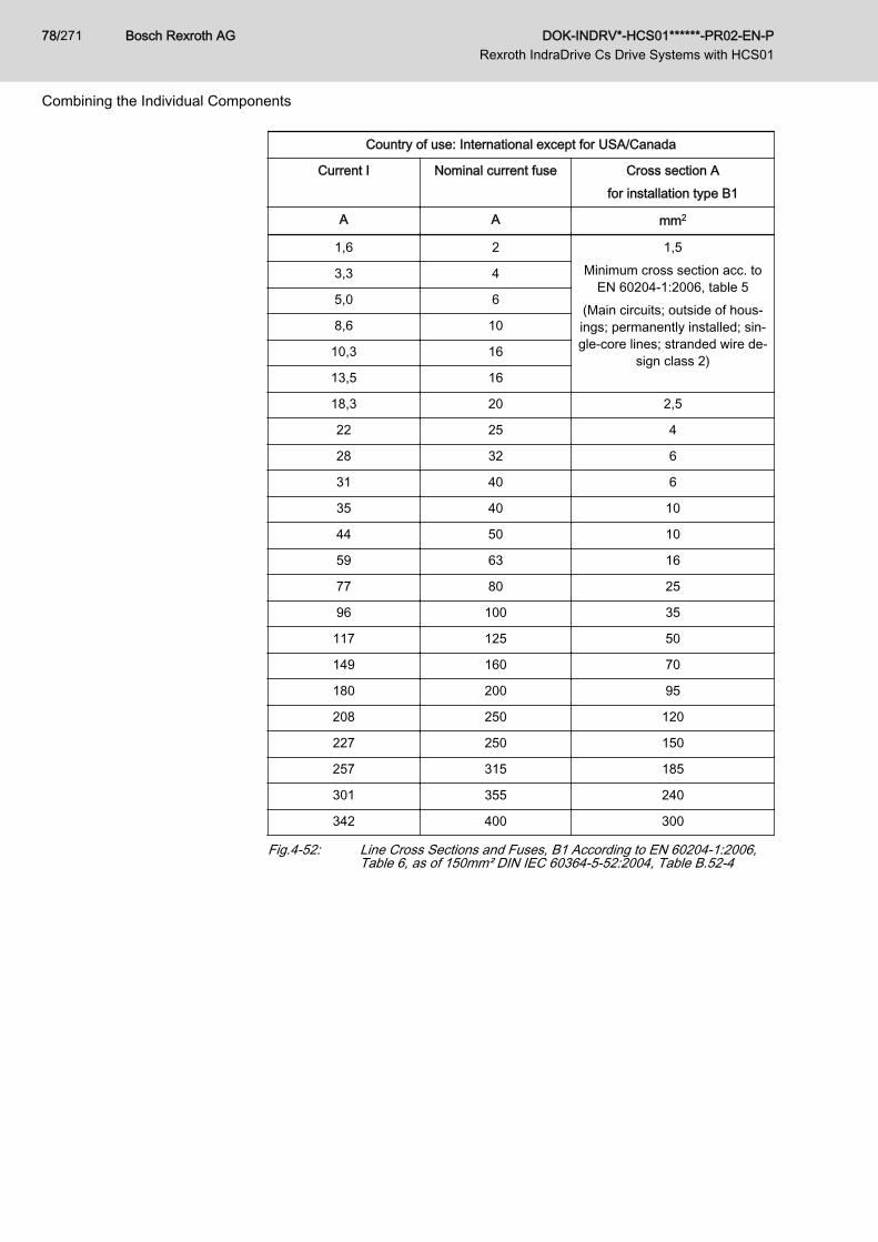
Country of use: International except for USA/Canada
Current I Nominal current fuse Cross section Afor installation type B1
A A mm2
1,6 2 1,5Minimum cross section acc. to
EN 60204‑1:2006, table 5(Main circuits; outside of hous‐ings; permanently installed; sin‐gle-core lines; stranded wire de‐
sign class 2)
3,3 4
5,0 6
8,6 10
10,3 16
13,5 16
18,3 20 2,5
22 25 4
28 32 6
31 40 6
35 40 10
44 50 10
59 63 16
77 80 25
96 100 35
117 125 50
149 160 70
180 200 95
208 250 120
227 250 150
257 315 185
301 355 240
342 400 300
Fig.4-52: Line Cross Sections and Fuses, B1 According to EN 60204-1:2006,Table 6, as of 150mm² DIN IEC 60364-5-52:2004, Table B.52-4
Bosch Rexroth AG DOK-INDRV*-HCS01******-PR02-EN-P Rexroth IndraDrive Cs Drive Systems with HCS01
78/271
Combining the Individual Components

Country of use: International except for USA/Canada
Current I Nominal current fuse Cross section Afor installation type B2
A A mm2
1,6 2 0,75Minimum cross section acc. to
EN 60204‑1:2006, table 5(Main circuits; outside of hous‐
ings; permanently installed; mul‐ti-core lines)
3,3 4
5,0 6
8,5 10
10,1 16 1,0
13,1 16 1,5
17,4 20 2,5
23 25 4
28 32 6
30 40 6
35 40 10
40 50 10
54 63 16
70 80 25
86 100 35
103 125 50
130 160 70
156 200 95
179 200 120
195 224 150
221 250 185
258 315 240
294 355 300
Fig.4-53: Line Cross Sections and Fuses, B2 According to EN 60204-1:2006,Table 6, as of 150mm² DIN IEC 60364-5-52:2004, Table B.52-4
DOK-INDRV*-HCS01******-PR02-EN-P Rexroth IndraDrive Cs Drive Systems with HCS01
Bosch Rexroth AG 79/271
Combining the Individual Components
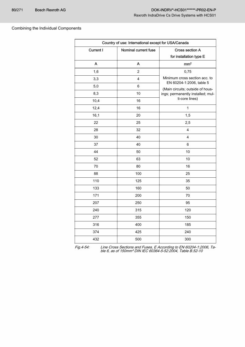
Country of use: International except for USA/Canada
Current I Nominal current fuse Cross section Afor installation type E
A A mm2
1,6 2 0,75Minimum cross section acc. to
EN 60204‑1:2006, table 5(Main circuits; outside of hous‐
ings; permanently installed; mul‐ti-core lines)
3,3 4
5,0 6
8,3 10
10,4 16
12,4 16 1
16,1 20 1,5
22 25 2,5
28 32 4
30 40 4
37 40 6
44 50 10
52 63 10
70 80 16
88 100 25
110 125 35
133 160 50
171 200 70
207 250 95
240 315 120
277 355 150
316 400 185
374 425 240
432 500 300
Fig.4-54: Line Cross Sections and Fuses, E According to EN 60204-1:2006, Ta‐ble 6, as of 150mm² DIN IEC 60364-5-52:2004, Table B.52-10
Bosch Rexroth AG DOK-INDRV*-HCS01******-PR02-EN-P Rexroth IndraDrive Cs Drive Systems with HCS01
80/271
Combining the Individual Components
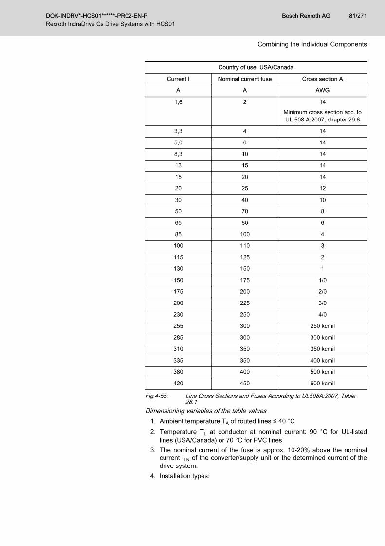
Country of use: USA/Canada
Current I Nominal current fuse Cross section A
A A AWG
1,6 2 14Minimum cross section acc. toUL 508 A:2007, chapter 29.6
3,3 4 14
5,0 6 14
8,3 10 14
13 15 14
15 20 14
20 25 12
30 40 10
50 70 8
65 80 6
85 100 4
100 110 3
115 125 2
130 150 1
150 175 1/0
175 200 2/0
200 225 3/0
230 250 4/0
255 300 250 kcmil
285 300 300 kcmil
310 350 350 kcmil
335 350 400 kcmil
380 400 500 kcmil
420 450 600 kcmil
Fig.4-55: Line Cross Sections and Fuses According to UL508A:2007, Table28.1
Dimensioning variables of the table values1. Ambient temperature TA of routed lines ≤ 40 °C2. Temperature TL at conductor at nominal current: 90 °C for UL-listed
lines (USA/Canada) or 70 °C for PVC lines3. The nominal current of the fuse is approx. 10-20% above the nominal
current ILN of the converter/supply unit or the determined current of thedrive system.
4. Installation types:
DOK-INDRV*-HCS01******-PR02-EN-P Rexroth IndraDrive Cs Drive Systems with HCS01
Bosch Rexroth AG 81/271
Combining the Individual Components
● B1 according to IEC 60364-5-52, e.g. stranded wires routed in ca‐ble duct
● B2 according to IEC 60364-5-52, e.g. multi-core line routed in ca‐ble duct
● E according to EN 60204-1, e.g. multi-core line routed on open ca‐ble tray
● According to NFPA 79 (external wiring), UL508A (internal wiring),NEC, NFPA 70:– 1 cable with 3 conductors, 1 neutral conductor and 1 equip‐
ment grounding conductor– Routed in pipe on the wallInternal wiring: Routing inside of control cabinet or inside of devi‐cesExternal wiring: Routing outside of control cabinetField wiring: Data of cross sections of terminal connectors wired bythe user (in the field)
5. Recommendation for design of the fuses: ● International except for USA/Canada: Class gG; 500V, 690V; de‐
sign NH, D (DIAZED) or D0 (NEOZED)
CharacteristicIn the case of error (e.g. ground fault at connections L+, L-), fusesof characteristic gG (general-purpose fuse link for general instal‐lations), as well as circuit breakers, protect the lines in the supplyfeeder to the drive system.To protect the semiconductors in the input of supply units andconverters, you can use fuses of characteristic gR.
● USA / Canada: Class J; 600V
Circuit breakerAs an alternative to fuses, you can use circuit breakers with lowerpeak let-through current and lower let-through energy than thecorresponding fuse.
Correction factorsFor deviating dimensioning variables, the corresponding stand‐ards specify correction factors.Below you can find the correction factors for ambient temperatureand numbers of routed lines and circuits. If necessary, multiplythe determined current in the supply feeder with these factors.
Bosch Rexroth AG DOK-INDRV*-HCS01******-PR02-EN-P Rexroth IndraDrive Cs Drive Systems with HCS01
82/271
Combining the Individual Components
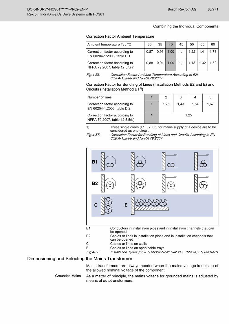
Correction Factor Ambient Temperature
Ambient temperature TA / °C 30 35 40 45 50 55 60
Correction factor according toEN 60204‑1:2006, table D.1
0,87 0,93 1,00 1,1 1,22 1,41 1,73
Correction factor according toNFPA 79:2007, table 12.5.5(a)
0,88 0,94 1,00 1,1 1.18 1.32 1,52
Fig.4-56: Correction Factor Ambient Temperature According to EN60204-1:2006 and NFPA 79:2007
Correction Factor for Bundling of Lines (Installation Methods B2 and E) andCircuits (Installation Method B11))
Number of lines 1 2 3 4 5
Correction factor according toEN 60204‑1:2006, table D.2
1 1,25 1,43 1,54 1,67
Correction factor according toNFPA 79:2007, table 12.5.5(b)
1 1,25
1) Three single cores (L1, L2, L3) for mains supply of a device are to beconsidered as one circuit.
Fig.4-57: Correction Factor for Bundling of Lines and Circuits According to EN60204-1:2006 and NFPA 79:2007
B1 Conductors in installation pipes and in installation channels that canbe opened
B2 Cables or lines in installation pipes and in installation channels thatcan be opened
C Cables or lines on wallsE Cables or lines on open cable traysFig.4-58: Installation Types (cf. IEC 60364-5-52; DIN VDE 0298-4; EN 60204-1)
Dimensioning and Selecting the Mains TransformerMains transformers are always needed when the mains voltage is outside ofthe allowed nominal voltage of the component.
Grounded Mains As a matter of principle, the mains voltage for grounded mains is adjusted bymeans of autotransformers.
DOK-INDRV*-HCS01******-PR02-EN-P Rexroth IndraDrive Cs Drive Systems with HCS01
Bosch Rexroth AG 83/271
Combining the Individual Components

Ungrounded Mains As a matter of principle, the mains voltage for ungrounded mains is adjustedby means of isolating transformers to avoid prevent overvoltages betweenouter conductor and ground. Short-circuit voltage of the isolating transformer:≤ 4%
Applications for Autotransformers With HCS01 components, there are two applications for which autotransform‐ers are necessary:1. HCS01.1E-W00xx-A-02 components are used:
With a mains voltage of 3 AC 400 V, the voltage must be adjusted viaan autotransformer to use HCS01.1E-W00xx-A-02 components with aninput voltage range of 3 AC 110…230 V.
2. An MSM motor is used in conjunction with an HCS01.1E-W00xx-A-03component:MSM motors have been dimensioned for a voltage of 230 V. To operateMSM motors at a mains voltage of 3 AC 400 V at an HCS01.1E-W00xx-A-03 component, the mains voltage must be adjusted to 3 AC 230 V viaan autotransformer.
Dimensioning the Mains FilterCriteria for Selecting the Mains Fil‐
terTake the following criteria into account for selecting the appropriate mains fil‐ter:● EMC limit value class on site● Ambient conditions on site● Harmonics on mains voltage on site● Loading by mains voltage and mains frequency on site● Loading by harmonics on site● Loading by mains-side phase current● Total length of connected power cables● Sum of leakage capacitances● Clock frequency of drive controller
How to Proceed for Selecting theMains Filter
The selection of the mains filter is significantly determined by the operatingconditions.How to proceed for selecting the mains filter:1. Determine the required EMC limit value class for the application.2. Determine the maximum applied mains voltage.
Observe that not all Rexroth IndraDrive Cs mains filters are suited for amains voltage of 3 AC 500 V.Check whether the mains voltage of the mains filter is loaded with har‐monics and still allowed for the mains filter.If necessary, reduce the harmonics on site.
3. Determine the kind of mains connection, such as central supply, groupsupply etc. (to do this, it is useful to outline the involved componentsand their interaction).
4. Calculate the mains-side phase current of the mains filter. You can findthe procedure for calculating the mains-side phase current in a separatechapter (see index entry "Phase current → Calculating"). For selectingthe components, calculate the effective rms value.
Bosch Rexroth AG DOK-INDRV*-HCS01******-PR02-EN-P Rexroth IndraDrive Cs Drive Systems with HCS01
84/271
Combining the Individual Components

Check or determine the maximum occurring ambient temperature. Se‐lect a mains filter with higher nominal current, when the ambient temper‐ature is above 45 °C.
5. Select a mains contactor the nominal current of which does not exceednominal current of the mains filter.
6. Determine the number of drive axes.7. Determine the total length of the connected power cables.8. Determine the sum of the leakage capacitances on the load side of the
mains filter.The sum of the leakage capacitances results from the number of operat‐ed axes and the length of the connected power cables. You can find theprocedure for determining the leakage capacitance in a separate chap‐ter (see index entry "Leakage capacitance → Determining").
9. Take the clock frequency of the drive controller into account.The higher the clock frequency of the drive controller, the higher theleakage currents and the interference emissions they involve.The following leakage capacitances (motor cable + motor) mustn't beexceeded per drive controller.
HCS01.1E-W0003, -W0006, -W0009, -W0013
Clock frequency[kHz]
Maximum leakage capacitance(Motor + cable) per device [nF]
Motor cable length[m]
4 33 40
8 17 20
12 13 15
16 5 5
Fig.4-59: Clock Frequency, Leakage Capacitance, Motor Cable LengthHCS01.1E-W0005, -W0008
Clock frequency[kHz]
Maximum leakage capacitance(Motor + cable) per device [nF]
Motor cable length[m]
4 34 40
8 18 20
12 14 15
16 6 5
Fig.4-60: Clock Frequency, Leakage Capacitance, Motor Cable LengthHCS01.1E-W0018, -W0028
Clock frequency[kHz]
Maximum leakage capacitance(Motor + cable) per device [nF]
Motor cable length[m]
4 40 40
8 24 20
DOK-INDRV*-HCS01******-PR02-EN-P Rexroth IndraDrive Cs Drive Systems with HCS01
Bosch Rexroth AG 85/271
Combining the Individual Components
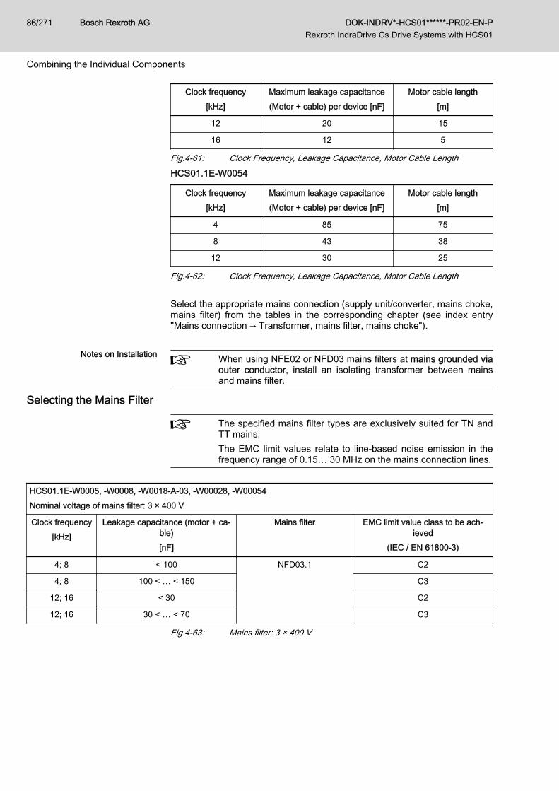
Clock frequency[kHz]
Maximum leakage capacitance(Motor + cable) per device [nF]
Motor cable length[m]
12 20 15
16 12 5
Fig.4-61: Clock Frequency, Leakage Capacitance, Motor Cable LengthHCS01.1E-W0054
Clock frequency[kHz]
Maximum leakage capacitance(Motor + cable) per device [nF]
Motor cable length[m]
4 85 75
8 43 38
12 30 25
Fig.4-62: Clock Frequency, Leakage Capacitance, Motor Cable Length Select the appropriate mains connection (supply unit/converter, mains choke,mains filter) from the tables in the corresponding chapter (see index entry"Mains connection → Transformer, mains filter, mains choke").
Notes on Installation When using NFE02 or NFD03 mains filters at mains grounded viaouter conductor, install an isolating transformer between mainsand mains filter.
Selecting the Mains Filter
The specified mains filter types are exclusively suited for TN andTT mains.The EMC limit values relate to line-based noise emission in thefrequency range of 0.15… 30 MHz on the mains connection lines.
HCS01.1E-W0005, -W0008, -W0018-A-03, -W00028, -W00054Nominal voltage of mains filter: 3 × 400 V
Clock frequency[kHz]
Leakage capacitance (motor + ca‐ble)[nF]
Mains filter EMC limit value class to be ach‐ieved
(IEC / EN 61800-3)
4; 8 < 100 NFD03.1 C2
4; 8 100 < … < 150 C3
12; 16 < 30 C2
12; 16 30 < … < 70 C3
Fig.4-63: Mains filter; 3 × 400 V
Bosch Rexroth AG DOK-INDRV*-HCS01******-PR02-EN-P Rexroth IndraDrive Cs Drive Systems with HCS01
86/271
Combining the Individual Components
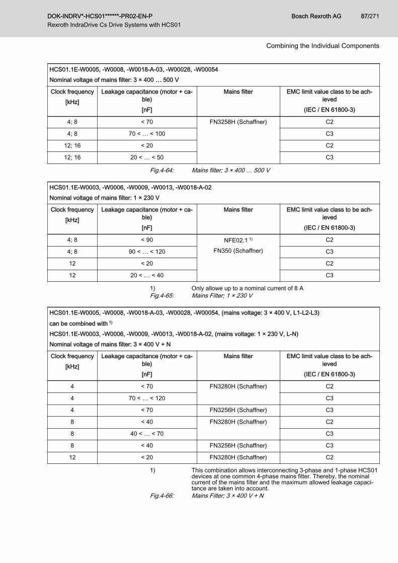
HCS01.1E-W0005, -W0008, -W0018-A-03, -W00028, -W00054Nominal voltage of mains filter: 3 × 400 … 500 V
Clock frequency[kHz]
Leakage capacitance (motor + ca‐ble)[nF]
Mains filter EMC limit value class to be ach‐ieved
(IEC / EN 61800-3)
4; 8 < 70 FN3258H (Schaffner) C2
4; 8 70 < … < 100 C3
12; 16 < 20 C2
12; 16 20 < … < 50 C3
Fig.4-64: Mains filter; 3 × 400 … 500 V
HCS01.1E-W0003, -W0006, -W0009, -W0013, -W0018-A-02Nominal voltage of mains filter: 1 × 230 V
Clock frequency[kHz]
Leakage capacitance (motor + ca‐ble)[nF]
Mains filter EMC limit value class to be ach‐ieved
(IEC / EN 61800-3)
4; 8 < 90 NFE02.1 1)
FN350 (Schaffner)
C2
4; 8 90 < … < 120 C3
12 < 20 C2
12 20 < … < 40 C3
1) Only allowe up to a nominal current of 8 AFig.4-65: Mains Filter; 1 × 230 V
HCS01.1E-W0005, -W0008, -W0018-A-03, -W00028, -W00054, (mains voltage: 3 × 400 V, L1-L2-L3)
can be combined with 1)
HCS01.1E-W0003, -W0006, -W0009, -W0013, -W0018-A-02, (mains voltage: 1 × 230 V, L-N)Nominal voltage of mains filter: 3 × 400 V + N
Clock frequency[kHz]
Leakage capacitance (motor + ca‐ble)[nF]
Mains filter EMC limit value class to be ach‐ieved
(IEC / EN 61800-3)
4 < 70 FN3280H (Schaffner) C2
4 70 < … < 120 C3
4 < 70 FN3256H (Schaffner) C3
8 < 40 FN3280H (Schaffner) C2
8 40 < … < 70 C3
8 < 40 FN3256H (Schaffner) C3
12 < 20 FN3280H (Schaffner) C2
1) This combination allows interconnecting 3‑phase and 1‑phase HCS01devices at one common 4‑phase mains filter. Thereby, the nominalcurrent of the mains filter and the maximum allowed leakage capaci‐tance are taken into account.
Fig.4-66: Mains Filter; 3 × 400 V + N
DOK-INDRV*-HCS01******-PR02-EN-P Rexroth IndraDrive Cs Drive Systems with HCS01
Bosch Rexroth AG 87/271
Combining the Individual Components
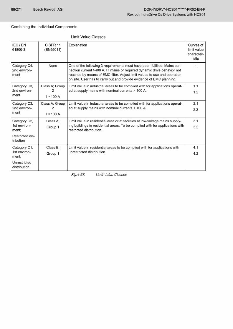
Limit Value Classes
IEC / EN61800-3
CISPR 11(EN55011)
Explanation Curves oflimit valuecharacter‐
istic
Category C4,2nd environ‐ment
None One of the following 3 requirements must have been fulfilled: Mains con‐nection current >400 A, IT mains or required dynamic drive behavior notreached by means of EMC filter. Adjust limit values to use and operationon site. User has to carry out and provide evidence of EMC planning.
-
Category C3,2nd environ‐ment
Class A; Group2
I > 100 A
Limit value in industrial areas to be complied with for applications operat‐ed at supply mains with nominal currents > 100 A.
1.11.2
Category C3,2nd environ‐ment
Class A; Group2
I < 100 A
Limit value in industrial areas to be complied with for applications operat‐ed at supply mains with nominal currents < 100 A.
2.12.2
Category C2,1st environ‐ment;Restricted dis‐tribution
Class A;Group 1
Limit value in residential area or at facilities at low-voltage mains supply‐ing buildings in residential areas. To be complied with for applications withrestricted distribution.
3.13.2
Category C1,1st environ‐ment;Unrestricteddistribution
Class B;Group 1
Limit value in residential areas to be complied with for applications withunrestricted distribution.
4.14.2
Fig.4-67: Limit Value Classes
Bosch Rexroth AG DOK-INDRV*-HCS01******-PR02-EN-P Rexroth IndraDrive Cs Drive Systems with HCS01
88/271
Combining the Individual Components
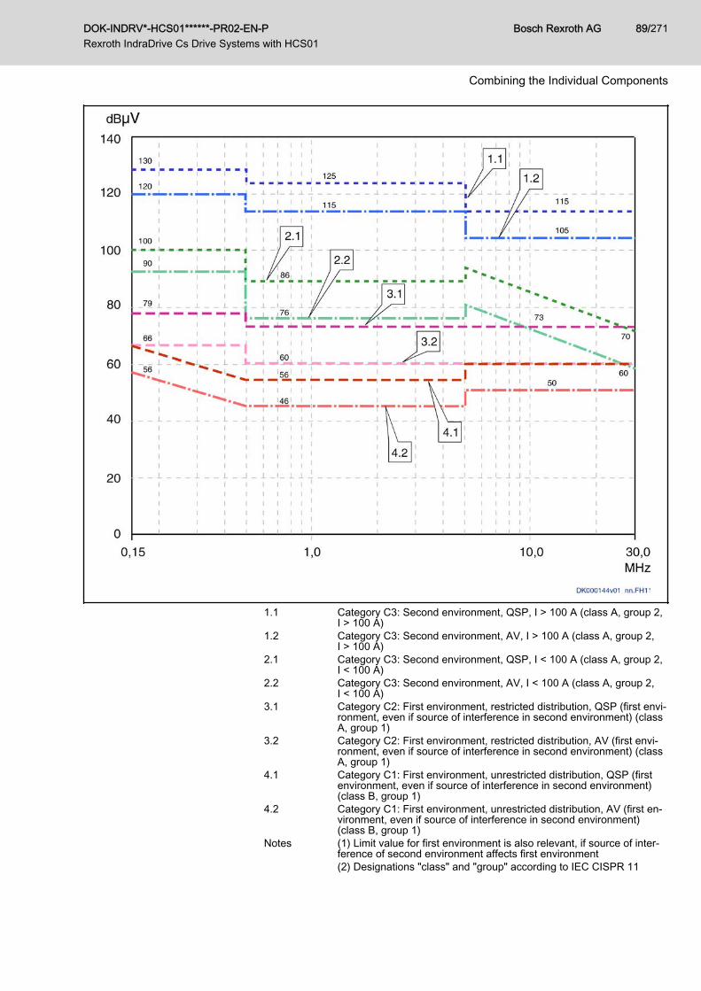
1.1 Category C3: Second environment, QSP, I > 100 A (class A, group 2,I > 100 A)
1.2 Category C3: Second environment, AV, I > 100 A (class A, group 2,I > 100 A)
2.1 Category C3: Second environment, QSP, I < 100 A (class A, group 2,I < 100 A)
2.2 Category C3: Second environment, AV, I < 100 A (class A, group 2,I < 100 A)
3.1 Category C2: First environment, restricted distribution, QSP (first envi‐ronment, even if source of interference in second environment) (classA, group 1)
3.2 Category C2: First environment, restricted distribution, AV (first envi‐ronment, even if source of interference in second environment) (classA, group 1)
4.1 Category C1: First environment, unrestricted distribution, QSP (firstenvironment, even if source of interference in second environment)(class B, group 1)
4.2 Category C1: First environment, unrestricted distribution, AV (first en‐vironment, even if source of interference in second environment)(class B, group 1)
Notes (1) Limit value for first environment is also relevant, if source of inter‐ference of second environment affects first environment(2) Designations "class" and "group" according to IEC CISPR 11
DOK-INDRV*-HCS01******-PR02-EN-P Rexroth IndraDrive Cs Drive Systems with HCS01
Bosch Rexroth AG 89/271
Combining the Individual Components
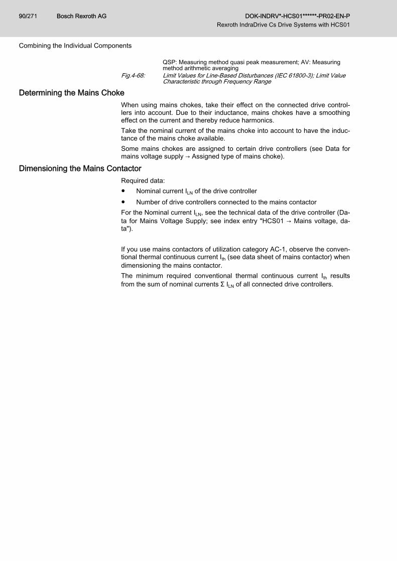
QSP: Measuring method quasi peak measurement; AV: Measuringmethod arithmetic averaging
Fig.4-68: Limit Values for Line-Based Disturbances (IEC 61800-3); Limit ValueCharacteristic through Frequency Range
Determining the Mains ChokeWhen using mains chokes, take their effect on the connected drive control‐lers into account. Due to their inductance, mains chokes have a smoothingeffect on the current and thereby reduce harmonics.Take the nominal current of the mains choke into account to have the induc‐tance of the mains choke available.Some mains chokes are assigned to certain drive controllers (see Data formains voltage supply → Assigned type of mains choke).
Dimensioning the Mains ContactorRequired data:● Nominal current ILN of the drive controller● Number of drive controllers connected to the mains contactorFor the Nominal current ILN, see the technical data of the drive controller (Da‐ta for Mains Voltage Supply; see index entry "HCS01 → Mains voltage, da‐ta"). If you use mains contactors of utilization category AC‑1, observe the conven‐tional thermal continuous current Ith (see data sheet of mains contactor) whendimensioning the mains contactor.The minimum required conventional thermal continuous current Ith resultsfrom the sum of nominal currents Σ ILN of all connected drive controllers.
Bosch Rexroth AG DOK-INDRV*-HCS01******-PR02-EN-P Rexroth IndraDrive Cs Drive Systems with HCS01
90/271
Combining the Individual Components
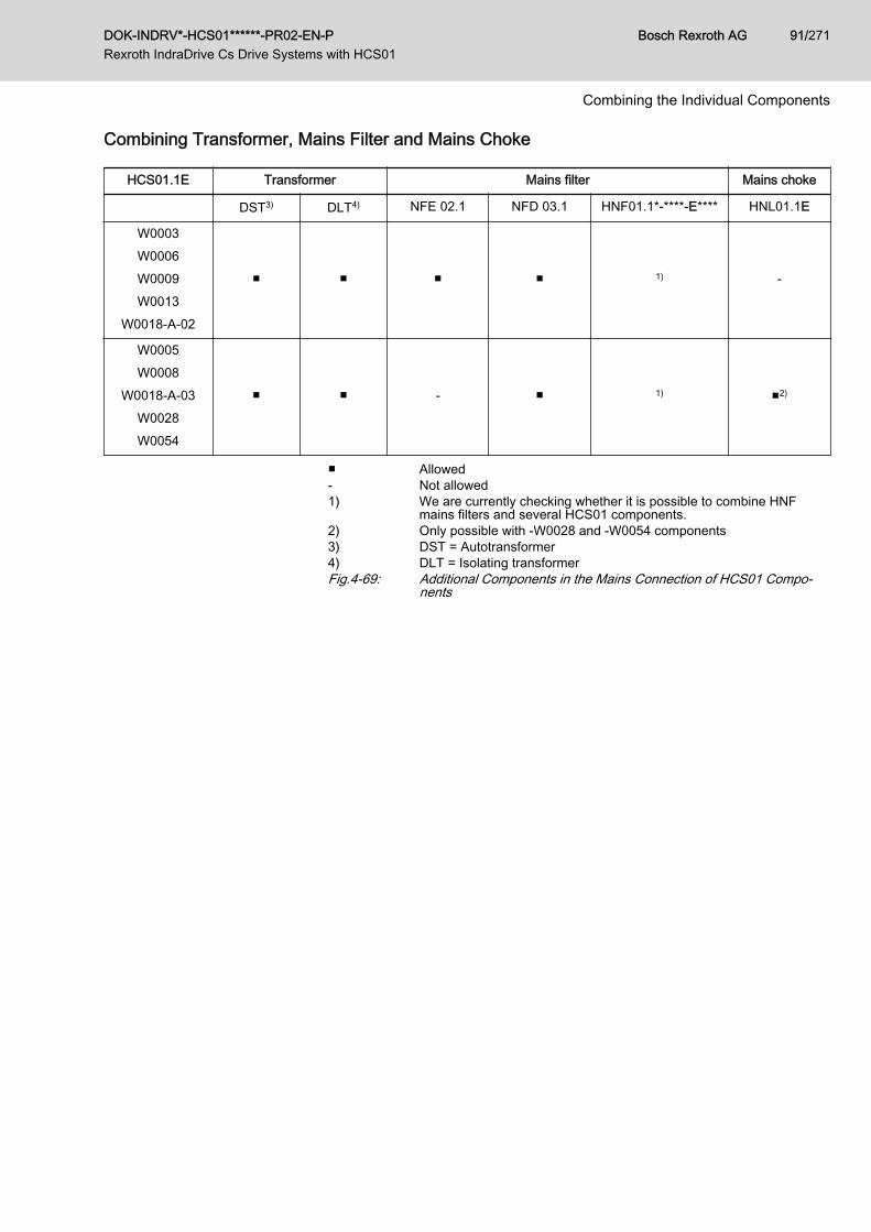
Combining Transformer, Mains Filter and Mains Choke
HCS01.1E Transformer Mains filter Mains choke
DST3) DLT4) NFE 02.1 NFD 03.1 HNF01.1*-****-E**** HNL01.1E
W0003W0006W0009W0013
W0018-A-02
■ ■ ■ ■ 1) -
W0005W0008
W0018-A-03W0028W0054
■ ■ - ■ 1) ■2)
■ Allowed- Not allowed1) We are currently checking whether it is possible to combine HNF
mains filters and several HCS01 components.2) Only possible with ‑W0028 and ‑W0054 components3) DST = Autotransformer4) DLT = Isolating transformerFig.4-69: Additional Components in the Mains Connection of HCS01 Compo‐
nents
DOK-INDRV*-HCS01******-PR02-EN-P Rexroth IndraDrive Cs Drive Systems with HCS01
Bosch Rexroth AG 91/271
Combining the Individual Components
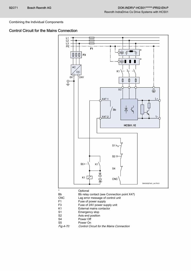
Control Circuit for the Mains Connection
* OptionalBb Bb relay contact (see Connection point X47)CNC Lag error message of control unitF1 Fuse of power supplyF3 Fuse of 24V power supply unitK1 External mains contactorS1 Emergency stopS2 Axis end positionS4 Power OffS5 Power OnFig.4-70: Control Circuit for the Mains Connection
Bosch Rexroth AG DOK-INDRV*-HCS01******-PR02-EN-P Rexroth IndraDrive Cs Drive Systems with HCS01
92/271
Combining the Individual Components
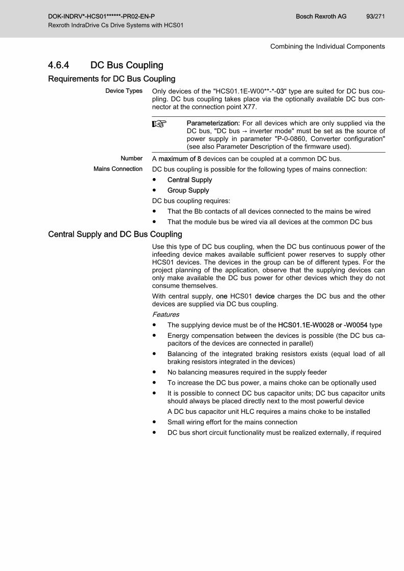
4.6.4 DC Bus CouplingRequirements for DC Bus Coupling
Device Types Only devices of the "HCS01.1E-W00**-*-03" type are suited for DC bus cou‐pling. DC bus coupling takes place via the optionally available DC bus con‐nector at the connection point X77.
Parameterization: For all devices which are only supplied via theDC bus, "DC bus → inverter mode" must be set as the source ofpower supply in parameter "P-0-0860, Converter configuration"(see also Parameter Description of the firmware used).
Number A maximum of 8 devices can be coupled at a common DC bus.Mains Connection DC bus coupling is possible for the following types of mains connection:
● Central Supply● Group SupplyDC bus coupling requires:● That the Bb contacts of all devices connected to the mains be wired● That the module bus be wired via all devices at the common DC bus
Central Supply and DC Bus CouplingUse this type of DC bus coupling, when the DC bus continuous power of theinfeeding device makes available sufficient power reserves to supply otherHCS01 devices. The devices in the group can be of different types. For theproject planning of the application, observe that the supplying devices canonly make available the DC bus power for other devices which they do notconsume themselves.With central supply, one HCS01 device charges the DC bus and the otherdevices are supplied via DC bus coupling.Features● The supplying device must be of the HCS01.1E-W0028 or ‑W0054 type● Energy compensation between the devices is possible (the DC bus ca‐
pacitors of the devices are connected in parallel)● Balancing of the integrated braking resistors exists (equal load of all
braking resistors integrated in the devices)● No balancing measures required in the supply feeder● To increase the DC bus power, a mains choke can be optionally used● It is possible to connect DC bus capacitor units; DC bus capacitor units
should always be placed directly next to the most powerful deviceA DC bus capacitor unit HLC requires a mains choke to be installed
● Small wiring effort for the mains connection● DC bus short circuit functionality must be realized externally, if required
DOK-INDRV*-HCS01******-PR02-EN-P Rexroth IndraDrive Cs Drive Systems with HCS01
Bosch Rexroth AG 93/271
Combining the Individual Components
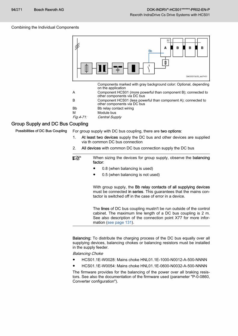
Components marked with gray background color: Optional, dependingon the application
A Component HCS01 (more powerful than component B); connected toother components via DC bus
B Component HCS01 (less powerful than component A); connected toother components via DC bus
Bb Bb relay contact wiringM Module busFig.4-71: Central Supply
Group Supply and DC Bus CouplingPossibilities of DC Bus Coupling For group supply with DC bus coupling, there are two options:
1. At least two devices supply the DC bus and other devices are suppliedvia th common DC bus connection
2. All devices with common DC bus connection supply the DC bus
When sizing the devices for group supply, observe the balancingfactor:● 0.8 (when balancing is used)● 0.5 (when balancing is not used) With group supply, the Bb relay contacts of all supplying devicesmust be connected in series. This guarantees that the mains con‐tactor is switched off in the case of error in a device. The lines of DC bus coupling mustn't be run outside of the controlcabinet. The maximum line length of a DC bus coupling is 2 m.See also description of the connection point X77 for more infor‐mation (see page 131).
Balancing: To distribute the charging process of the DC bus equally over allsupplying devices, balancing chokes or balancing resistors must be installedin the supply feeder.Balancing Choke● HCS01.1E-W0028: Mains choke HNL01.1E-1000-N0012-A-500-NNNN● HCS01.1E-W0054: Mains choke HNL01.1E-0600-N0032-A-500-NNNNThe firmware provides for the balancing of the power over all braking resis‐tors. See also the documentation of the firmware used (parameter "P-0-0860,Converter configuration").
Bosch Rexroth AG DOK-INDRV*-HCS01******-PR02-EN-P Rexroth IndraDrive Cs Drive Systems with HCS01
94/271
Combining the Individual Components
The parallel connection of the braking resistors causes derating/reduction of power of the continuous braking resistor power to thefactor 0.8.
Supply via at Least Two Devices Use this type of DC bus coupling if you use different HCS01 device types in
your application.
Components marked with gray background color: Optional, dependingon the application; the choke is used to reduce current harmonics
A Component HCS01 (more powerful than component B; all compo‐nents A identical); connected to supply mains via balancing chokes;connected to other components via DC bus
B Component HCS01 (less powerful than component A); connected toother components via DC bus
Bb Bb relay contact wiringM Module busFig.4-72: Group Supply; Several HCS01 Components Connected to Supply
MainsFeatures● The supplying devices1) 2) must be of the same type. The following devi‐
ces are suited as supplying devices:– HCS01.1E-W0028– HCS01.1E-W0054
● DC bus continuous power of the supplying devices reduced by paralleloperation
● Energy compensation between the devices is possible (the DC bus ca‐pacitors of the devices are connected in parallel)
● Balancing of the integrated braking resistors exists (equal load of allbraking resistors integrated in the devices)
● Balancing chokes or balancing resistors required in supply feeder● It is possible to connect DC bus capacitor units● Wiring effort for the mains connection relatively small● It is possible to use a common mains contactor, as well as a common
mains filter● DC bus short circuit functionality must be realized externally, if required
1) Supplying devices are devices connected to the mains which supply power to oth‐er devices via a DC bus connection
2) Supplied devices are devices not connected to the mains which are supplied withpower by the supplying devices via a DC bus connection
DOK-INDRV*-HCS01******-PR02-EN-P Rexroth IndraDrive Cs Drive Systems with HCS01
Bosch Rexroth AG 95/271
Combining the Individual Components
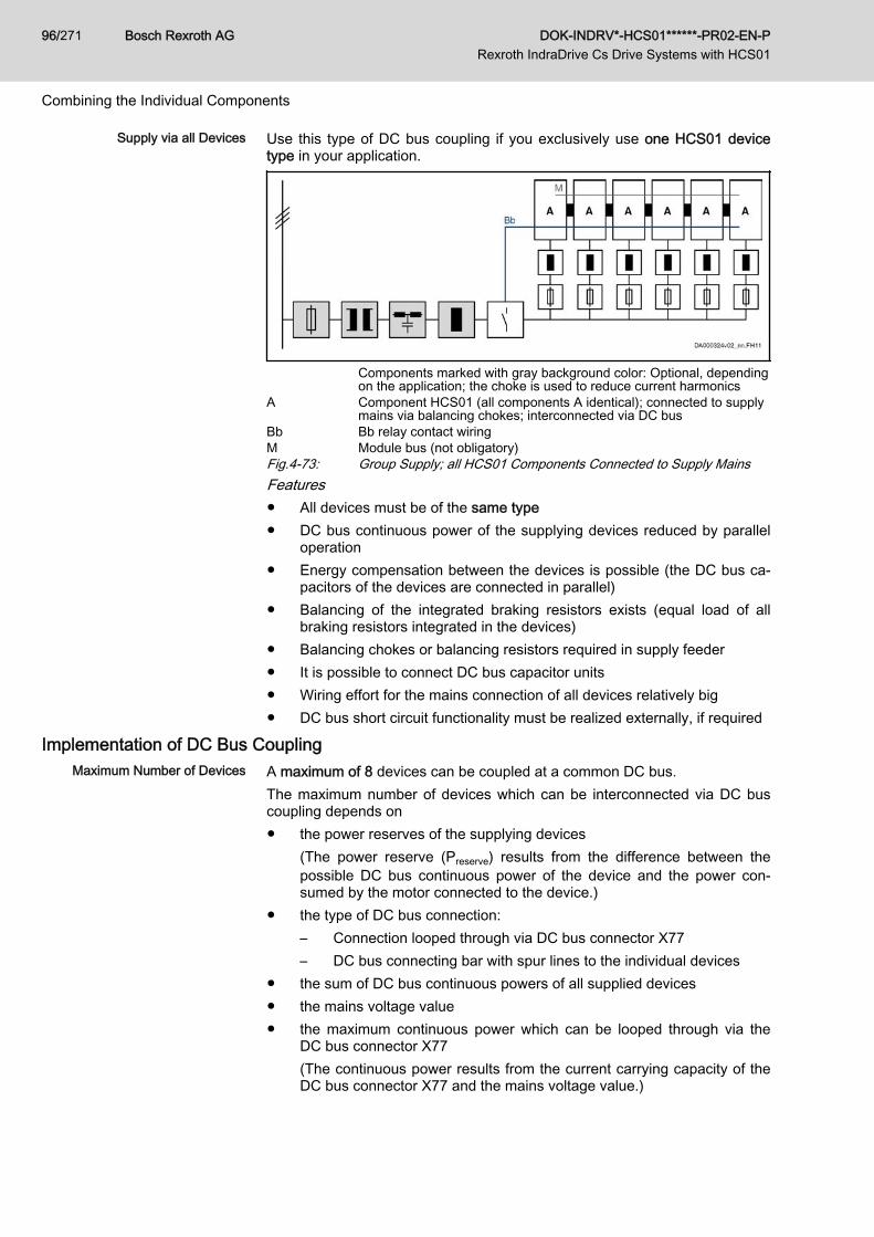
Supply via all Devices Use this type of DC bus coupling if you exclusively use one HCS01 devicetype in your application.
Components marked with gray background color: Optional, dependingon the application; the choke is used to reduce current harmonics
A Component HCS01 (all components A identical); connected to supplymains via balancing chokes; interconnected via DC bus
Bb Bb relay contact wiringM Module bus (not obligatory)Fig.4-73: Group Supply; all HCS01 Components Connected to Supply MainsFeatures● All devices must be of the same type● DC bus continuous power of the supplying devices reduced by parallel
operation● Energy compensation between the devices is possible (the DC bus ca‐
pacitors of the devices are connected in parallel)● Balancing of the integrated braking resistors exists (equal load of all
braking resistors integrated in the devices)● Balancing chokes or balancing resistors required in supply feeder● It is possible to connect DC bus capacitor units● Wiring effort for the mains connection of all devices relatively big● DC bus short circuit functionality must be realized externally, if required
Implementation of DC Bus CouplingMaximum Number of Devices A maximum of 8 devices can be coupled at a common DC bus.
The maximum number of devices which can be interconnected via DC buscoupling depends on● the power reserves of the supplying devices
(The power reserve (Preserve) results from the difference between thepossible DC bus continuous power of the device and the power con‐sumed by the motor connected to the device.)
● the type of DC bus connection:– Connection looped through via DC bus connector X77– DC bus connecting bar with spur lines to the individual devices
● the sum of DC bus continuous powers of all supplied devices● the mains voltage value● the maximum continuous power which can be looped through via the
DC bus connector X77(The continuous power results from the current carrying capacity of theDC bus connector X77 and the mains voltage value.)
Bosch Rexroth AG DOK-INDRV*-HCS01******-PR02-EN-P Rexroth IndraDrive Cs Drive Systems with HCS01
96/271
Combining the Individual Components
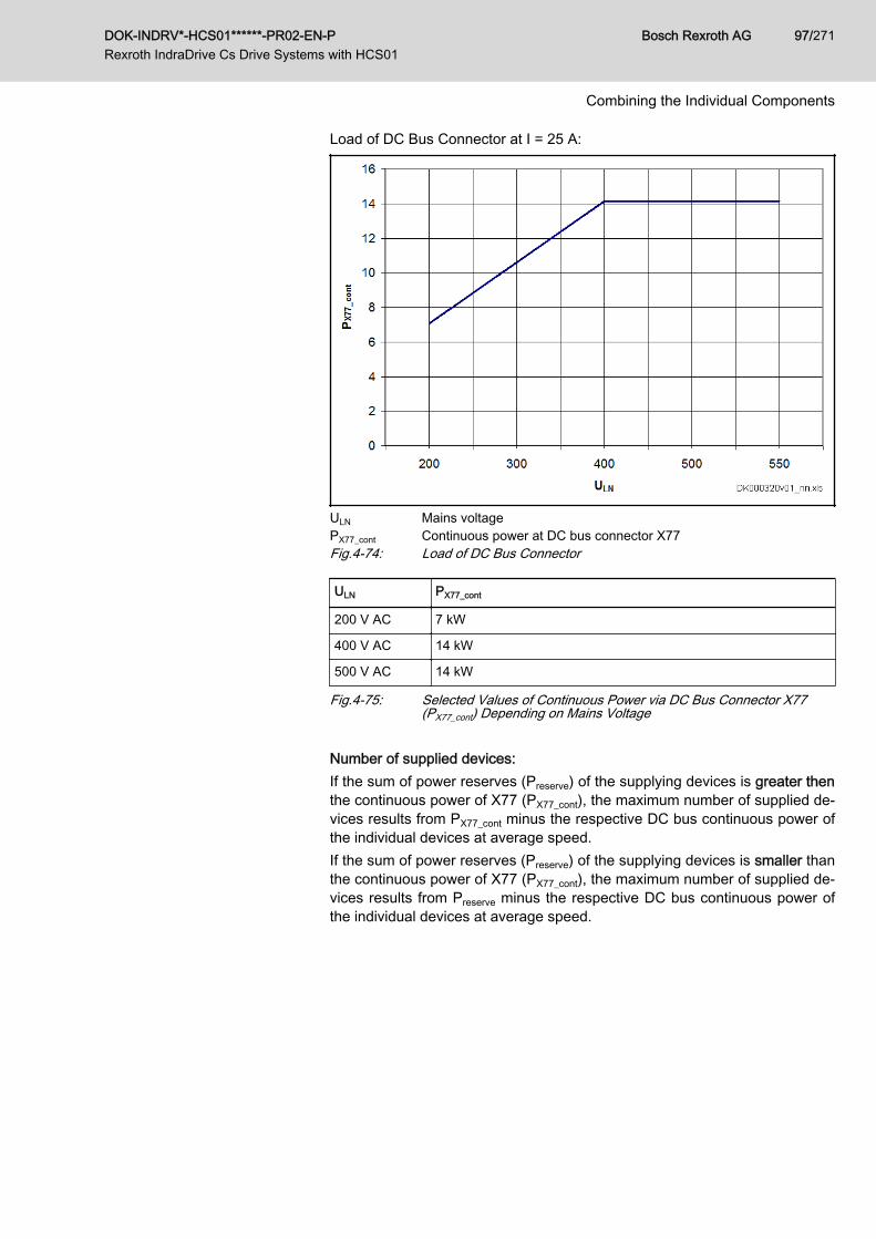
Load of DC Bus Connector at I = 25 A:
ULN Mains voltagePX77_cont Continuous power at DC bus connector X77Fig.4-74: Load of DC Bus Connector
ULN PX77_cont
200 V AC 7 kW
400 V AC 14 kW
500 V AC 14 kW
Fig.4-75: Selected Values of Continuous Power via DC Bus Connector X77(PX77_cont) Depending on Mains Voltage
Number of supplied devices:If the sum of power reserves (Preserve) of the supplying devices is greater thenthe continuous power of X77 (PX77_cont), the maximum number of supplied de‐vices results from PX77_cont minus the respective DC bus continuous power ofthe individual devices at average speed.If the sum of power reserves (Preserve) of the supplying devices is smaller thanthe continuous power of X77 (PX77_cont), the maximum number of supplied de‐vices results from Preserve minus the respective DC bus continuous power ofthe individual devices at average speed.
DOK-INDRV*-HCS01******-PR02-EN-P Rexroth IndraDrive Cs Drive Systems with HCS01
Bosch Rexroth AG 97/271
Combining the Individual Components
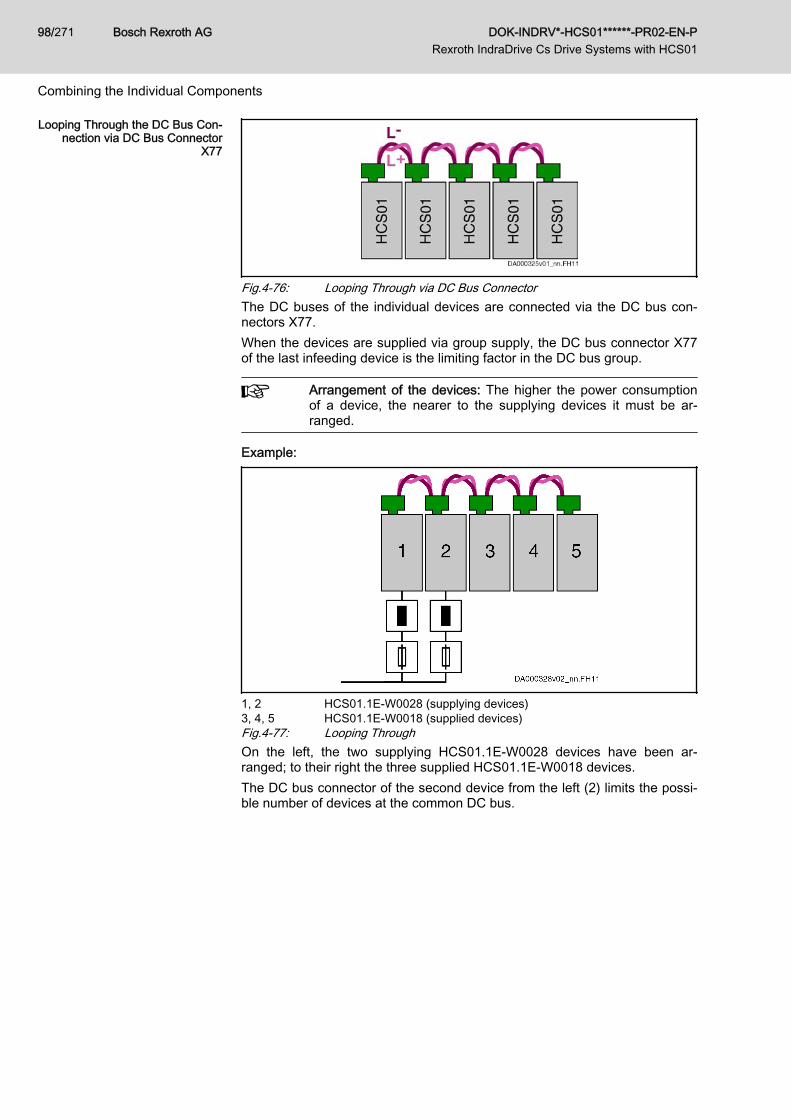
Looping Through the DC Bus Con‐nection via DC Bus Connector
X77
Fig.4-76: Looping Through via DC Bus ConnectorThe DC buses of the individual devices are connected via the DC bus con‐nectors X77.When the devices are supplied via group supply, the DC bus connector X77of the last infeeding device is the limiting factor in the DC bus group.
Arrangement of the devices: The higher the power consumptionof a device, the nearer to the supplying devices it must be ar‐ranged.
Example:
1, 2 HCS01.1E-W0028 (supplying devices)3, 4, 5 HCS01.1E-W0018 (supplied devices)Fig.4-77: Looping ThroughOn the left, the two supplying HCS01.1E-W0028 devices have been ar‐ranged; to their right the three supplied HCS01.1E-W0018 devices.The DC bus connector of the second device from the left (2) limits the possi‐ble number of devices at the common DC bus.
Bosch Rexroth AG DOK-INDRV*-HCS01******-PR02-EN-P Rexroth IndraDrive Cs Drive Systems with HCS01
98/271
Combining the Individual Components
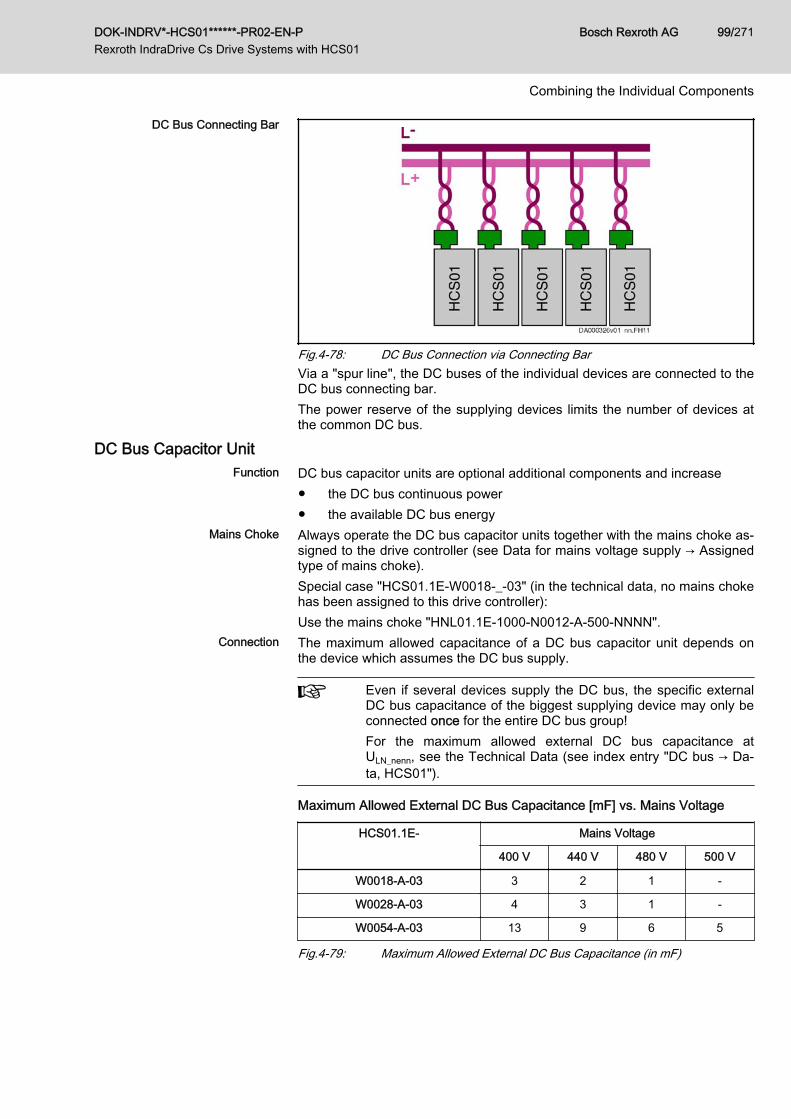
DC Bus Connecting Bar
Fig.4-78: DC Bus Connection via Connecting BarVia a "spur line", the DC buses of the individual devices are connected to theDC bus connecting bar.The power reserve of the supplying devices limits the number of devices atthe common DC bus.
DC Bus Capacitor UnitFunction DC bus capacitor units are optional additional components and increase
● the DC bus continuous power● the available DC bus energy
Mains Choke Always operate the DC bus capacitor units together with the mains choke as‐signed to the drive controller (see Data for mains voltage supply → Assignedtype of mains choke).Special case "HCS01.1E-W0018-_-03" (in the technical data, no mains chokehas been assigned to this drive controller):Use the mains choke "HNL01.1E-1000-N0012-A-500-NNNN".
Connection The maximum allowed capacitance of a DC bus capacitor unit depends onthe device which assumes the DC bus supply.
Even if several devices supply the DC bus, the specific externalDC bus capacitance of the biggest supplying device may only beconnected once for the entire DC bus group!For the maximum allowed external DC bus capacitance atULN_nenn, see the Technical Data (see index entry "DC bus → Da‐ta, HCS01").
Maximum Allowed External DC Bus Capacitance [mF] vs. Mains Voltage
HCS01.1E- Mains Voltage
400 V 440 V 480 V 500 V
W0018-A-03 3 2 1 -
W0028-A-03 4 3 1 -
W0054-A-03 13 9 6 5
Fig.4-79: Maximum Allowed External DC Bus Capacitance (in mF)
DOK-INDRV*-HCS01******-PR02-EN-P Rexroth IndraDrive Cs Drive Systems with HCS01
Bosch Rexroth AG 99/271
Combining the Individual Components
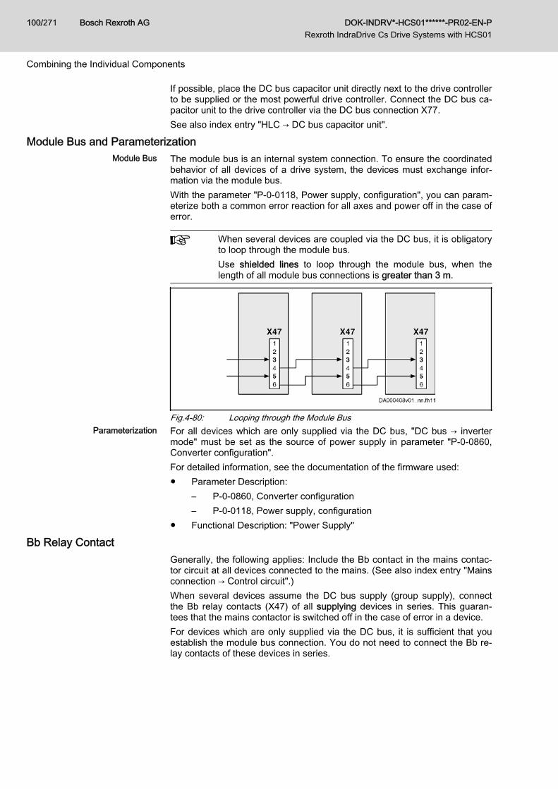
If possible, place the DC bus capacitor unit directly next to the drive controllerto be supplied or the most powerful drive controller. Connect the DC bus ca‐pacitor unit to the drive controller via the DC bus connection X77.See also index entry "HLC → DC bus capacitor unit".
Module Bus and ParameterizationModule Bus The module bus is an internal system connection. To ensure the coordinated
behavior of all devices of a drive system, the devices must exchange infor‐mation via the module bus.With the parameter "P-0-0118, Power supply, configuration", you can param‐eterize both a common error reaction for all axes and power off in the case oferror.
When several devices are coupled via the DC bus, it is obligatoryto loop through the module bus.Use shielded lines to loop through the module bus, when thelength of all module bus connections is greater than 3 m.
Fig.4-80: Looping through the Module BusParameterization For all devices which are only supplied via the DC bus, "DC bus → inverter
mode" must be set as the source of power supply in parameter "P-0-0860,Converter configuration".For detailed information, see the documentation of the firmware used:● Parameter Description:
– P-0-0860, Converter configuration– P-0-0118, Power supply, configuration
● Functional Description: "Power Supply"
Bb Relay ContactGenerally, the following applies: Include the Bb contact in the mains contac‐tor circuit at all devices connected to the mains. (See also index entry "Mainsconnection → Control circuit".)When several devices assume the DC bus supply (group supply), connectthe Bb relay contacts (X47) of all supplying devices in series. This guaran‐tees that the mains contactor is switched off in the case of error in a device.For devices which are only supplied via the DC bus, it is sufficient that youestablish the module bus connection. You do not need to connect the Bb re‐lay contacts of these devices in series.
Bosch Rexroth AG DOK-INDRV*-HCS01******-PR02-EN-P Rexroth IndraDrive Cs Drive Systems with HCS01
100/271
Combining the Individual Components
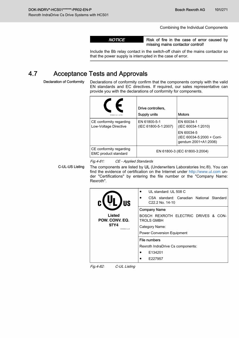
Risk of fire in the case of error caused bymissing mains contactor control!
NOTICE
Include the Bb relay contact in the switch-off chain of the mains contactor sothat the power supply is interrupted in the case of error.
4.7 Acceptance Tests and ApprovalsDeclaration of Conformity Declarations of conformity confirm that the components comply with the valid
EN standards and EC directives. If required, our sales representative canprovide you with the declarations of conformity for components.
Drive controllers,Supply units Motors
CE conformity regardingLow-Voltage Directive
EN 61800-5-1(IEC 61800‑5‑1:2007)
EN 60034-1(IEC 60034‑1:2010)EN 60034-5(IEC 60034‑5:2000 + Corri‐gendum 2001+A1:2006)
CE conformity regardingEMC product standard EN 61800-3 (IEC 61800‑3:2004)
Fig.4-81: CE - Applied StandardsC-UL-US Listing The components are listed by UL (Underwriters Laboratories Inc.®). You can
find the evidence of certification on the Internet under http://www.ul.com un‐der "Certifications" by entering the file number or the "Company Name:Rexroth".
● UL standard: UL 508 C● CSA standard: Canadian National Standard
C22.2 No. 14-10
Company NameBOSCH REXROTH ELECTRIC DRIVES & CON‐TROLS GMBHCategory Name:Power Conversion Equipment
File numbersRexroth IndraDrive Cs components:● E134201● E227957
Fig.4-82: C-UL Listing
DOK-INDRV*-HCS01******-PR02-EN-P Rexroth IndraDrive Cs Drive Systems with HCS01
Bosch Rexroth AG 101/271
Combining the Individual Components
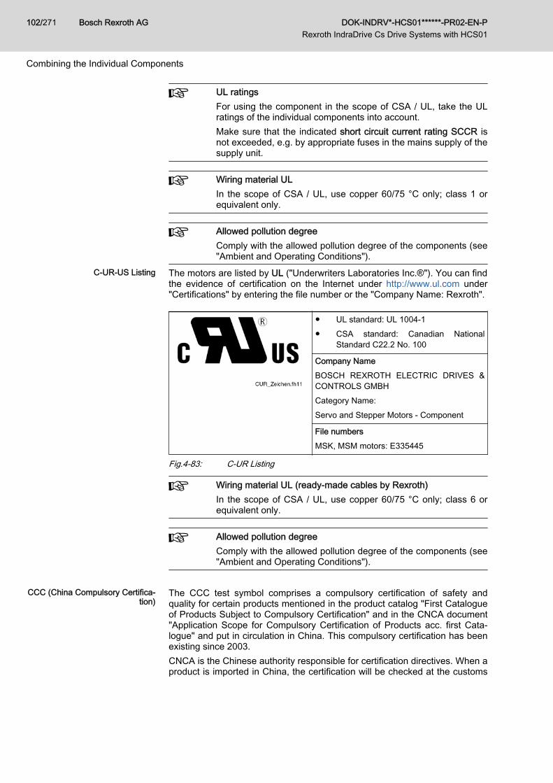
UL ratingsFor using the component in the scope of CSA / UL, take the ULratings of the individual components into account.Make sure that the indicated short circuit current rating SCCR isnot exceeded, e.g. by appropriate fuses in the mains supply of thesupply unit.
Wiring material ULIn the scope of CSA / UL, use copper 60/75 °C only; class 1 orequivalent only.
Allowed pollution degreeComply with the allowed pollution degree of the components (see"Ambient and Operating Conditions").
C-UR-US Listing The motors are listed by UL ("Underwriters Laboratories Inc.®"). You can findthe evidence of certification on the Internet under http://www.ul.com under"Certifications" by entering the file number or the "Company Name: Rexroth".
● UL standard: UL 1004-1● CSA standard: Canadian National
Standard C22.2 No. 100
Company NameBOSCH REXROTH ELECTRIC DRIVES &CONTROLS GMBHCategory Name:Servo and Stepper Motors - Component
File numbersMSK, MSM motors: E335445
Fig.4-83: C-UR Listing
Wiring material UL (ready-made cables by Rexroth)In the scope of CSA / UL, use copper 60/75 °C only; class 6 orequivalent only.
Allowed pollution degreeComply with the allowed pollution degree of the components (see"Ambient and Operating Conditions").
CCC (China Compulsory Certifica‐
tion)The CCC test symbol comprises a compulsory certification of safety andquality for certain products mentioned in the product catalog "First Catalogueof Products Subject to Compulsory Certification" and in the CNCA document"Application Scope for Compulsory Certification of Products acc. first Cata‐logue" and put in circulation in China. This compulsory certification has beenexisting since 2003.CNCA is the Chinese authority responsible for certification directives. When aproduct is imported in China, the certification will be checked at the customs
Bosch Rexroth AG DOK-INDRV*-HCS01******-PR02-EN-P Rexroth IndraDrive Cs Drive Systems with HCS01
102/271
Combining the Individual Components

by means of entries in a database. For the requirement of certification threecriteria are normally relevant:1. Customs tariff number (HS code) according to CNCA document "Appli‐
cation Scope for Compulsory Certification of Products acc. first Cata‐logue".
2. Scope of application according to CNCA document "Application Scopefor Compulsory Certification of Products acc. first Catalogue".
3. For the IEC product standard used, the corresponding Chinese GBstandard must exist.
For the drive components by Rexroth described in this documentation, certifi‐cation is not required at present, thus they are not CCC certified. Negativecertifications will not be issued.
DOK-INDRV*-HCS01******-PR02-EN-P Rexroth IndraDrive Cs Drive Systems with HCS01
Bosch Rexroth AG 103/271
Combining the Individual Components

Bosch Rexroth AG DOK-INDRV*-HCS01******-PR02-EN-P Rexroth IndraDrive Cs Drive Systems with HCS01
104/271
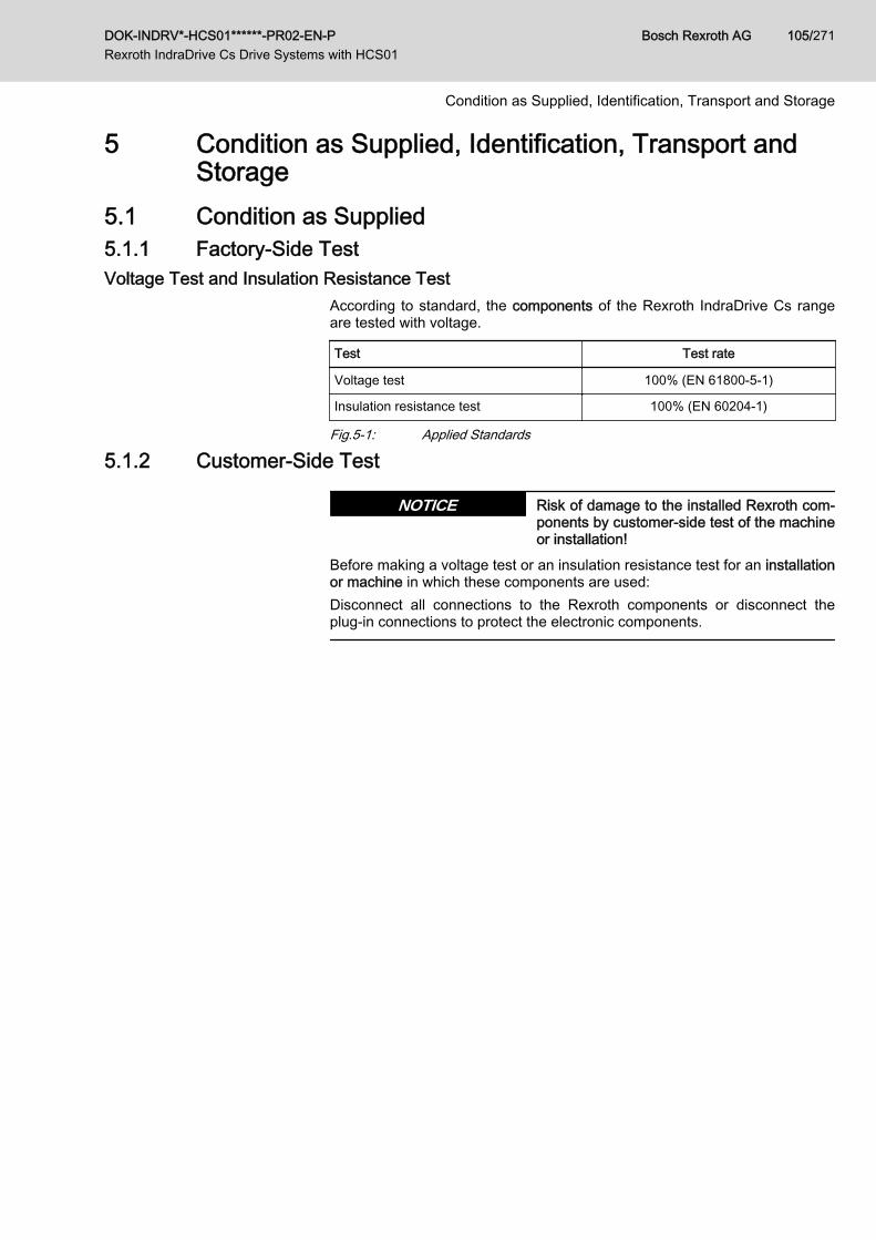
5 Condition as Supplied, Identification, Transport andStorage
5.1 Condition as Supplied5.1.1 Factory-Side TestVoltage Test and Insulation Resistance Test
According to standard, the components of the Rexroth IndraDrive Cs rangeare tested with voltage.
Test Test rate
Voltage test 100% (EN 61800-5-1)
Insulation resistance test 100% (EN 60204-1)
Fig.5-1: Applied Standards
5.1.2 Customer-Side Test
Risk of damage to the installed Rexroth com‐ponents by customer-side test of the machineor installation!
NOTICE
Before making a voltage test or an insulation resistance test for an installationor machine in which these components are used:Disconnect all connections to the Rexroth components or disconnect theplug-in connections to protect the electronic components.
DOK-INDRV*-HCS01******-PR02-EN-P Rexroth IndraDrive Cs Drive Systems with HCS01
Bosch Rexroth AG 105/271
Condition as Supplied, Identification, Transport and Storage
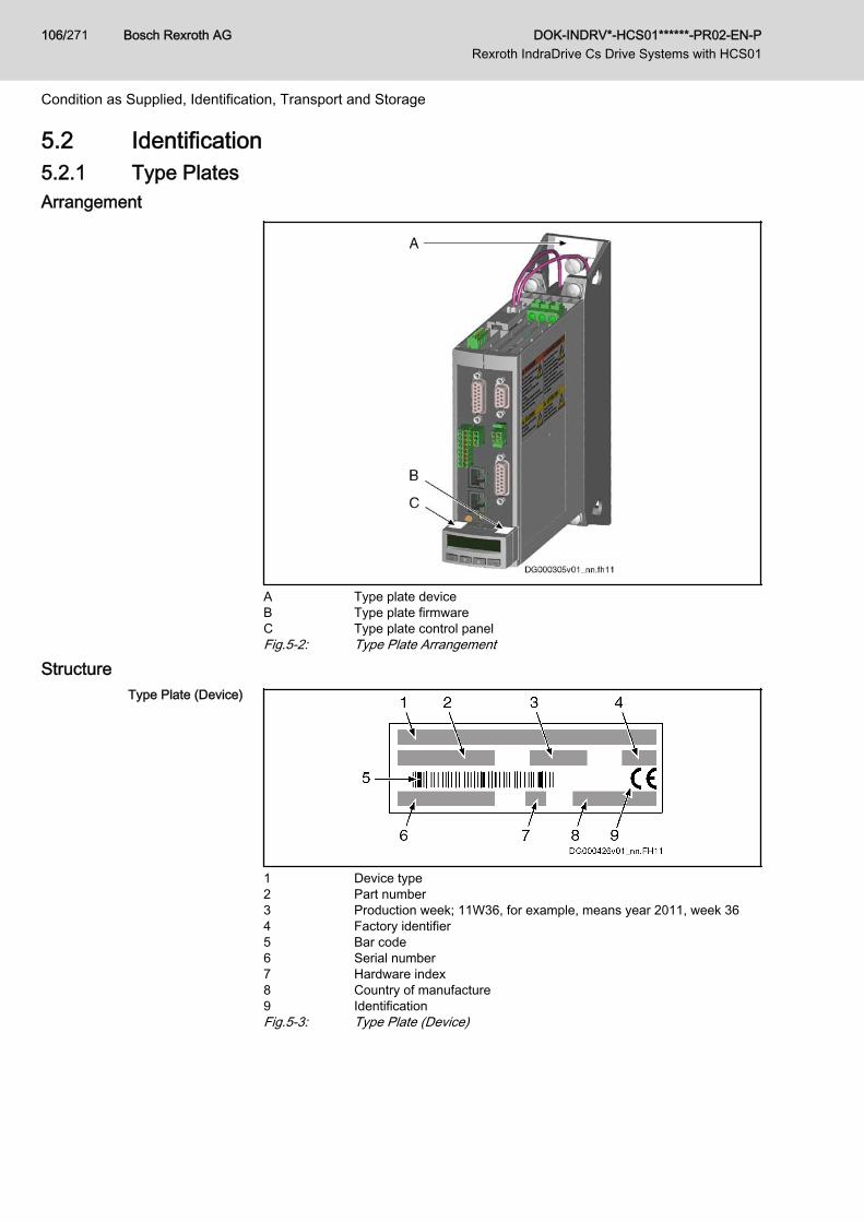
5.2 Identification5.2.1 Type PlatesArrangement
A Type plate deviceB Type plate firmwareC Type plate control panelFig.5-2: Type Plate Arrangement
StructureType Plate (Device)
1 Device type2 Part number3 Production week; 11W36, for example, means year 2011, week 364 Factory identifier5 Bar code6 Serial number7 Hardware index8 Country of manufacture9 IdentificationFig.5-3: Type Plate (Device)
Bosch Rexroth AG DOK-INDRV*-HCS01******-PR02-EN-P Rexroth IndraDrive Cs Drive Systems with HCS01
106/271
Condition as Supplied, Identification, Transport and Storage
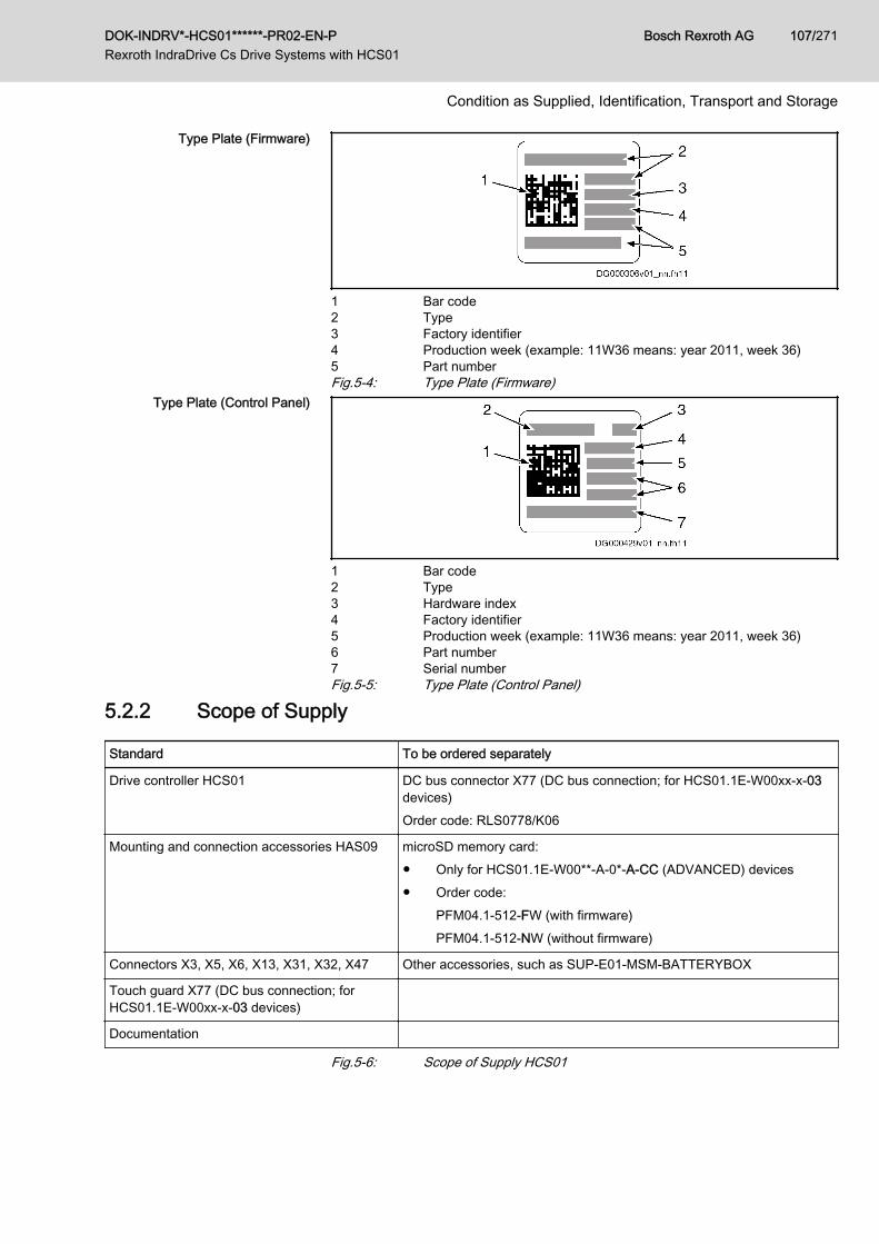
Type Plate (Firmware)
1 Bar code2 Type3 Factory identifier4 Production week (example: 11W36 means: year 2011, week 36)5 Part numberFig.5-4: Type Plate (Firmware)
Type Plate (Control Panel)
1 Bar code2 Type3 Hardware index4 Factory identifier5 Production week (example: 11W36 means: year 2011, week 36)6 Part number7 Serial numberFig.5-5: Type Plate (Control Panel)
5.2.2 Scope of Supply
Standard To be ordered separately
Drive controller HCS01 DC bus connector X77 (DC bus connection; for HCS01.1E-W00xx-x-03devices)Order code: RLS0778/K06
Mounting and connection accessories HAS09 microSD memory card:● Only for HCS01.1E-W00**-A-0*-A-CC (ADVANCED) devices● Order code:
PFM04.1-512-FW (with firmware)PFM04.1-512-NW (without firmware)
Connectors X3, X5, X6, X13, X31, X32, X47 Other accessories, such as SUP-E01-MSM-BATTERYBOX
Touch guard X77 (DC bus connection; forHCS01.1E-W00xx-x-03 devices)
Documentation
Fig.5-6: Scope of Supply HCS01
DOK-INDRV*-HCS01******-PR02-EN-P Rexroth IndraDrive Cs Drive Systems with HCS01
Bosch Rexroth AG 107/271
Condition as Supplied, Identification, Transport and Storage
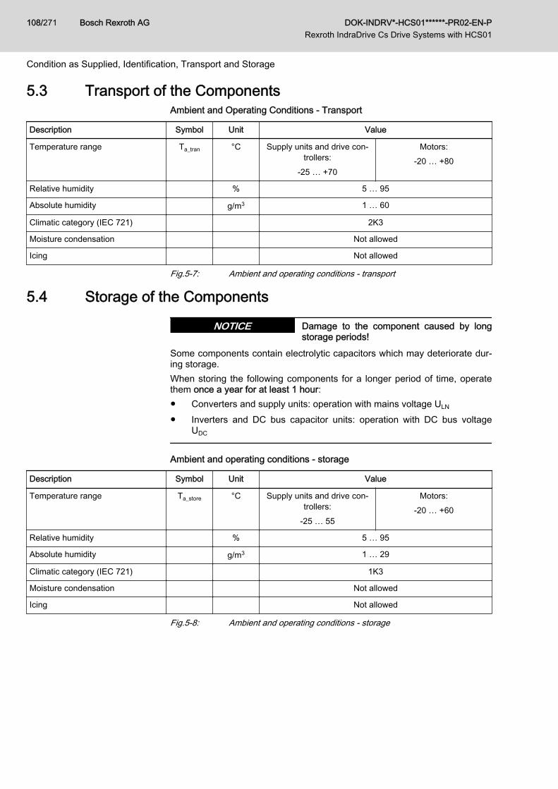
5.3 Transport of the ComponentsAmbient and Operating Conditions - Transport
Description Symbol Unit Value
Temperature range Ta_tran °C Supply units and drive con‐trollers:
-25 … +70
Motors:-20 … +80
Relative humidity % 5 … 95
Absolute humidity g/m3 1 … 60
Climatic category (IEC 721) 2K3
Moisture condensation Not allowed
Icing Not allowed
Fig.5-7: Ambient and operating conditions - transport
5.4 Storage of the Components
Damage to the component caused by longstorage periods!
NOTICE
Some components contain electrolytic capacitors which may deteriorate dur‐ing storage.When storing the following components for a longer period of time, operatethem once a year for at least 1 hour:● Converters and supply units: operation with mains voltage ULN
● Inverters and DC bus capacitor units: operation with DC bus voltageUDC
Ambient and operating conditions - storage
Description Symbol Unit Value
Temperature range Ta_store °C Supply units and drive con‐trollers:
-25 … 55
Motors:-20 … +60
Relative humidity % 5 … 95
Absolute humidity g/m3 1 … 29
Climatic category (IEC 721) 1K3
Moisture condensation Not allowed
Icing Not allowed
Fig.5-8: Ambient and operating conditions - storage
Bosch Rexroth AG DOK-INDRV*-HCS01******-PR02-EN-P Rexroth IndraDrive Cs Drive Systems with HCS01
108/271
Condition as Supplied, Identification, Transport and Storage
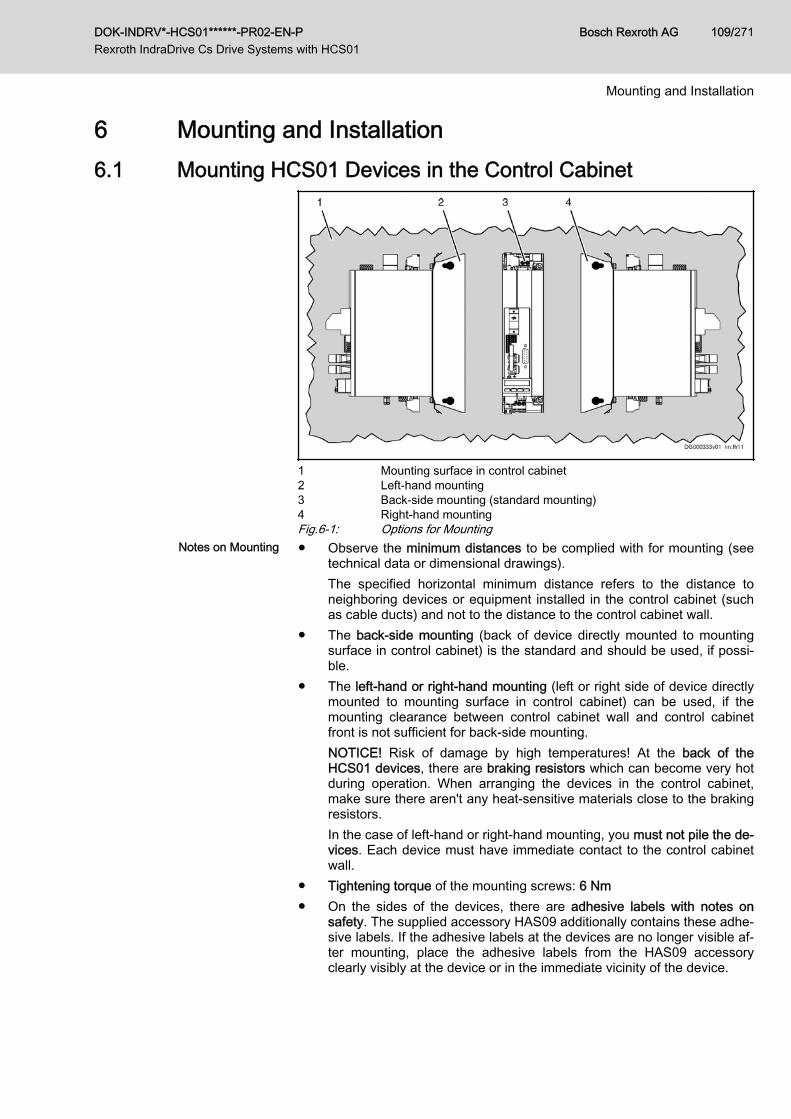
6 Mounting and Installation6.1 Mounting HCS01 Devices in the Control Cabinet
1 Mounting surface in control cabinet2 Left-hand mounting3 Back-side mounting (standard mounting)4 Right-hand mountingFig.6-1: Options for Mounting
Notes on Mounting ● Observe the minimum distances to be complied with for mounting (seetechnical data or dimensional drawings).The specified horizontal minimum distance refers to the distance toneighboring devices or equipment installed in the control cabinet (suchas cable ducts) and not to the distance to the control cabinet wall.
● The back-side mounting (back of device directly mounted to mountingsurface in control cabinet) is the standard and should be used, if possi‐ble.
● The left-hand or right-hand mounting (left or right side of device directlymounted to mounting surface in control cabinet) can be used, if themounting clearance between control cabinet wall and control cabinetfront is not sufficient for back-side mounting.NOTICE! Risk of damage by high temperatures! At the back of theHCS01 devices, there are braking resistors which can become very hotduring operation. When arranging the devices in the control cabinet,make sure there aren't any heat-sensitive materials close to the brakingresistors.In the case of left-hand or right-hand mounting, you must not pile the de‐vices. Each device must have immediate contact to the control cabinetwall.
● Tightening torque of the mounting screws: 6 Nm● On the sides of the devices, there are adhesive labels with notes on
safety. The supplied accessory HAS09 additionally contains these adhe‐sive labels. If the adhesive labels at the devices are no longer visible af‐ter mounting, place the adhesive labels from the HAS09 accessoryclearly visibly at the device or in the immediate vicinity of the device.
DOK-INDRV*-HCS01******-PR02-EN-P Rexroth IndraDrive Cs Drive Systems with HCS01
Bosch Rexroth AG 109/271
Mounting and Installation
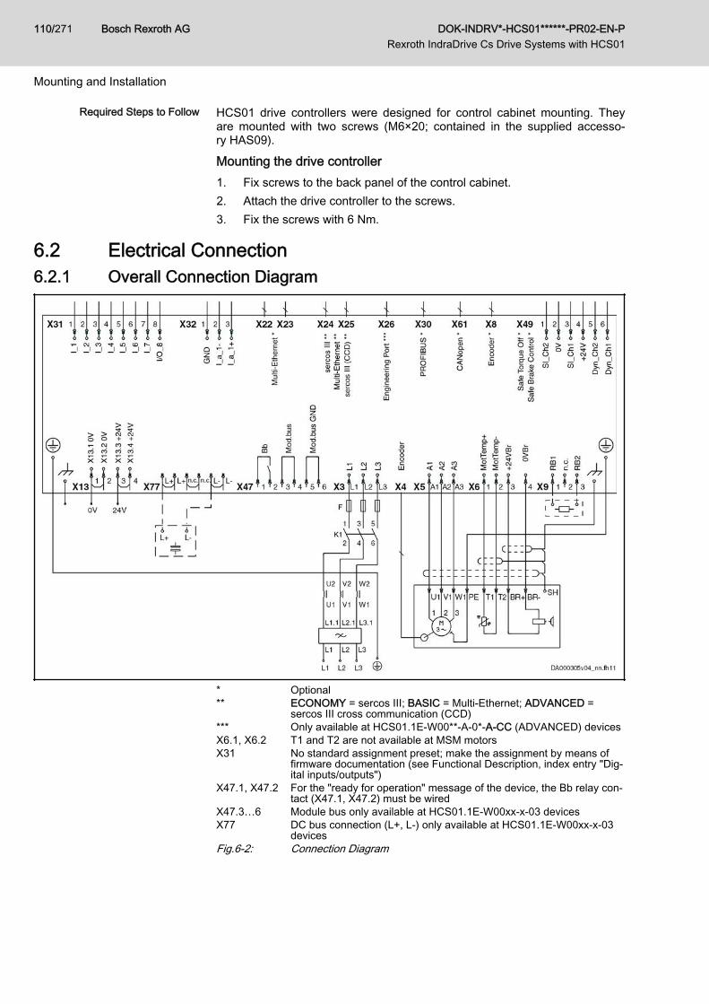
Required Steps to Follow HCS01 drive controllers were designed for control cabinet mounting. Theyare mounted with two screws (M6×20; contained in the supplied accesso‐ry HAS09).
Mounting the drive controller1. Fix screws to the back panel of the control cabinet.2. Attach the drive controller to the screws.3. Fix the screws with 6 Nm.
6.2 Electrical Connection6.2.1 Overall Connection Diagram
* Optional** ECONOMY = sercos III; BASIC = Multi-Ethernet; ADVANCED =
sercos III cross communication (CCD)*** Only available at HCS01.1E-W00**-A-0*-A-CC (ADVANCED) devicesX6.1, X6.2 T1 and T2 are not available at MSM motorsX31 No standard assignment preset; make the assignment by means of
firmware documentation (see Functional Description, index entry "Dig‐ital inputs/outputs")
X47.1, X47.2 For the "ready for operation" message of the device, the Bb relay con‐tact (X47.1, X47.2) must be wired
X47.3…6 Module bus only available at HCS01.1E-W00xx-x-03 devicesX77 DC bus connection (L+, L-) only available at HCS01.1E‑W00xx‑x‑03
devicesFig.6-2: Connection Diagram
Bosch Rexroth AG DOK-INDRV*-HCS01******-PR02-EN-P Rexroth IndraDrive Cs Drive Systems with HCS01
110/271
Mounting and Installation
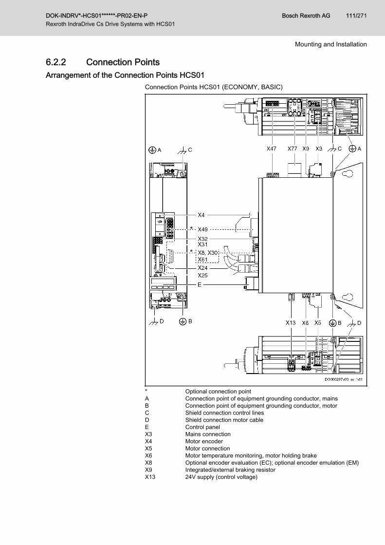
6.2.2 Connection PointsArrangement of the Connection Points HCS01
Connection Points HCS01 (ECONOMY, BASIC)
* Optional connection pointA Connection point of equipment grounding conductor, mainsB Connection point of equipment grounding conductor, motorC Shield connection control linesD Shield connection motor cableE Control panelX3 Mains connectionX4 Motor encoderX5 Motor connectionX6 Motor temperature monitoring, motor holding brakeX8 Optional encoder evaluation (EC); optional encoder emulation (EM)X9 Integrated/external braking resistorX13 24V supply (control voltage)
DOK-INDRV*-HCS01******-PR02-EN-P Rexroth IndraDrive Cs Drive Systems with HCS01
Bosch Rexroth AG 111/271
Mounting and Installation

X24 / X25 ECONOMY: Communication sercos III; BASIC: Communication Multi-Ethernet
X30 Optional communication PROFIBUS (PB)X31 Digital inputs, digital outputX32 Analog inputX47 Bb relay contact, module bus (module bus only at HCS01.1E-W00xx-
x-03 devices)X49 Optional safety technology (L3: "Safe Torque Off"; L4: "Safe Torque
Off", "Safe Brake Control")X61 Optional communication CANopen (CN)X77 DC bus connection (only at HCS01.1E-W00xx-x-03 devices); DC bus
connector optionally available (if the DC bus connector is not used,the DC bus connection must be covered with the supplied touchguard)
Fig.6-3: Connection Points HCS01
Bosch Rexroth AG DOK-INDRV*-HCS01******-PR02-EN-P Rexroth IndraDrive Cs Drive Systems with HCS01
112/271
Mounting and Installation
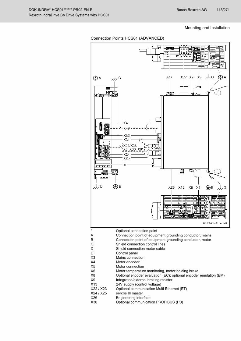
Connection Points HCS01 (ADVANCED)
* Optional connection pointA Connection point of equipment grounding conductor, mainsB Connection point of equipment grounding conductor, motorC Shield connection control linesD Shield connection motor cableE Control panelX3 Mains connectionX4 Motor encoderX5 Motor connectionX6 Motor temperature monitoring, motor holding brakeX8 Optional encoder evaluation (EC); optional encoder emulation (EM)X9 Integrated/external braking resistorX13 24V supply (control voltage)X22 / X23 Optional communication Multi-Ethernet (ET)X24 / X25 sercos III masterX26 Engineering interfaceX30 Optional communication PROFIBUS (PB)
DOK-INDRV*-HCS01******-PR02-EN-P Rexroth IndraDrive Cs Drive Systems with HCS01
Bosch Rexroth AG 113/271
Mounting and Installation
X31 Digital inputs, digital outputX32 Analog inputX47 Bb relay contact, module bus (module bus only at HCS01.1E-W00xx-
x-03 devices)X49 Optional safety technology (L3: "Safe Torque Off"; L4: "Safe Torque
Off", "Safe Brake Control")X61 Optional communication CANopen (CN)X77 DC bus connection (only at HCS01.1E-W00xx-x-03 devices); DC bus
connector optionally available (if the DC bus connector is not used,the DC bus connection must be covered with the supplied touchguard)
Fig.6-4:
6.2.3 On-Board Connection PointsConnection of Equipment Grounding Conductor
High housing voltage and high leakage cur‐rent! Danger to life, risk of injury by electricshock!
WARNING
● Before switching on and before commissioning, ground or connect thecomponents of the electric drive and control system to the equipmentgrounding conductor at the grounding points.
● Connect the equipment grounding conductor of the components of theelectric drive and control system permanently to the main power supplyat all times. The leakage current is greater than 3.5 mA.
● Establish an equipment grounding connection with a copper wire of across section of at least 10 mm2 (8 AWG) or additionally run a secondequipment grounding conductor of the same cross section as the origi‐nal equipment grounding conductor.
Lethal electric shock by live parts with morethan 50 V!
WARNING
Exclusively operate the device● with plugged on connectors (even if there haven't been any lines con‐
nected to the connectors) and● with connected equipment grounding conductor!
Equipment grounding conductor: Material and cross sectionFor the equipment grounding conductor, use the same metal (e.g.copper) as for the outer conductors.For the connections from the equipment grounding conductorconnection of the device to the equipment grounding conductorsystem in the control cabinet, make sure the cross sections of thelines are sufficient.Cross sections of the equipment grounding connections:For HCS01 drive controllers, at least 10 mm2, but not smaller thanthe cross sections of the outer conductors of the mains supplyfeeder.Additionally, mount the housing to a bare metal mounting plate.Connect the mounting plate, too, with at least the same crosssection to the equipment grounding conductor system in the con‐trol cabinet.
Bosch Rexroth AG DOK-INDRV*-HCS01******-PR02-EN-P Rexroth IndraDrive Cs Drive Systems with HCS01
114/271
Mounting and Installation
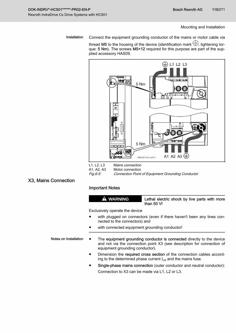
Installation Connect the equipment grounding conductor of the mains or motor cable via
thread M5 to the housing of the device (identification mark ; tightening tor‐que: 5 Nm). The screws M5×12 required for this purpose are part of the sup‐plied accessory HAS09.
L1, L2, L3 Mains connectionA1, A2, A3 Motor connectionFig.6-5: Connection Point of Equipment Grounding Conductor
X3, Mains ConnectionImportant Notes
Lethal electric shock by live parts with morethan 50 V!
WARNING
Exclusively operate the device● with plugged on connectors (even if there haven't been any lines con‐
nected to the connectors) and● with connected equipment grounding conductor!
Notes on Installation ● The equipment grounding conductor is connected directly to the deviceand not via the connection point X3 (see description for connection ofequipment grounding conductor).
● Dimension the required cross section of the connection cables accord‐ing to the determined phase current ILN and the mains fuse.
● Single-phase mains connection (outer conductor and neutral conductor):Connection to X3 can be made via L1, L2 or L3.
DOK-INDRV*-HCS01******-PR02-EN-P Rexroth IndraDrive Cs Drive Systems with HCS01
Bosch Rexroth AG 115/271
Mounting and Installation
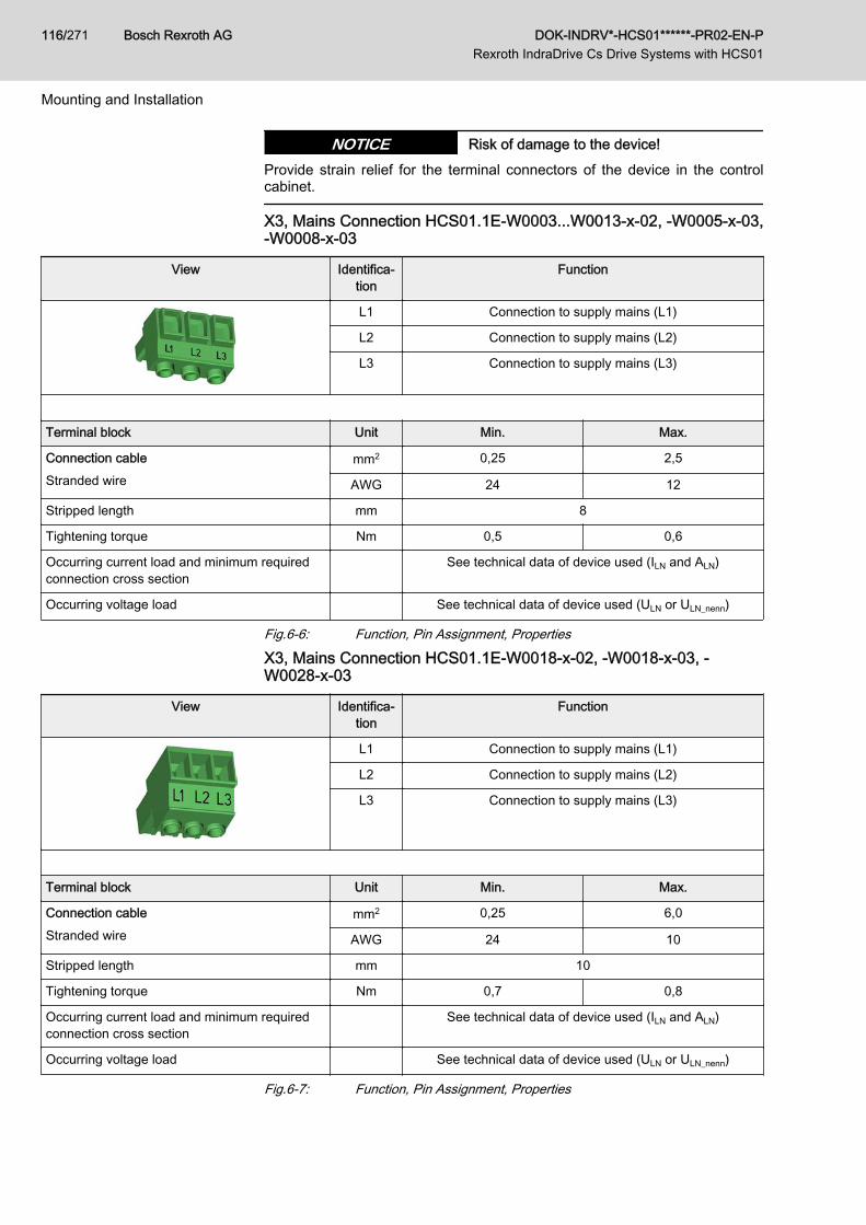
Risk of damage to the device!NOTICEProvide strain relief for the terminal connectors of the device in the controlcabinet.
X3, Mains Connection HCS01.1E-W0003...W0013-x-02, -W0005-x-03,-W0008-x-03
View Identifica‐tion
Function
L1 Connection to supply mains (L1)
L2 Connection to supply mains (L2)
L3 Connection to supply mains (L3)
Terminal block Unit Min. Max.
Connection cableStranded wire
mm2 0,25 2,5
AWG 24 12
Stripped length mm 8
Tightening torque Nm 0,5 0,6
Occurring current load and minimum requiredconnection cross section
See technical data of device used (ILN and ALN)
Occurring voltage load See technical data of device used (ULN or ULN_nenn)
Fig.6-6: Function, Pin Assignment, Properties
X3, Mains Connection HCS01.1E-W0018-x-02, -W0018-x-03, -W0028-x-03
View Identifica‐tion
Function
L1 Connection to supply mains (L1)
L2 Connection to supply mains (L2)
L3 Connection to supply mains (L3)
Terminal block Unit Min. Max.
Connection cableStranded wire
mm2 0,25 6,0
AWG 24 10
Stripped length mm 10
Tightening torque Nm 0,7 0,8
Occurring current load and minimum requiredconnection cross section
See technical data of device used (ILN and ALN)
Occurring voltage load See technical data of device used (ULN or ULN_nenn)
Fig.6-7: Function, Pin Assignment, Properties
Bosch Rexroth AG DOK-INDRV*-HCS01******-PR02-EN-P Rexroth IndraDrive Cs Drive Systems with HCS01
116/271
Mounting and Installation
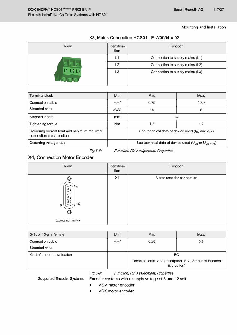
X3, Mains Connection HCS01.1E-W0054-x-03
View Identifica‐tion
Function
L1 Connection to supply mains (L1)
L2 Connection to supply mains (L2)
L3 Connection to supply mains (L3)
Terminal block Unit Min. Max.
Connection cableStranded wire
mm2 0,75 10,0
AWG 18 8
Stripped length mm 14
Tightening torque Nm 1,5 1,7
Occurring current load and minimum requiredconnection cross section
See technical data of device used (ILN and ALN)
Occurring voltage load See technical data of device used (ULN or ULN_nenn)
Fig.6-8: Function, Pin Assignment, Properties
X4, Connection Motor EncoderView Identifica‐
tionFunction
X4 Motor encoder connection
D-Sub, 15-pin, female Unit Min. Max.
Connection cableStranded wire
mm2 0,25 0,5
Kind of encoder evaluation ECTechnical data: See description "EC - Standard Encoder
Evaluation"
Fig.6-9: Function, Pin Assignment, PropertiesSupported Encoder Systems Encoder systems with a supply voltage of 5 and 12 volt
● MSM motor encoder● MSK motor encoder
DOK-INDRV*-HCS01******-PR02-EN-P Rexroth IndraDrive Cs Drive Systems with HCS01
Bosch Rexroth AG 117/271
Mounting and Installation
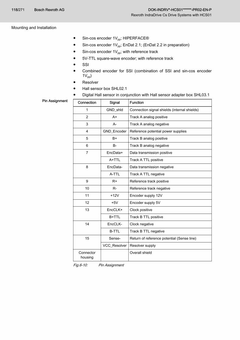
● Sin-cos encoder 1Vpp; HIPERFACE®● Sin-cos encoder 1Vpp; EnDat 2.1; (EnDat 2.2 in preparation)● Sin-cos encoder 1Vpp; with reference track● 5V-TTL square-wave encoder; with reference track● SSI● Combined encoder for SSI (combination of SSI and sin-cos encoder
1Vpp)● Resolver● Hall sensor box SHL02.1● Digital Hall sensor in conjunction with Hall sensor adapter box SHL03.1
Pin Assignment Connection Signal Function
1 GND_shld Connection signal shields (internal shields)
2 A+ Track A analog positive
3 A- Track A analog negative
4 GND_Encoder Reference potential power supplies
5 B+ Track B analog positive
6 B- Track B analog negative
7 EncData+ Data transmission positive
A+TTL Track A TTL positive
8 EncData- Data transmission negative
A-TTL Track A TTL negative
9 R+ Reference track positive
10 R- Reference track negative
11 +12V Encoder supply 12V
12 +5V Encoder supply 5V
13 EncCLK+ Clock positive
B+TTL Track B TTL positive
14 EncCLK- Clock negative
B-TTL Track B TTL negative
15 Sense- Return of reference potential (Sense line)
VCC_Resolver Resolver supply
Connectorhousing Overall shield
Fig.6-10: Pin Assignment
Bosch Rexroth AG DOK-INDRV*-HCS01******-PR02-EN-P Rexroth IndraDrive Cs Drive Systems with HCS01
118/271
Mounting and Installation
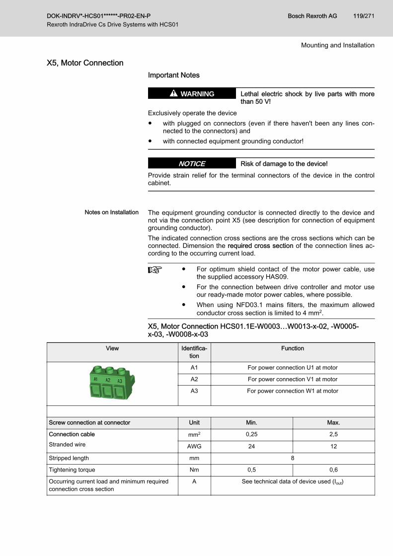
X5, Motor ConnectionImportant Notes
Lethal electric shock by live parts with morethan 50 V!
WARNING
Exclusively operate the device● with plugged on connectors (even if there haven't been any lines con‐
nected to the connectors) and● with connected equipment grounding conductor!
Risk of damage to the device!NOTICEProvide strain relief for the terminal connectors of the device in the controlcabinet.
Notes on Installation The equipment grounding conductor is connected directly to the device and
not via the connection point X5 (see description for connection of equipmentgrounding conductor).The indicated connection cross sections are the cross sections which can beconnected. Dimension the required cross section of the connection lines ac‐cording to the occurring current load.
● For optimum shield contact of the motor power cable, usethe supplied accessory HAS09.
● For the connection between drive controller and motor useour ready-made motor power cables, where possible.
● When using NFD03.1 mains filters, the maximum allowedconductor cross section is limited to 4 mm2.
X5, Motor Connection HCS01.1E-W0003…W0013-x-02, -W0005-x-03, -W0008-x-03
View Identifica‐tion
Function
A1 For power connection U1 at motor
A2 For power connection V1 at motor
A3 For power connection W1 at motor
Screw connection at connector Unit Min. Max.
Connection cableStranded wire
mm2 0,25 2,5
AWG 24 12
Stripped length mm 8
Tightening torque Nm 0,5 0,6
Occurring current load and minimum requiredconnection cross section
A See technical data of device used (Iout)
DOK-INDRV*-HCS01******-PR02-EN-P Rexroth IndraDrive Cs Drive Systems with HCS01
Bosch Rexroth AG 119/271
Mounting and Installation
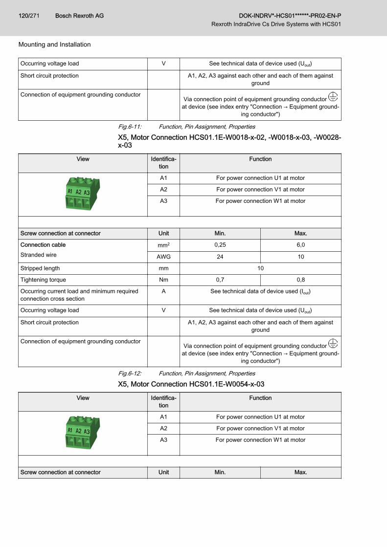
Occurring voltage load V See technical data of device used (Uout)
Short circuit protection A1, A2, A3 against each other and each of them againstground
Connection of equipment grounding conductor Via connection point of equipment grounding conductor
at device (see index entry "Connection → Equipment ground‐ing conductor")
Fig.6-11: Function, Pin Assignment, Properties
X5, Motor Connection HCS01.1E-W0018-x-02, -W0018-x-03, -W0028-x-03
View Identifica‐tion
Function
A1 For power connection U1 at motor
A2 For power connection V1 at motor
A3 For power connection W1 at motor
Screw connection at connector Unit Min. Max.
Connection cableStranded wire
mm2 0,25 6,0
AWG 24 10
Stripped length mm 10
Tightening torque Nm 0,7 0,8
Occurring current load and minimum requiredconnection cross section
A See technical data of device used (Iout)
Occurring voltage load V See technical data of device used (Uout)
Short circuit protection A1, A2, A3 against each other and each of them againstground
Connection of equipment grounding conductor Via connection point of equipment grounding conductor
at device (see index entry "Connection → Equipment ground‐ing conductor")
Fig.6-12: Function, Pin Assignment, Properties
X5, Motor Connection HCS01.1E-W0054-x-03
View Identifica‐tion
Function
A1 For power connection U1 at motor
A2 For power connection V1 at motor
A3 For power connection W1 at motor
Screw connection at connector Unit Min. Max.
Bosch Rexroth AG DOK-INDRV*-HCS01******-PR02-EN-P Rexroth IndraDrive Cs Drive Systems with HCS01
120/271
Mounting and Installation

Connection cableStranded wire
mm2 0,75 10,0
AWG 18 8
Stripped length mm 14
Tightening torque Nm 1,5 1,7
Occurring current load and minimum requiredconnection cross section
A See technical data of device used (Iout)
Occurring voltage load V See technical data of device used (Uout)
Short circuit protection A1, A2, A3 against each other and each of them againstground
Connection of equipment grounding conductor Via connection point of equipment grounding conductor
at device (see index entry "Connection → Equipment ground‐ing conductor")
Fig.6-13: Function, Pin Assignment, Properties
X6, Motor Temperature Monitoring and Motor Holding Brake
Dangerous movements! Danger to personsfrom falling or dropping axes!
WARNING
The standard motor holding brake provided or an external motor holdingbrake controlled directly by the drive controller are not sufficient on their ownto guarantee personal safety!Personal safety must be achieved using higher-level, fail-safe measures:● Block off danger zones with safety fences or safety guards● Additionally secure vertical axes against falling or dropping after switch‐
ing off the motor power by, for example,– mechanically securing the vertical axes– adding external braking/arrester/clamping mechanisms– ensuring sufficient equilibration of the vertical axes
Lethal electric shock by live parts with morethan 50 V!
WARNING
The input of the motor temperature evaluation is not galvanically isolatedfrom the housing. If the voltage applied to the input is impermissibly high (e.g.because of a flashover of the motor winding voltage), this voltage may comeinto contact with the housing. Ensure that the temperature sensor of the con‐nected motor has a double isolation against the motor winding.
Excessive voltage at the input of the motortemperature evaluation may cause damageto the device!
NOTICE
The voltage allowed at the input of the motor temperature evaluation mustcorrespond to the allowed control voltage of the device. If the voltage appliedto the input is impermissibly high, the device may be damaged.
DOK-INDRV*-HCS01******-PR02-EN-P Rexroth IndraDrive Cs Drive Systems with HCS01
Bosch Rexroth AG 121/271
Mounting and Installation
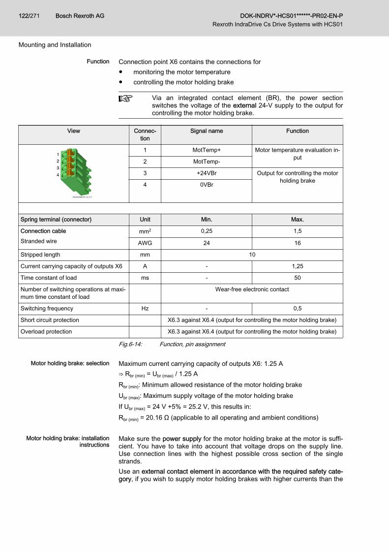
Function Connection point X6 contains the connections for● monitoring the motor temperature● controlling the motor holding brake
Via an integrated contact element (BR), the power sectionswitches the voltage of the external 24-V supply to the output forcontrolling the motor holding brake.
View Connec‐tion
Signal name Function
1 MotTemp+ Motor temperature evaluation in‐put2 MotTemp-
3 +24VBr Output for controlling the motorholding brake4 0VBr
Spring terminal (connector) Unit Min. Max.
Connection cableStranded wire
mm2 0,25 1,5
AWG 24 16
Stripped length mm 10
Current carrying capacity of outputs X6 A - 1,25
Time constant of load ms - 50
Number of switching operations at maxi‐mum time constant of load
Wear-free electronic contact
Switching frequency Hz - 0,5
Short circuit protection X6.3 against X6.4 (output for controlling the motor holding brake)
Overload protection X6.3 against X6.4 (output for controlling the motor holding brake)
Fig.6-14: Function, pin assignment
Motor holding brake: selection Maximum current carrying capacity of outputs X6: 1.25 A⇒ Rbr (min) = Ubr (max) / 1.25 ARbr (min): Minimum allowed resistance of the motor holding brakeUbr (max): Maximum supply voltage of the motor holding brakeIf Ubr (max) = 24 V +5% = 25.2 V, this results in:Rbr (min) = 20.16 Ω (applicable to all operating and ambient conditions)
Motor holding brake: installationinstructions
Make sure the power supply for the motor holding brake at the motor is suffi‐cient. You have to take into account that voltage drops on the supply line.Use connection lines with the highest possible cross section of the singlestrands.Use an external contact element in accordance with the required safety cate‐gory, if you wish to supply motor holding brakes with higher currents than the
Bosch Rexroth AG DOK-INDRV*-HCS01******-PR02-EN-P Rexroth IndraDrive Cs Drive Systems with HCS01
122/271
Mounting and Installation
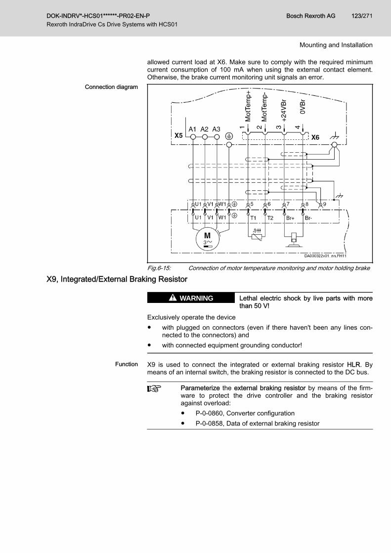
allowed current load at X6. Make sure to comply with the required minimumcurrent consumption of 100 mA when using the external contact element.Otherwise, the brake current monitoring unit signals an error.
Connection diagram
Fig.6-15: Connection of motor temperature monitoring and motor holding brake
X9, Integrated/External Braking Resistor
Lethal electric shock by live parts with morethan 50 V!
WARNING
Exclusively operate the device● with plugged on connectors (even if there haven't been any lines con‐
nected to the connectors) and● with connected equipment grounding conductor!
Function X9 is used to connect the integrated or external braking resistor HLR. Bymeans of an internal switch, the braking resistor is connected to the DC bus.
Parameterize the external braking resistor by means of the firm‐ware to protect the drive controller and the braking resistoragainst overload:● P-0-0860, Converter configuration● P-0-0858, Data of external braking resistor
DOK-INDRV*-HCS01******-PR02-EN-P Rexroth IndraDrive Cs Drive Systems with HCS01
Bosch Rexroth AG 123/271
Mounting and Installation
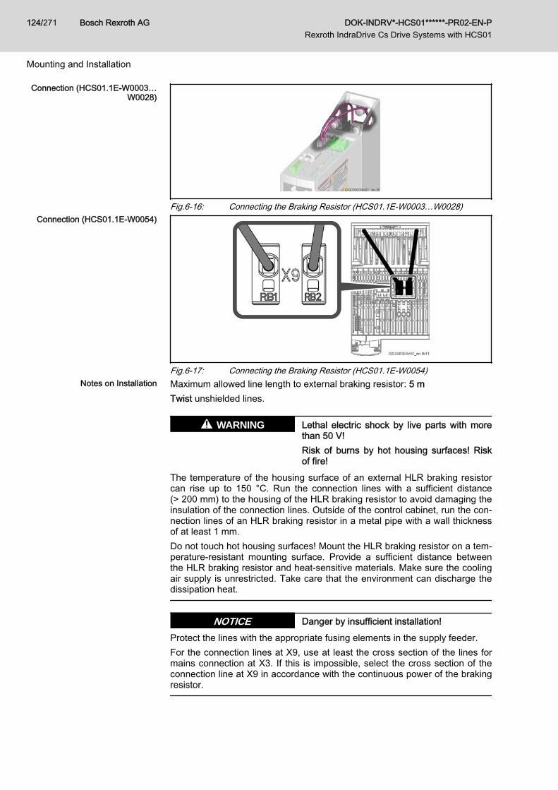
Connection (HCS01.1E-W0003…W0028)
Fig.6-16: Connecting the Braking Resistor (HCS01.1E-W0003…W0028)Connection (HCS01.1E-W0054)
Fig.6-17: Connecting the Braking Resistor (HCS01.1E-W0054)Notes on Installation Maximum allowed line length to external braking resistor: 5 m
Twist unshielded lines.
Lethal electric shock by live parts with morethan 50 V!Risk of burns by hot housing surfaces! Riskof fire!
WARNING
The temperature of the housing surface of an external HLR braking resistorcan rise up to 150 °C. Run the connection lines with a sufficient distance(> 200 mm) to the housing of the HLR braking resistor to avoid damaging theinsulation of the connection lines. Outside of the control cabinet, run the con‐nection lines of an HLR braking resistor in a metal pipe with a wall thicknessof at least 1 mm.Do not touch hot housing surfaces! Mount the HLR braking resistor on a tem‐perature-resistant mounting surface. Provide a sufficient distance betweenthe HLR braking resistor and heat-sensitive materials. Make sure the coolingair supply is unrestricted. Take care that the environment can discharge thedissipation heat.
Danger by insufficient installation!NOTICEProtect the lines with the appropriate fusing elements in the supply feeder.For the connection lines at X9, use at least the cross section of the lines formains connection at X3. If this is impossible, select the cross section of theconnection line at X9 in accordance with the continuous power of the brakingresistor.
Bosch Rexroth AG DOK-INDRV*-HCS01******-PR02-EN-P Rexroth IndraDrive Cs Drive Systems with HCS01
124/271
Mounting and Installation
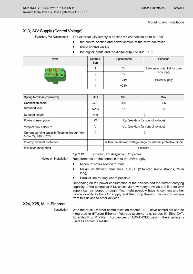
X13, 24V Supply (Control Voltage)Function, Pin Assignment The external 24V supply is applied via connection point X13 for
● the control section and power section of the drive controller● brake control via X6● the digital inputs and the digital output to X31 / X32
View Connec‐tion
Signal name Function
1 0V Reference potential for pow‐er supply2 0V
3 +24V Power supply
4 +24V
Spring terminal (connector) Unit Min. Max.
Connection cableStranded wire
mm2 1,0 2,5
AWG 16 12
Stripped length mm 10
Power consumption W PN3 (see data for control voltage)
Voltage load capacity V UN3 (see data for control voltage)
Current carrying capacity "looping through" from0V to 0V, 24V to 24V
A 10
Polarity reversal protection Within the allowed voltage range by internal protective diode
Insulation monitoring Possible
Fig.6-18: Function, Pin Assignment, PropertiesNotes on Installation Requirements on the connection to the 24V supply:
● Minimum cross section: 1 mm2
● Maximum allowed inductance: 100 µH (2 twisted single strands, 75 mlong)
● Parallel line routing where possibleDepending on the power consumption of the devices and the current carryingcapacity of the connector X13, check via how many devices one line for 24Vsupply can be looped through. You might possibly have to connect anotherdevice directly to the 24V supply and then loop through the control voltagefrom this device to other devices.
X24, X25, Multi-EthernetDescription With the Multi-Ethernet communication module "ET", drive controllers can be
integrated in different Ethernet field bus systems (e.g. sercos III, EtherCAT,EtherNet/IP or ProfiNet). For devices of ADVANCED design, the interface isused as sercos III master.
DOK-INDRV*-HCS01******-PR02-EN-P Rexroth IndraDrive Cs Drive Systems with HCS01
Bosch Rexroth AG 125/271
Mounting and Installation
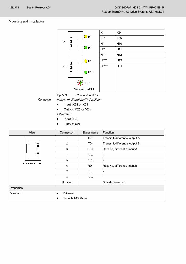
X* X24
X** X25
H* H10
H** H11
H*** H12
H**** H13
H***** H24
Fig.6-19: Connection PointConnection sercos III, EtherNet/IP, ProfiNet:
● Input: X24 or X25● Output: X25 or X24EtherCAT:● Input: X25● Output: X24
View Connection Signal name Function
1 TD+ Transmit, differential output A
2 TD- Transmit, differential output B
3 RD+ Receive, differential input A
4 n. c. -
5 n. c. -
6 RD- Receive, differential input B
7 n. c. -
8 n. c. -
Housing Shield connection
Properties
Standard ● Ethernet● Type: RJ-45, 8-pin
Bosch Rexroth AG DOK-INDRV*-HCS01******-PR02-EN-P Rexroth IndraDrive Cs Drive Systems with HCS01
126/271
Mounting and Installation
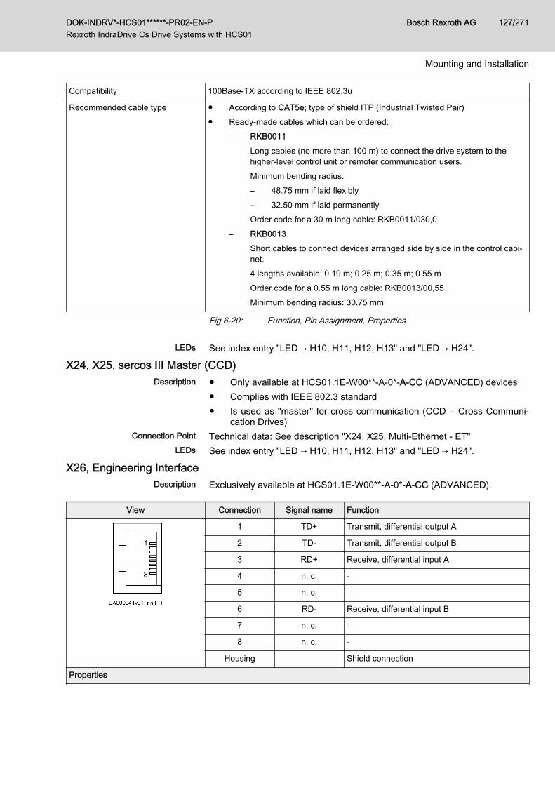
Compatibility 100Base-TX according to IEEE 802.3u
Recommended cable type ● According to CAT5e; type of shield ITP (Industrial Twisted Pair)● Ready-made cables which can be ordered:
– RKB0011Long cables (no more than 100 m) to connect the drive system to thehigher-level control unit or remoter communication users.Minimum bending radius:– 48.75 mm if laid flexibly– 32.50 mm if laid permanentlyOrder code for a 30 m long cable: RKB0011/030,0
– RKB0013Short cables to connect devices arranged side by side in the control cabi‐net.4 lengths available: 0.19 m; 0.25 m; 0.35 m; 0.55 mOrder code for a 0.55 m long cable: RKB0013/00,55Minimum bending radius: 30.75 mm
Fig.6-20: Function, Pin Assignment, Properties
LEDs See index entry "LED → H10, H11, H12, H13" and "LED → H24".
X24, X25, sercos III Master (CCD)Description ● Only available at HCS01.1E-W00**-A-0*-A-CC (ADVANCED) devices
● Complies with IEEE 802.3 standard● Is used as "master" for cross communication (CCD = Cross Communi‐
cation Drives)Connection Point Technical data: See description "X24, X25, Multi-Ethernet - ET"
LEDs See index entry "LED → H10, H11, H12, H13" and "LED → H24".
X26, Engineering InterfaceDescription Exclusively available at HCS01.1E-W00**-A-0*-A-CC (ADVANCED).
View Connection Signal name Function
1 TD+ Transmit, differential output A
2 TD- Transmit, differential output B
3 RD+ Receive, differential input A
4 n. c. -
5 n. c. -
6 RD- Receive, differential input B
7 n. c. -
8 n. c. -
Housing Shield connection
Properties
DOK-INDRV*-HCS01******-PR02-EN-P Rexroth IndraDrive Cs Drive Systems with HCS01
Bosch Rexroth AG 127/271
Mounting and Installation
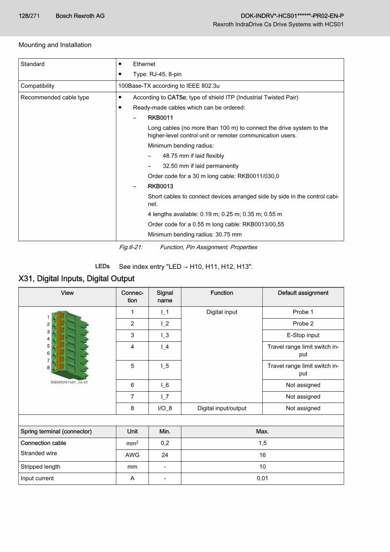
Standard ● Ethernet● Type: RJ-45, 8-pin
Compatibility 100Base-TX according to IEEE 802.3u
Recommended cable type ● According to CAT5e; type of shield ITP (Industrial Twisted Pair)● Ready-made cables which can be ordered:
– RKB0011Long cables (no more than 100 m) to connect the drive system to thehigher-level control unit or remoter communication users.Minimum bending radius:– 48.75 mm if laid flexibly– 32.50 mm if laid permanentlyOrder code for a 30 m long cable: RKB0011/030,0
– RKB0013Short cables to connect devices arranged side by side in the control cabi‐net.4 lengths available: 0.19 m; 0.25 m; 0.35 m; 0.55 mOrder code for a 0.55 m long cable: RKB0013/00,55Minimum bending radius: 30.75 mm
Fig.6-21: Function, Pin Assignment, Properties
LEDs See index entry "LED → H10, H11, H12, H13".
X31, Digital Inputs, Digital OutputView Connec‐
tionSignalname
Function Default assignment
1 I_1 Digital input Probe 1
2 I_2 Probe 2
3 I_3 E-Stop input
4 I_4 Travel range limit switch in‐put
5 I_5 Travel range limit switch in‐put
6 I_6 Not assigned
7 I_7 Not assigned
8 I/O_8 Digital input/output Not assigned
Spring terminal (connector) Unit Min. Max.
Connection cableStranded wire
mm2 0,2 1,5
AWG 24 16
Stripped length mm - 10
Input current A - 0,01
Bosch Rexroth AG DOK-INDRV*-HCS01******-PR02-EN-P Rexroth IndraDrive Cs Drive Systems with HCS01
128/271
Mounting and Installation
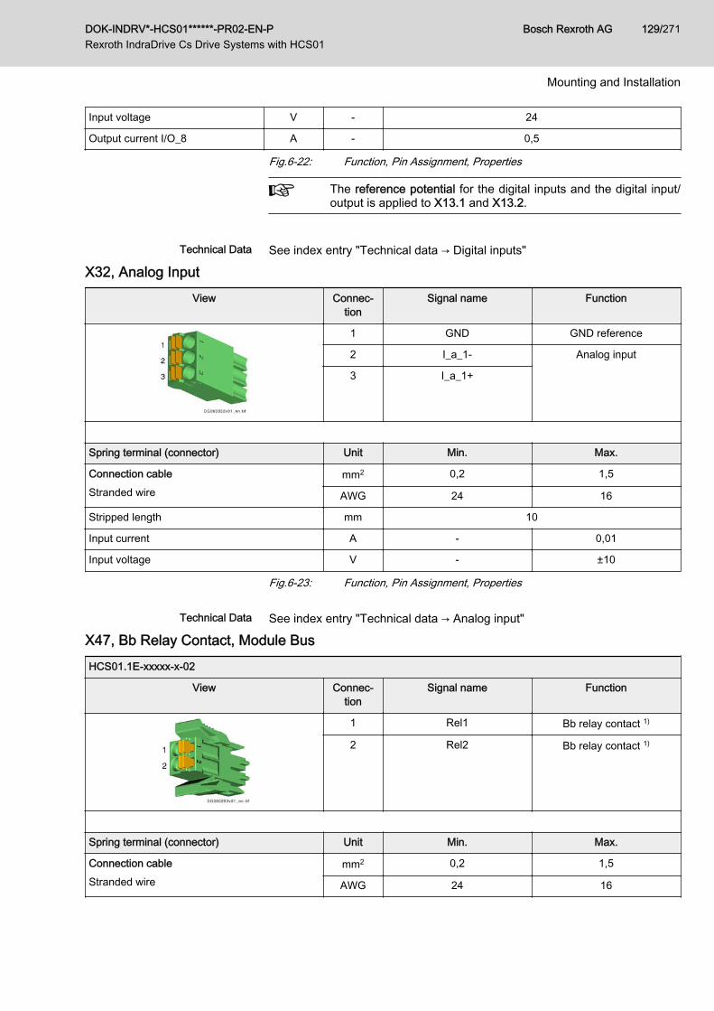
Input voltage V - 24
Output current I/O_8 A - 0,5
Fig.6-22: Function, Pin Assignment, Properties
The reference potential for the digital inputs and the digital input/output is applied to X13.1 and X13.2.
Technical Data See index entry "Technical data → Digital inputs"
X32, Analog InputView Connec‐
tionSignal name Function
1 GND GND reference
2 I_a_1- Analog input
3 I_a_1+
Spring terminal (connector) Unit Min. Max.
Connection cableStranded wire
mm2 0,2 1,5
AWG 24 16
Stripped length mm 10
Input current A - 0,01
Input voltage V - ±10
Fig.6-23: Function, Pin Assignment, Properties
Technical Data See index entry "Technical data → Analog input"
X47, Bb Relay Contact, Module BusHCS01.1E-xxxxx-x-02
View Connec‐tion
Signal name Function
1 Rel1 Bb relay contact 1)
2 Rel2 Bb relay contact 1)
Spring terminal (connector) Unit Min. Max.
Connection cableStranded wire
mm2 0,2 1,5
AWG 24 16
DOK-INDRV*-HCS01******-PR02-EN-P Rexroth IndraDrive Cs Drive Systems with HCS01
Bosch Rexroth AG 129/271
Mounting and Installation
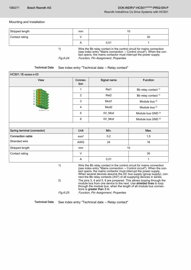
Stripped length mm 10
Contact rating V 30
A 0,01 1
1) Wire the Bb relay contact in the control circuit for mains connection(see index entry "Mains connection → Control circuit"). When the con‐tact opens, the mains contactor must interrupt the power supply.
Fig.6-24: Function, Pin Assignment, Properties
Technical Data See index entry "Technical data → Relay contact"
HCS01.1E-xxxxx-x-03
View Connec‐tion
Signal name Function
1 Rel1 Bb relay contact 1)
2 Rel2 Bb relay contact 1)
3 Mod1 Module bus 2)
4 Mod2 Module bus 2)
5 0V_Mod Module bus GND 2)
6 0V_Mod Module bus GND 2)
Spring terminal (connector) Unit Min. Max.
Connection cableStranded wire
mm2 0,2 1,5
AWG 24 16
Stripped length mm 10
Contact rating V 30
A 0,01 1
1) Wire the Bb relay contact in the control circuit for mains connection(see index entry "Mains connection → Control circuit"). When the con‐tact opens, the mains contactor must interrupt the power supply.When several devices assume the DC bus supply (group supply), con‐nect the Bb relay contacts (X47) of all supplying devices in series.
2) The pins 3, 4 and 5, 6 are jumpered. This allows looping through themodule bus from one device to the next. Use shielded lines to loopthrough the module bus, when the length of all module bus connec‐tions is greater than 3 m.
Fig.6-25: Function, Pin Assignment, Properties
Technical Data See index entry "Technical data → Relay contact"
Bosch Rexroth AG DOK-INDRV*-HCS01******-PR02-EN-P Rexroth IndraDrive Cs Drive Systems with HCS01
130/271
Mounting and Installation
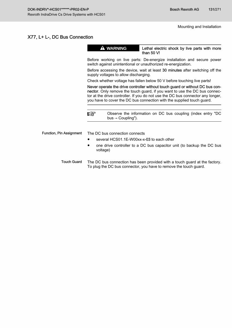
X77, L+ L-, DC Bus Connection
Lethal electric shock by live parts with morethan 50 V!
WARNING
Before working on live parts: De-energize installation and secure powerswitch against unintentional or unauthorized re-energization.Before accessing the device, wait at least 30 minutes after switching off thesupply voltages to allow discharging.Check whether voltage has fallen below 50 V before touching live parts!Never operate the drive controller without touch guard or without DC bus con‐nector. Only remove the touch guard, if you want to use the DC bus connec‐tor at the drive controller. If you do not use the DC bus connector any longer,you have to cover the DC bus connection with the supplied touch guard.
Observe the information on DC bus coupling (index entry "DCbus → Coupling").
Function, Pin Assignment The DC bus connection connects
● several HCS01.1E-W00xx-x-03 to each other● one drive controller to a DC bus capacitor unit (to backup the DC bus
voltage)
Touch Guard The DC bus connection has been provided with a touch guard at the factory.To plug the DC bus connector, you have to remove the touch guard.
DOK-INDRV*-HCS01******-PR02-EN-P Rexroth IndraDrive Cs Drive Systems with HCS01
Bosch Rexroth AG 131/271
Mounting and Installation
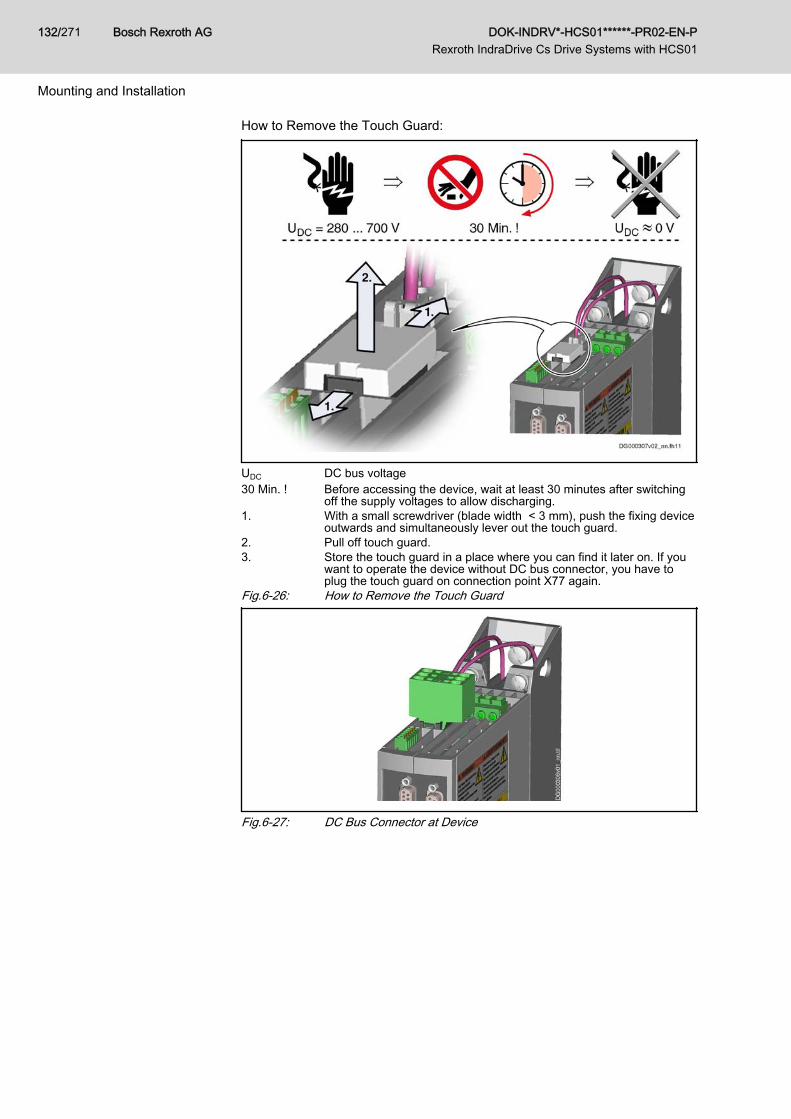
How to Remove the Touch Guard:
UDC DC bus voltage30 Min. ! Before accessing the device, wait at least 30 minutes after switching
off the supply voltages to allow discharging.1. With a small screwdriver (blade width < 3 mm), push the fixing device
outwards and simultaneously lever out the touch guard.2. Pull off touch guard.3. Store the touch guard in a place where you can find it later on. If you
want to operate the device without DC bus connector, you have toplug the touch guard on connection point X77 again.
Fig.6-26: How to Remove the Touch Guard
Fig.6-27: DC Bus Connector at Device
Bosch Rexroth AG DOK-INDRV*-HCS01******-PR02-EN-P Rexroth IndraDrive Cs Drive Systems with HCS01
132/271
Mounting and Installation
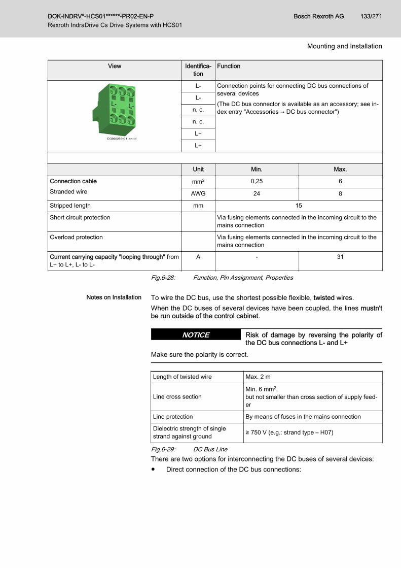
View Identifica‐tion
Function
L- Connection points for connecting DC bus connections ofseveral devices(The DC bus connector is available as an accessory; see in‐dex entry "Accessories → DC bus connector")
L-
n. c.
n. c.
L+
L+
Unit Min. Max.
Connection cableStranded wire
mm2 0,25 6
AWG 24 8
Stripped length mm 15
Short circuit protection Via fusing elements connected in the incoming circuit to themains connection
Overload protection Via fusing elements connected in the incoming circuit to themains connection
Current carrying capacity "looping through" fromL+ to L+, L‑ to L‑
A - 31
Fig.6-28: Function, Pin Assignment, Properties
Notes on Installation To wire the DC bus, use the shortest possible flexible, twisted wires.When the DC buses of several devices have been coupled, the lines mustn'tbe run outside of the control cabinet.
Risk of damage by reversing the polarity ofthe DC bus connections L- and L+
NOTICE
Make sure the polarity is correct.
Length of twisted wire Max. 2 m
Line cross sectionMin. 6 mm2, but not smaller than cross section of supply feed‐er
Line protection By means of fuses in the mains connection
Dielectric strength of singlestrand against ground ≥ 750 V (e.g.: strand type – H07)
Fig.6-29: DC Bus LineThere are two options for interconnecting the DC buses of several devices:● Direct connection of the DC bus connections:
DOK-INDRV*-HCS01******-PR02-EN-P Rexroth IndraDrive Cs Drive Systems with HCS01
Bosch Rexroth AG 133/271
Mounting and Installation
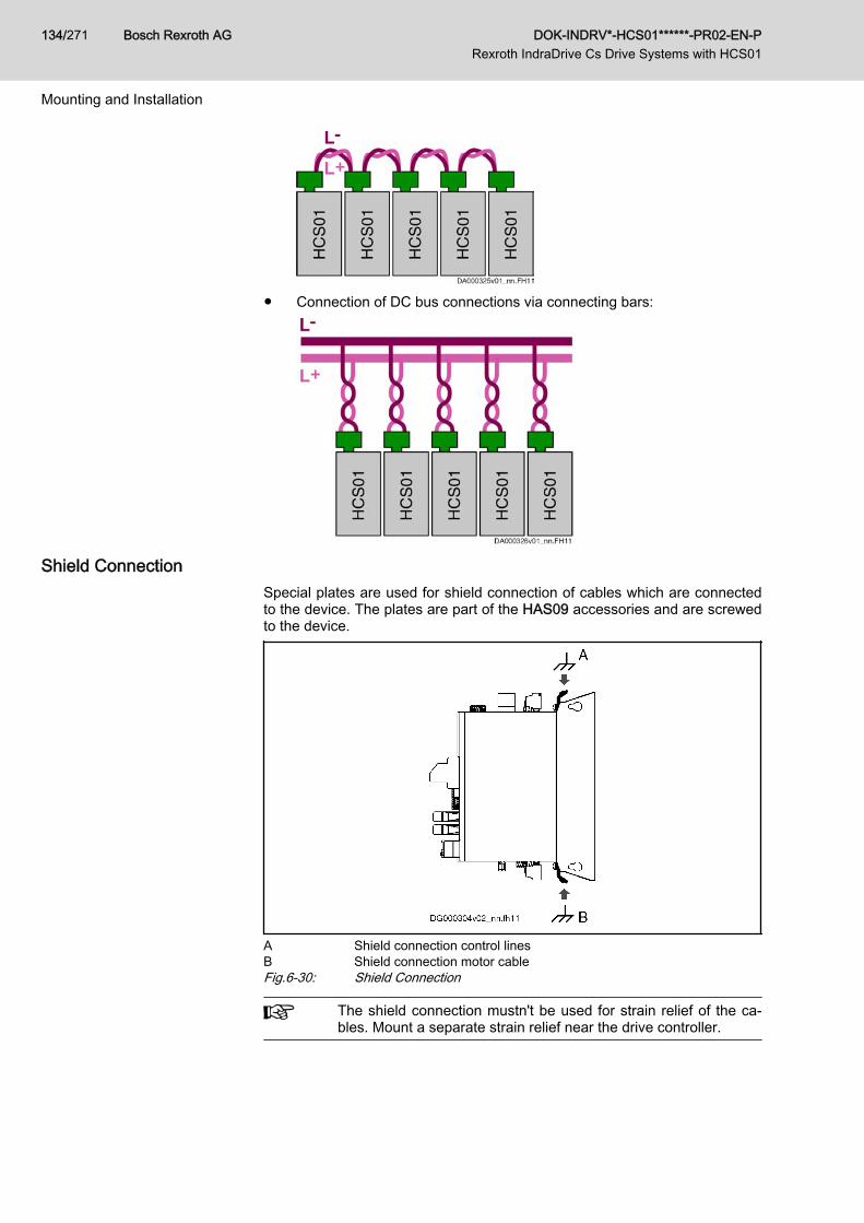
● Connection of DC bus connections via connecting bars:
Shield ConnectionSpecial plates are used for shield connection of cables which are connectedto the device. The plates are part of the HAS09 accessories and are screwedto the device.
A Shield connection control linesB Shield connection motor cableFig.6-30: Shield Connection
The shield connection mustn't be used for strain relief of the ca‐bles. Mount a separate strain relief near the drive controller.
Bosch Rexroth AG DOK-INDRV*-HCS01******-PR02-EN-P Rexroth IndraDrive Cs Drive Systems with HCS01
134/271
Mounting and Installation
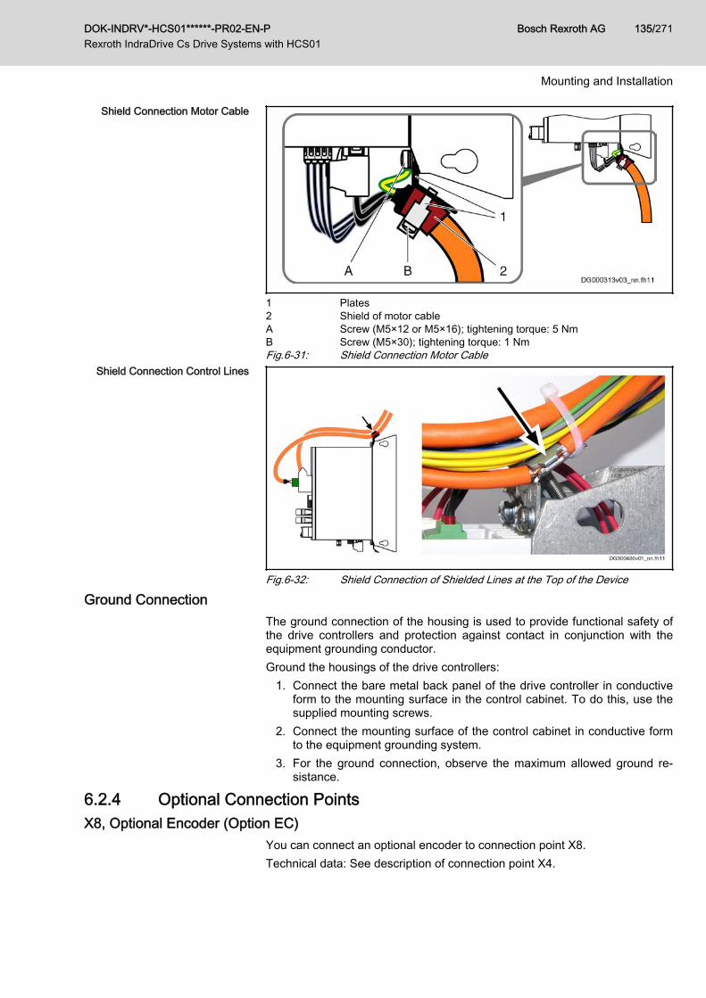
Shield Connection Motor Cable
1 Plates2 Shield of motor cableA Screw (M5×12 or M5×16); tightening torque: 5 NmB Screw (M5×30); tightening torque: 1 NmFig.6-31: Shield Connection Motor Cable
Shield Connection Control Lines
Fig.6-32: Shield Connection of Shielded Lines at the Top of the Device
Ground ConnectionThe ground connection of the housing is used to provide functional safety ofthe drive controllers and protection against contact in conjunction with theequipment grounding conductor.Ground the housings of the drive controllers:
1. Connect the bare metal back panel of the drive controller in conductiveform to the mounting surface in the control cabinet. To do this, use thesupplied mounting screws.
2. Connect the mounting surface of the control cabinet in conductive formto the equipment grounding system.
3. For the ground connection, observe the maximum allowed ground re‐sistance.
6.2.4 Optional Connection PointsX8, Optional Encoder (Option EC)
You can connect an optional encoder to connection point X8.Technical data: See description of connection point X4.
DOK-INDRV*-HCS01******-PR02-EN-P Rexroth IndraDrive Cs Drive Systems with HCS01
Bosch Rexroth AG 135/271
Mounting and Installation
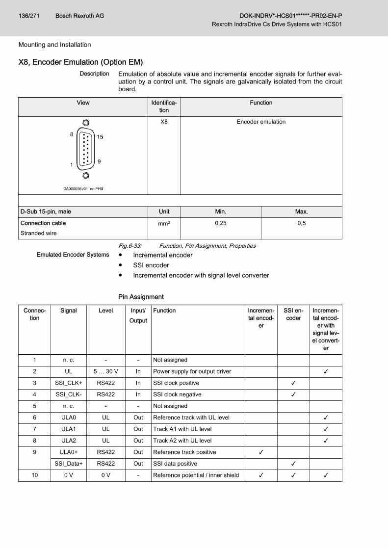
X8, Encoder Emulation (Option EM)Description Emulation of absolute value and incremental encoder signals for further eval‐
uation by a control unit. The signals are galvanically isolated from the circuitboard.
View Identifica‐tion
Function
X8 Encoder emulation
D-Sub 15-pin, male Unit Min. Max.
Connection cableStranded wire
mm2 0,25 0,5
Fig.6-33: Function, Pin Assignment, PropertiesEmulated Encoder Systems ● Incremental encoder
● SSI encoder● Incremental encoder with signal level converter Pin Assignment
Connec‐tion
Signal Level Input/Output
Function Incremen‐tal encod‐
er
SSI en‐coder
Incremen‐tal encod‐
er withsignal lev‐el convert‐
er
1 n. c. - - Not assigned
2 UL 5 … 30 V In Power supply for output driver ✓
3 SSI_CLK+ RS422 In SSI clock positive ✓
4 SSI_CLK- RS422 In SSI clock negative ✓
5 n. c. - - Not assigned
6 ULA0 UL Out Reference track with UL level ✓
7 ULA1 UL Out Track A1 with UL level ✓
8 ULA2 UL Out Track A2 with UL level ✓
9 ULA0+ RS422 Out Reference track positive ✓
SSI_Data+ RS422 Out SSI data positive ✓
10 0 V 0 V - Reference potential / inner shield ✓ ✓ ✓
Bosch Rexroth AG DOK-INDRV*-HCS01******-PR02-EN-P Rexroth IndraDrive Cs Drive Systems with HCS01
136/271
Mounting and Installation
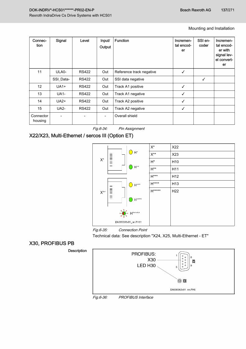
Connec‐tion
Signal Level Input/Output
Function Incremen‐tal encod‐
er
SSI en‐coder
Incremen‐tal encod‐
er withsignal lev‐el convert‐
er
11 ULA0- RS422 Out Reference track negative ✓
SSI_Data- RS422 Out SSI data negative ✓
12 UA1+ RS422 Out Track A1 positive ✓
13 UA1- RS422 Out Track A1 negative ✓
14 UA2+ RS422 Out Track A2 positive ✓
15 UA2- RS422 Out Track A2 negative ✓
Connectorhousing
- - - Overall shield
Fig.6-34: Pin Assignment
X22/X23, Multi-Ethernet / sercos III (Option ET)
X* X22
X** X23
H* H10
H** H11
H*** H12
H**** H13
H***** H22
Fig.6-35: Connection PointTechnical data: See description "X24, X25, Multi-Ethernet - ET"
X30, PROFIBUS PBDescription
Fig.6-36: PROFIBUS Interface
DOK-INDRV*-HCS01******-PR02-EN-P Rexroth IndraDrive Cs Drive Systems with HCS01
Bosch Rexroth AG 137/271
Mounting and Installation
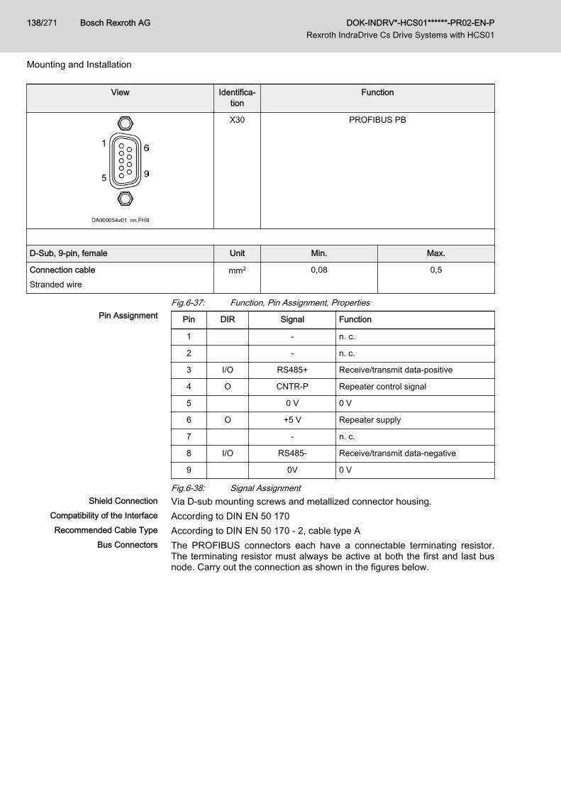
View Identifica‐tion
Function
X30 PROFIBUS PB
D-Sub, 9-pin, female Unit Min. Max.
Connection cableStranded wire
mm2 0,08 0,5
Fig.6-37: Function, Pin Assignment, PropertiesPin Assignment Pin DIR Signal Function
1 - n. c.
2 - n. c.
3 I/O RS485+ Receive/transmit data-positive
4 O CNTR-P Repeater control signal
5 0 V 0 V
6 O +5 V Repeater supply
7 - n. c.
8 I/O RS485- Receive/transmit data-negative
9 0V 0 V
Fig.6-38: Signal AssignmentShield Connection Via D-sub mounting screws and metallized connector housing.
Compatibility of the Interface According to DIN EN 50 170Recommended Cable Type According to DIN EN 50 170 - 2, cable type A
Bus Connectors The PROFIBUS connectors each have a connectable terminating resistor.The terminating resistor must always be active at both the first and last busnode. Carry out the connection as shown in the figures below.
Bosch Rexroth AG DOK-INDRV*-HCS01******-PR02-EN-P Rexroth IndraDrive Cs Drive Systems with HCS01
138/271
Mounting and Installation
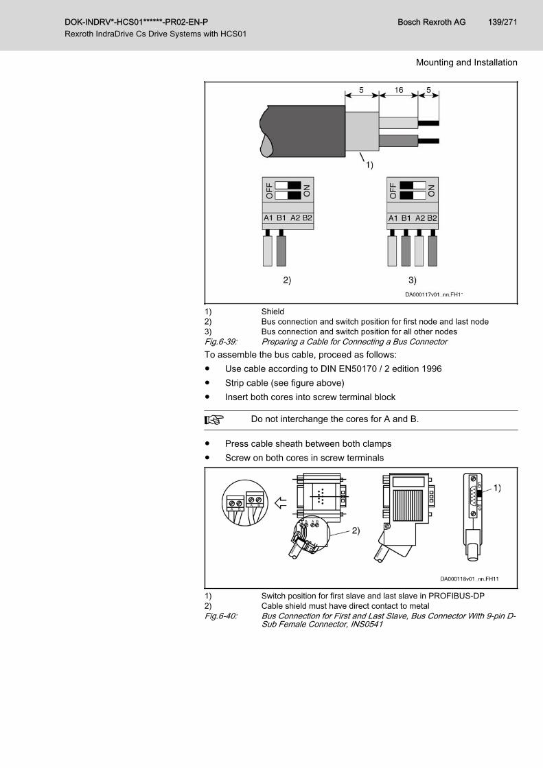
1) Shield2) Bus connection and switch position for first node and last node3) Bus connection and switch position for all other nodesFig.6-39: Preparing a Cable for Connecting a Bus ConnectorTo assemble the bus cable, proceed as follows:● Use cable according to DIN EN50170 / 2 edition 1996● Strip cable (see figure above)● Insert both cores into screw terminal block
Do not interchange the cores for A and B.
● Press cable sheath between both clamps● Screw on both cores in screw terminals
1) Switch position for first slave and last slave in PROFIBUS-DP2) Cable shield must have direct contact to metalFig.6-40: Bus Connection for First and Last Slave, Bus Connector With 9-pin D-
Sub Female Connector, INS0541
DOK-INDRV*-HCS01******-PR02-EN-P Rexroth IndraDrive Cs Drive Systems with HCS01
Bosch Rexroth AG 139/271
Mounting and Installation
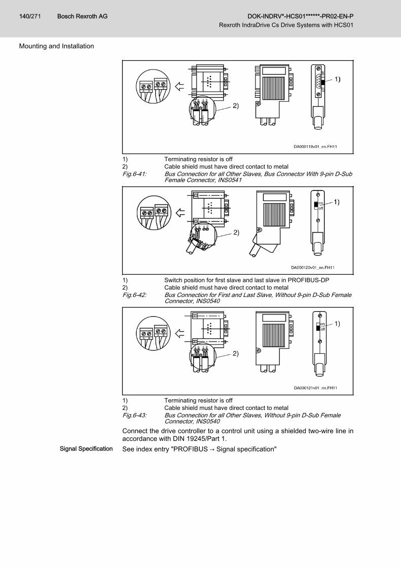
1) Terminating resistor is off2) Cable shield must have direct contact to metalFig.6-41: Bus Connection for all Other Slaves, Bus Connector With 9-pin D-Sub
Female Connector, INS0541
1) Switch position for first slave and last slave in PROFIBUS-DP2) Cable shield must have direct contact to metalFig.6-42: Bus Connection for First and Last Slave, Without 9-pin D-Sub Female
Connector, INS0540
1) Terminating resistor is off2) Cable shield must have direct contact to metalFig.6-43: Bus Connection for all Other Slaves, Without 9-pin D-Sub Female
Connector, INS0540Connect the drive controller to a control unit using a shielded two-wire line inaccordance with DIN 19245/Part 1.
Signal Specification See index entry "PROFIBUS → Signal specification"
Bosch Rexroth AG DOK-INDRV*-HCS01******-PR02-EN-P Rexroth IndraDrive Cs Drive Systems with HCS01
140/271
Mounting and Installation
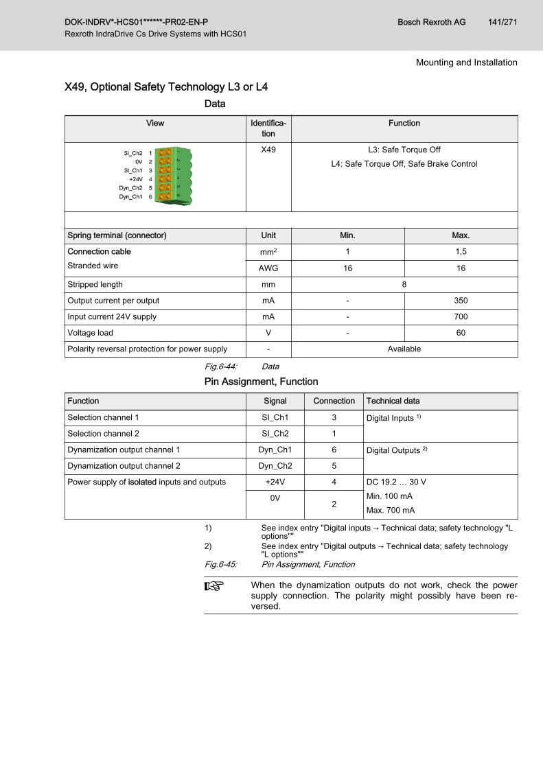
X49, Optional Safety Technology L3 or L4Data
View Identifica‐tion
Function
X49 L3: Safe Torque OffL4: Safe Torque Off, Safe Brake Control
Spring terminal (connector) Unit Min. Max.
Connection cableStranded wire
mm2 1 1,5
AWG 16 16
Stripped length mm 8
Output current per output mA - 350
Input current 24V supply mA - 700
Voltage load V - 60
Polarity reversal protection for power supply - Available
Fig.6-44: Data
Pin Assignment, Function
Function Signal Connection Technical data
Selection channel 1 SI_Ch1 3 Digital Inputs 1)
Selection channel 2 SI_Ch2 1
Dynamization output channel 1 Dyn_Ch1 6 Digital Outputs 2)
Dynamization output channel 2 Dyn_Ch2 5
Power supply of isolated inputs and outputs +24V 4 DC 19.2 … 30 VMin. 100 mAMax. 700 mA
0V2
1) See index entry "Digital inputs → Technical data; safety technology "Loptions""
2) See index entry "Digital outputs → Technical data; safety technology"L options""
Fig.6-45: Pin Assignment, Function
When the dynamization outputs do not work, check the powersupply connection. The polarity might possibly have been re‐versed.
DOK-INDRV*-HCS01******-PR02-EN-P Rexroth IndraDrive Cs Drive Systems with HCS01
Bosch Rexroth AG 141/271
Mounting and Installation
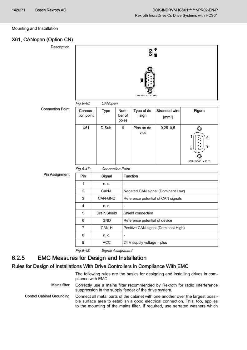
X61, CANopen (Option CN)Description
Fig.6-46: CANopenConnection Point Connec‐
tion pointType Num‐
ber ofpoles
Type of de‐sign
Stranded wire[mm²]
Figure
X61 D‑Sub 9 Pins on de‐vice
0,25–0,5
Fig.6-47: Connection PointPin Assignment Pin Signal Function
1 n. c. -
2 CAN-L Negated CAN signal (Dominant Low)
3 CAN-GND Reference potential of CAN signals
4 n. c. -
5 Drain/Shield Shield connection
6 GND Reference potential of device
7 CAN-H Positive CAN signal (Dominant High)
8 n. c. -
9 VCC 24 V supply voltage – plus
Fig.6-48: Signal Assignment
6.2.5 EMC Measures for Design and InstallationRules for Design of Installations With Drive Controllers in Compliance With EMC
The following rules are the basics for designing and installing drives in com‐pliance with EMC.
Mains filter Correctly use a mains filter recommended by Rexroth for radio interferencesuppression in the supply feeder of the drive system.
Control Cabinet Grounding Connect all metal parts of the cabinet with one another over the largest possi‐ble surface area to establish a good electrical connection. This, too, appliesto the mounting of the mains filter. If required, use serrated washers which
Bosch Rexroth AG DOK-INDRV*-HCS01******-PR02-EN-P Rexroth IndraDrive Cs Drive Systems with HCS01
142/271
Mounting and Installation

cut through the paint surface. Connect the cabinet door to the control cabinetusing the shortest possible grounding straps.
Line Routing Avoid coupling routes between lines with high potential of noise and noise-free lines; therefore, signal, mains and motor lines and power cables have tobe routed separately from another. Minimum distance: 10 cm. Provide sepa‐rating sheets between power and signal lines. Ground separating sheets sev‐eral times.The lines with high potential of noise include:● Lines at the mains connection (incl. synchronization connection)● Lines at the motor connection● Lines at the DC bus connectionGenerally, interference injections are reduced by routing cables close togrounded sheet steel plates. For this reason, cables and wires should not berouted freely in the cabinet, but close to the cabinet housing or mounting pan‐els. Separate the incoming and outgoing cables of the radio interference sup‐pression filter.
Interference Suppression Ele‐ments
Provide the following components in the control cabinet with interference sup‐pression combinations:● Contactors● Relays● Solenoid valves● Electromechanical operating hours countersConnect these combinations directly at each coil.
Twisted Wires Twist unshielded wires belonging to the same circuit (feeder and return ca‐ble) or keep the surface between feeder and return cable as small as possi‐ble. Wires that are not used have to be grounded at both ends.
Lines of Measuring Systems Lines of measuring systems must be shielded. Connect the shield to groundat both ends and over the largest possible surface area. The shield may notbe interrupted, e.g. using intermediate terminals.
Digital Signal Lines Ground the shields of digital signal lines at both ends (transmitter and receiv‐er) over the largest possible surface area and with low impedance. In thecase of bad ground connection between transmitter and receiver, additionallyroute a bonding conductor (min. 10 mm2). Braided shields are better than foilshields.
Analog Signal Lines Ground the shields of analog signal lines at one end (transmitter or receiver)over the largest possible surface area and with low impedance. This avoidslow-frequency interference current (in the mains frequency range) on theshield.
Connecting the Mains Choke Keep connection lines of the mains choke at the drive controller as short aspossible and twist them.
Installing the Motor Power Cable ● Use shielded motor power cables or run motor power cables in a shiel‐ded duct
● Use the shortest possible motor power cables● Ground shield of motor power cable at both ends over the largest possi‐
ble surface area to establish a good electrical connection● Run motor lines in shielded form inside the control cabinet● Do not use any steel-shielded lines● The shield of the motor power cable mustn't be interrupted by mounted
components, such as output chokes, sine filters or motor filters
DOK-INDRV*-HCS01******-PR02-EN-P Rexroth IndraDrive Cs Drive Systems with HCS01
Bosch Rexroth AG 143/271
Mounting and Installation
EMC-Optimal Installation in Facility and Control CabinetGeneral InformationFor EMC-optimal installation, a spatial separation of the interference-freearea (mains connection) and the interference-susceptible area (drive compo‐nents) is recommended, as shown in the figures below.
Recommendation: For EMC-optimal installation in the control cab‐inet, use a separate control cabinet panel for the drive compo‐nents.
Division Into Areas (Zones)Exemplary arrangements in the control cabinet: See section Control CabinetDesign According to Interference Areas - Exemplary Arrangements,page 145.We distinguish three areas:
1. Interference-free area of control cabinet (area A):This includes:● Supply feeder, input terminals, fuse, main switch, mains side of
mains filter for drives and corresponding connecting lines● Control voltage or auxiliary voltage connection with power supply
unit, fuse and other parts unless connection is run via the mains fil‐ter of the AC drives
● All components that are not electrically connected with the drivesystem
2. Interference-susceptible area (area B):● Mains connections between drive system and mains filter for
drives, mains contactor● Interface lines of drive controller
3. Strongly interference-susceptible area (area C):● Motor power cables including single cores
Never run lines of one of these areas in parallel with lines of another area sothat there isn't any unwanted interference injection from one area to the otherand that the filter is jumpered with regard to high frequency. Use the shortestpossible connecting lines.Recommendation for complex systems: Install drive components in one cabi‐net and the control units in a second, separate cabinet.Badly grounded control cabinet doors act as antennas. Therefore, connectthe control cabinet doors to the cabinet on top, in the middle and on the bot‐tom via short equipment grounding conductors with a cross section of at least6 mm2 or, even better, via grounding straps with the same cross section.Make sure connection points have good contact.
Bosch Rexroth AG DOK-INDRV*-HCS01******-PR02-EN-P Rexroth IndraDrive Cs Drive Systems with HCS01
144/271
Mounting and Installation
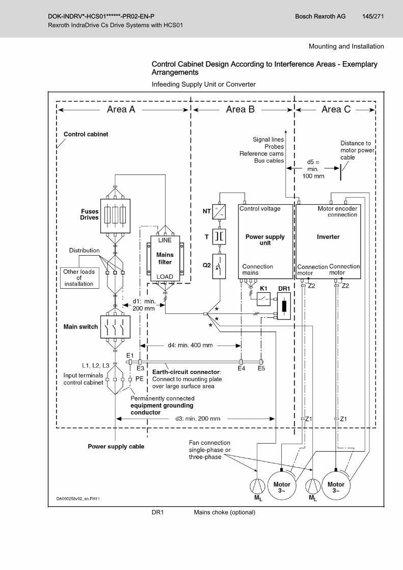
Control Cabinet Design According to Interference Areas - ExemplaryArrangementsInfeeding Supply Unit or Converter
DR1 Mains choke (optional)
DOK-INDRV*-HCS01******-PR02-EN-P Rexroth IndraDrive Cs Drive Systems with HCS01
Bosch Rexroth AG 145/271
Mounting and Installation
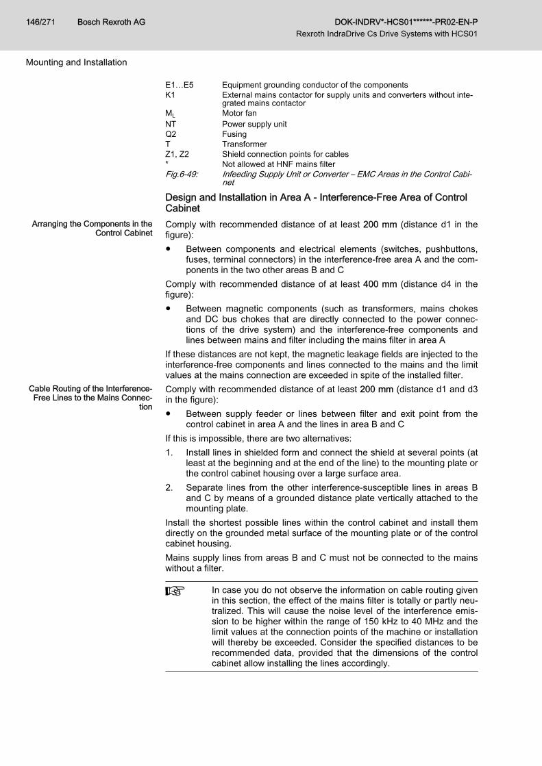
E1…E5 Equipment grounding conductor of the componentsK1 External mains contactor for supply units and converters without inte‐
grated mains contactorML Motor fanNT Power supply unitQ2 FusingT TransformerZ1, Z2 Shield connection points for cables* Not allowed at HNF mains filterFig.6-49: Infeeding Supply Unit or Converter – EMC Areas in the Control Cabi‐
net
Design and Installation in Area A - Interference-Free Area of ControlCabinet
Arranging the Components in theControl Cabinet
Comply with recommended distance of at least 200 mm (distance d1 in thefigure):● Between components and electrical elements (switches, pushbuttons,
fuses, terminal connectors) in the interference-free area A and the com‐ponents in the two other areas B and C
Comply with recommended distance of at least 400 mm (distance d4 in thefigure):● Between magnetic components (such as transformers, mains chokes
and DC bus chokes that are directly connected to the power connec‐tions of the drive system) and the interference-free components andlines between mains and filter including the mains filter in area A
If these distances are not kept, the magnetic leakage fields are injected to theinterference-free components and lines connected to the mains and the limitvalues at the mains connection are exceeded in spite of the installed filter.
Cable Routing of the Interference-Free Lines to the Mains Connec‐
tion
Comply with recommended distance of at least 200 mm (distance d1 and d3in the figure):● Between supply feeder or lines between filter and exit point from the
control cabinet in area A and the lines in area B and CIf this is impossible, there are two alternatives:1. Install lines in shielded form and connect the shield at several points (at
least at the beginning and at the end of the line) to the mounting plate orthe control cabinet housing over a large surface area.
2. Separate lines from the other interference-susceptible lines in areas Band C by means of a grounded distance plate vertically attached to themounting plate.
Install the shortest possible lines within the control cabinet and install themdirectly on the grounded metal surface of the mounting plate or of the controlcabinet housing.Mains supply lines from areas B and C must not be connected to the mainswithout a filter.
In case you do not observe the information on cable routing givenin this section, the effect of the mains filter is totally or partly neu‐tralized. This will cause the noise level of the interference emis‐sion to be higher within the range of 150 kHz to 40 MHz and thelimit values at the connection points of the machine or installationwill thereby be exceeded. Consider the specified distances to berecommended data, provided that the dimensions of the controlcabinet allow installing the lines accordingly.
Bosch Rexroth AG DOK-INDRV*-HCS01******-PR02-EN-P Rexroth IndraDrive Cs Drive Systems with HCS01
146/271
Mounting and Installation

Routing and Connecting a NeutralConductor (N)
If a neutral conductor is used together with a three-phase connection, it mustnot be installed unfiltered in zones B and C, in order to keep interference offthe mains.
Motor Fan at Mains Filter Single-phase or three-phase supply lines of motor fans, that are usually rout‐ed in parallel with motor power cables or interference-susceptible lines, mustbe filtered:● In drive systems with regenerative supply units, via a separate single-
phase (NFE type) or three-phase filter (HNF type) near the mains con‐nection of the control cabinet
● In drive systems with only infeeding supply units, via the available three-phase filter of the drive system
When switching power off, make sure the fan is not switched off.When switching power off, make sure the fan is not switched off.
Loads at Mains Filter of Drive Sys‐tem Only operate allowed loads at the mains filter of the drive system!
At the three-phase filter for the power connection of regenerativesupply units, it is only allowed to operate the following loads:● HMV supply unit with mains choke and, if necessary, mains
contactorDo not operate any motor fans, power supply units etc. at themains filter of the drive system.
Shielding Mains Supply Lines inControl Cabinet
If there is a high degree of interference injection to the mains supply line with‐in the control cabinet, although you have observed the above instructions (tobe found out by EMC measurement according to standard), proceed as fol‐lows:● Only use shielded lines in area A● Connect shields to the mounting plate at the beginning and the end of
the line by means of clipsThe same procedure may be required for long cables of more than 2 m be‐tween the point of power supply connection of the control cabinet and the fil‐ter within the control cabinet.
Mains Filters for AC Drives Ideally mount the mains filter on the parting line between the areas A and B.Make sure the ground connection between filter housing and housing of thedrive controllers has good electrically conductive properties.If single-phase loads are connected on the load side of the filter, their currentmay be a maximum of 10% of the three-phase operating current. A highly im‐balanced load of the filter would deteriorate its interference suppression ca‐pacity.If the mains voltage is more than 480 V, connect the filter to the output side ofthe transformer and not to the supply side of the transformer.
Grounding In the case of bad ground connections in the installation, the distance be‐tween the lines to the grounding points E1, E2 in area A and the othergrounding points of the drive system should be at least d4 = 400 mm, in orderto minimize interference injection from ground and ground cables to the pow‐er input lines.See also Division Into Areas (Zones), page 144.
Point of Connection for EquipmentGrounding Conductor at Machine,
Installation, Control Cabinet
The equipment grounding conductor of the power cable of the machine, in‐stallation or control cabinet has to be permanently connected at point PE andhave a cross section of at least 10 mm2 or to be complemented by a secondequipment grounding conductor via separate terminal connectors (accordingto EN 61800-5-1:2007, section 4.3.5.5.2). If the cross section of the outer
DOK-INDRV*-HCS01******-PR02-EN-P Rexroth IndraDrive Cs Drive Systems with HCS01
Bosch Rexroth AG 147/271
Mounting and Installation

conductor is bigger, the cross section of the equipment grounding conductormust be accordingly bigger.
Design and Installation in Area B - Interference-Susceptible Area ofControl Cabinet
Arranging Components and Lines Modules, components and lines in area B should be placed at a distance ofat least d1 = 200 mm from modules and lines in area A.Alternative: Shield modules, components and lines in area B by distanceplates mounted vertically on the mounting plate from modules and lines inarea A or use shielded lines.Only connect power supply units for auxiliary or control voltage connectionsin the drive system to the mains via a mains filter. See Division Into Areas(Zones), page 144.Install the shortest possible lines between drive controller and filter.
Control Voltage or Auxiliary Volt‐age Connection
Only in exceptional cases should you connect power supply unit and fusingfor the control voltage connection to phase and neutral conductor. In thiscase, mount and install these components in area A far away from the areasB and C of the drive system. For details see section Design and Installation inArea A - Interference-Free Area of Control Cabinet, page 146.Run the connection between control voltage connection of the drive systemand power supply unit used through area B over the shortest distance.
Line Routing Run the lines along grounded metal surfaces, in order to minimize radiationof interference fields to area A (transmitting antenna effect).
Design and Installation in Area C - Strongly Interference-SusceptibleArea of Control CabinetArea C mainly concerns the motor power cables, especially at the connectionpoint at the drive controller.
Influence of the Motor Power Ca‐ble
The longer the motor power cable, the greater its leakage capacitance. Tocomply with a certain EMC limit value, the allowed leakage capacitance ofthe mains filter is limited. For the calculation of the leakage capacitance, seethe documentation on the drive system of the drive controller used.
● Run the shortest possible motor power cables.● Only use shielded motor power cables by Rexroth.
Routing the Motor Power Cablesand Motor Encoder Cables
Route the motor power cables and motor encoder cables along groundedmetal surfaces, both inside the control cabinet and outside of it, in order tominimize radiation of interference fields. If possible, route the motor powercables and motor encoder cables in metal-grounded cable ducts.Route the motor power cables and motor encoder cables● with a distance of at least d5 = 100 mm to interference-free lines, as
well as to signal cables and signal lines(alternatively separated by a grounded distance plate)
● in separate cable ducts, if possibleRouting the Motor Power Cables
and Mains Connection LinesFor converters (drive controllers with individual mains connection), route mo‐tor power cables and (unfiltered) mains connection lines in parallel for a maxi‐mum distance of 300 mm. After that distance, route motor power cables andpower supply cables in opposite directions and preferably in separate cableducts.
Bosch Rexroth AG DOK-INDRV*-HCS01******-PR02-EN-P Rexroth IndraDrive Cs Drive Systems with HCS01
148/271
Mounting and Installation
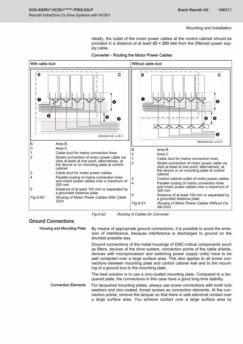
Ideally, the outlet of the motor power cables at the control cabinet should beprovided in a distance of at least d3 = 200 mm from the (filtered) power sup‐ply cable.Converter - Routing the Motor Power Cables
With cable duct Without cable duct
B Area BC Area C1 Cable duct for mains connection lines2 Shield connection of motor power cable via
clips at least at one point; alternatively, atthe device or on mounting plate at controlcabinet
3 Cable duct for motor power cables4 Parallel routing of mains connection lines
and motor power cables over a maximum of300 mm
5 Distance of at least 100 mm or separated bya grounded distance plate
Fig.6-50: Routing of Motor Power Cables With CableDuct
B Area BC Area C1 Cable duct for mains connection lines2 Shield connection of motor power cable via
clips at least at one point; alternatively, atthe device or on mounting plate at controlcabinet
3 Control cabinet outlet of motor power cables4 Parallel routing of mains connection lines
and motor power cables over a maximum of300 mm
5 Distance of at least 100 mm or separated bya grounded distance plate
Fig.6-51: Routing of Motor Power Cables Without Ca‐ble Duct
Fig.6-52: Routing of Cables for Converter
Ground ConnectionsHousing and Mounting Plate By means of appropriate ground connections, it is possible to avoid the emis‐
sion of interference, because interference is discharged to ground on theshortest possible way.Ground connections of the metal housings of EMC-critical components (suchas filters, devices of the drive system, connection points of the cable shields,devices with microprocessor and switching power supply units) have to bewell contacted over a large surface area. This also applies to all screw con‐nections between mounting plate and control cabinet wall and to the mount‐ing of a ground bus to the mounting plate.The best solution is to use a zinc-coated mounting plate. Compared to a lac‐quered plate, the connections in this case have a good long-time stability.
Connection Elements For lacquered mounting plates, always use screw connections with tooth lockwashers and zinc-coated, tinned screws as connection elements. At the con‐nection points, remove the lacquer so that there is safe electrical contact overa large surface area. You achieve contact over a large surface area by
DOK-INDRV*-HCS01******-PR02-EN-P Rexroth IndraDrive Cs Drive Systems with HCS01
Bosch Rexroth AG 149/271
Mounting and Installation

means of bare connection surfaces or several connection screws. For screwconnections, you can establish the contact to lacquered surfaces by usingtooth lock washers.
Metal Surfaces Always use connection elements (screws, nuts, plain washers) with goodelectroconductive surface.Bare zinc-coated or tinned metal surfaces have good electroconductive prop‐erties.Anodized, yellow chromatized, black gunmetal finish or lacquered metal sur‐faces have bad electroconductive properties.
Ground Wires and Shield Connec‐tions
For connecting ground wires and shield connections, it is not the cross sec‐tion but the size of contact surface that is important, as the high-frequency in‐terference currents mainly flow on the surface of the conductor.Always connect cable shields, especially shields of the motor power cables,to ground potential over a large surface area.
Installing Signal Lines and Signal CablesLine Routing For measures to prevent interference, see the Project Planning Manuals of
the respective device. In addition, we recommend the following measures:● Route signal and control lines separately from the power cables with a
minimum distance of d5 = 100 mm (see Division Into Areas (Zones),page 144) or with a grounded separating sheet. The optimum way is toroute them in separate cable ducts. If possible, lead signal lines into thecontrol cabinet at one point only.
● If signal lines are crossing power cables, route them in an angle of 90°in order to avoid interference injection.
● Ground spare cables, that are not used and have been connected, atleast at both ends so that they do not have any antenna effect.
● Avoid unnecessary line lengths.● Run cables as close as possible to grounded metal surfaces (reference
potential). The ideal solution are closed, grounded cable ducts or metalpipes which, however, is only obligatory for high requirements (sensitiveinstrument leads).
● Avoid suspended lines or lines routed along synthetic carriers, becausethey are functioning like reception antennas (noise immunity) and liketransmitting antennas (emission of interference). Exceptional cases areflexible cable tracks over short distances of a maximum of 5 m.
Shielding Connect the cable shield immediately at the devices in the shortest and mostdirect possible way and over the largest possible surface area.Connect the shield of analog signal lines at one end over a large surfacearea, normally in the control cabinet at the analog device. Make sure the con‐nection to ground/housing is short and over a large surface area.Connect the shield of digital signal lines at both ends over a large surfacearea and in short form. In the case of potential differences between beginningand end of the line, run an additional bonding conductor in parallel. This pre‐vents compensating current from flowing via the shield. The guide value forthe cross section is 10 mm2.You absolutely have to equip separable connections with connectors withgrounded metal housing.In the case of non-shielded lines belonging to the same circuit, twist feederand return cable.
Bosch Rexroth AG DOK-INDRV*-HCS01******-PR02-EN-P Rexroth IndraDrive Cs Drive Systems with HCS01
150/271
Mounting and Installation

General Measures of Radio Interference Suppression for Relays, Contactors, Switches,Chokes and Inductive Loads
If, in conjunction with electronic devices and components, inductive loads,such as chokes, contactors, relays are switched by contacts or semiconduc‐tors, appropriate interference suppression has to be provided for them:● By arranging free-wheeling diodes in the case of d.c. operation● In the case of a.c. operation, by arranging usual RC interference sup‐
pression elements depending on the contactor type, immediately at theinductance
Only the interference suppression element arranged immediately at the in‐ductance does serve this purpose. Otherwise, the emitted noise level is toohigh which can affect the function of the electronic system and of the drive.
DOK-INDRV*-HCS01******-PR02-EN-P Rexroth IndraDrive Cs Drive Systems with HCS01
Bosch Rexroth AG 151/271
Mounting and Installation

Bosch Rexroth AG DOK-INDRV*-HCS01******-PR02-EN-P Rexroth IndraDrive Cs Drive Systems with HCS01
152/271
7 Technical Data of the Components7.1 Control Section7.1.1 EC - Standard Encoder EvaluationSupported Encoder Systems
Supported Encoder Systems Encoder systems with a supply voltage of 5 and 12 volt● MSM motor encoder● MSK motor encoder● Sin-cos encoder 1Vpp; HIPERFACE®● Sin-cos encoder 1Vpp; EnDat 2.1; (EnDat 2.2 in preparation)● Sin-cos encoder 1Vpp; with reference track● 5V-TTL square-wave encoder; with reference track● SSI● Combined encoder for SSI (combination of SSI and sin-cos encoder
1Vpp)● Resolver● Hall sensor box SHL02.1● Digital Hall sensor in conjunction with Hall sensor adapter box SHL03.1
Encoder TypeIndraDyn S MSM Motors (5V Supply Voltage)
Properties Encoder systems of the MSM motors are digital encoder systems that can beevaluated in absolute form. The optionally available battery box (see indexentry "SUP-E01-MSM-BATTERYBOX") allows multi-turn functionality.
Connection Diagram
1) Line cross section ≥ 0.5 mm²; observe allowed encoder cable length2) Line cross section ≥ 0.14 mm²Fig.7-1: Connection Diagram EC with Encoder System of IndraDyn S MSM
Motors
For direct connection to the encoder system, use our cableRKG0033.
Power Supply 5 V (the voltage is made available via the EC interface)Technical specification of the power supply: See index entry "Encoder → 5 Vpower supply".
DOK-INDRV*-HCS01******-PR02-EN-P Rexroth IndraDrive Cs Drive Systems with HCS01
Bosch Rexroth AG 153/271
Technical Data of the Components
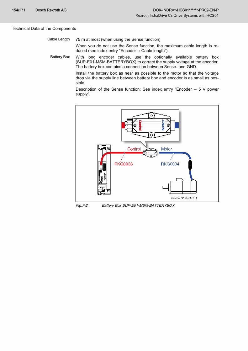
Cable Length 75 m at most (when using the Sense function)When you do not use the Sense function, the maximum cable length is re‐duced (see index entry "Encoder → Cable length").
Battery Box With long encoder cables, use the optionally available battery box(SUP‑E01‑MSM‑BATTERYBOX) to correct the supply voltage at the encoder.The battery box contains a connection between Sense- and GND.Install the battery box as near as possible to the motor so that the voltagedrop via the supply line between battery box and encoder is as small as pos‐sible.Description of the Sense function: See index entry "Encoder → 5 V powersupply".
Fig.7-2: Battery Box SUP‑E01‑MSM‑BATTERYBOX
Bosch Rexroth AG DOK-INDRV*-HCS01******-PR02-EN-P Rexroth IndraDrive Cs Drive Systems with HCS01
154/271
Technical Data of the Components
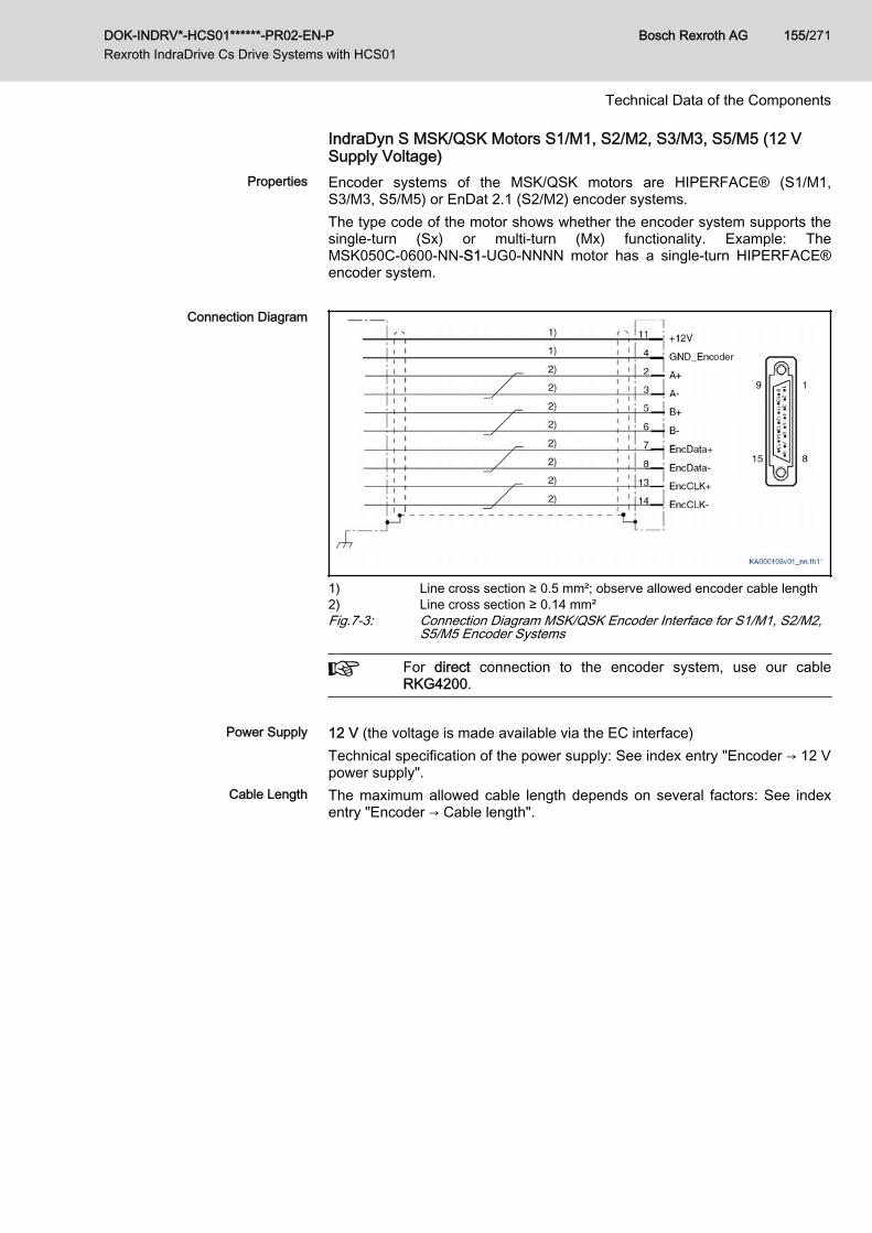
IndraDyn S MSK/QSK Motors S1/M1, S2/M2, S3/M3, S5/M5 (12 VSupply Voltage)
Properties Encoder systems of the MSK/QSK motors are HIPERFACE® (S1/M1,S3/M3, S5/M5) or EnDat 2.1 (S2/M2) encoder systems.The type code of the motor shows whether the encoder system supports thesingle-turn (Sx) or multi-turn (Mx) functionality. Example: TheMSK050C‑0600‑NN‑S1‑UG0‑NNNN motor has a single-turn HIPERFACE®encoder system.
Connection Diagram
1) Line cross section ≥ 0.5 mm²; observe allowed encoder cable length2) Line cross section ≥ 0.14 mm²Fig.7-3: Connection Diagram MSK/QSK Encoder Interface for S1/M1, S2/M2,
S5/M5 Encoder Systems
For direct connection to the encoder system, use our cableRKG4200.
Power Supply 12 V (the voltage is made available via the EC interface)
Technical specification of the power supply: See index entry "Encoder → 12 Vpower supply".
Cable Length The maximum allowed cable length depends on several factors: See indexentry "Encoder → Cable length".
DOK-INDRV*-HCS01******-PR02-EN-P Rexroth IndraDrive Cs Drive Systems with HCS01
Bosch Rexroth AG 155/271
Technical Data of the Components
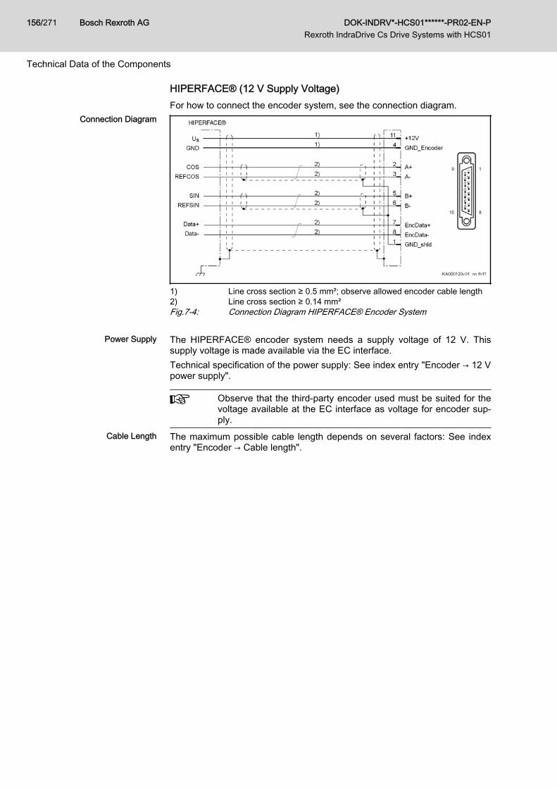
HIPERFACE® (12 V Supply Voltage)For how to connect the encoder system, see the connection diagram.
Connection Diagram
1) Line cross section ≥ 0.5 mm²; observe allowed encoder cable length2) Line cross section ≥ 0.14 mm²Fig.7-4: Connection Diagram HIPERFACE® Encoder System
Power Supply The HIPERFACE® encoder system needs a supply voltage of 12 V. Thissupply voltage is made available via the EC interface.Technical specification of the power supply: See index entry "Encoder → 12 Vpower supply".
Observe that the third-party encoder used must be suited for thevoltage available at the EC interface as voltage for encoder sup‐ply.
Cable Length The maximum possible cable length depends on several factors: See indexentry "Encoder → Cable length".
Bosch Rexroth AG DOK-INDRV*-HCS01******-PR02-EN-P Rexroth IndraDrive Cs Drive Systems with HCS01
156/271
Technical Data of the Components
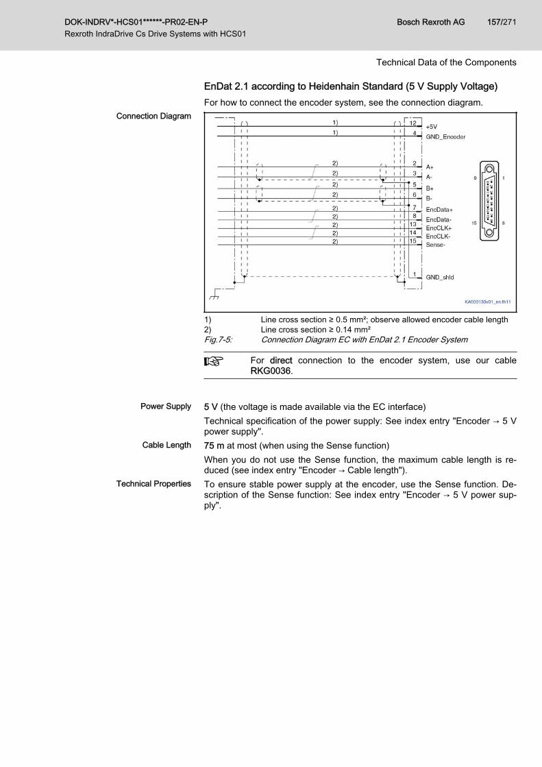
EnDat 2.1 according to Heidenhain Standard (5 V Supply Voltage)For how to connect the encoder system, see the connection diagram.
Connection Diagram
1) Line cross section ≥ 0.5 mm²; observe allowed encoder cable length2) Line cross section ≥ 0.14 mm²Fig.7-5: Connection Diagram EC with EnDat 2.1 Encoder System
For direct connection to the encoder system, use our cableRKG0036.
Power Supply 5 V (the voltage is made available via the EC interface)
Technical specification of the power supply: See index entry "Encoder → 5 Vpower supply".
Cable Length 75 m at most (when using the Sense function)When you do not use the Sense function, the maximum cable length is re‐duced (see index entry "Encoder → Cable length").
Technical Properties To ensure stable power supply at the encoder, use the Sense function. De‐scription of the Sense function: See index entry "Encoder → 5 V power sup‐ply".
DOK-INDRV*-HCS01******-PR02-EN-P Rexroth IndraDrive Cs Drive Systems with HCS01
Bosch Rexroth AG 157/271
Technical Data of the Components
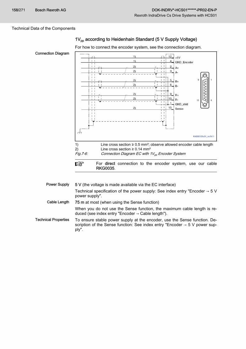
1Vpp according to Heidenhain Standard (5 V Supply Voltage)For how to connect the encoder system, see the connection diagram.
Connection Diagram
1) Line cross section ≥ 0.5 mm²; observe allowed encoder cable length2) Line cross section ≥ 0.14 mm²Fig.7-6: Connection Diagram EC with 1Vpp Encoder System
For direct connection to the encoder system, use our cableRKG0035.
Power Supply 5 V (the voltage is made available via the EC interface)
Technical specification of the power supply: See index entry "Encoder → 5 Vpower supply".
Cable Length 75 m at most (when using the Sense function)When you do not use the Sense function, the maximum cable length is re‐duced (see index entry "Encoder → Cable length").
Technical Properties To ensure stable power supply at the encoder, use the Sense function. De‐scription of the Sense function: See index entry "Encoder → 5 V power sup‐ply".
Bosch Rexroth AG DOK-INDRV*-HCS01******-PR02-EN-P Rexroth IndraDrive Cs Drive Systems with HCS01
158/271
Technical Data of the Components
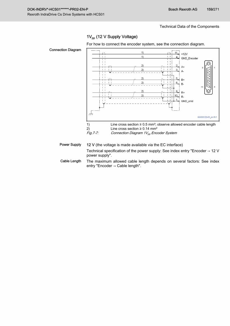
1Vpp (12 V Supply Voltage)For how to connect the encoder system, see the connection diagram.
Connection Diagram
1) Line cross section ≥ 0.5 mm²; observe allowed encoder cable length2) Line cross section ≥ 0.14 mm²Fig.7-7: Connection Diagram 1Vpp Encoder System
Power Supply 12 V (the voltage is made available via the EC interface)Technical specification of the power supply: See index entry "Encoder → 12 Vpower supply".
Cable Length The maximum allowed cable length depends on several factors: See indexentry "Encoder → Cable length".
DOK-INDRV*-HCS01******-PR02-EN-P Rexroth IndraDrive Cs Drive Systems with HCS01
Bosch Rexroth AG 159/271
Technical Data of the Components
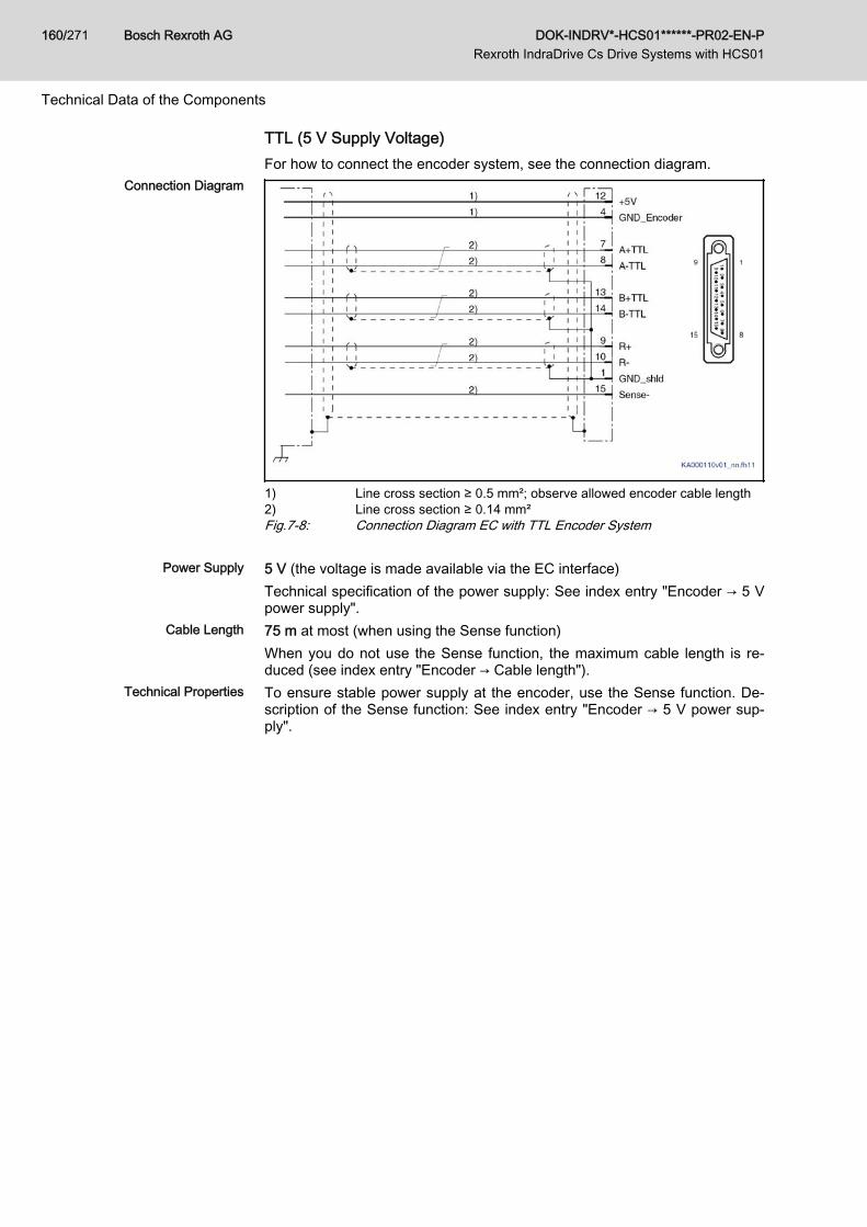
TTL (5 V Supply Voltage)For how to connect the encoder system, see the connection diagram.
Connection Diagram
1) Line cross section ≥ 0.5 mm²; observe allowed encoder cable length2) Line cross section ≥ 0.14 mm²Fig.7-8: Connection Diagram EC with TTL Encoder System
Power Supply 5 V (the voltage is made available via the EC interface)Technical specification of the power supply: See index entry "Encoder → 5 Vpower supply".
Cable Length 75 m at most (when using the Sense function)When you do not use the Sense function, the maximum cable length is re‐duced (see index entry "Encoder → Cable length").
Technical Properties To ensure stable power supply at the encoder, use the Sense function. De‐scription of the Sense function: See index entry "Encoder → 5 V power sup‐ply".
Bosch Rexroth AG DOK-INDRV*-HCS01******-PR02-EN-P Rexroth IndraDrive Cs Drive Systems with HCS01
160/271
Technical Data of the Components
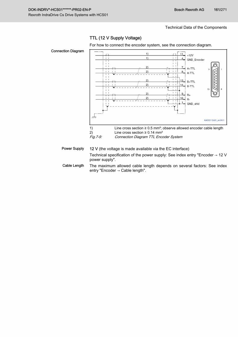
TTL (12 V Supply Voltage)For how to connect the encoder system, see the connection diagram.
Connection Diagram
1) Line cross section ≥ 0.5 mm²; observe allowed encoder cable length2) Line cross section ≥ 0.14 mm²Fig.7-9: Connection Diagram TTL Encoder System
Power Supply 12 V (the voltage is made available via the EC interface)Technical specification of the power supply: See index entry "Encoder → 12 Vpower supply".
Cable Length The maximum allowed cable length depends on several factors: See indexentry "Encoder → Cable length".
DOK-INDRV*-HCS01******-PR02-EN-P Rexroth IndraDrive Cs Drive Systems with HCS01
Bosch Rexroth AG 161/271
Technical Data of the Components
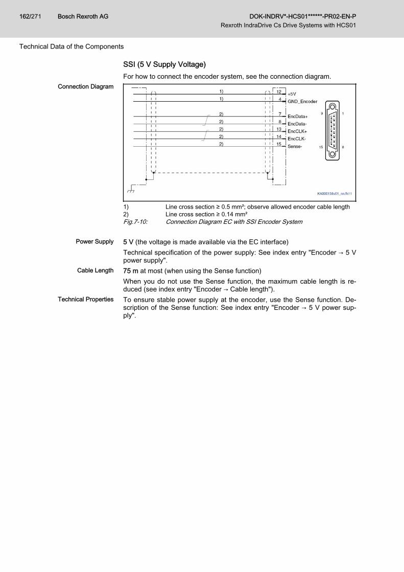
SSI (5 V Supply Voltage)For how to connect the encoder system, see the connection diagram.
Connection Diagram
1) Line cross section ≥ 0.5 mm²; observe allowed encoder cable length2) Line cross section ≥ 0.14 mm²Fig.7-10: Connection Diagram EC with SSI Encoder System
Power Supply 5 V (the voltage is made available via the EC interface)Technical specification of the power supply: See index entry "Encoder → 5 Vpower supply".
Cable Length 75 m at most (when using the Sense function)When you do not use the Sense function, the maximum cable length is re‐duced (see index entry "Encoder → Cable length").
Technical Properties To ensure stable power supply at the encoder, use the Sense function. De‐scription of the Sense function: See index entry "Encoder → 5 V power sup‐ply".
Bosch Rexroth AG DOK-INDRV*-HCS01******-PR02-EN-P Rexroth IndraDrive Cs Drive Systems with HCS01
162/271
Technical Data of the Components
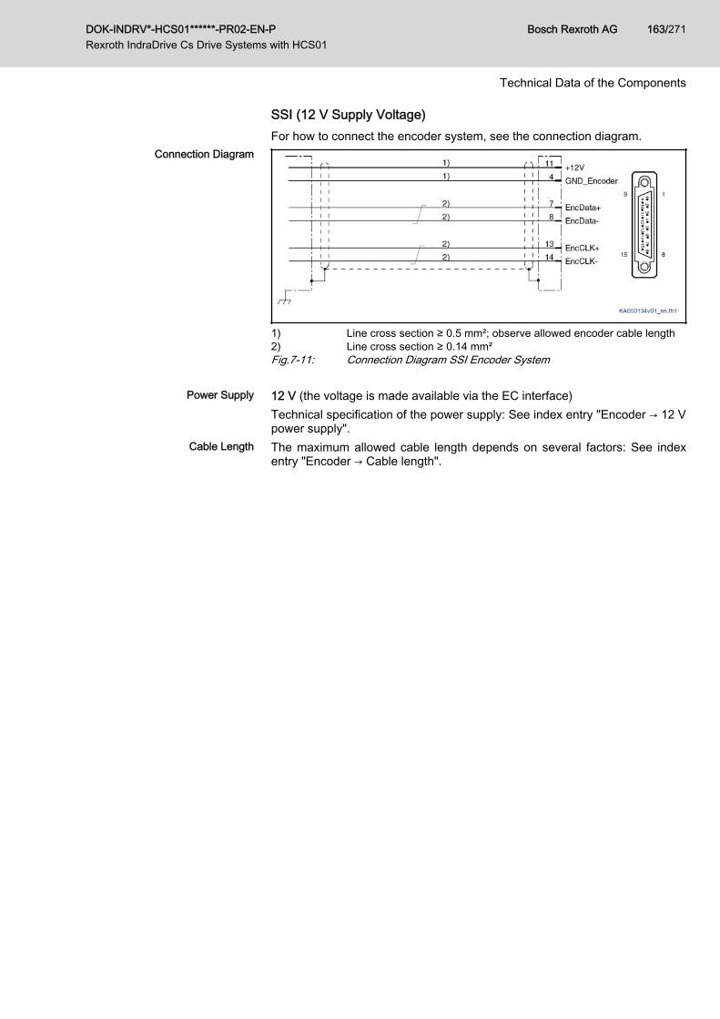
SSI (12 V Supply Voltage)For how to connect the encoder system, see the connection diagram.
Connection Diagram
1) Line cross section ≥ 0.5 mm²; observe allowed encoder cable length2) Line cross section ≥ 0.14 mm²Fig.7-11: Connection Diagram SSI Encoder System
Power Supply 12 V (the voltage is made available via the EC interface)Technical specification of the power supply: See index entry "Encoder → 12 Vpower supply".
Cable Length The maximum allowed cable length depends on several factors: See indexentry "Encoder → Cable length".
DOK-INDRV*-HCS01******-PR02-EN-P Rexroth IndraDrive Cs Drive Systems with HCS01
Bosch Rexroth AG 163/271
Technical Data of the Components
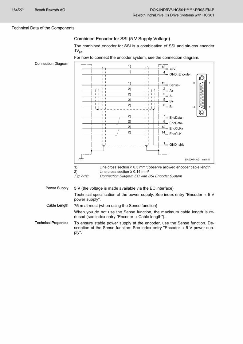
Combined Encoder for SSI (5 V Supply Voltage)The combined encoder for SSI is a combination of SSI and sin-cos encoder1Vpp.For how to connect the encoder system, see the connection diagram.
Connection Diagram
1) Line cross section ≥ 0.5 mm²; observe allowed encoder cable length2) Line cross section ≥ 0.14 mm²Fig.7-12: Connection Diagram EC with SSI Encoder System
Power Supply 5 V (the voltage is made available via the EC interface)Technical specification of the power supply: See index entry "Encoder → 5 Vpower supply".
Cable Length 75 m at most (when using the Sense function)When you do not use the Sense function, the maximum cable length is re‐duced (see index entry "Encoder → Cable length").
Technical Properties To ensure stable power supply at the encoder, use the Sense function. De‐scription of the Sense function: See index entry "Encoder → 5 V power sup‐ply".
Bosch Rexroth AG DOK-INDRV*-HCS01******-PR02-EN-P Rexroth IndraDrive Cs Drive Systems with HCS01
164/271
Technical Data of the Components
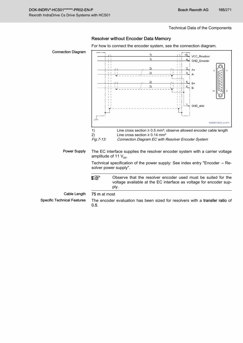
Resolver without Encoder Data MemoryFor how to connect the encoder system, see the connection diagram.
Connection Diagram
1) Line cross section ≥ 0.5 mm²; observe allowed encoder cable length2) Line cross section ≥ 0.14 mm²Fig.7-13: Connection Diagram EC with Resolver Encoder System
Power Supply The EC interface supplies the resolver encoder system with a carrier voltageamplitude of 11 Vpp.Technical specification of the power supply: See index entry "Encoder → Re‐solver power supply".
Observe that the resolver encoder used must be suited for thevoltage available at the EC interface as voltage for encoder sup‐ply.
Cable Length 75 m at mostSpecific Technical Features The encoder evaluation has been sized for resolvers with a transfer ratio of
0.5.
DOK-INDRV*-HCS01******-PR02-EN-P Rexroth IndraDrive Cs Drive Systems with HCS01
Bosch Rexroth AG 165/271
Technical Data of the Components
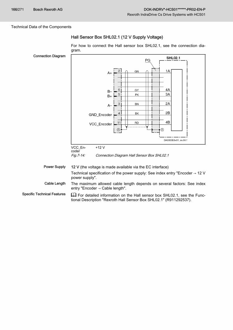
Hall Sensor Box SHL02.1 (12 V Supply Voltage)
For how to connect the Hall sensor box SHL02.1, see the connection dia‐gram.
Connection Diagram
VCC_En‐coder
+12 V
Fig.7-14: Connection Diagram Hall Sensor Box SHL02.1
Power Supply 12 V (the voltage is made available via the EC interface)Technical specification of the power supply: See index entry "Encoder → 12 Vpower supply".
Cable Length The maximum allowed cable length depends on several factors: See indexentry "Encoder → Cable length".
Specific Technical Features For detailed information on the Hall sensor box SHL02.1, see the Func‐tional Description "Rexroth Hall Sensor Box SHL02.1" (R911292537).
Bosch Rexroth AG DOK-INDRV*-HCS01******-PR02-EN-P Rexroth IndraDrive Cs Drive Systems with HCS01
166/271
Technical Data of the Components
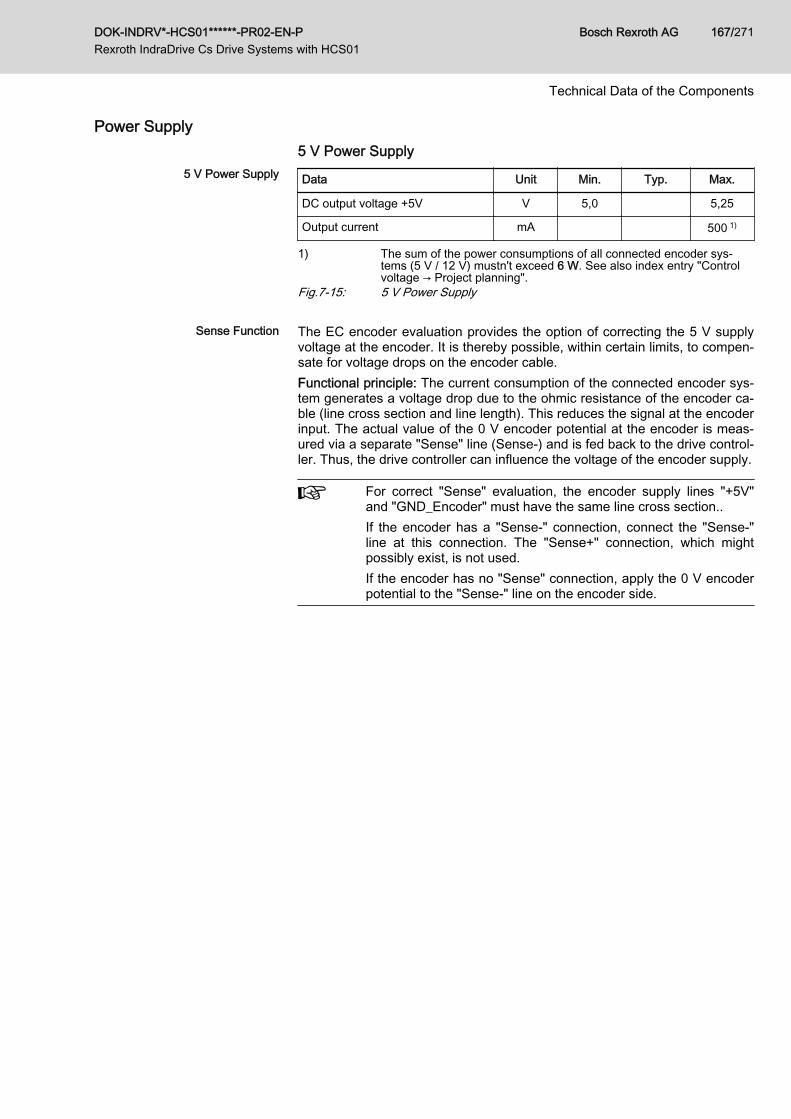
Power Supply5 V Power Supply
5 V Power Supply Data Unit Min. Typ. Max.
DC output voltage +5V V 5,0 5,25
Output current mA 500 1)
1) The sum of the power consumptions of all connected encoder sys‐tems (5 V / 12 V) mustn't exceed 6 W. See also index entry "Controlvoltage → Project planning".
Fig.7-15: 5 V Power Supply
Sense Function The EC encoder evaluation provides the option of correcting the 5 V supplyvoltage at the encoder. It is thereby possible, within certain limits, to compen‐sate for voltage drops on the encoder cable.Functional principle: The current consumption of the connected encoder sys‐tem generates a voltage drop due to the ohmic resistance of the encoder ca‐ble (line cross section and line length). This reduces the signal at the encoderinput. The actual value of the 0 V encoder potential at the encoder is meas‐ured via a separate "Sense" line (Sense-) and is fed back to the drive control‐ler. Thus, the drive controller can influence the voltage of the encoder supply.
For correct "Sense" evaluation, the encoder supply lines "+5V"and "GND_Encoder" must have the same line cross section..If the encoder has a "Sense‑" connection, connect the "Sense‑"line at this connection. The "Sense+" connection, which mightpossibly exist, is not used.If the encoder has no "Sense" connection, apply the 0 V encoderpotential to the "Sense‑" line on the encoder side.
DOK-INDRV*-HCS01******-PR02-EN-P Rexroth IndraDrive Cs Drive Systems with HCS01
Bosch Rexroth AG 167/271
Technical Data of the Components
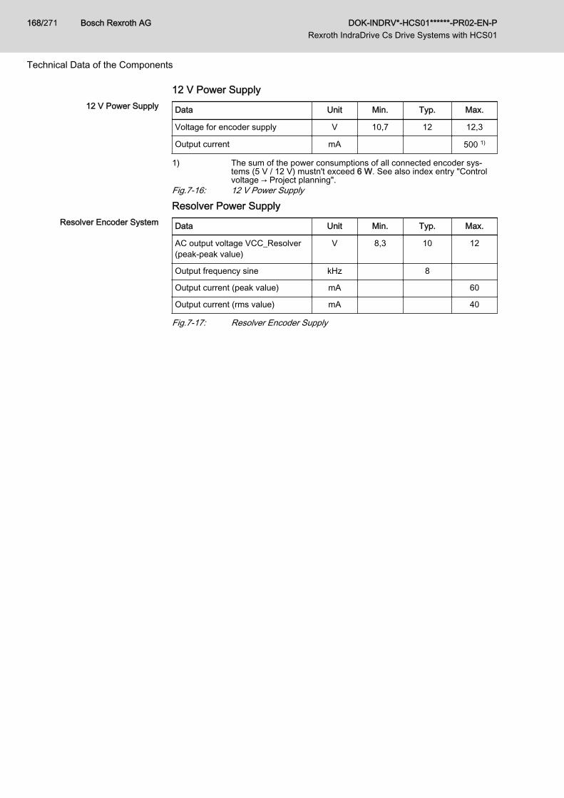
12 V Power Supply12 V Power Supply Data Unit Min. Typ. Max.
Voltage for encoder supply V 10,7 12 12,3
Output current mA 500 1)
1) The sum of the power consumptions of all connected encoder sys‐tems (5 V / 12 V) mustn't exceed 6 W. See also index entry "Controlvoltage → Project planning".
Fig.7-16: 12 V Power Supply
Resolver Power SupplyResolver Encoder System Data Unit Min. Typ. Max.
AC output voltage VCC_Resolver(peak‑peak value)
V 8,3 10 12
Output frequency sine kHz 8
Output current (peak value) mA 60
Output current (rms value) mA 40
Fig.7-17: Resolver Encoder Supply
Bosch Rexroth AG DOK-INDRV*-HCS01******-PR02-EN-P Rexroth IndraDrive Cs Drive Systems with HCS01
168/271
Technical Data of the Components
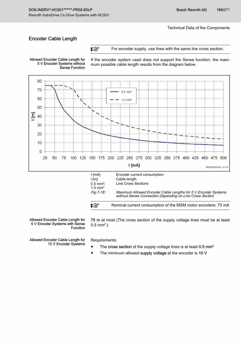
Encoder Cable Length
For encoder supply, use lines with the same line cross section.
Allowed Encoder Cable Length for5 V Encoder Systems without
Sense Function
If the encoder system used does not support the Sense function, the maxi‐mum possible cable length results from the diagram below.
I [mA] Encoder current consumptionl [m] Cable length0.5 mm2;1.0 mm2
Line Cross Sections
Fig.7-18: Maximum Allowed Encoder Cable Lengths for 5 V Encoder Systemswithout Sense Connection Depending on Line Cross Section
Nominal current consumption of the MSM motor encoders: 75 mA
Allowed Encoder Cable Length for5 V Encoder Systems with Sense
Function
75 m at most (The cross section of the supply voltage lines must be at least0.5 mm2.)
Allowed Encoder Cable Length for
12 V Encoder SystemsRequirements:● The cross section of the supply voltage lines is at least 0.5 mm2
● The minimum allowed supply voltage at the encoder is 10 V
DOK-INDRV*-HCS01******-PR02-EN-P Rexroth IndraDrive Cs Drive Systems with HCS01
Bosch Rexroth AG 169/271
Technical Data of the Components
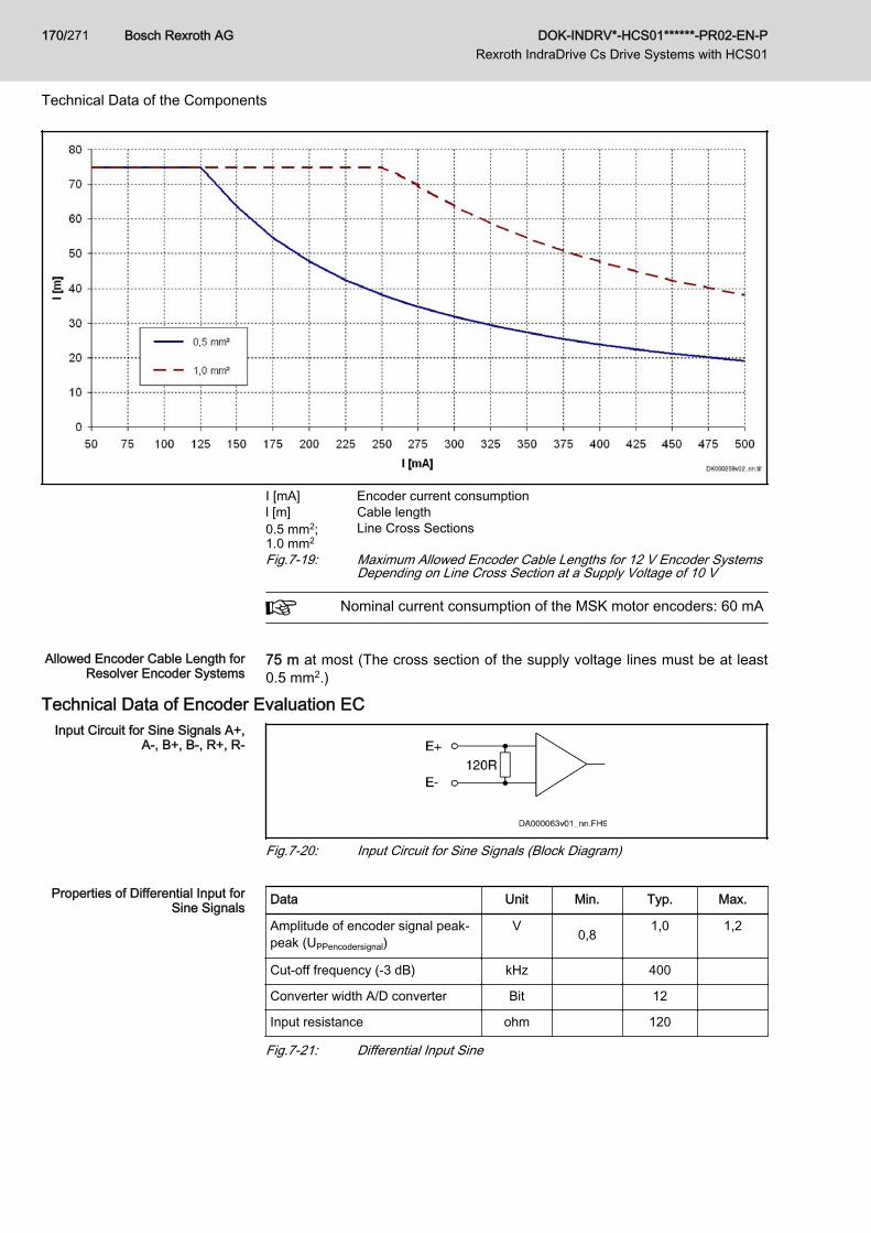
I [mA] Encoder current consumptionl [m] Cable length0.5 mm2;1.0 mm2
Line Cross Sections
Fig.7-19: Maximum Allowed Encoder Cable Lengths for 12 V Encoder SystemsDepending on Line Cross Section at a Supply Voltage of 10 V
Nominal current consumption of the MSK motor encoders: 60 mA
Allowed Encoder Cable Length for
Resolver Encoder Systems75 m at most (The cross section of the supply voltage lines must be at least0.5 mm2.)
Technical Data of Encoder Evaluation ECInput Circuit for Sine Signals A+,
A-, B+, B-, R+, R-
Fig.7-20: Input Circuit for Sine Signals (Block Diagram)
Properties of Differential Input forSine Signals Data Unit Min. Typ. Max.
Amplitude of encoder signal peak-peak (UPPencodersignal)
V 0,8 1,0 1,2
Cut-off frequency (-3 dB) kHz 400
Converter width A/D converter Bit 12
Input resistance ohm 120
Fig.7-21: Differential Input Sine
Bosch Rexroth AG DOK-INDRV*-HCS01******-PR02-EN-P Rexroth IndraDrive Cs Drive Systems with HCS01
170/271
Technical Data of the Components
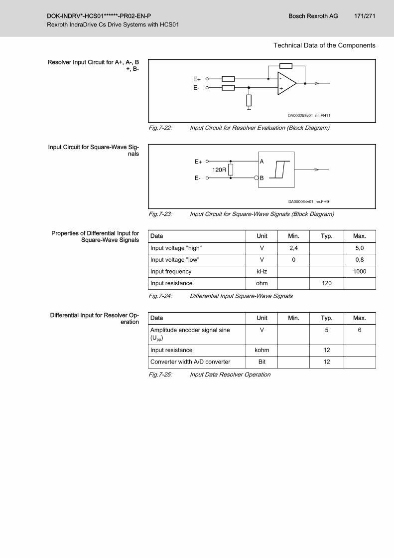
Resolver Input Circuit for A+, A-, B+, B-
Fig.7-22: Input Circuit for Resolver Evaluation (Block Diagram)
Input Circuit for Square-Wave Sig‐nals
Fig.7-23: Input Circuit for Square-Wave Signals (Block Diagram)
Properties of Differential Input forSquare-Wave Signals Data Unit Min. Typ. Max.
Input voltage "high" V 2,4 5,0
Input voltage "low" V 0 0,8
Input frequency kHz 1000
Input resistance ohm 120
Fig.7-24: Differential Input Square-Wave Signals
Differential Input for Resolver Op‐eration Data Unit Min. Typ. Max.
Amplitude encoder signal sine(Upp)
V 5 6
Input resistance kohm 12
Converter width A/D converter Bit 12
Fig.7-25: Input Data Resolver Operation
DOK-INDRV*-HCS01******-PR02-EN-P Rexroth IndraDrive Cs Drive Systems with HCS01
Bosch Rexroth AG 171/271
Technical Data of the Components
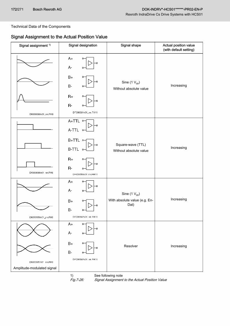
Signal Assignment to the Actual Position Value
Signal assignment 1) Signal designation Signal shape Actual position value(with default setting)
Sine (1 Vpp)
Without absolute valueIncreasing
Square-wave (TTL)Without absolute value
Increasing
Sine (1 Vpp)
With absolute value (e.g. En‐Dat)
Increasing
Amplitude-modulated signal
Resolver Increasing
1) See following noteFig.7-26: Signal Assignment to the Actual Position Value
Bosch Rexroth AG DOK-INDRV*-HCS01******-PR02-EN-P Rexroth IndraDrive Cs Drive Systems with HCS01
172/271
Technical Data of the Components
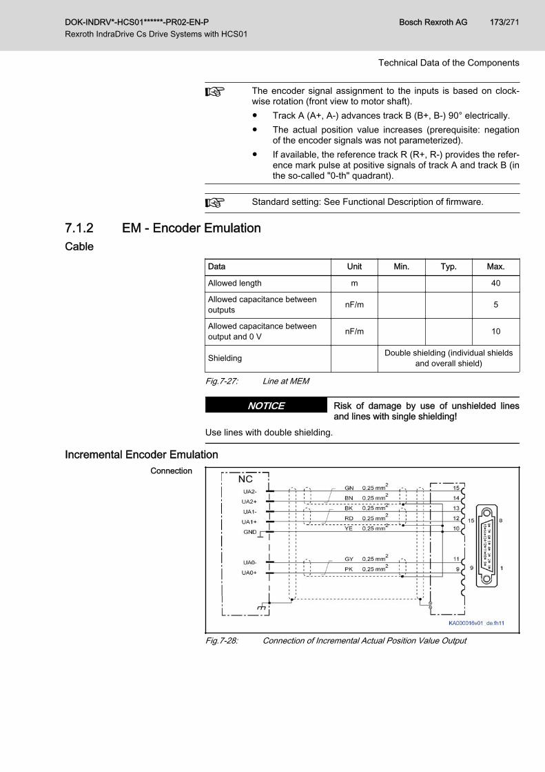
The encoder signal assignment to the inputs is based on clock‐wise rotation (front view to motor shaft).● Track A (A+, A-) advances track B (B+, B-) 90° electrically.● The actual position value increases (prerequisite: negation
of the encoder signals was not parameterized).● If available, the reference track R (R+, R-) provides the refer‐
ence mark pulse at positive signals of track A and track B (inthe so-called "0-th" quadrant).
Standard setting: See Functional Description of firmware.
7.1.2 EM - Encoder EmulationCable
Data Unit Min. Typ. Max.
Allowed length m 40
Allowed capacitance betweenoutputs nF/m 5
Allowed capacitance betweenoutput and 0 V nF/m 10
Shielding Double shielding (individual shieldsand overall shield)
Fig.7-27: Line at MEM
Risk of damage by use of unshielded linesand lines with single shielding!
NOTICE
Use lines with double shielding.
Incremental Encoder EmulationConnection
Fig.7-28: Connection of Incremental Actual Position Value Output
DOK-INDRV*-HCS01******-PR02-EN-P Rexroth IndraDrive Cs Drive Systems with HCS01
Bosch Rexroth AG 173/271
Technical Data of the Components
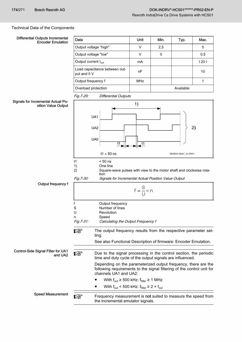
Differential Outputs IncrementalEncoder Emulation Data Unit Min. Typ. Max.
Output voltage "high" V 2,5 5
Output voltage "low" V 0 0,5
Output current Iout mA I 20 I
Load capacitance between out‐put and 0 V nF 10
Output frequency f MHz 1
Overload protection Available
Fig.7-29: Differential OutputsSignals for Incremental Actual Po‐
sition Value Output
t1 < 50 ns1) One line2) Square-wave pulses with view to the motor shaft and clockwise rota‐
tionFig.7-30: Signals for Incremental Actual Position Value Output
Output frequency f
f Output frequencyS Number of linesU Revolutionn SpeedFig.7-31: Calculating the Output Frequency f
The output frequency results from the respective parameter set‐ting.See also Functional Description of firmware: Encoder Emulation.
Control-Side Signal Filter for UA1and UA2 Due to the signal processing in the control section, the periodic
time and duty cycle of the output signals are influenced.Depending on the parameterized output frequency, there are thefollowing requirements to the signal filtering of the control unit forchannels UA1 and UA2:● With fout ≥ 500 kHz: ffilter ≥ 1 MHz● With fout < 500 kHz: ffilter ≥ 2 × fout
Speed Measurement Frequency measurement is not suited to measure the speed fromthe incremental emulator signals.
Bosch Rexroth AG DOK-INDRV*-HCS01******-PR02-EN-P Rexroth IndraDrive Cs Drive Systems with HCS01
174/271
Technical Data of the Components
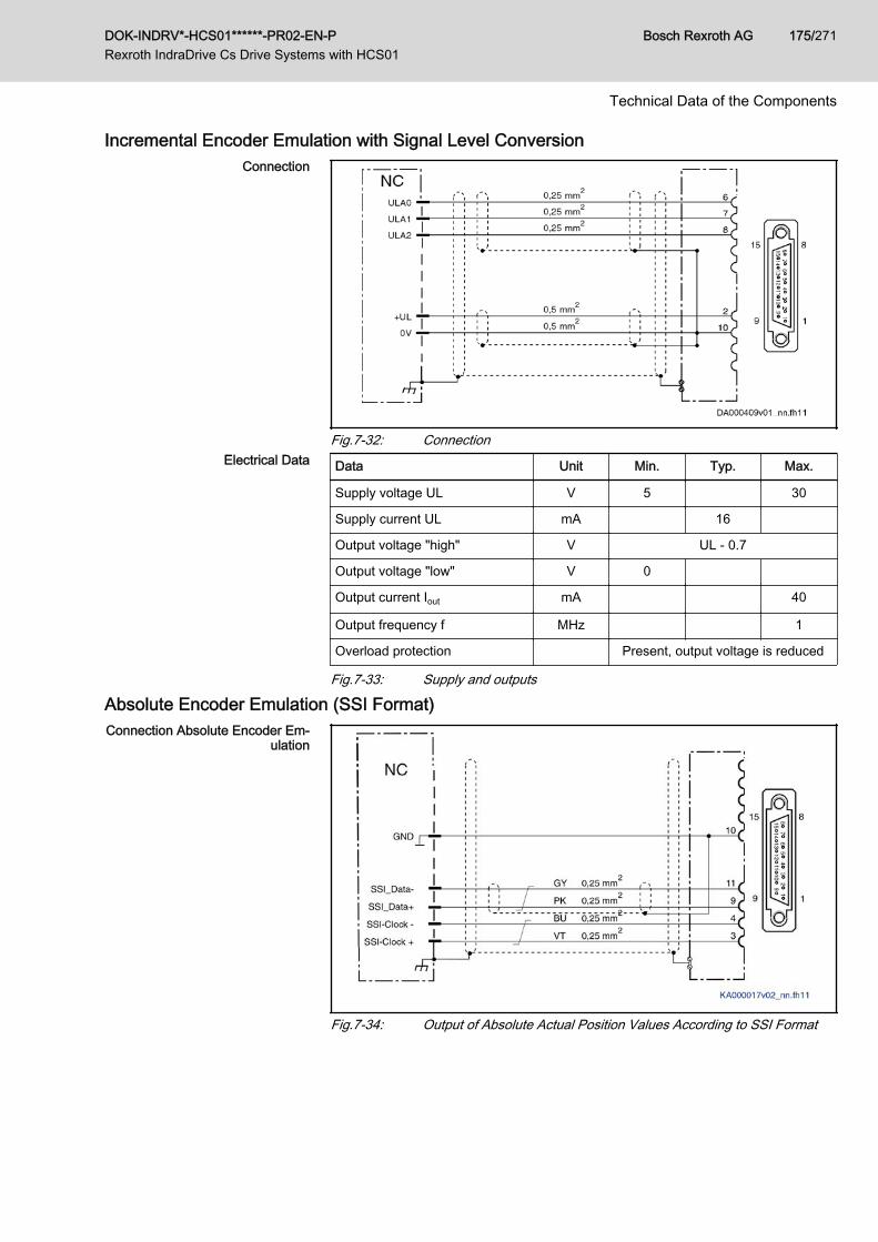
Incremental Encoder Emulation with Signal Level ConversionConnection
Fig.7-32: ConnectionElectrical Data Data Unit Min. Typ. Max.
Supply voltage UL V 5 30
Supply current UL mA 16
Output voltage "high" V UL - 0.7
Output voltage "low" V 0
Output current Iout mA 40
Output frequency f MHz 1
Overload protection Present, output voltage is reduced
Fig.7-33: Supply and outputs
Absolute Encoder Emulation (SSI Format)Connection Absolute Encoder Em‐
ulation
Fig.7-34: Output of Absolute Actual Position Values According to SSI Format
DOK-INDRV*-HCS01******-PR02-EN-P Rexroth IndraDrive Cs Drive Systems with HCS01
Bosch Rexroth AG 175/271
Technical Data of the Components
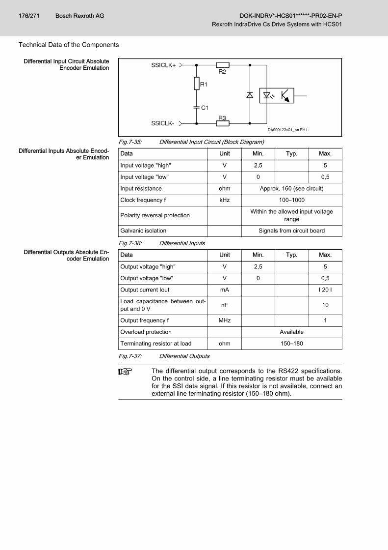
Differential Input Circuit AbsoluteEncoder Emulation
Fig.7-35: Differential Input Circuit (Block Diagram)Differential Inputs Absolute Encod‐
er Emulation Data Unit Min. Typ. Max.
Input voltage "high" V 2,5 5
Input voltage "low" V 0 0,5
Input resistance ohm Approx. 160 (see circuit)
Clock frequency f kHz 100–1000
Polarity reversal protection Within the allowed input voltagerange
Galvanic isolation Signals from circuit board
Fig.7-36: Differential InputsDifferential Outputs Absolute En‐
coder Emulation Data Unit Min. Typ. Max.
Output voltage "high" V 2,5 5
Output voltage "low" V 0 0,5
Output current Iout mA I 20 I
Load capacitance between out‐put and 0 V nF 10
Output frequency f MHz 1
Overload protection Available
Terminating resistor at load ohm 150–180
Fig.7-37: Differential Outputs
The differential output corresponds to the RS422 specifications.On the control side, a line terminating resistor must be availablefor the SSI data signal. If this resistor is not available, connect anexternal line terminating resistor (150–180 ohm).
Bosch Rexroth AG DOK-INDRV*-HCS01******-PR02-EN-P Rexroth IndraDrive Cs Drive Systems with HCS01
176/271
Technical Data of the Components
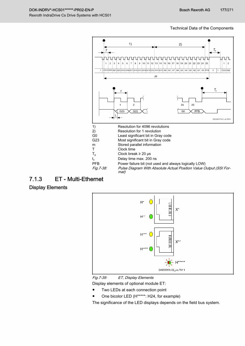
1) Resolution for 4096 revolutions2) Resolution for 1 revolutionG0 Least significant bit in Gray codeG23 Most significant bit in Gray codem Stored parallel informationT Clock timeTp Clock break ≥ 20 μstv Delay time max. 200 nsPFB Power failure bit (not used and always logically LOW)Fig.7-38: Pulse Diagram With Absolute Actual Position Value Output (SSI For‐
mat)
7.1.3 ET - Multi-EthernetDisplay Elements
Fig.7-39: ET, Display ElementsDisplay elements of optional module ET:● Two LEDs at each connection point● One bicolor LED (H*****: H24, for example)The significance of the LED displays depends on the field bus system.
DOK-INDRV*-HCS01******-PR02-EN-P Rexroth IndraDrive Cs Drive Systems with HCS01
Bosch Rexroth AG 177/271
Technical Data of the Components
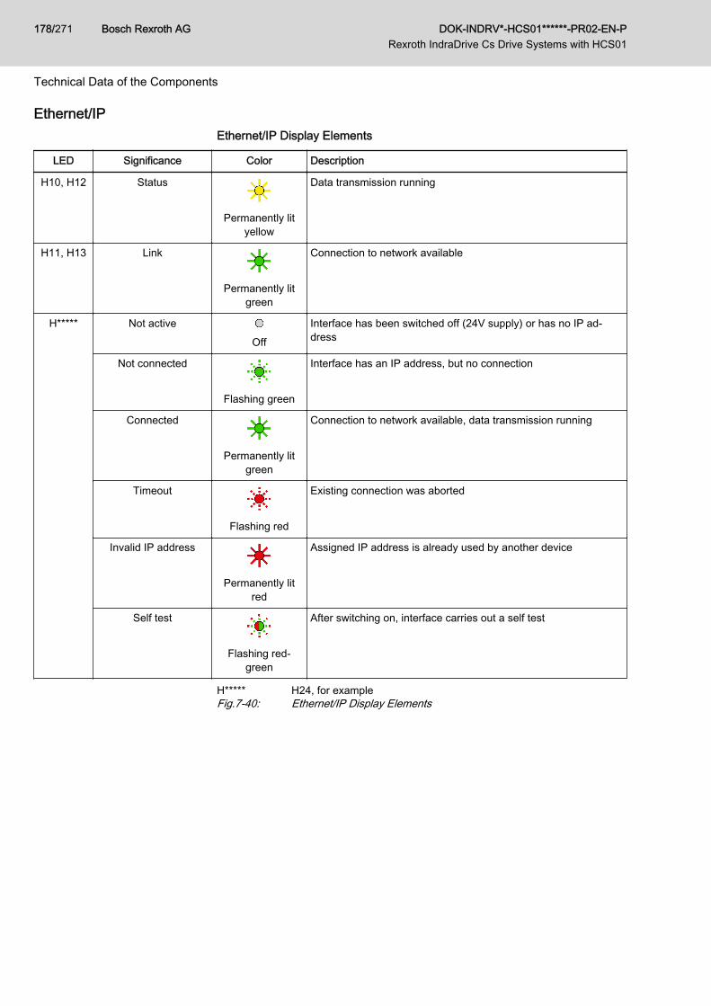
Ethernet/IPEthernet/IP Display Elements
LED Significance Color Description
H10, H12 Status
Permanently lityellow
Data transmission running
H11, H13 Link
Permanently litgreen
Connection to network available
H***** Not active
Off
Interface has been switched off (24V supply) or has no IP ad‐dress
Not connected
Flashing green
Interface has an IP address, but no connection
Connected
Permanently litgreen
Connection to network available, data transmission running
Timeout
Flashing red
Existing connection was aborted
Invalid IP address
Permanently litred
Assigned IP address is already used by another device
Self test
Flashing red-green
After switching on, interface carries out a self test
H***** H24, for exampleFig.7-40: Ethernet/IP Display Elements
Bosch Rexroth AG DOK-INDRV*-HCS01******-PR02-EN-P Rexroth IndraDrive Cs Drive Systems with HCS01
178/271
Technical Data of the Components
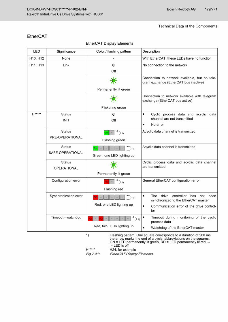
EtherCATEtherCAT Display Elements
LED Significance Color / flashing pattern Description
H10, H12 None - With EtherCAT, these LEDs have no function
H11, H13 Link
Off
No connection to the network
Permanently lit green
Connection to network available, but no tele‐gram exchange (EtherCAT bus inactive)
Flickering green
Connection to network available with telegramexchange (EtherCAT bus active)
H***** StatusINIT Off
● Cyclic process data and acyclic datachannel are not transmitted
● No error
StatusPRE-OPERATIONAL
1)
Flashing green
Acyclic data channel is transmitted
StatusSAFE-OPERATIONAL
1)
Green, one LED lighting up
Acyclic data channel is transmitted
StatusOPERATIONAL
Permanently lit green
Cyclic process data and acyclic data channelare transmitted
Configuration error 1)
Flashing red
General EtherCAT configuration error
Synchronization error 1)
Red, one LED lighting up
● The drive controller has not beensynchronized to the EtherCAT master
● Communication error of the drive control‐ler
Timeout - watchdog 1)
Red, two LEDs lighting up
● Timeout during monitoring of the cyclicprocess data
● Watchdog of the EtherCAT master
1) Flashing pattern: One square corresponds to a duration of 200 ms;the arrow marks the end of a cycle; abbreviations on the squares:GN = LED permanently lit green, RD = LED permanently lit red, -- = LED is off
H***** H24, for exampleFig.7-41: EtherCAT Display Elements
DOK-INDRV*-HCS01******-PR02-EN-P Rexroth IndraDrive Cs Drive Systems with HCS01
Bosch Rexroth AG 179/271
Technical Data of the Components
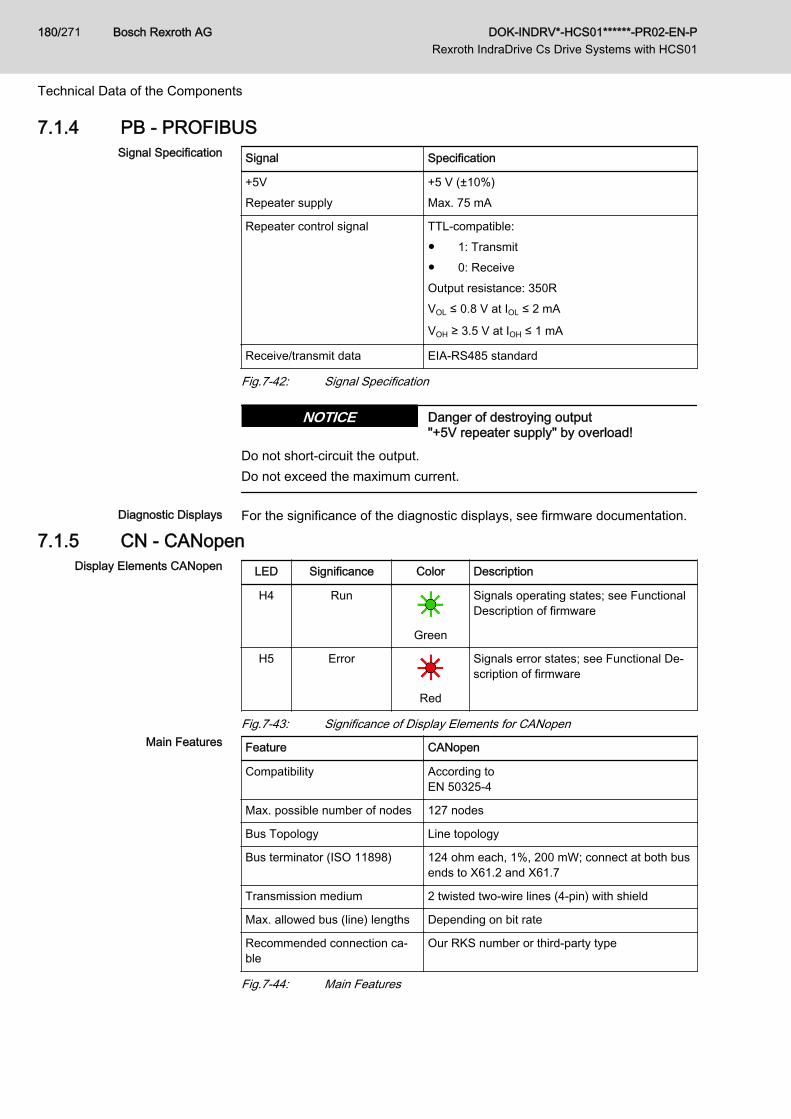
7.1.4 PB - PROFIBUSSignal Specification Signal Specification
+5VRepeater supply
+5 V (±10%)Max. 75 mA
Repeater control signal TTL-compatible:● 1: Transmit● 0: ReceiveOutput resistance: 350RVOL ≤ 0.8 V at IOL ≤ 2 mA
VOH ≥ 3.5 V at IOH ≤ 1 mA
Receive/transmit data EIA-RS485 standard
Fig.7-42: Signal Specification
Danger of destroying output "+5V repeater supply" by overload!
NOTICE
Do not short-circuit the output.Do not exceed the maximum current.
Diagnostic Displays For the significance of the diagnostic displays, see firmware documentation.
7.1.5 CN - CANopenDisplay Elements CANopen LED Significance Color Description
H4 Run
Green
Signals operating states; see FunctionalDescription of firmware
H5 Error
Red
Signals error states; see Functional De‐scription of firmware
Fig.7-43: Significance of Display Elements for CANopenMain Features Feature CANopen
Compatibility According to EN 50325-4
Max. possible number of nodes 127 nodes
Bus Topology Line topology
Bus terminator (ISO 11898) 124 ohm each, 1%, 200 mW; connect at both busends to X61.2 and X61.7
Transmission medium 2 twisted two-wire lines (4-pin) with shield
Max. allowed bus (line) lengths Depending on bit rate
Recommended connection ca‐ble
Our RKS number or third-party type
Fig.7-44: Main Features
Bosch Rexroth AG DOK-INDRV*-HCS01******-PR02-EN-P Rexroth IndraDrive Cs Drive Systems with HCS01
180/271
Technical Data of the Components
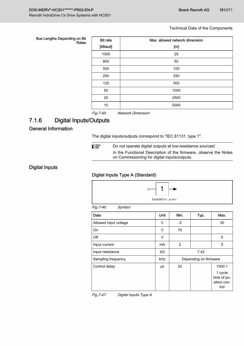
Bus Lengths Depending on BitRates Bit rate
[kBaud]Max. allowed network dimension
[m]
1000 25
800 50
500 100
250 250
125 500
50 1000
20 2500
10 5000
Fig.7-45: Network Dimension
7.1.6 Digital Inputs/OutputsGeneral Information
The digital inputs/outputs correspond to "IEC 61131, type 1".
Do not operate digital outputs at low-resistance sources!In the Functional Description of the firmware, observe the Noteson Commissioning for digital inputs/outputs.
Digital InputsDigital Inputs Type A (Standard)
Fig.7-46: Symbol
Data Unit Min. Typ. Max.
Allowed input voltage V -3 30
On V 15
Off V 5
Input current mA 2 5
Input resistance kΩ 7,42
Sampling frequency kHz Depending on firmware
Control delay μs 20 1000 +1 cycle
time of po‐sition con‐
trol
Fig.7-47: Digital Inputs Type A
DOK-INDRV*-HCS01******-PR02-EN-P Rexroth IndraDrive Cs Drive Systems with HCS01
Bosch Rexroth AG 181/271
Technical Data of the Components
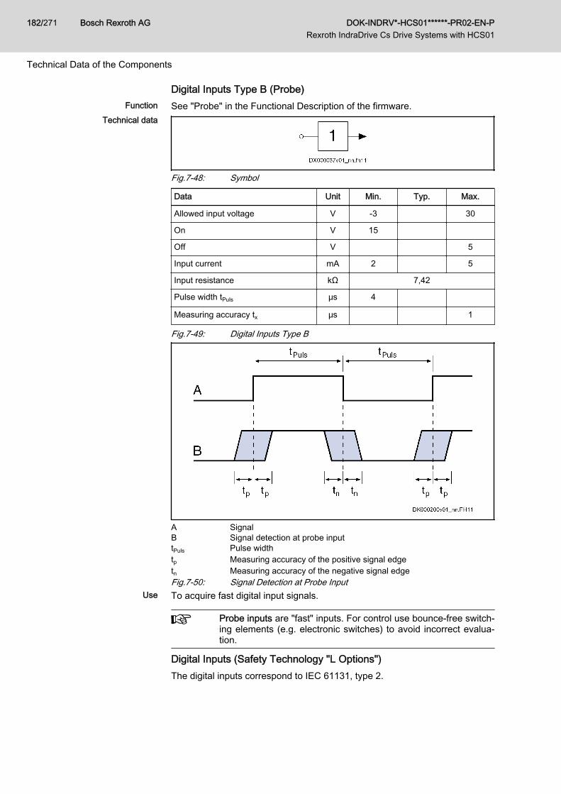
Digital Inputs Type B (Probe)Function See "Probe" in the Functional Description of the firmware.
Technical data
Fig.7-48: Symbol
Data Unit Min. Typ. Max.
Allowed input voltage V -3 30
On V 15
Off V 5
Input current mA 2 5
Input resistance kΩ 7,42
Pulse width tPuls μs 4
Measuring accuracy tx μs 1
Fig.7-49: Digital Inputs Type B
A SignalB Signal detection at probe inputtPuls Pulse widthtp Measuring accuracy of the positive signal edgetn Measuring accuracy of the negative signal edgeFig.7-50: Signal Detection at Probe Input
Use To acquire fast digital input signals.
Probe inputs are "fast" inputs. For control use bounce-free switch‐ing elements (e.g. electronic switches) to avoid incorrect evalua‐tion.
Digital Inputs (Safety Technology "L Options")The digital inputs correspond to IEC 61131, type 2.
Bosch Rexroth AG DOK-INDRV*-HCS01******-PR02-EN-P Rexroth IndraDrive Cs Drive Systems with HCS01
182/271
Technical Data of the Components
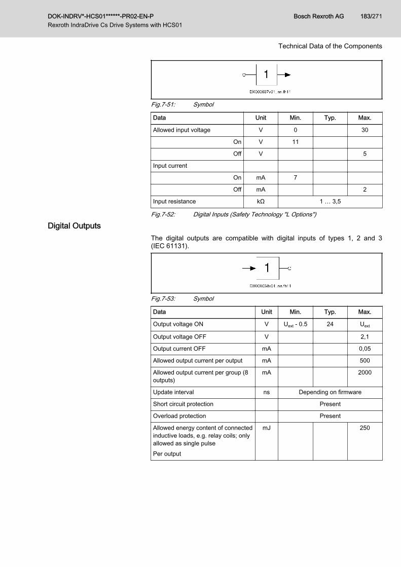
Fig.7-51: Symbol
Data Unit Min. Typ. Max.
Allowed input voltage V 0 30
On V 11
Off V 5
Input current
On mA 7
Off mA 2
Input resistance kΩ 1 … 3,5
Fig.7-52: Digital Inputs (Safety Technology "L Options")
Digital OutputsThe digital outputs are compatible with digital inputs of types 1, 2 and 3(IEC 61131).
Fig.7-53: Symbol
Data Unit Min. Typ. Max.
Output voltage ON V Uext - 0.5 24 Uext
Output voltage OFF V 2,1
Output current OFF mA 0,05
Allowed output current per output mA 500
Allowed output current per group (8outputs)
mA 2000
Update interval ns Depending on firmware
Short circuit protection Present
Overload protection Present
Allowed energy content of connectedinductive loads, e.g. relay coils; onlyallowed as single pulsePer output
mJ 250
DOK-INDRV*-HCS01******-PR02-EN-P Rexroth IndraDrive Cs Drive Systems with HCS01
Bosch Rexroth AG 183/271
Technical Data of the Components
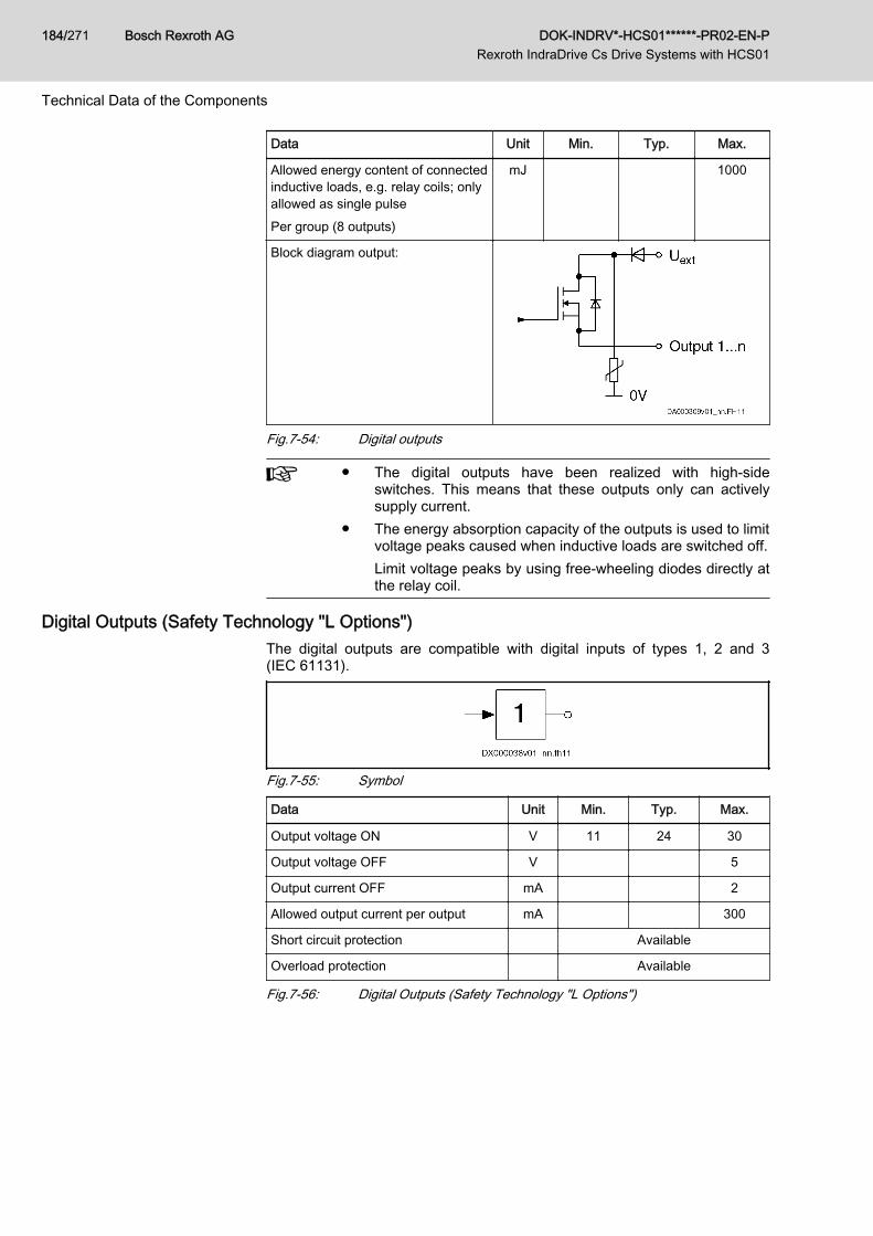
Data Unit Min. Typ. Max.
Allowed energy content of connectedinductive loads, e.g. relay coils; onlyallowed as single pulsePer group (8 outputs)
mJ 1000
Block diagram output:
Fig.7-54: Digital outputs
● The digital outputs have been realized with high-sideswitches. This means that these outputs only can activelysupply current.
● The energy absorption capacity of the outputs is used to limitvoltage peaks caused when inductive loads are switched off.Limit voltage peaks by using free-wheeling diodes directly atthe relay coil.
Digital Outputs (Safety Technology "L Options")The digital outputs are compatible with digital inputs of types 1, 2 and 3(IEC 61131).
Fig.7-55: Symbol
Data Unit Min. Typ. Max.
Output voltage ON V 11 24 30
Output voltage OFF V 5
Output current OFF mA 2
Allowed output current per output mA 300
Short circuit protection Available
Overload protection Available
Fig.7-56: Digital Outputs (Safety Technology "L Options")
Bosch Rexroth AG DOK-INDRV*-HCS01******-PR02-EN-P Rexroth IndraDrive Cs Drive Systems with HCS01
184/271
Technical Data of the Components
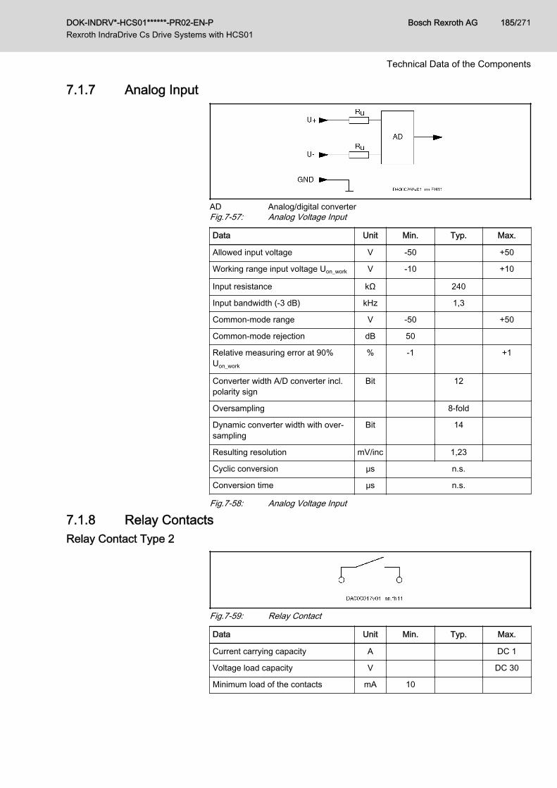
7.1.7 Analog Input
AD Analog/digital converterFig.7-57: Analog Voltage Input
Data Unit Min. Typ. Max.
Allowed input voltage V -50 +50
Working range input voltage Uon_work V -10 +10
Input resistance kΩ 240
Input bandwidth (-3 dB) kHz 1,3
Common-mode range V -50 +50
Common-mode rejection dB 50
Relative measuring error at 90%Uon_work
% -1 +1
Converter width A/D converter incl.polarity sign
Bit 12
Oversampling 8-fold
Dynamic converter width with over‐sampling
Bit 14
Resulting resolution mV/inc 1,23
Cyclic conversion μs n.s.
Conversion time μs n.s.
Fig.7-58: Analog Voltage Input
7.1.8 Relay ContactsRelay Contact Type 2
Fig.7-59: Relay Contact
Data Unit Min. Typ. Max.
Current carrying capacity A DC 1
Voltage load capacity V DC 30
Minimum load of the contacts mA 10
DOK-INDRV*-HCS01******-PR02-EN-P Rexroth IndraDrive Cs Drive Systems with HCS01
Bosch Rexroth AG 185/271
Technical Data of the Components
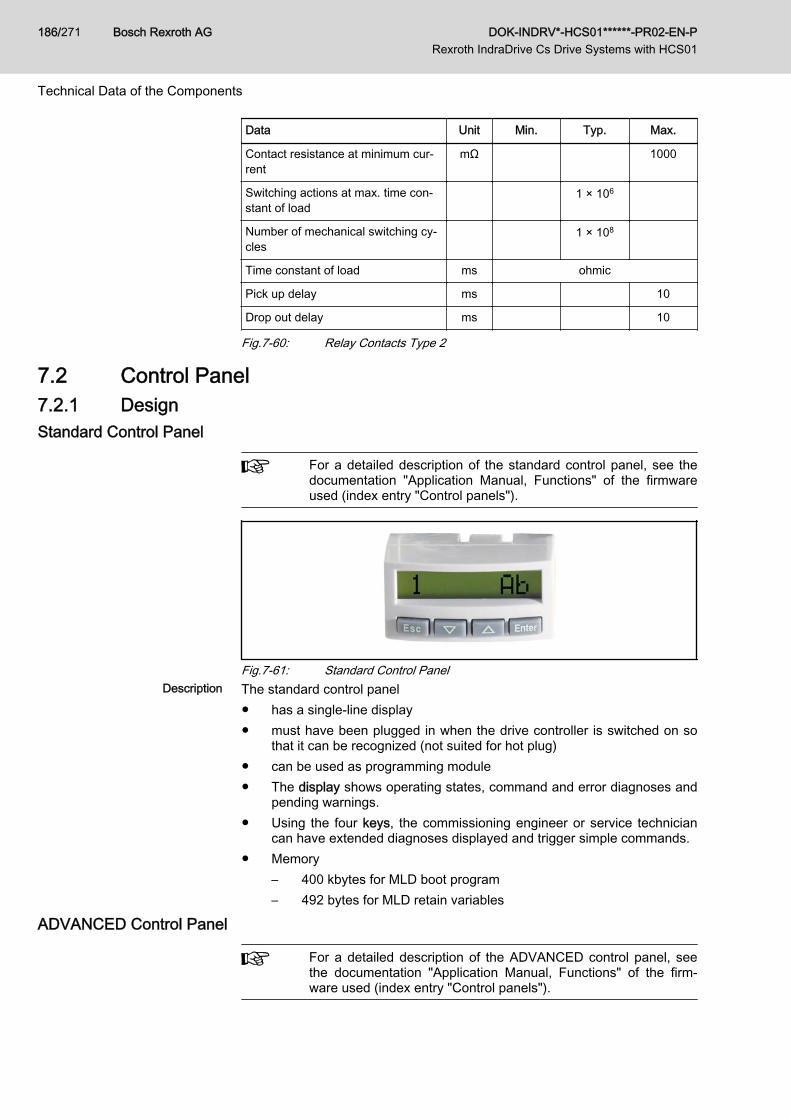
Data Unit Min. Typ. Max.
Contact resistance at minimum cur‐rent
mΩ 1000
Switching actions at max. time con‐stant of load
1 × 10⁶
Number of mechanical switching cy‐cles
1 × 10⁸
Time constant of load ms ohmic
Pick up delay ms 10
Drop out delay ms 10
Fig.7-60: Relay Contacts Type 2
7.2 Control Panel7.2.1 DesignStandard Control Panel
For a detailed description of the standard control panel, see thedocumentation "Application Manual, Functions" of the firmwareused (index entry "Control panels").
Fig.7-61: Standard Control PanelDescription The standard control panel
● has a single-line display● must have been plugged in when the drive controller is switched on so
that it can be recognized (not suited for hot plug)● can be used as programming module● The display shows operating states, command and error diagnoses and
pending warnings.● Using the four keys, the commissioning engineer or service technician
can have extended diagnoses displayed and trigger simple commands.● Memory
– 400 kbytes for MLD boot program– 492 bytes for MLD retain variables
ADVANCED Control Panel
For a detailed description of the ADVANCED control panel, seethe documentation "Application Manual, Functions" of the firm‐ware used (index entry "Control panels").
Bosch Rexroth AG DOK-INDRV*-HCS01******-PR02-EN-P Rexroth IndraDrive Cs Drive Systems with HCS01
186/271
Technical Data of the Components

Fig.7-62: ADVANCED Control PanelDescription The ADVANCED control panel
● has a slot for a microSD memory card (PFM04.1)● has a single-line display● must have been plugged in when the drive controller is switched on so
that it can be recognized (not suited for hot plug)● can be used as programming module● The display shows operating states, command and error diagnoses and
pending warnings.● Using the four keys, the commissioning engineer or service technician
can have extended diagnoses displayed and trigger simple commands.● Memory
– 400 kbytes for MLD boot program(4 MB with optional microSD memory card)
– 31724 bytes for MLD retain variables
7.3 Power Section7.3.1 Control Voltage
Data for Control Voltage Supply
Description Symbol UnitHCS01.1E-W0003-
_-02
HCS01.1E-W0006-
_-02
HCS01.1E-W0009-
_-02
HCS01.1E-W0013-
_-02
HCS01.1E-W0018-
_-02
Rated control voltage input (UL)1) UN3 V 24 ± 20%
Control voltage when using motorholding brake with motor cablelength < 50 m (HCS01< 40 m)2)
UN3 V 24 ± 5%
Control voltage when using motorholding brake with motor cablelength > 50 m3)
UN3 V 26 ± 5%
Maximum inrush current at 24Vsupply IEIN3_max A 3,30
Pulse width of IEIN3 tEIN3Lade ms 2
Last modification: 2012-01-23
DOK-INDRV*-HCS01******-PR02-EN-P Rexroth IndraDrive Cs Drive Systems with HCS01
Bosch Rexroth AG 187/271
Technical Data of the Components
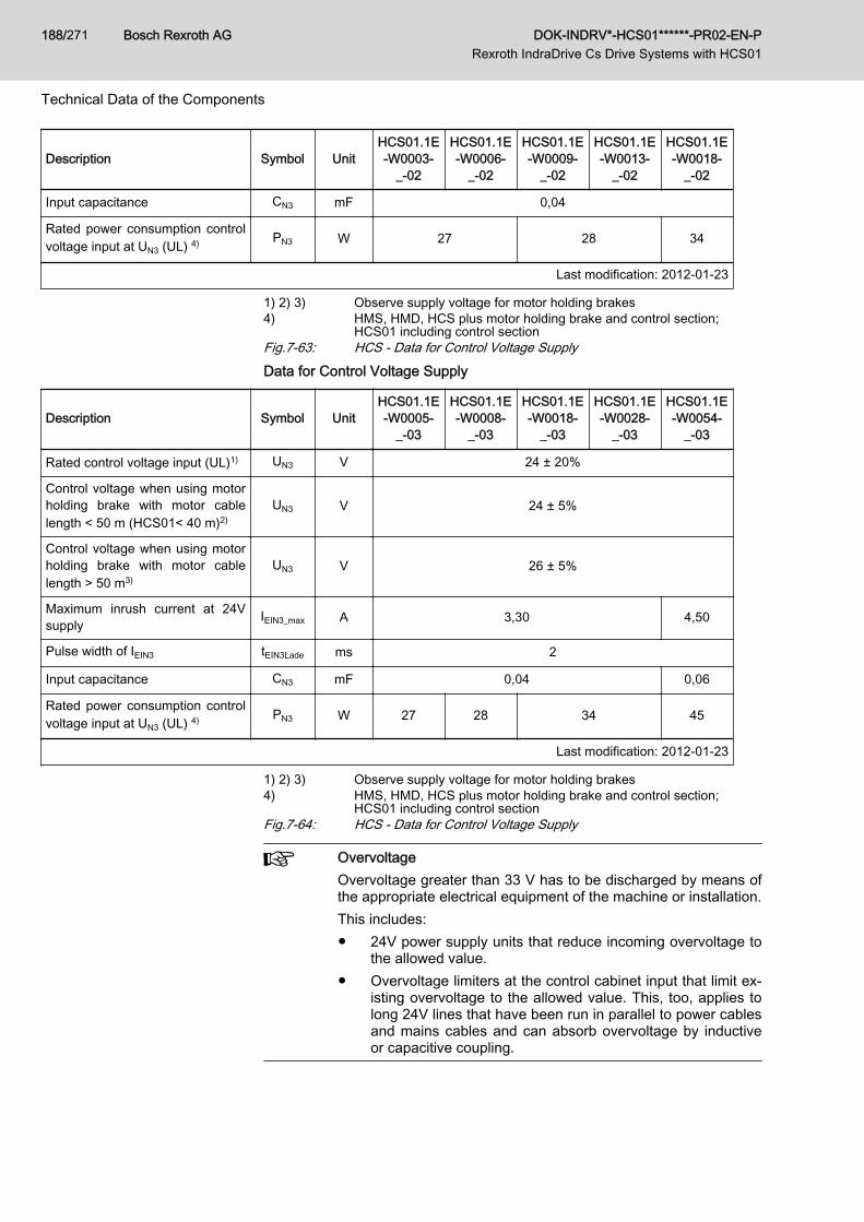
Description Symbol UnitHCS01.1E-W0003-
_-02
HCS01.1E-W0006-
_-02
HCS01.1E-W0009-
_-02
HCS01.1E-W0013-
_-02
HCS01.1E-W0018-
_-02
Input capacitance CN3 mF 0,04
Rated power consumption controlvoltage input at UN3 (UL) 4) PN3 W 27 28 34
Last modification: 2012-01-23
1) 2) 3) Observe supply voltage for motor holding brakes4) HMS, HMD, HCS plus motor holding brake and control section;
HCS01 including control sectionFig.7-63: HCS - Data for Control Voltage SupplyData for Control Voltage Supply
Description Symbol UnitHCS01.1E-W0005-
_-03
HCS01.1E-W0008-
_-03
HCS01.1E-W0018-
_-03
HCS01.1E-W0028-
_-03
HCS01.1E-W0054-
_-03
Rated control voltage input (UL)1) UN3 V 24 ± 20%
Control voltage when using motorholding brake with motor cablelength < 50 m (HCS01< 40 m)2)
UN3 V 24 ± 5%
Control voltage when using motorholding brake with motor cablelength > 50 m3)
UN3 V 26 ± 5%
Maximum inrush current at 24Vsupply IEIN3_max A 3,30 4,50
Pulse width of IEIN3 tEIN3Lade ms 2
Input capacitance CN3 mF 0,04 0,06
Rated power consumption controlvoltage input at UN3 (UL) 4) PN3 W 27 28 34 45
Last modification: 2012-01-23
1) 2) 3) Observe supply voltage for motor holding brakes4) HMS, HMD, HCS plus motor holding brake and control section;
HCS01 including control sectionFig.7-64: HCS - Data for Control Voltage Supply
OvervoltageOvervoltage greater than 33 V has to be discharged by means ofthe appropriate electrical equipment of the machine or installation.This includes:● 24V power supply units that reduce incoming overvoltage to
the allowed value.● Overvoltage limiters at the control cabinet input that limit ex‐
isting overvoltage to the allowed value. This, too, applies tolong 24V lines that have been run in parallel to power cablesand mains cables and can absorb overvoltage by inductiveor capacitive coupling.
Bosch Rexroth AG DOK-INDRV*-HCS01******-PR02-EN-P Rexroth IndraDrive Cs Drive Systems with HCS01
188/271
Technical Data of the Components
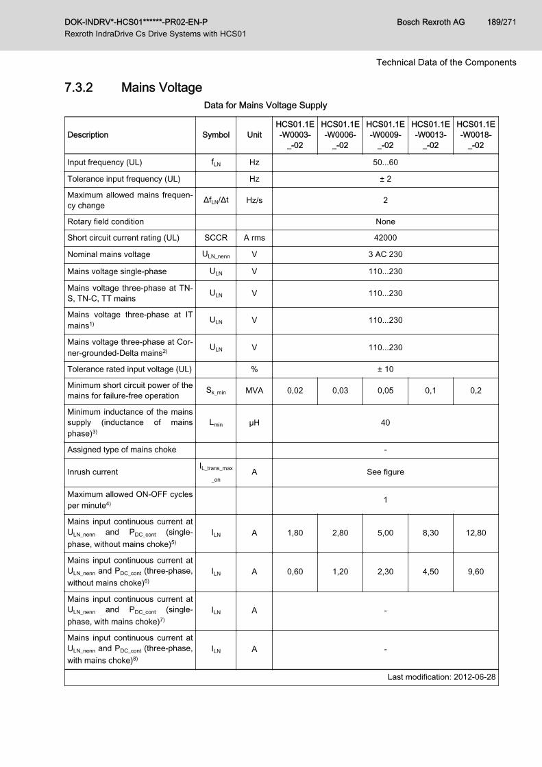
7.3.2 Mains VoltageData for Mains Voltage Supply
Description Symbol UnitHCS01.1E-W0003-
_-02
HCS01.1E-W0006-
_-02
HCS01.1E-W0009-
_-02
HCS01.1E-W0013-
_-02
HCS01.1E-W0018-
_-02
Input frequency (UL) fLN Hz 50...60
Tolerance input frequency (UL) Hz ± 2
Maximum allowed mains frequen‐cy change ΔfLN/Δt Hz/s 2
Rotary field condition None
Short circuit current rating (UL) SCCR A rms 42000
Nominal mains voltage ULN_nenn V 3 AC 230
Mains voltage single-phase ULN V 110...230
Mains voltage three-phase at TN-S, TN-C, TT mains ULN V 110...230
Mains voltage three-phase at ITmains1) ULN V 110...230
Mains voltage three-phase at Cor‐ner-grounded-Delta mains2) ULN V 110...230
Tolerance rated input voltage (UL) % ± 10
Minimum short circuit power of themains for failure-free operation Sk_min MVA 0,02 0,03 0,05 0,1 0,2
Minimum inductance of the mainssupply (inductance of mainsphase)3)
Lmin µH 40
Assigned type of mains choke -
Inrush currentIL_trans_max
_onA See figure
Maximum allowed ON-OFF cyclesper minute4) 1
Mains input continuous current atULN_nenn and PDC_cont (single-phase, without mains choke)5)
ILN A 1,80 2,80 5,00 8,30 12,80
Mains input continuous current atULN_nenn and PDC_cont (three-phase,without mains choke)6)
ILN A 0,60 1,20 2,30 4,50 9,60
Mains input continuous current atULN_nenn and PDC_cont (single-phase, with mains choke)7)
ILN A -
Mains input continuous current atULN_nenn and PDC_cont (three-phase,with mains choke)8)
ILN A -
Last modification: 2012-06-28
DOK-INDRV*-HCS01******-PR02-EN-P Rexroth IndraDrive Cs Drive Systems with HCS01
Bosch Rexroth AG 189/271
Technical Data of the Components
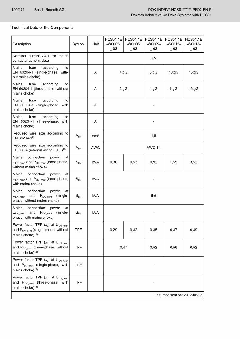
Description Symbol UnitHCS01.1E-W0003-
_-02
HCS01.1E-W0006-
_-02
HCS01.1E-W0009-
_-02
HCS01.1E-W0013-
_-02
HCS01.1E-W0018-
_-02
Nominal current AC1 for mainscontactor at nom. data ILN
Mains fuse according toEN 60204‑1 (single-phase, with‐out mains choke)
A 4;gG 6;gG 10;gG 16;gG
Mains fuse according toEN 60204‑1 (three-phase, withoutmains choke)
A 2;gG 4;gG 6;gG 16;gG
Mains fuse according toEN 60204‑1 (single-phase, withmains choke)
A -
Mains fuse according toEN 60204‑1 (three-phase, withmains choke)
A -
Required wire size according toEN 60204‑19) ALN mm2 1,5
Required wire size according toUL 508 A (internal wiring); (UL)10) ALN AWG AWG 14
Mains connection power atULN_nenn and PDC_cont (three-phase,without mains choke)
SLN kVA 0,30 0,53 0,92 1,55 3,52
Mains connection power atULN_nenn and PDC_cont (three-phase,with mains choke)
SLN kVA -
Mains connection power atULN_nenn and PDC_cont (single-phase, without mains choke)
SLN kVA tbd
Mains connection power atULN_nenn and PDC_cont (single-phase, with mains choke)
SLN kVA -
Power factor TPF (λL) at ULN_nenn
and PDC_cont (single-phase, withoutmains choke)11)
TPF 0,29 0,32 0,35 0,37 0,49
Power factor TPF (λL) at ULN_nenn
and PDC_cont (three-phase, withoutmains choke)12)
TPF 0,47 0,52 0,56 0,52
Power factor TPF (λL) at ULN_nenn
and PDC_cont (single-phase, withmains choke)13)
TPF -
Power factor TPF (λL) at ULN_nenn
and PDC_cont (three-phase, withmains choke)14)
TPF -
Last modification: 2012-06-28
Bosch Rexroth AG DOK-INDRV*-HCS01******-PR02-EN-P Rexroth IndraDrive Cs Drive Systems with HCS01
190/271
Technical Data of the Components
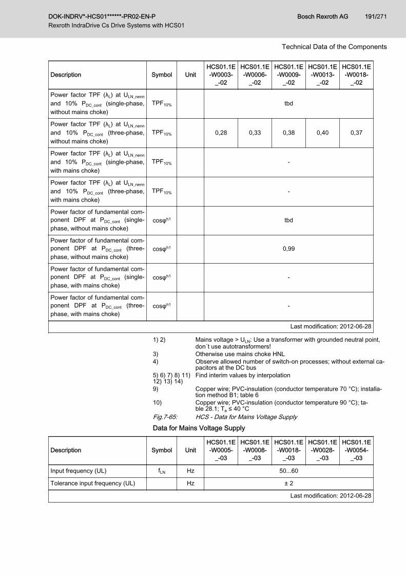
Description Symbol UnitHCS01.1E-W0003-
_-02
HCS01.1E-W0006-
_-02
HCS01.1E-W0009-
_-02
HCS01.1E-W0013-
_-02
HCS01.1E-W0018-
_-02
Power factor TPF (λL) at ULN_nenn
and 10% PDC_cont (single-phase,without mains choke)
TPF10% tbd
Power factor TPF (λL) at ULN_nenn
and 10% PDC_cont (three-phase,without mains choke)
TPF10% 0,28 0,33 0,38 0,40 0,37
Power factor TPF (λL) at ULN_nenn
and 10% PDC_cont (single-phase,with mains choke)
TPF10% -
Power factor TPF (λL) at ULN_nenn
and 10% PDC_cont (three-phase,with mains choke)
TPF10% -
Power factor of fundamental com‐ponent DPF at PDC_cont (single-phase, without mains choke)
cosφh1 tbd
Power factor of fundamental com‐ponent DPF at PDC_cont (three-phase, without mains choke)
cosφh1 0,99
Power factor of fundamental com‐ponent DPF at PDC_cont (single-phase, with mains choke)
cosφh1 -
Power factor of fundamental com‐ponent DPF at PDC_cont (three-phase, with mains choke)
cosφh1 -
Last modification: 2012-06-28
1) 2) Mains voltage > ULN: Use a transformer with grounded neutral point,don´t use autotransformers!
3) Otherwise use mains choke HNL4) Observe allowed number of switch-on processes; without external ca‐
pacitors at the DC bus5) 6) 7) 8) 11)12) 13) 14)
Find interim values by interpolation
9) Copper wire; PVC-insulation (conductor temperature 70 °C); installa‐tion method B1; table 6
10) Copper wire; PVC-insulation (conductor temperature 90 °C); ta‐ble 28.1; Ta ≤ 40 °C
Fig.7-65: HCS - Data for Mains Voltage SupplyData for Mains Voltage Supply
Description Symbol UnitHCS01.1E-W0005-
_-03
HCS01.1E-W0008-
_-03
HCS01.1E-W0018-
_-03
HCS01.1E-W0028-
_-03
HCS01.1E-W0054-
_-03
Input frequency (UL) fLN Hz 50...60
Tolerance input frequency (UL) Hz ± 2
Last modification: 2012-06-28
DOK-INDRV*-HCS01******-PR02-EN-P Rexroth IndraDrive Cs Drive Systems with HCS01
Bosch Rexroth AG 191/271
Technical Data of the Components
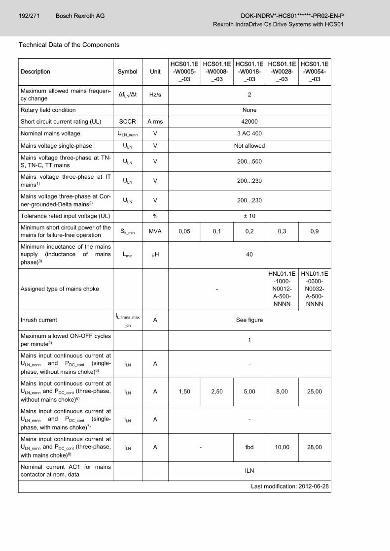
Description Symbol UnitHCS01.1E-W0005-
_-03
HCS01.1E-W0008-
_-03
HCS01.1E-W0018-
_-03
HCS01.1E-W0028-
_-03
HCS01.1E-W0054-
_-03
Maximum allowed mains frequen‐cy change ΔfLN/Δt Hz/s 2
Rotary field condition None
Short circuit current rating (UL) SCCR A rms 42000
Nominal mains voltage ULN_nenn V 3 AC 400
Mains voltage single-phase ULN V Not allowed
Mains voltage three-phase at TN-S, TN-C, TT mains ULN V 200...500
Mains voltage three-phase at ITmains1) ULN V 200...230
Mains voltage three-phase at Cor‐ner-grounded-Delta mains2) ULN V 200...230
Tolerance rated input voltage (UL) % ± 10
Minimum short circuit power of themains for failure-free operation Sk_min MVA 0,05 0,1 0,2 0,3 0,9
Minimum inductance of the mainssupply (inductance of mainsphase)3)
Lmin µH 40
Assigned type of mains choke -
HNL01.1E-1000-N0012-A-500-NNNN
HNL01.1E-0600-N0032-A-500-NNNN
Inrush currentIL_trans_max
_onA See figure
Maximum allowed ON-OFF cyclesper minute4) 1
Mains input continuous current atULN_nenn and PDC_cont (single-phase, without mains choke)5)
ILN A -
Mains input continuous current atULN_nenn and PDC_cont (three-phase,without mains choke)6)
ILN A 1,50 2,50 5,00 8,00 25,00
Mains input continuous current atULN_nenn and PDC_cont (single-phase, with mains choke)7)
ILN A -
Mains input continuous current atULN_nenn and PDC_cont (three-phase,with mains choke)8)
ILN A - tbd 10,00 28,00
Nominal current AC1 for mainscontactor at nom. data ILN
Last modification: 2012-06-28
Bosch Rexroth AG DOK-INDRV*-HCS01******-PR02-EN-P Rexroth IndraDrive Cs Drive Systems with HCS01
192/271
Technical Data of the Components
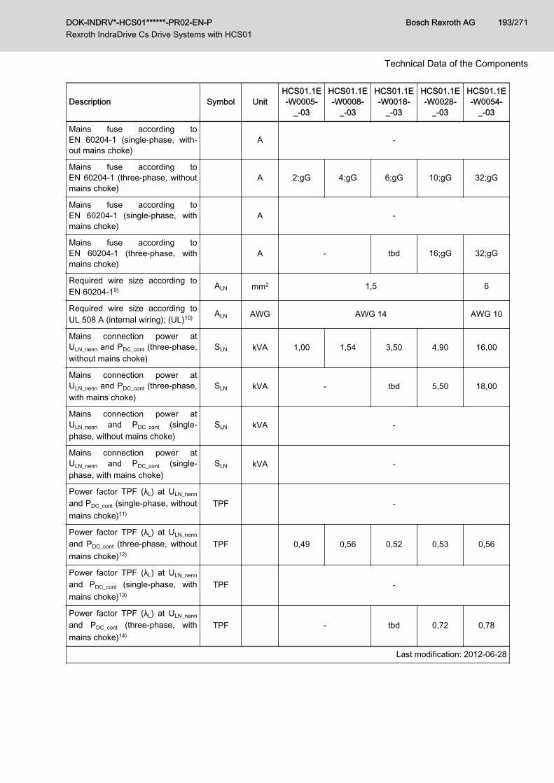
Description Symbol UnitHCS01.1E-W0005-
_-03
HCS01.1E-W0008-
_-03
HCS01.1E-W0018-
_-03
HCS01.1E-W0028-
_-03
HCS01.1E-W0054-
_-03
Mains fuse according toEN 60204‑1 (single-phase, with‐out mains choke)
A -
Mains fuse according toEN 60204‑1 (three-phase, withoutmains choke)
A 2;gG 4;gG 6;gG 10;gG 32;gG
Mains fuse according toEN 60204‑1 (single-phase, withmains choke)
A -
Mains fuse according toEN 60204‑1 (three-phase, withmains choke)
A - tbd 16;gG 32;gG
Required wire size according toEN 60204‑19) ALN mm2 1,5 6
Required wire size according toUL 508 A (internal wiring); (UL)10) ALN AWG AWG 14 AWG 10
Mains connection power atULN_nenn and PDC_cont (three-phase,without mains choke)
SLN kVA 1,00 1,54 3,50 4,90 16,00
Mains connection power atULN_nenn and PDC_cont (three-phase,with mains choke)
SLN kVA - tbd 5,50 18,00
Mains connection power atULN_nenn and PDC_cont (single-phase, without mains choke)
SLN kVA -
Mains connection power atULN_nenn and PDC_cont (single-phase, with mains choke)
SLN kVA -
Power factor TPF (λL) at ULN_nenn
and PDC_cont (single-phase, withoutmains choke)11)
TPF -
Power factor TPF (λL) at ULN_nenn
and PDC_cont (three-phase, withoutmains choke)12)
TPF 0,49 0,56 0,52 0,53 0,56
Power factor TPF (λL) at ULN_nenn
and PDC_cont (single-phase, withmains choke)13)
TPF -
Power factor TPF (λL) at ULN_nenn
and PDC_cont (three-phase, withmains choke)14)
TPF - tbd 0,72 0,78
Last modification: 2012-06-28
DOK-INDRV*-HCS01******-PR02-EN-P Rexroth IndraDrive Cs Drive Systems with HCS01
Bosch Rexroth AG 193/271
Technical Data of the Components
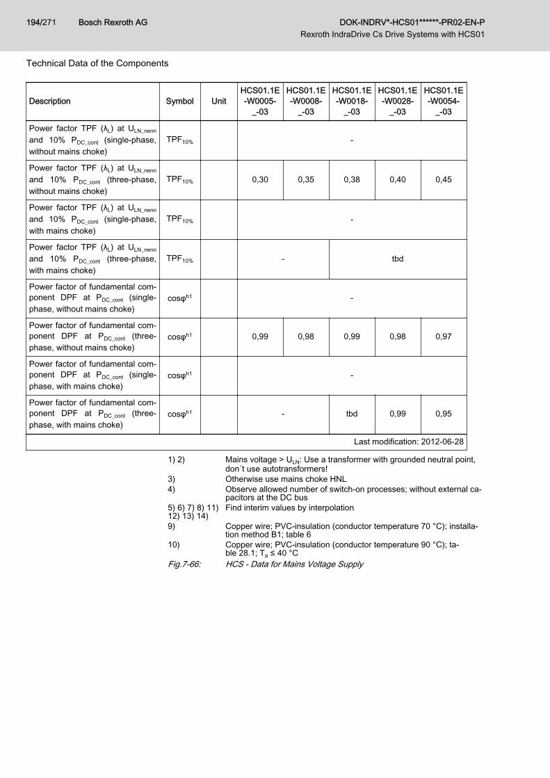
Description Symbol UnitHCS01.1E-W0005-
_-03
HCS01.1E-W0008-
_-03
HCS01.1E-W0018-
_-03
HCS01.1E-W0028-
_-03
HCS01.1E-W0054-
_-03
Power factor TPF (λL) at ULN_nenn
and 10% PDC_cont (single-phase,without mains choke)
TPF10% -
Power factor TPF (λL) at ULN_nenn
and 10% PDC_cont (three-phase,without mains choke)
TPF10% 0,30 0,35 0,38 0,40 0,45
Power factor TPF (λL) at ULN_nenn
and 10% PDC_cont (single-phase,with mains choke)
TPF10% -
Power factor TPF (λL) at ULN_nenn
and 10% PDC_cont (three-phase,with mains choke)
TPF10% - tbd
Power factor of fundamental com‐ponent DPF at PDC_cont (single-phase, without mains choke)
cosφh1 -
Power factor of fundamental com‐ponent DPF at PDC_cont (three-phase, without mains choke)
cosφh1 0,99 0,98 0,99 0,98 0,97
Power factor of fundamental com‐ponent DPF at PDC_cont (single-phase, with mains choke)
cosφh1 -
Power factor of fundamental com‐ponent DPF at PDC_cont (three-phase, with mains choke)
cosφh1 - tbd 0,99 0,95
Last modification: 2012-06-28
1) 2) Mains voltage > ULN: Use a transformer with grounded neutral point,don´t use autotransformers!
3) Otherwise use mains choke HNL4) Observe allowed number of switch-on processes; without external ca‐
pacitors at the DC bus5) 6) 7) 8) 11)12) 13) 14)
Find interim values by interpolation
9) Copper wire; PVC-insulation (conductor temperature 70 °C); installa‐tion method B1; table 6
10) Copper wire; PVC-insulation (conductor temperature 90 °C); ta‐ble 28.1; Ta ≤ 40 °C
Fig.7-66: HCS - Data for Mains Voltage Supply
Bosch Rexroth AG DOK-INDRV*-HCS01******-PR02-EN-P Rexroth IndraDrive Cs Drive Systems with HCS01
194/271
Technical Data of the Components
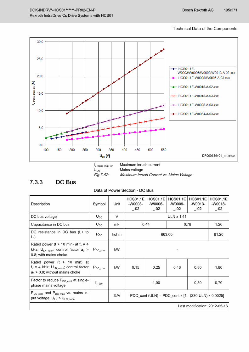
IL_trans_max_on Maximum inrush currentULN Mains voltageFig.7-67: Maximum Inrush Current vs. Mains Voltage
7.3.3 DC BusData of Power Section - DC Bus
Description Symbol UnitHCS01.1E-W0003-
_-02
HCS01.1E-W0006-
_-02
HCS01.1E-W0009-
_-02
HCS01.1E-W0013-
_-02
HCS01.1E-W0018-
_-02
DC bus voltage UDC V ULN x 1,41
Capacitance in DC bus CDC mF 0,44 0,78 1,20
DC resistance in DC bus (L+ toL-) RDC kohm 663,00 61,20
Rated power (t > 10 min) at fs = 4kHz; ULN_nenn; control factor a0 >0.8; with mains choke
PDC_cont kW -
Rated power (t > 10 min) atfs = 4 kHz; ULN_nenn; control factora0 > 0.8; without mains choke
PDC_cont kW 0,15 0,25 0,46 0,80 1,80
Factor to reduce PDC_cont at single-phase mains voltage
f1_3ph 1,00 0,80 0,70
PDC_cont and PDC_max vs. mains in‐put voltage; ULN ≤ ULN_nenn
%/V PDC_cont (ULN) = PDC_cont x [1 - (230-ULN) x 0,0025]
Last modification: 2012-05-16
DOK-INDRV*-HCS01******-PR02-EN-P Rexroth IndraDrive Cs Drive Systems with HCS01
Bosch Rexroth AG 195/271
Technical Data of the Components
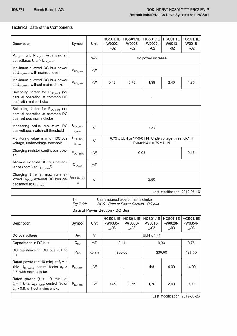
Description Symbol UnitHCS01.1E-W0003-
_-02
HCS01.1E-W0006-
_-02
HCS01.1E-W0009-
_-02
HCS01.1E-W0013-
_-02
HCS01.1E-W0018-
_-02
PDC_cont and PDC_max vs. mains in‐put voltage; ULN > ULN_nenn
%/V No power increase
Maximum allowed DC bus powerat ULN_nenn; with mains choke PDC_max kW -
Maximum allowed DC bus powerat ULN_nenn; without mains choke PDC_max kW 0,45 0,75 1,38 2,40 4,80
Balancing factor for PDC_cont (forparallel operation at common DCbus) with mains choke
-
Balancing factor for PDC_cont (forparallel operation at common DCbus) without mains choke
-
Monitoring value maximum DCbus voltage, switch-off threshold
UDC_lim‐
it_maxV 420
Monitoring value minimum DC busvoltage, undervoltage threshold
UDC_lim‐
it_minV 0.75 x ULN or "P-0-0114, Undervoltage threshold", if
P-0-0114 > 0.75 x ULN
Charging resistor continuous pow‐er PDC_Start kW 0,03 0,15
Allowed external DC bus capaci‐tance (nom.) at ULN_nenn
1) CDCext mF -
Charging time at maximum al‐lowed CDCext external DC bus ca‐pacitance at ULN_nenn
tlade_DC_Ce
xts 2,50
Last modification: 2012-05-16
1) Use assigned type of mains chokeFig.7-68: HCS - Data of Power Section - DC busData of Power Section - DC Bus
Description Symbol UnitHCS01.1E-W0005-
_-03
HCS01.1E-W0008-
_-03
HCS01.1E-W0018-
_-03
HCS01.1E-W0028-
_-03
HCS01.1E-W0054-
_-03
DC bus voltage UDC V ULN x 1,41
Capacitance in DC bus CDC mF 0,11 0,33 0,78
DC resistance in DC bus (L+ toL-) RDC kohm 320,00 230,00 136,00
Rated power (t > 10 min) at fs = 4kHz; ULN_nenn; control factor a0 >0.8; with mains choke
PDC_cont kW - tbd 4,00 14,00
Rated power (t > 10 min) atfs = 4 kHz; ULN_nenn; control factora0 > 0.8; without mains choke
PDC_cont kW 0,46 0,86 1,70 2,60 9,00
Last modification: 2012-06-26
Bosch Rexroth AG DOK-INDRV*-HCS01******-PR02-EN-P Rexroth IndraDrive Cs Drive Systems with HCS01
196/271
Technical Data of the Components
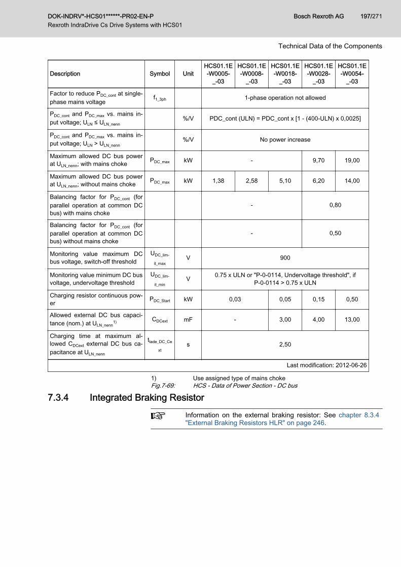
Description Symbol UnitHCS01.1E-W0005-
_-03
HCS01.1E-W0008-
_-03
HCS01.1E-W0018-
_-03
HCS01.1E-W0028-
_-03
HCS01.1E-W0054-
_-03
Factor to reduce PDC_cont at single-phase mains voltage
f1_3ph 1-phase operation not allowed
PDC_cont and PDC_max vs. mains in‐put voltage; ULN ≤ ULN_nenn
%/V PDC_cont (ULN) = PDC_cont x [1 - (400-ULN) x 0,0025]
PDC_cont and PDC_max vs. mains in‐put voltage; ULN > ULN_nenn
%/V No power increase
Maximum allowed DC bus powerat ULN_nenn; with mains choke PDC_max kW - 9,70 19,00
Maximum allowed DC bus powerat ULN_nenn; without mains choke PDC_max kW 1,38 2,58 5,10 6,20 14,00
Balancing factor for PDC_cont (forparallel operation at common DCbus) with mains choke
- 0,80
Balancing factor for PDC_cont (forparallel operation at common DCbus) without mains choke
- 0,50
Monitoring value maximum DCbus voltage, switch-off threshold
UDC_lim‐
it_maxV 900
Monitoring value minimum DC busvoltage, undervoltage threshold
UDC_lim‐
it_minV 0.75 x ULN or "P-0-0114, Undervoltage threshold", if
P-0-0114 > 0.75 x ULN
Charging resistor continuous pow‐er PDC_Start kW 0,03 0,05 0,15 0,50
Allowed external DC bus capaci‐tance (nom.) at ULN_nenn
1) CDCext mF - 3,00 4,00 13,00
Charging time at maximum al‐lowed CDCext external DC bus ca‐pacitance at ULN_nenn
tlade_DC_Ce
xts 2,50
Last modification: 2012-06-26
1) Use assigned type of mains chokeFig.7-69: HCS - Data of Power Section - DC bus
7.3.4 Integrated Braking Resistor
Information on the external braking resistor: See chapter 8.3.4 "External Braking Resistors HLR" on page 246.
DOK-INDRV*-HCS01******-PR02-EN-P Rexroth IndraDrive Cs Drive Systems with HCS01
Bosch Rexroth AG 197/271
Technical Data of the Components
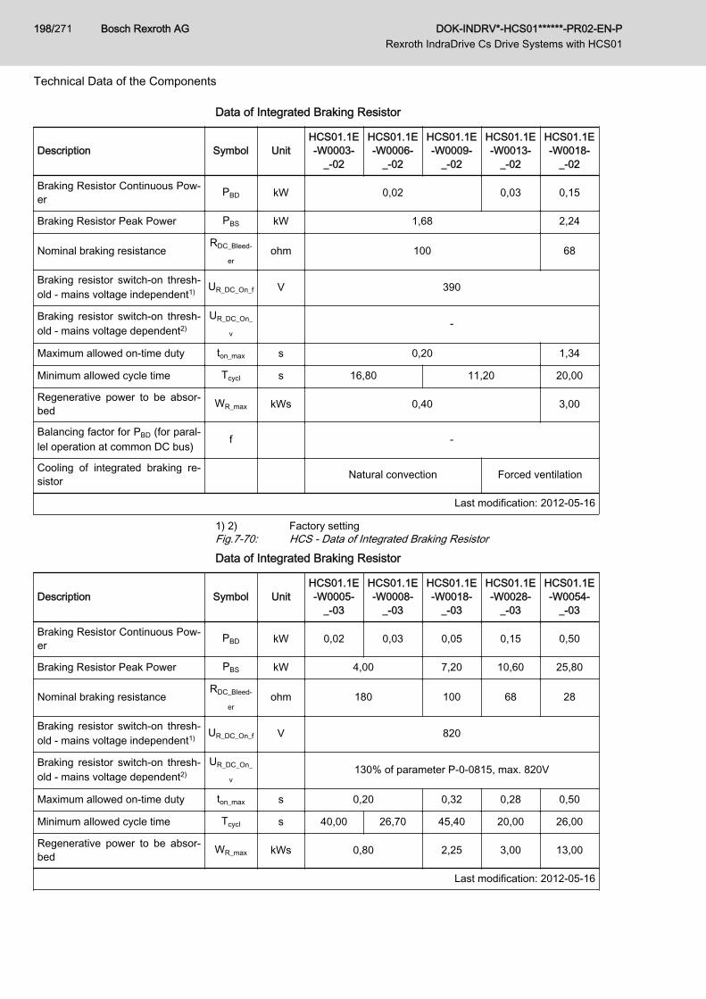
Data of Integrated Braking Resistor
Description Symbol UnitHCS01.1E-W0003-
_-02
HCS01.1E-W0006-
_-02
HCS01.1E-W0009-
_-02
HCS01.1E-W0013-
_-02
HCS01.1E-W0018-
_-02
Braking Resistor Continuous Pow‐er PBD kW 0,02 0,03 0,15
Braking Resistor Peak Power PBS kW 1,68 2,24
Nominal braking resistanceRDC_Bleed‐
erohm 100 68
Braking resistor switch-on thresh‐old - mains voltage independent1) UR_DC_On_f V 390
Braking resistor switch-on thresh‐old - mains voltage dependent2)
UR_DC_On_
v-
Maximum allowed on-time duty ton_max s 0,20 1,34
Minimum allowed cycle time Tcycl s 16,80 11,20 20,00
Regenerative power to be absor‐bed WR_max kWs 0,40 3,00
Balancing factor for PBD (for paral‐lel operation at common DC bus) f -
Cooling of integrated braking re‐sistor Natural convection Forced ventilation
Last modification: 2012-05-16
1) 2) Factory settingFig.7-70: HCS - Data of Integrated Braking ResistorData of Integrated Braking Resistor
Description Symbol UnitHCS01.1E-W0005-
_-03
HCS01.1E-W0008-
_-03
HCS01.1E-W0018-
_-03
HCS01.1E-W0028-
_-03
HCS01.1E-W0054-
_-03
Braking Resistor Continuous Pow‐er PBD kW 0,02 0,03 0,05 0,15 0,50
Braking Resistor Peak Power PBS kW 4,00 7,20 10,60 25,80
Nominal braking resistanceRDC_Bleed‐
erohm 180 100 68 28
Braking resistor switch-on thresh‐old - mains voltage independent1) UR_DC_On_f V 820
Braking resistor switch-on thresh‐old - mains voltage dependent2)
UR_DC_On_
v130% of parameter P-0-0815, max. 820V
Maximum allowed on-time duty ton_max s 0,20 0,32 0,28 0,50
Minimum allowed cycle time Tcycl s 40,00 26,70 45,40 20,00 26,00
Regenerative power to be absor‐bed WR_max kWs 0,80 2,25 3,00 13,00
Last modification: 2012-05-16
Bosch Rexroth AG DOK-INDRV*-HCS01******-PR02-EN-P Rexroth IndraDrive Cs Drive Systems with HCS01
198/271
Technical Data of the Components
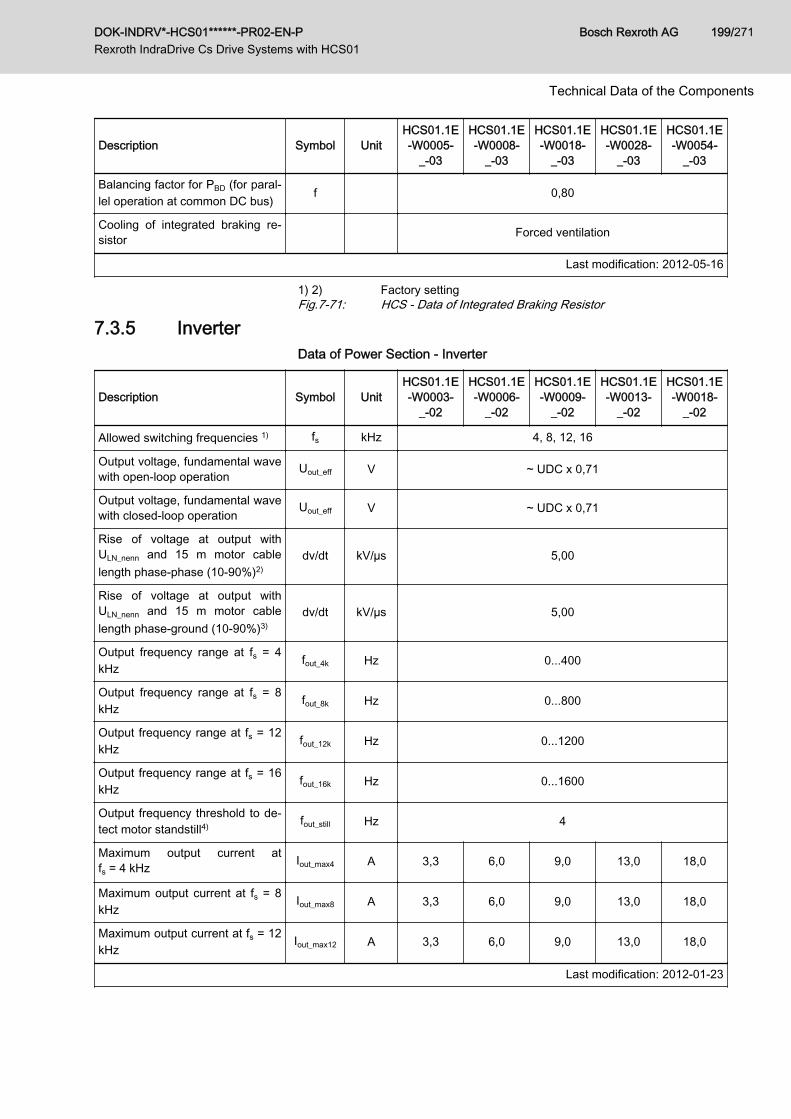
Description Symbol UnitHCS01.1E-W0005-
_-03
HCS01.1E-W0008-
_-03
HCS01.1E-W0018-
_-03
HCS01.1E-W0028-
_-03
HCS01.1E-W0054-
_-03
Balancing factor for PBD (for paral‐lel operation at common DC bus) f 0,80
Cooling of integrated braking re‐sistor Forced ventilation
Last modification: 2012-05-16
1) 2) Factory settingFig.7-71: HCS - Data of Integrated Braking Resistor
7.3.5 InverterData of Power Section - Inverter
Description Symbol UnitHCS01.1E-W0003-
_-02
HCS01.1E-W0006-
_-02
HCS01.1E-W0009-
_-02
HCS01.1E-W0013-
_-02
HCS01.1E-W0018-
_-02
Allowed switching frequencies 1) fs kHz 4, 8, 12, 16
Output voltage, fundamental wavewith open-loop operation Uout_eff V ~ UDC x 0,71
Output voltage, fundamental wavewith closed-loop operation Uout_eff V ~ UDC x 0,71
Rise of voltage at output withULN_nenn and 15 m motor cablelength phase-phase (10‑90%)2)
dv/dt kV/µs 5,00
Rise of voltage at output withULN_nenn and 15 m motor cablelength phase-ground (10‑90%)3)
dv/dt kV/µs 5,00
Output frequency range at fs = 4kHz
fout_4k Hz 0...400
Output frequency range at fs = 8kHz
fout_8k Hz 0...800
Output frequency range at fs = 12kHz
fout_12k Hz 0...1200
Output frequency range at fs = 16kHz
fout_16k Hz 0...1600
Output frequency threshold to de‐tect motor standstill4) fout_still Hz 4
Maximum output current atfs = 4 kHz Iout_max4 A 3,3 6,0 9,0 13,0 18,0
Maximum output current at fs = 8kHz
Iout_max8 A 3,3 6,0 9,0 13,0 18,0
Maximum output current at fs = 12kHz
Iout_max12 A 3,3 6,0 9,0 13,0 18,0
Last modification: 2012-01-23
DOK-INDRV*-HCS01******-PR02-EN-P Rexroth IndraDrive Cs Drive Systems with HCS01
Bosch Rexroth AG 199/271
Technical Data of the Components
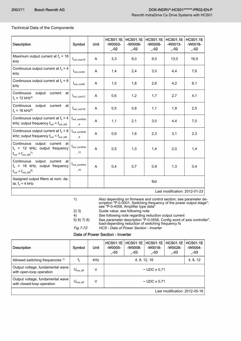
Description Symbol UnitHCS01.1E-W0003-
_-02
HCS01.1E-W0006-
_-02
HCS01.1E-W0009-
_-02
HCS01.1E-W0013-
_-02
HCS01.1E-W0018-
_-02
Maximum output current at fs = 16kHz
Iout_max16 A 3,3 6,0 9,0 13,0 16,5
Continuous output current at fs = 4kHz
Iout_cont4 A 1,4 2,4 3,0 4,4 7,6
Continuous output current at fs = 8kHz
Iout_cont8 A 1,0 1,8 2,6 4,2 6,1
Continuous output current atfs = 12 kHz5) Iout_cont12 A 0,6 1,2 1,7 2,7 4,1
Continuous output current atfs = 16 kHz6) Iout_cont16 A 0,5 0,8 1,1 1,9 2,5
Continuous output current at fs = 4kHz; output frequency fout < fout_still
Iout_cont0Hz
_4A 1,1 2,1 3,0 4,4 7,0
Continuous output current at fs = 8kHz; output frequency fout < fout_still
Iout_cont0Hz
_8A 0,9 1,6 2,3 3,1 2,3
Continuous output current atfs = 12 kHz; output frequencyfout < fout_still
7)
Iout_cont0Hz
_12A 0,5 1,0 1,4 2,0 1,4
Continuous output current atfs = 16 kHz; output frequencyfout < fout_still
8)
Iout_cont0Hz
_16A 0,4 0,7 0,9 1,3 0,4
Assigned output filters at nom. da‐ta; fs = 4 kHz tbd
Last modification: 2012-01-23
1) Also depending on firmware and control section; see parameter de‐scription "P‑0‑0001, Switching frequency of the power output stage";see "P‑0‑4058, Amplifier type data"
2) 3) Guide value, see following note4) See following note regarding reduction output current5) 6) 7) 8) See parameter description "P‑0‑0556, Config word of axis controller",
load-depending reduction of switching frequency fsFig.7-72: HCS - Data of Power Section - InverterData of Power Section - Inverter
Description Symbol UnitHCS01.1E-W0005-
_-03
HCS01.1E-W0008-
_-03
HCS01.1E-W0018-
_-03
HCS01.1E-W0028-
_-03
HCS01.1E-W0054-
_-03
Allowed switching frequencies 1) fs kHz 4, 8, 12, 16 4, 8, 12
Output voltage, fundamental wavewith open-loop operation Uout_eff V ~ UDC x 0,71
Output voltage, fundamental wavewith closed-loop operation Uout_eff V ~ UDC x 0,71
Last modification: 2012-05-16
Bosch Rexroth AG DOK-INDRV*-HCS01******-PR02-EN-P Rexroth IndraDrive Cs Drive Systems with HCS01
200/271
Technical Data of the Components
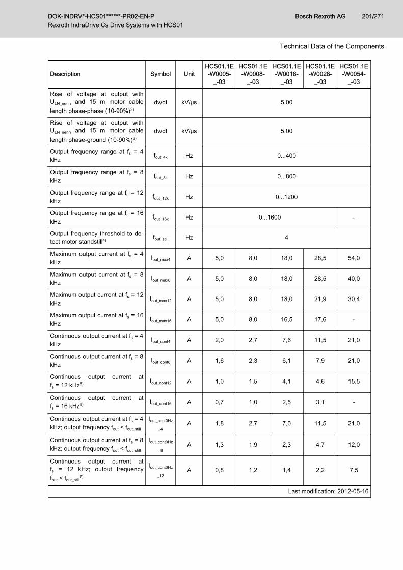
Description Symbol UnitHCS01.1E-W0005-
_-03
HCS01.1E-W0008-
_-03
HCS01.1E-W0018-
_-03
HCS01.1E-W0028-
_-03
HCS01.1E-W0054-
_-03
Rise of voltage at output withULN_nenn and 15 m motor cablelength phase-phase (10‑90%)2)
dv/dt kV/µs 5,00
Rise of voltage at output withULN_nenn and 15 m motor cablelength phase-ground (10‑90%)3)
dv/dt kV/µs 5,00
Output frequency range at fs = 4kHz
fout_4k Hz 0...400
Output frequency range at fs = 8kHz
fout_8k Hz 0...800
Output frequency range at fs = 12kHz
fout_12k Hz 0...1200
Output frequency range at fs = 16kHz
fout_16k Hz 0...1600 -
Output frequency threshold to de‐tect motor standstill4) fout_still Hz 4
Maximum output current at fs = 4kHz
Iout_max4 A 5,0 8,0 18,0 28,5 54,0
Maximum output current at fs = 8kHz
Iout_max8 A 5,0 8,0 18,0 28,5 40,0
Maximum output current at fs = 12kHz
Iout_max12 A 5,0 8,0 18,0 21,9 30,4
Maximum output current at fs = 16kHz
Iout_max16 A 5,0 8,0 16,5 17,6 -
Continuous output current at fs = 4kHz
Iout_cont4 A 2,0 2,7 7,6 11,5 21,0
Continuous output current at fs = 8kHz
Iout_cont8 A 1,6 2,3 6,1 7,9 21,0
Continuous output current atfs = 12 kHz5) Iout_cont12 A 1,0 1,5 4,1 4,6 15,5
Continuous output current atfs = 16 kHz6) Iout_cont16 A 0,7 1,0 2,5 3,1 -
Continuous output current at fs = 4kHz; output frequency fout < fout_still
Iout_cont0Hz
_4A 1,8 2,7 7,0 11,5 21,0
Continuous output current at fs = 8kHz; output frequency fout < fout_still
Iout_cont0Hz
_8A 1,3 1,9 2,3 4,7 12,0
Continuous output current atfs = 12 kHz; output frequencyfout < fout_still
7)
Iout_cont0Hz
_12A 0,8 1,2 1,4 2,2 7,5
Last modification: 2012-05-16
DOK-INDRV*-HCS01******-PR02-EN-P Rexroth IndraDrive Cs Drive Systems with HCS01
Bosch Rexroth AG 201/271
Technical Data of the Components
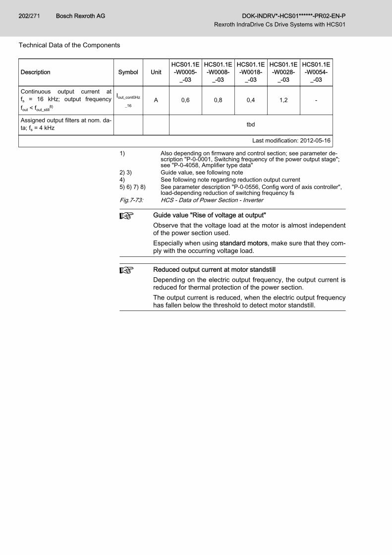
Description Symbol UnitHCS01.1E-W0005-
_-03
HCS01.1E-W0008-
_-03
HCS01.1E-W0018-
_-03
HCS01.1E-W0028-
_-03
HCS01.1E-W0054-
_-03
Continuous output current atfs = 16 kHz; output frequencyfout < fout_still
8)
Iout_cont0Hz
_16A 0,6 0,8 0,4 1,2 -
Assigned output filters at nom. da‐ta; fs = 4 kHz tbd
Last modification: 2012-05-16
1) Also depending on firmware and control section; see parameter de‐scription "P‑0‑0001, Switching frequency of the power output stage";see "P‑0‑4058, Amplifier type data"
2) 3) Guide value, see following note4) See following note regarding reduction output current5) 6) 7) 8) See parameter description "P‑0‑0556, Config word of axis controller",
load-depending reduction of switching frequency fsFig.7-73: HCS - Data of Power Section - Inverter
Guide value "Rise of voltage at output"Observe that the voltage load at the motor is almost independentof the power section used.Especially when using standard motors, make sure that they com‐ply with the occurring voltage load.
Reduced output current at motor standstillDepending on the electric output frequency, the output current isreduced for thermal protection of the power section.The output current is reduced, when the electric output frequencyhas fallen below the threshold to detect motor standstill.
Bosch Rexroth AG DOK-INDRV*-HCS01******-PR02-EN-P Rexroth IndraDrive Cs Drive Systems with HCS01
202/271
Technical Data of the Components

8 Cables, Accessories, Additional Components8.1 Overview8.1.1 Cables
Motor power cables See documentation "Rexroth Connection Cables IndraDrive and IndraDyn"
Encoder cables ● RKG0033 (MSM motor)● RKG0034 (MSM motor, extension)● RKG0035 (1Vpp Heidenhain standard)
● RKG0036 (EnDat, SSI)● RKG0041 (incl. D-Sub connector RGS0001/K01; MSM motor)● RKG4200 (HIPERFACE®)See also index entry "Cables → Encoder cables"
Multi-Ethernet cables ● RKB0011(To connect the drive system to the higher-level control unit)
● RKB0013(To connect devices arranged side by side)
See also index entry "Cables → RKB0011" and "Cables → RKB0013"
Fig.8-1: Cables - Overview
8.1.2 Accessories
Accessories Note
Mounting and connection accessories (HAS09)● Screws for mounting the component● Screws for connecting the equipment grounding conductor● Parts for shield connection and strain relief of cables (plates, screws, clips)● Adhesive labels with notes on safety in the English and French languages
Standard sup‐ply
DC bus connector (RLS0778/K06)Connector for connecting● the DC buses of several HCS01.1E-W00xx-x-03 drive controllers● an HCS01.1E-W00xx-x-03 drive controller to an HLC01.2 DC bus capacitor unit
To be orderedseparately
Battery box (SUP-E01-MSM-BATTERYBOX)Accessory for operating MSM motors with absolute value encoder
To be orderedseparately
Replacement battery (SUP-E03-DKC*CS-BATTRY)Replacement battery for SUP-E01-MSM-BATTERYBOX
To be orderedseparately
Encoder cable (RKG0041)Accessory for operating MSM motors with absolute value encoder
To be orderedseparately
DOK-INDRV*-HCS01******-PR02-EN-P Rexroth IndraDrive Cs Drive Systems with HCS01
Bosch Rexroth AG 203/271
Cables, Accessories, Additional Components
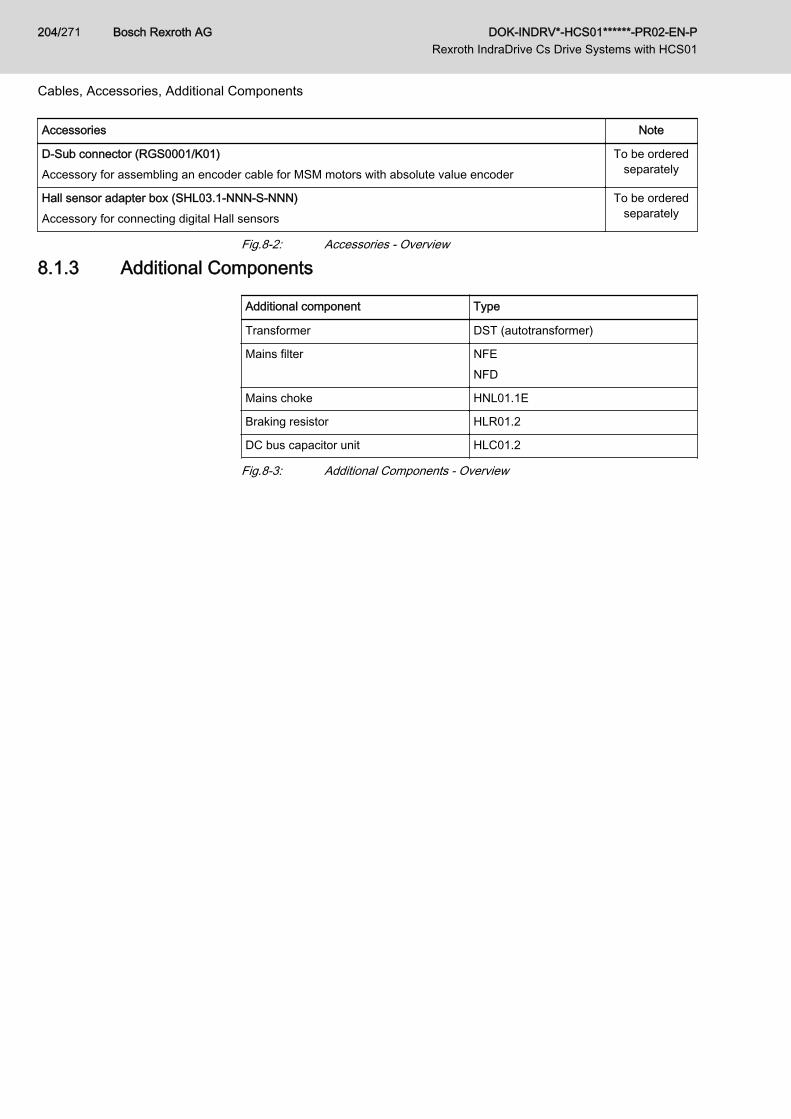
Accessories Note
D-Sub connector (RGS0001/K01)Accessory for assembling an encoder cable for MSM motors with absolute value encoder
To be orderedseparately
Hall sensor adapter box (SHL03.1-NNN-S-NNN)Accessory for connecting digital Hall sensors
To be orderedseparately
Fig.8-2: Accessories - Overview
8.1.3 Additional Components
Additional component Type
Transformer DST (autotransformer)
Mains filter NFENFD
Mains choke HNL01.1E
Braking resistor HLR01.2
DC bus capacitor unit HLC01.2
Fig.8-3: Additional Components - Overview
Bosch Rexroth AG DOK-INDRV*-HCS01******-PR02-EN-P Rexroth IndraDrive Cs Drive Systems with HCS01
204/271
Cables, Accessories, Additional Components

8.2 Accessories8.2.1 Mounting and Connection Accessories (HAS09)
Use The accessories contain:● Screws for mounting the component● Screws for connecting the equipment grounding conductor● Parts for shield connection of cables (plates, screws)● Adhesive labels with notes on safety in the English and French languag‐
es. Place the adhesive labels clearly visibly at the component or in theimmediate vicinity of the component, if the adhesive labels existing atthe component are hidden by neighboring components.
Assignment
Accessories Component
HAS09.1-001-NNN-NN HCS01.1E-W0003 … W0028
HAS09.1-003-NNN-NN HCS01.1E-W0054
HAS09.1-004-NNN-NN HLC01.2; HLR01.2N
Fig.8-4: HAS09 and HCS01
DOK-INDRV*-HCS01******-PR02-EN-P Rexroth IndraDrive Cs Drive Systems with HCS01
Bosch Rexroth AG 205/271
Cables, Accessories, Additional Components
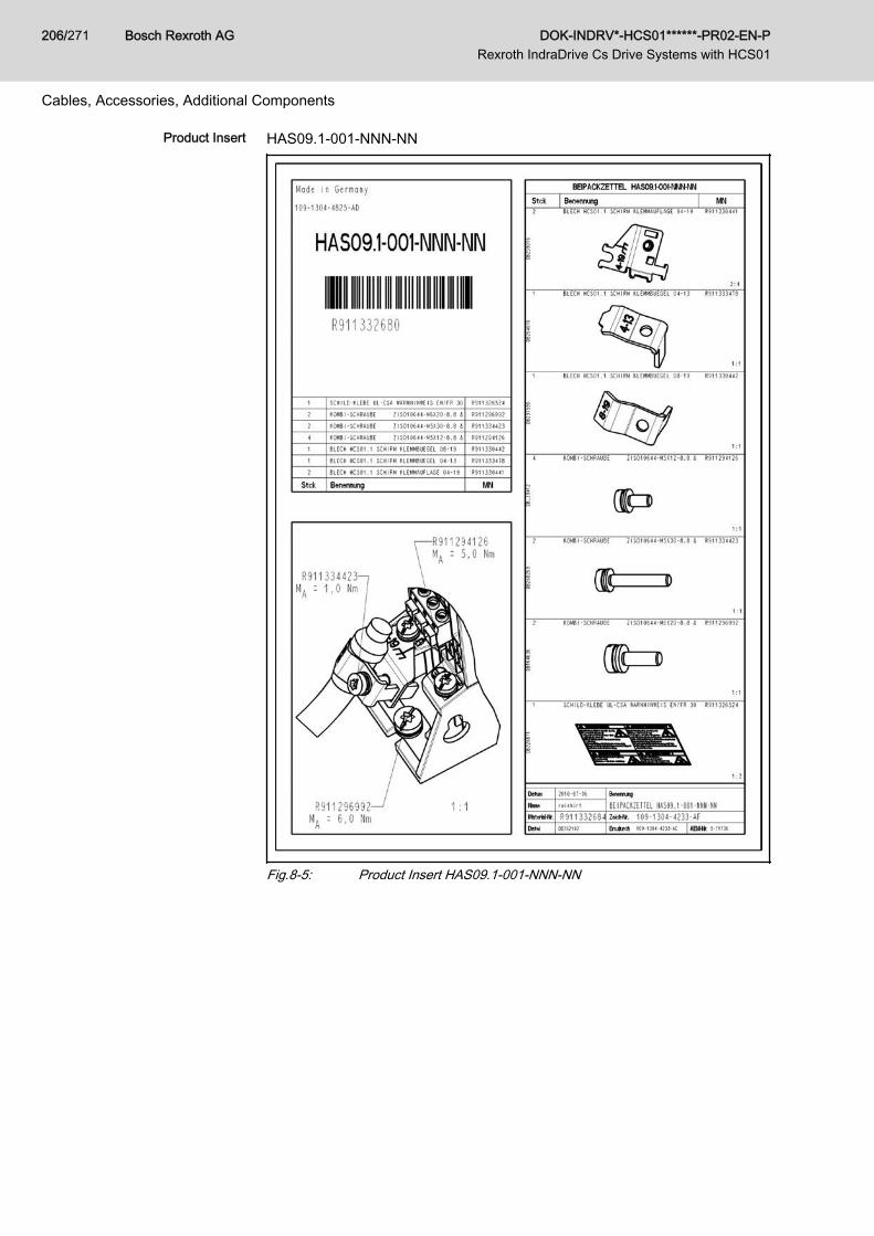
Product Insert HAS09.1-001-NNN-NN
Fig.8-5: Product Insert HAS09.1-001-NNN-NN
Bosch Rexroth AG DOK-INDRV*-HCS01******-PR02-EN-P Rexroth IndraDrive Cs Drive Systems with HCS01
206/271
Cables, Accessories, Additional Components
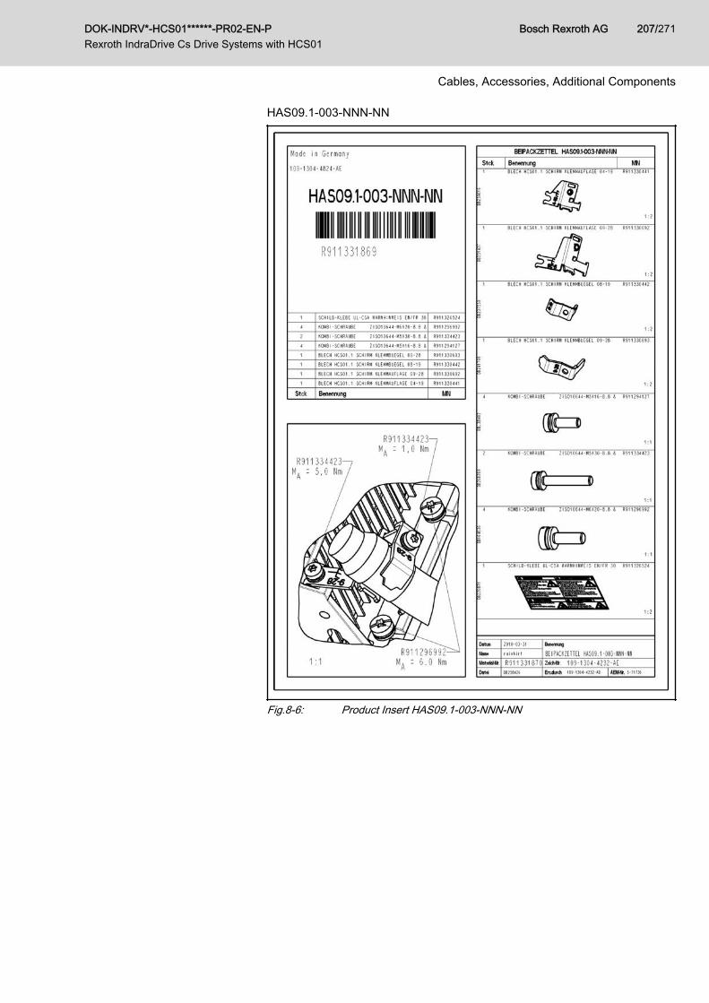
HAS09.1-003-NNN-NN
Fig.8-6: Product Insert HAS09.1-003-NNN-NN
DOK-INDRV*-HCS01******-PR02-EN-P Rexroth IndraDrive Cs Drive Systems with HCS01
Bosch Rexroth AG 207/271
Cables, Accessories, Additional Components
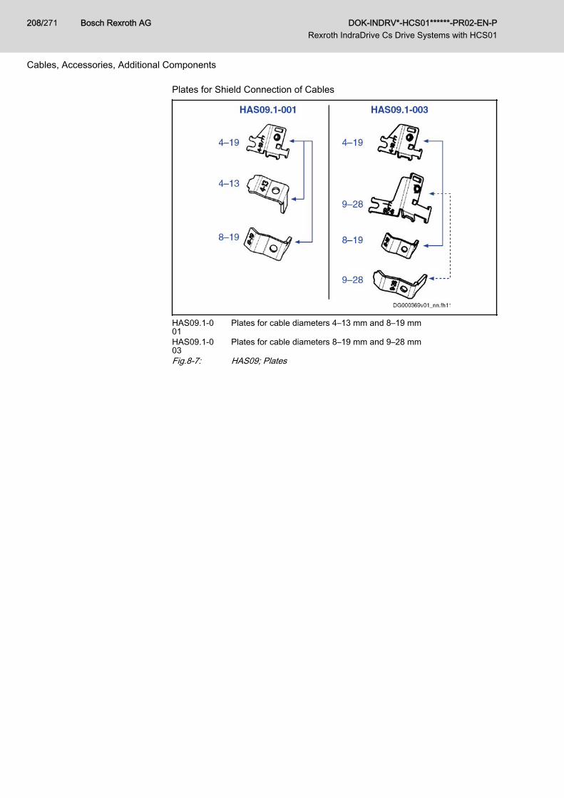
Plates for Shield Connection of Cables
HAS09.1-001
Plates for cable diameters 4–13 mm and 8–19 mm
HAS09.1-003
Plates for cable diameters 8–19 mm and 9–28 mm
Fig.8-7: HAS09; Plates
Bosch Rexroth AG DOK-INDRV*-HCS01******-PR02-EN-P Rexroth IndraDrive Cs Drive Systems with HCS01
208/271
Cables, Accessories, Additional Components
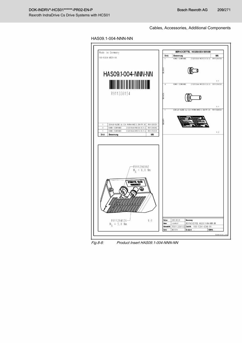
HAS09.1-004-NNN-NN
Fig.8-8: Product Insert HAS09.1-004-NNN-NN
DOK-INDRV*-HCS01******-PR02-EN-P Rexroth IndraDrive Cs Drive Systems with HCS01
Bosch Rexroth AG 209/271
Cables, Accessories, Additional Components
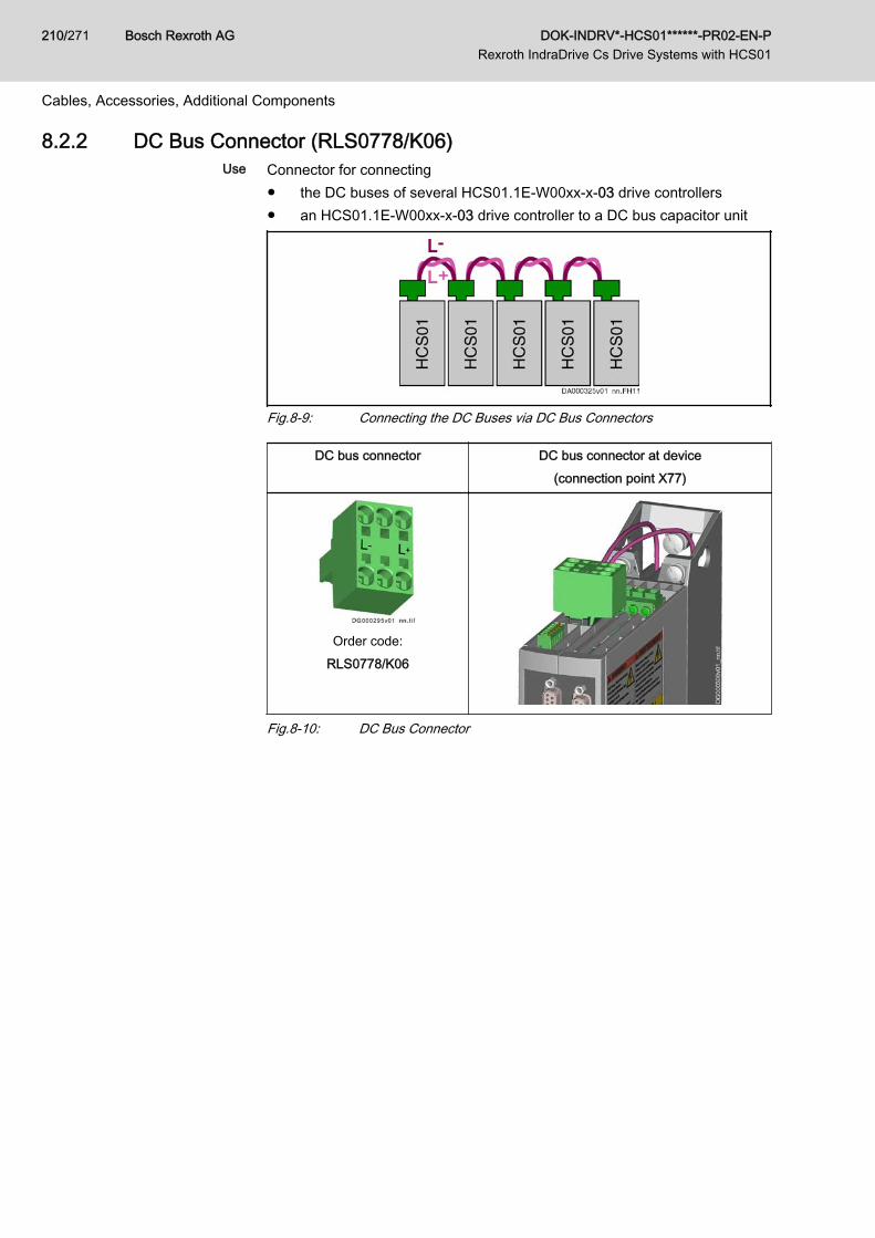
8.2.2 DC Bus Connector (RLS0778/K06)Use Connector for connecting
● the DC buses of several HCS01.1E-W00xx-x-03 drive controllers● an HCS01.1E-W00xx-x-03 drive controller to a DC bus capacitor unit
Fig.8-9: Connecting the DC Buses via DC Bus Connectors
DC bus connector DC bus connector at device(connection point X77)
Order code:RLS0778/K06
Fig.8-10: DC Bus Connector
Bosch Rexroth AG DOK-INDRV*-HCS01******-PR02-EN-P Rexroth IndraDrive Cs Drive Systems with HCS01
210/271
Cables, Accessories, Additional Components
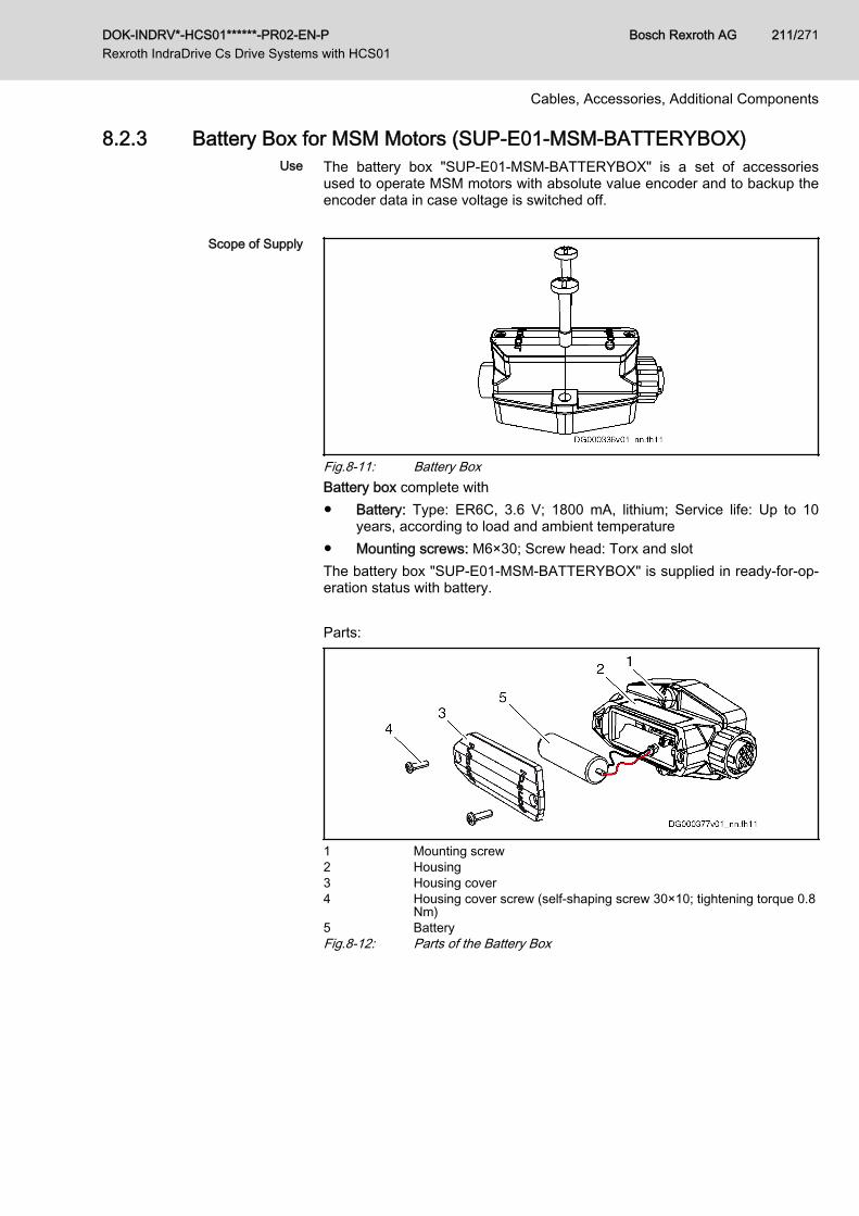
8.2.3 Battery Box for MSM Motors (SUP-E01-MSM-BATTERYBOX)Use The battery box "SUP-E01-MSM-BATTERYBOX" is a set of accessories
used to operate MSM motors with absolute value encoder and to backup theencoder data in case voltage is switched off.
Scope of Supply
Fig.8-11: Battery BoxBattery box complete with● Battery: Type: ER6C, 3.6 V; 1800 mA, lithium; Service life: Up to 10
years, according to load and ambient temperature● Mounting screws: M6×30; Screw head: Torx and slotThe battery box "SUP-E01-MSM-BATTERYBOX" is supplied in ready-for-op‐eration status with battery. Parts:
1 Mounting screw2 Housing3 Housing cover4 Housing cover screw (self-shaping screw 30×10; tightening torque 0.8
Nm)5 BatteryFig.8-12: Parts of the Battery Box
DOK-INDRV*-HCS01******-PR02-EN-P Rexroth IndraDrive Cs Drive Systems with HCS01
Bosch Rexroth AG 211/271
Cables, Accessories, Additional Components
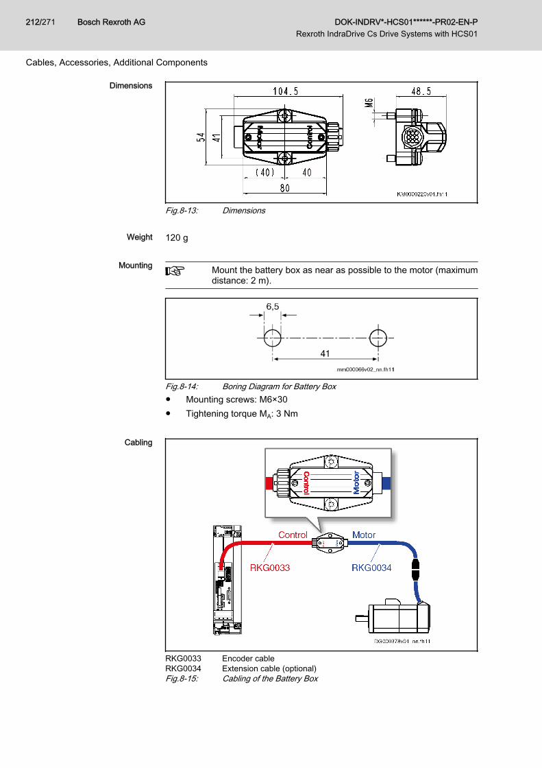
Dimensions
Fig.8-13: Dimensions
Weight 120 g
Mounting Mount the battery box as near as possible to the motor (maximumdistance: 2 m).
Fig.8-14: Boring Diagram for Battery Box● Mounting screws: M6×30● Tightening torque MA: 3 Nm
Cabling
RKG0033 Encoder cableRKG0034 Extension cable (optional)Fig.8-15: Cabling of the Battery Box
Bosch Rexroth AG DOK-INDRV*-HCS01******-PR02-EN-P Rexroth IndraDrive Cs Drive Systems with HCS01
212/271
Cables, Accessories, Additional Components
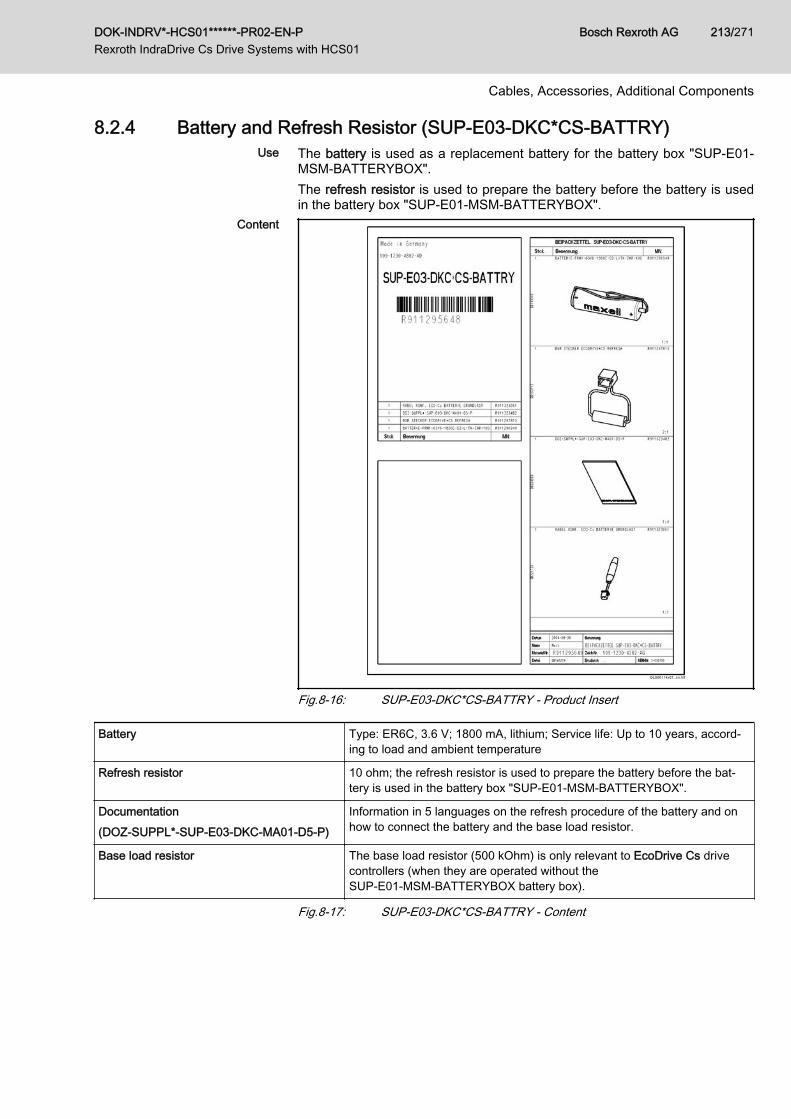
8.2.4 Battery and Refresh Resistor (SUP-E03-DKC*CS-BATTRY)Use The battery is used as a replacement battery for the battery box "SUP-E01-
MSM-BATTERYBOX".The refresh resistor is used to prepare the battery before the battery is usedin the battery box "SUP-E01-MSM-BATTERYBOX".
Content
Fig.8-16: SUP-E03-DKC*CS-BATTRY - Product Insert
Battery Type: ER6C, 3.6 V; 1800 mA, lithium; Service life: Up to 10 years, accord‐ing to load and ambient temperature
Refresh resistor 10 ohm; the refresh resistor is used to prepare the battery before the bat‐tery is used in the battery box "SUP-E01-MSM-BATTERYBOX".
Documentation(DOZ-SUPPL*-SUP-E03-DKC-MA01-D5-P)
Information in 5 languages on the refresh procedure of the battery and onhow to connect the battery and the base load resistor.
Base load resistor The base load resistor (500 kOhm) is only relevant to EcoDrive Cs drivecontrollers (when they are operated without theSUP-E01-MSM-BATTERYBOX battery box).
Fig.8-17: SUP-E03-DKC*CS-BATTRY - Content
DOK-INDRV*-HCS01******-PR02-EN-P Rexroth IndraDrive Cs Drive Systems with HCS01
Bosch Rexroth AG 213/271
Cables, Accessories, Additional Components
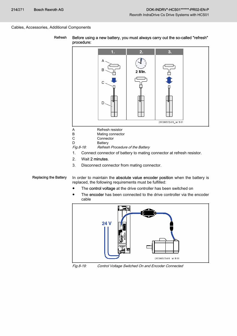
Refresh Before using a new battery, you must always carry out the so-called "refresh"procedure:
A Refresh resistorB Mating connectorC ConnectorD BatteryFig.8-18: Refresh Procedure of the Battery1. Connect connector of battery to mating connector at refresh resistor.2. Wait 2 minutes.3. Disconnect connector from mating connector.
Replacing the Battery In order to maintain the absolute value encoder position when the battery isreplaced, the following requirements must be fulfilled:● The control voltage at the drive controller has been switched on● The encoder has been connected to the drive controller via the encoder
cable
Fig.8-19: Control Voltage Switched On and Encoder Connected
Bosch Rexroth AG DOK-INDRV*-HCS01******-PR02-EN-P Rexroth IndraDrive Cs Drive Systems with HCS01
214/271
Cables, Accessories, Additional Components
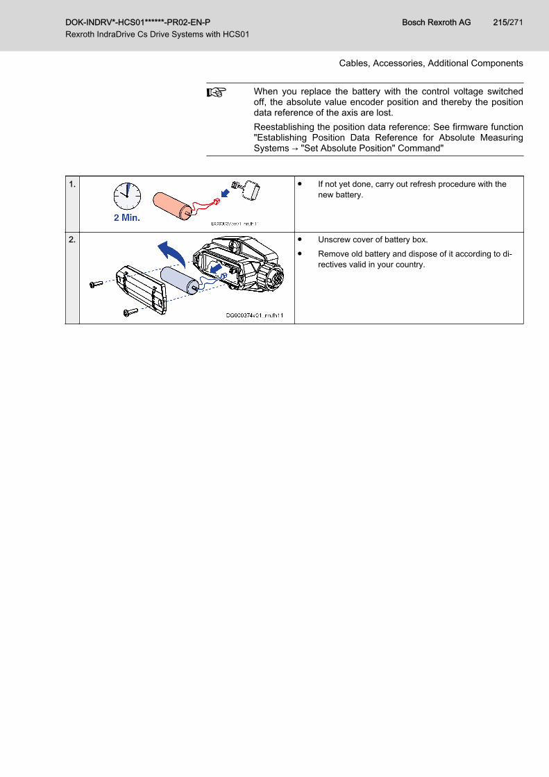
When you replace the battery with the control voltage switchedoff, the absolute value encoder position and thereby the positiondata reference of the axis are lost.Reestablishing the position data reference: See firmware function"Establishing Position Data Reference for Absolute MeasuringSystems → "Set Absolute Position" Command"
1. ● If not yet done, carry out refresh procedure with thenew battery.
2. ● Unscrew cover of battery box.● Remove old battery and dispose of it according to di‐
rectives valid in your country.
DOK-INDRV*-HCS01******-PR02-EN-P Rexroth IndraDrive Cs Drive Systems with HCS01
Bosch Rexroth AG 215/271
Cables, Accessories, Additional Components
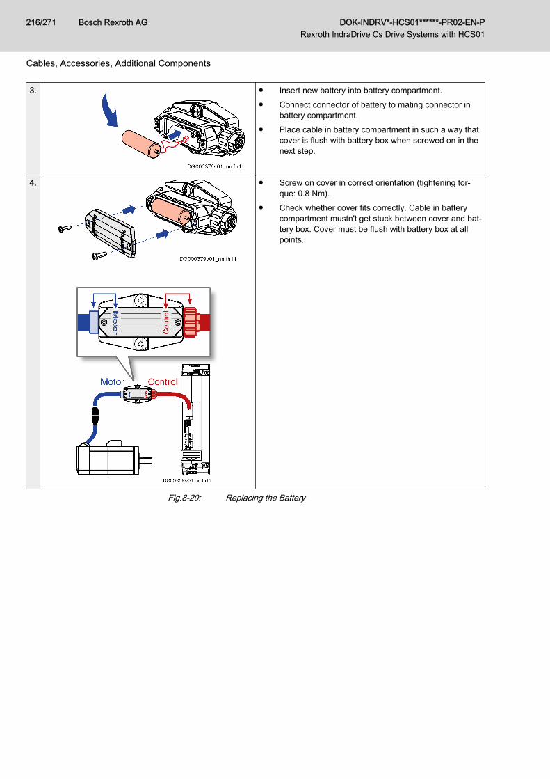
3. ● Insert new battery into battery compartment.● Connect connector of battery to mating connector in
battery compartment.● Place cable in battery compartment in such a way that
cover is flush with battery box when screwed on in thenext step.
4.
● Screw on cover in correct orientation (tightening tor‐que: 0.8 Nm).
● Check whether cover fits correctly. Cable in batterycompartment mustn't get stuck between cover and bat‐tery box. Cover must be flush with battery box at allpoints.
Fig.8-20: Replacing the Battery
Bosch Rexroth AG DOK-INDRV*-HCS01******-PR02-EN-P Rexroth IndraDrive Cs Drive Systems with HCS01
216/271
Cables, Accessories, Additional Components
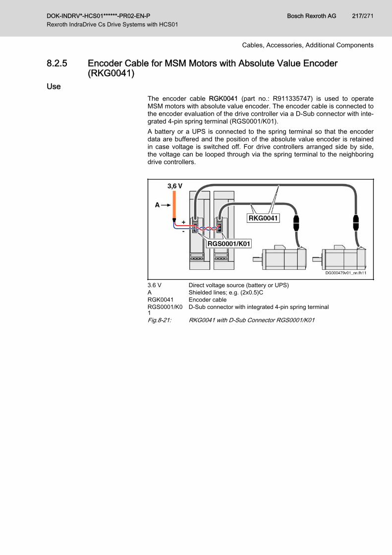
8.2.5 Encoder Cable for MSM Motors with Absolute Value Encoder(RKG0041)
UseThe encoder cable RGK0041 (part no.: R911335747) is used to operateMSM motors with absolute value encoder. The encoder cable is connected tothe encoder evaluation of the drive controller via a D-Sub connector with inte‐grated 4‑pin spring terminal (RGS0001/K01).A battery or a UPS is connected to the spring terminal so that the encoderdata are buffered and the position of the absolute value encoder is retainedin case voltage is switched off. For drive controllers arranged side by side,the voltage can be looped through via the spring terminal to the neighboringdrive controllers.
3.6 V Direct voltage source (battery or UPS)A Shielded lines; e.g. (2x0.5)CRGK0041 Encoder cableRGS0001/K01
D-Sub connector with integrated 4‑pin spring terminal
Fig.8-21: RKG0041 with D-Sub Connector RGS0001/K01
DOK-INDRV*-HCS01******-PR02-EN-P Rexroth IndraDrive Cs Drive Systems with HCS01
Bosch Rexroth AG 217/271
Cables, Accessories, Additional Components
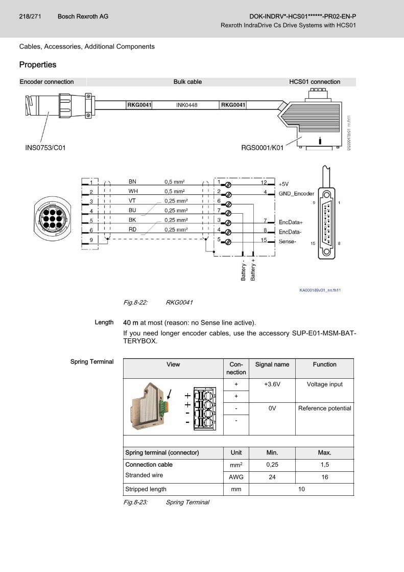
Properties
Encoder connection Bulk cable HCS01 connection
Fig.8-22: RKG0041
Length 40 m at most (reason: no Sense line active).If you need longer encoder cables, use the accessory SUP-E01-MSM-BAT‐TERYBOX.
Spring Terminal View Con‐nection
Signal name Function
+ +3.6V Voltage input
+
- 0V Reference potential
-
Spring terminal (connector) Unit Min. Max.
Connection cableStranded wire
mm2 0,25 1,5
AWG 24 16
Stripped length mm 10
Fig.8-23: Spring Terminal
Bosch Rexroth AG DOK-INDRV*-HCS01******-PR02-EN-P Rexroth IndraDrive Cs Drive Systems with HCS01
218/271
Cables, Accessories, Additional Components
Project PlanningUPS DC 3.6 V ±10%; 1 mA
Battery 3.6 V; lithium
Lithium batteries are long-life batteries and can be stored for a long time. Therequired capacity depends on the desired service life of the battery and thenumber of connected motors. The battery is not included in the scope of sup‐ply and must be ordered separately.● Recommended battery type:
maxell ER6C; 3.6 V / 1.8 Ah(The accessory SUP-E03-DKC*CS-BATTRY (part no.: R911295648)contains this battery.)
● Alternative battery types:– TADIRAN SL760, 3.6 V / 2.1 Ah– JAUCH ER17505, 3.6 V / 3.6 Ah– JAUCH ER34615 3.6 V / 19 Ah
To be observed for transport:The alternative battery types have a relatively high content of lithi‐um and are hazardous material Class 9.
Selecting the Battery Capacity 1.8 Ah per drive
The base load resistance in the D-Sub connector has been adjusted to thisbattery capacity. The service life of the battery depends on the switch-on andswitch-off times of the drive and with a battery capacity of 1.8 Ah it is approx.2 to 10 years.Battery current per drive (encoder current + base load current):● Drive Off: Approx. 70 μA● Drive On: Approx. 10 μA
Battery Base Load and BatteryCapacity
The D-Sub connector contains a base load resistance of 499 kΩ. The baseload resistance causes a standby current of 7 μA which must flow with3.6 V / 1.8 Ah for a lithium battery. This avoids premature aging of the batteryand a relatively long service life.If you use a bigger battery (> 1.8 Ah) at one D-Sub connector only, connectan external resistor at the 4-pin spring terminal so that a higher standby cur‐rent flows.How to calculate the external resistance (Rext):Rext = 3.6 V / Iext
Iext = [battery capacity / 1.8 Ah] × 7 μA - (7 μA × number_connectors)Examples● 1 D-Sub connector + battery 1.8 Ah ⇒
No additional base load resistance required
DOK-INDRV*-HCS01******-PR02-EN-P Rexroth IndraDrive Cs Drive Systems with HCS01
Bosch Rexroth AG 219/271
Cables, Accessories, Additional Components
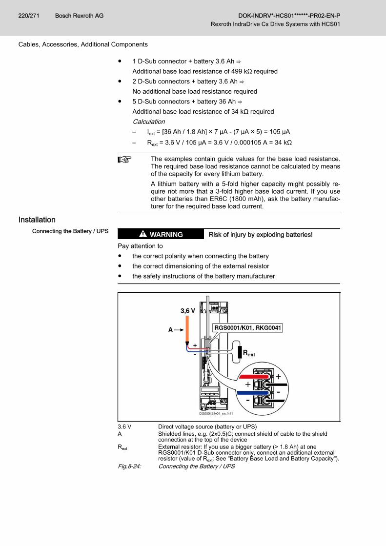
● 1 D-Sub connector + battery 3.6 Ah ⇒Additional base load resistance of 499 kΩ required
● 2 D-Sub connectors + battery 3.6 Ah ⇒No additional base load resistance required
● 5 D-Sub connectors + battery 36 Ah ⇒Additional base load resistance of 34 kΩ requiredCalculation– Iext = [36 Ah / 1.8 Ah] × 7 μA - (7 μA × 5) = 105 μA– Rext = 3.6 V / 105 μA = 3.6 V / 0.000105 A = 34 kΩ
The examples contain guide values for the base load resistance.The required base load resistance cannot be calculated by meansof the capacity for every lithium battery.A lithium battery with a 5-fold higher capacity might possibly re‐quire not more that a 3-fold higher base load current. If you useother batteries than ER6C (1800 mAh), ask the battery manufac‐turer for the required base load current.
InstallationConnecting the Battery / UPS Risk of injury by exploding batteries!WARNING
Pay attention to● the correct polarity when connecting the battery● the correct dimensioning of the external resistor● the safety instructions of the battery manufacturer
3.6 V Direct voltage source (battery or UPS)A Shielded lines, e.g. (2x0.5)C; connect shield of cable to the shield
connection at the top of the deviceRext External resistor: If you use a bigger battery (> 1.8 Ah) at one
RGS0001/K01 D-Sub connector only, connect an additional externalresistor (value of Rext: See "Battery Base Load and Battery Capacity").
Fig.8-24: Connecting the Battery / UPS
Bosch Rexroth AG DOK-INDRV*-HCS01******-PR02-EN-P Rexroth IndraDrive Cs Drive Systems with HCS01
220/271
Cables, Accessories, Additional Components
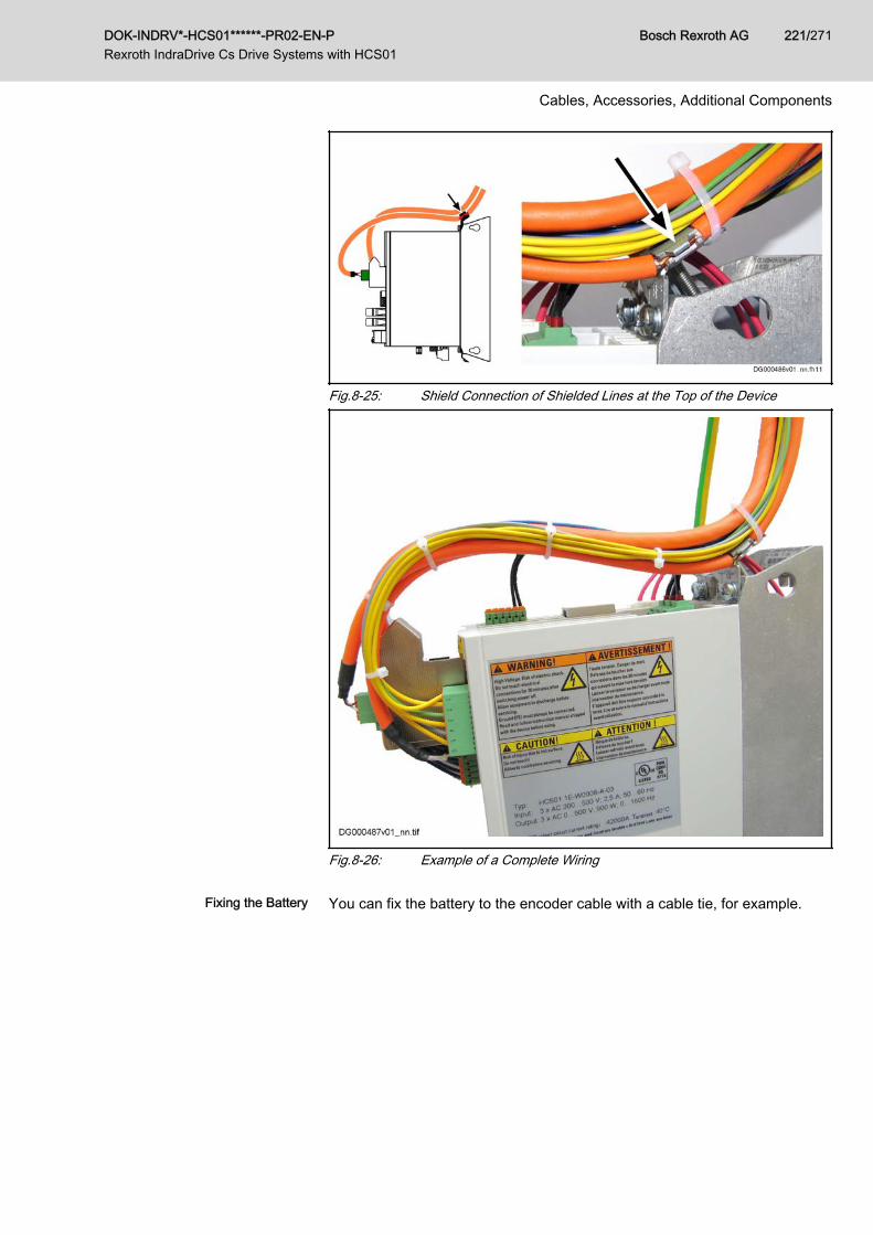
Fig.8-25: Shield Connection of Shielded Lines at the Top of the Device
Fig.8-26: Example of a Complete Wiring
Fixing the Battery You can fix the battery to the encoder cable with a cable tie, for example.
DOK-INDRV*-HCS01******-PR02-EN-P Rexroth IndraDrive Cs Drive Systems with HCS01
Bosch Rexroth AG 221/271
Cables, Accessories, Additional Components
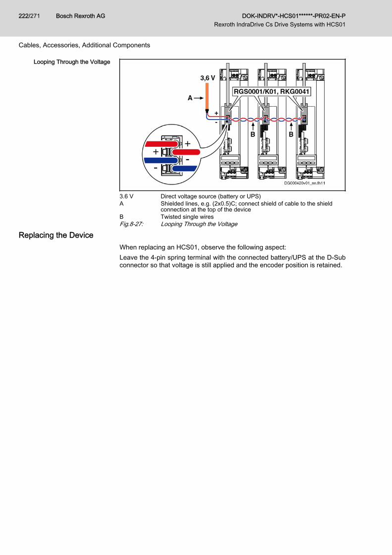
Looping Through the Voltage
3.6 V Direct voltage source (battery or UPS)A Shielded lines, e.g. (2x0.5)C; connect shield of cable to the shield
connection at the top of the deviceB Twisted single wiresFig.8-27: Looping Through the Voltage
Replacing the DeviceWhen replacing an HCS01, observe the following aspect:Leave the 4-pin spring terminal with the connected battery/UPS at the D-Subconnector so that voltage is still applied and the encoder position is retained.
Bosch Rexroth AG DOK-INDRV*-HCS01******-PR02-EN-P Rexroth IndraDrive Cs Drive Systems with HCS01
222/271
Cables, Accessories, Additional Components
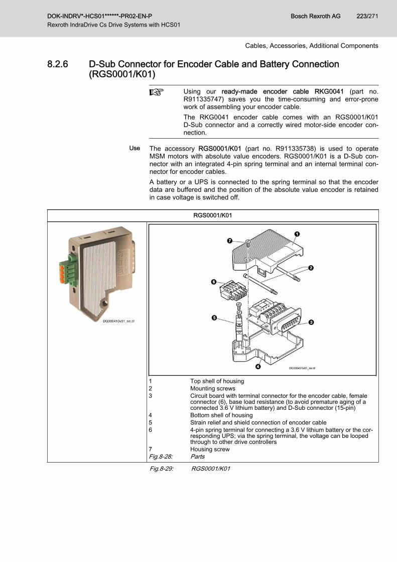
8.2.6 D-Sub Connector for Encoder Cable and Battery Connection(RGS0001/K01)
Using our ready-made encoder cable RKG0041 (part no.R911335747) saves you the time-consuming and error-pronework of assembling your encoder cable.The RKG0041 encoder cable comes with an RGS0001/K01D‑Sub connector and a correctly wired motor-side encoder con‐nection.
Use The accessory RGS0001/K01 (part no. R911335738) is used to operateMSM motors with absolute value encoders. RGS0001/K01 is a D-Sub con‐nector with an integrated 4‑pin spring terminal and an internal terminal con‐nector for encoder cables.A battery or a UPS is connected to the spring terminal so that the encoderdata are buffered and the position of the absolute value encoder is retainedin case voltage is switched off.
RGS0001/K01
1 Top shell of housing2 Mounting screws3 Circuit board with terminal connector for the encoder cable, female
connector (6), base load resistance (to avoid premature aging of aconnected 3.6 V lithium battery) and D‑Sub connector (15‑pin)
4 Bottom shell of housing5 Strain relief and shield connection of encoder cable6 4-pin spring terminal for connecting a 3.6 V lithium battery or the cor‐
responding UPS; via the spring terminal, the voltage can be loopedthrough to other drive controllers
7 Housing screwFig.8-28: Parts
Fig.8-29: RGS0001/K01
DOK-INDRV*-HCS01******-PR02-EN-P Rexroth IndraDrive Cs Drive Systems with HCS01
Bosch Rexroth AG 223/271
Cables, Accessories, Additional Components
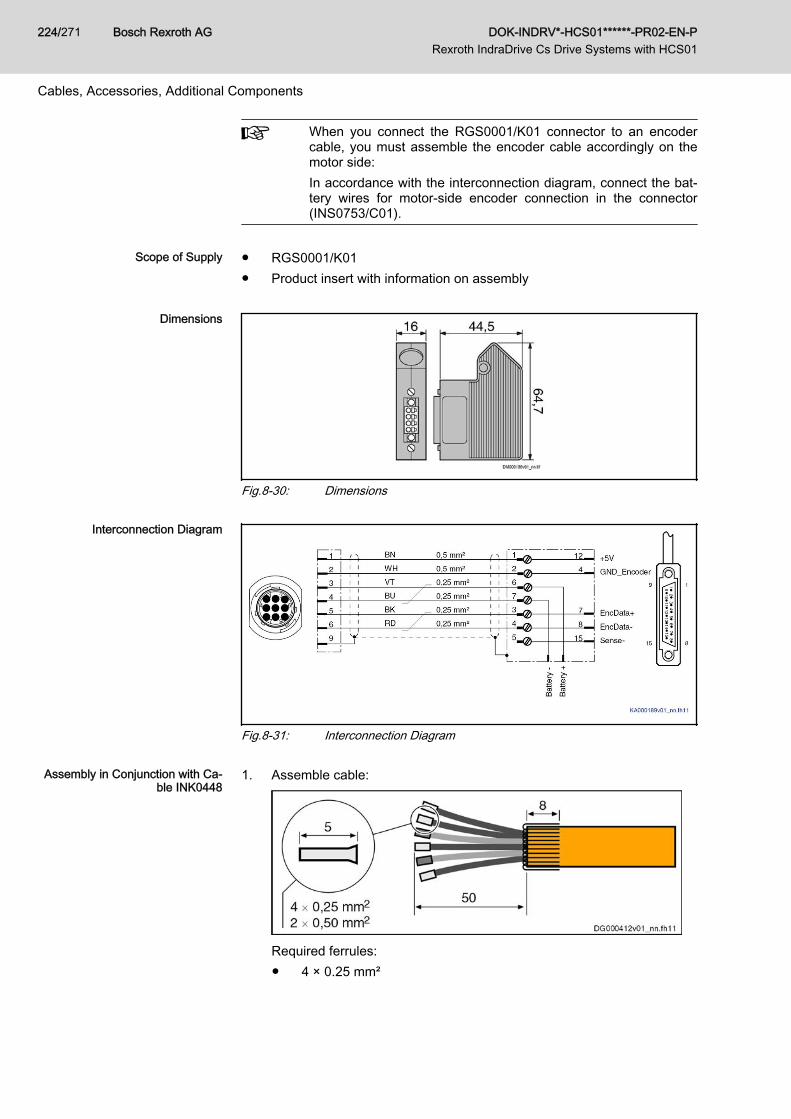
When you connect the RGS0001/K01 connector to an encodercable, you must assemble the encoder cable accordingly on themotor side:In accordance with the interconnection diagram, connect the bat‐tery wires for motor-side encoder connection in the connector(INS0753/C01).
Scope of Supply ● RGS0001/K01
● Product insert with information on assembly
Dimensions
Fig.8-30: Dimensions
Interconnection Diagram
Fig.8-31: Interconnection Diagram
Assembly in Conjunction with Ca‐ble INK0448
1. Assemble cable:
Required ferrules:● 4 × 0.25 mm²
Bosch Rexroth AG DOK-INDRV*-HCS01******-PR02-EN-P Rexroth IndraDrive Cs Drive Systems with HCS01
224/271
Cables, Accessories, Additional Components
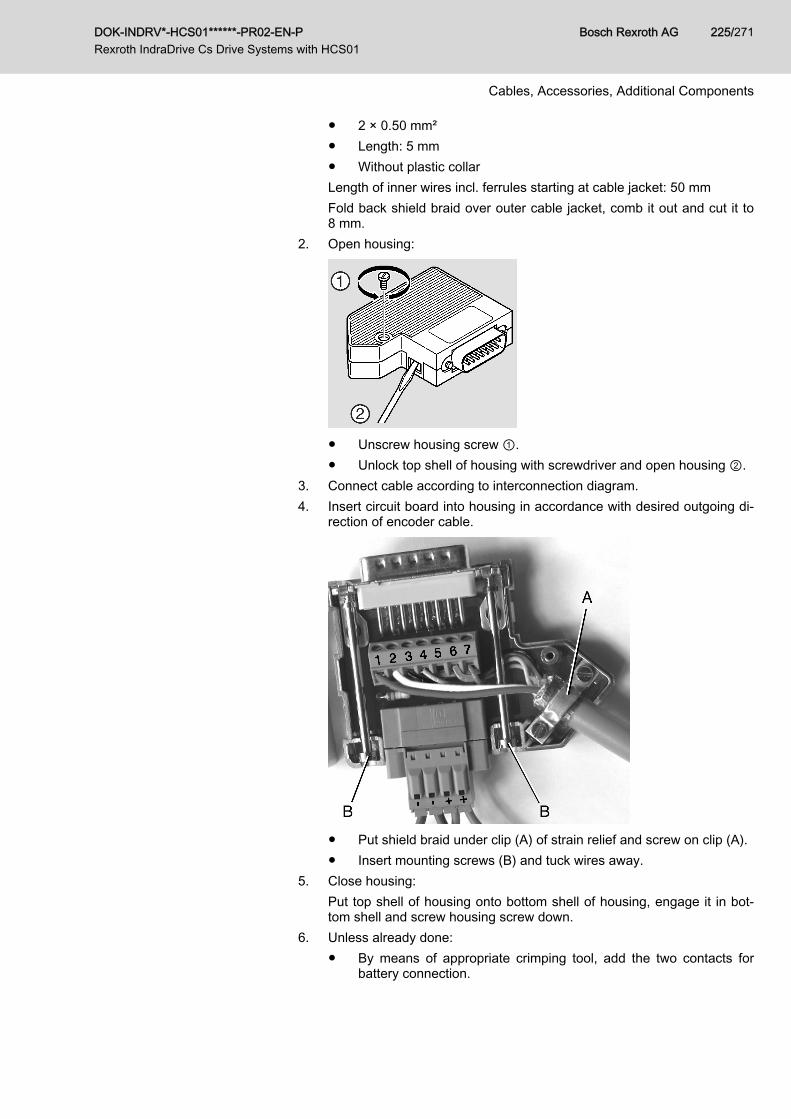
● 2 × 0.50 mm²● Length: 5 mm● Without plastic collarLength of inner wires incl. ferrules starting at cable jacket: 50 mmFold back shield braid over outer cable jacket, comb it out and cut it to8 mm.
2. Open housing:
● Unscrew housing screw ①.● Unlock top shell of housing with screwdriver and open housing ②.
3. Connect cable according to interconnection diagram.4. Insert circuit board into housing in accordance with desired outgoing di‐
rection of encoder cable.
● Put shield braid under clip (A) of strain relief and screw on clip (A).● Insert mounting screws (B) and tuck wires away.
5. Close housing:Put top shell of housing onto bottom shell of housing, engage it in bot‐tom shell and screw housing screw down.
6. Unless already done:● By means of appropriate crimping tool, add the two contacts for
battery connection.
DOK-INDRV*-HCS01******-PR02-EN-P Rexroth IndraDrive Cs Drive Systems with HCS01
Bosch Rexroth AG 225/271
Cables, Accessories, Additional Components
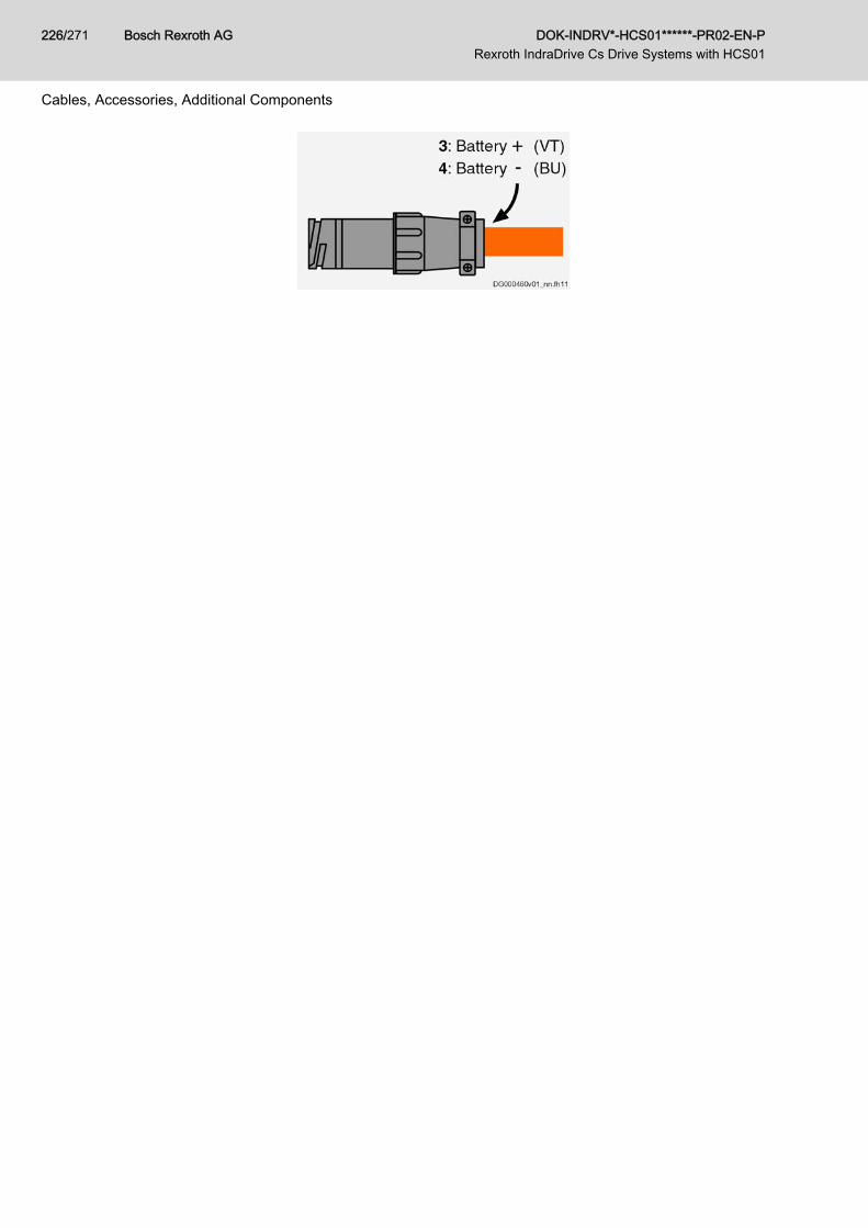
Bosch Rexroth AG DOK-INDRV*-HCS01******-PR02-EN-P Rexroth IndraDrive Cs Drive Systems with HCS01
226/271
Cables, Accessories, Additional Components
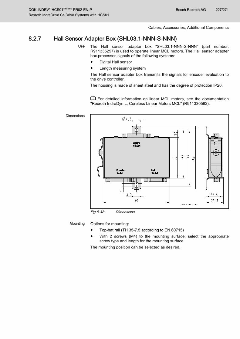
8.2.7 Hall Sensor Adapter Box (SHL03.1-NNN-S-NNN)Use The Hall sensor adapter box "SHL03.1-NNN-S-NNN" (part number:
R911335257) is used to operate linear MCL motors. The Hall sensor adapterbox processes signals of the following systems:● Digital Hall sensor● Length measuring systemThe Hall sensor adapter box transmits the signals for encoder evaluation tothe drive controller.The housing is made of sheet steel and has the degree of protection IP20.
For detailed information on linear MCL motors, see the documentation"Rexroth IndraDyn L, Coreless Linear Motors MCL" (R911330592).
Dimensions
Fig.8-32: Dimensions
Mounting Options for mounting:● Top-hat rail (TH 35-7.5 according to EN 60715)● With 2 screws (M4) to the mounting surface; select the appropriate
screw type and length for the mounting surfaceThe mounting position can be selected as desired.
DOK-INDRV*-HCS01******-PR02-EN-P Rexroth IndraDrive Cs Drive Systems with HCS01
Bosch Rexroth AG 227/271
Cables, Accessories, Additional Components
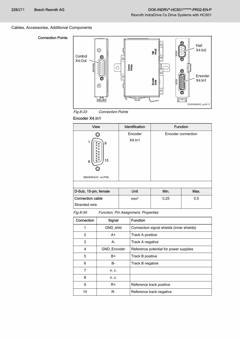
Connection Points
Fig.8-33: Connection PointsEncoder X4.In1
View Identification Function
EncoderX4.In1
Encoder connection
D-Sub, 15-pin, female Unit Min. Max.
Connection cableStranded wire
mm2 0,25 0,5
Fig.8-34: Function, Pin Assignment, Properties
Connection Signal Function
1 GND_shld Connection signal shields (inner shields)
2 A+ Track A positive
3 A- Track A negative
4 GND_Encoder Reference potential for power supplies
5 B+ Track B positive
6 B- Track B negative
7 n. c.
8 n. c.
9 R+ Reference track positive
10 R- Reference track negative
Bosch Rexroth AG DOK-INDRV*-HCS01******-PR02-EN-P Rexroth IndraDrive Cs Drive Systems with HCS01
228/271
Cables, Accessories, Additional Components
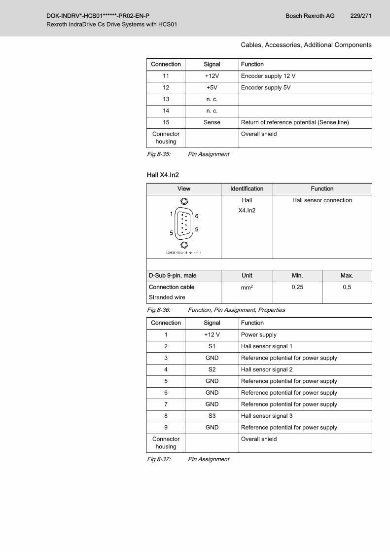
Connection Signal Function
11 +12V Encoder supply 12 V
12 +5V Encoder supply 5V
13 n. c.
14 n. c.
15 Sense Return of reference potential (Sense line)
Connectorhousing
Overall shield
Fig.8-35: Pin Assignment Hall X4.In2
View Identification Function
HallX4.In2
Hall sensor connection
D-Sub 9-pin, male Unit Min. Max.
Connection cableStranded wire
mm2 0,25 0,5
Fig.8-36: Function, Pin Assignment, Properties
Connection Signal Function
1 +12 V Power supply
2 S1 Hall sensor signal 1
3 GND Reference potential for power supply
4 S2 Hall sensor signal 2
5 GND Reference potential for power supply
6 GND Reference potential for power supply
7 GND Reference potential for power supply
8 S3 Hall sensor signal 3
9 GND Reference potential for power supply
Connectorhousing
Overall shield
Fig.8-37: Pin Assignment
DOK-INDRV*-HCS01******-PR02-EN-P Rexroth IndraDrive Cs Drive Systems with HCS01
Bosch Rexroth AG 229/271
Cables, Accessories, Additional Components
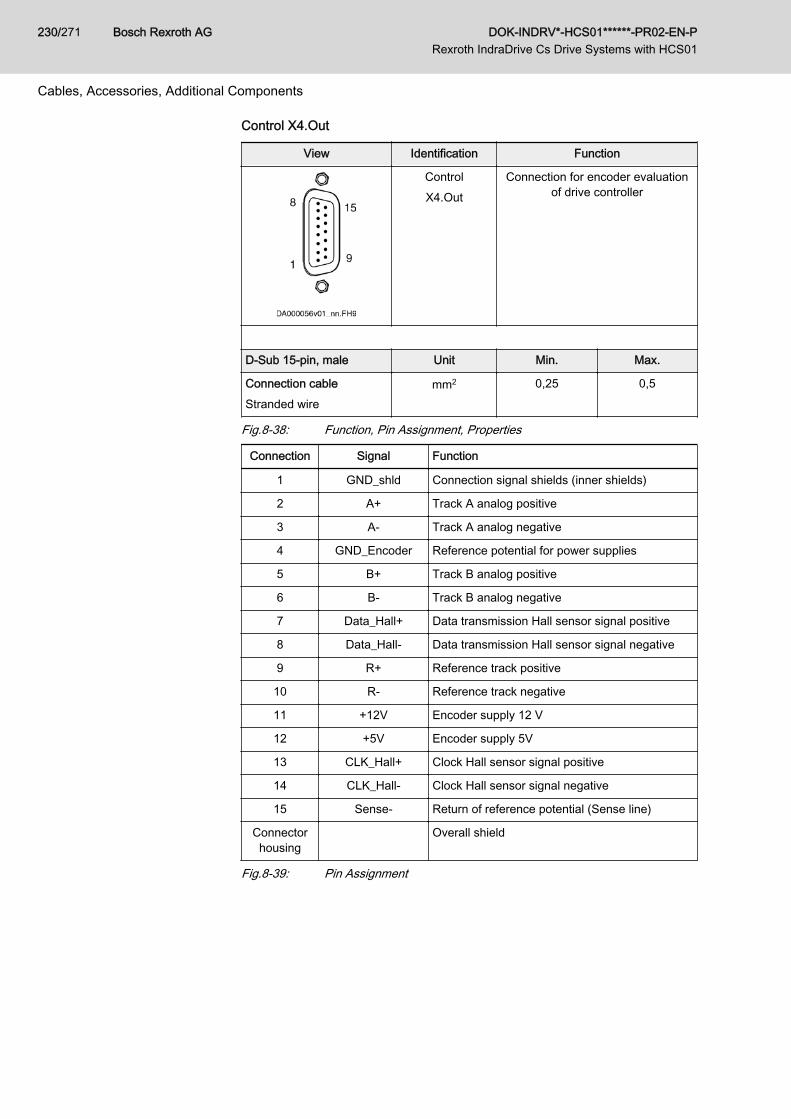
Control X4.Out
View Identification Function
ControlX4.Out
Connection for encoder evaluationof drive controller
D-Sub 15-pin, male Unit Min. Max.
Connection cableStranded wire
mm2 0,25 0,5
Fig.8-38: Function, Pin Assignment, Properties
Connection Signal Function
1 GND_shld Connection signal shields (inner shields)
2 A+ Track A analog positive
3 A- Track A analog negative
4 GND_Encoder Reference potential for power supplies
5 B+ Track B analog positive
6 B- Track B analog negative
7 Data_Hall+ Data transmission Hall sensor signal positive
8 Data_Hall- Data transmission Hall sensor signal negative
9 R+ Reference track positive
10 R- Reference track negative
11 +12V Encoder supply 12 V
12 +5V Encoder supply 5V
13 CLK_Hall+ Clock Hall sensor signal positive
14 CLK_Hall- Clock Hall sensor signal negative
15 Sense- Return of reference potential (Sense line)
Connectorhousing
Overall shield
Fig.8-39: Pin Assignment
Bosch Rexroth AG DOK-INDRV*-HCS01******-PR02-EN-P Rexroth IndraDrive Cs Drive Systems with HCS01
230/271
Cables, Accessories, Additional Components
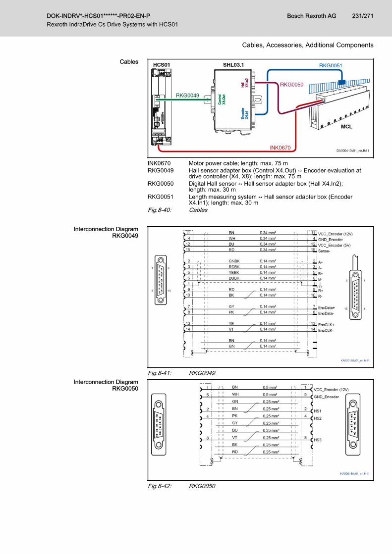
Cables
INK0670 Motor power cable; length: max. 75 mRKG0049 Hall sensor adapter box (Control X4.Out) ↔ Encoder evaluation at
drive controller (X4, X8); length: max. 75 mRKG0050 Digital Hall sensor ↔ Hall sensor adapter box (Hall X4.In2);
length: max. 30 mRKG0051 Length measuring system ↔ Hall sensor adapter box (Encoder
X4.In1); length: max. 30 mFig.8-40: Cables
Interconnection DiagramRKG0049
Fig.8-41: RKG0049Interconnection Diagram
RKG0050
Fig.8-42: RKG0050
DOK-INDRV*-HCS01******-PR02-EN-P Rexroth IndraDrive Cs Drive Systems with HCS01
Bosch Rexroth AG 231/271
Cables, Accessories, Additional Components
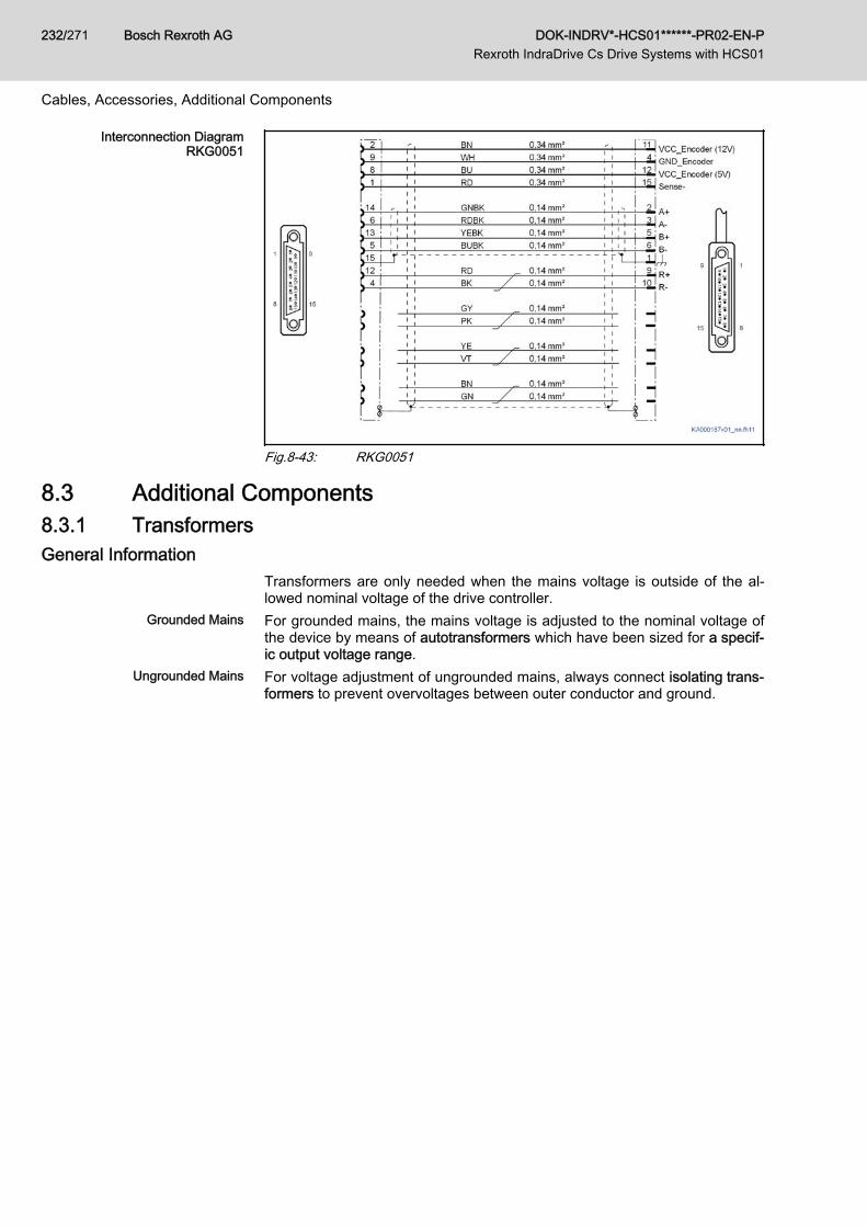
Interconnection DiagramRKG0051
Fig.8-43: RKG0051
8.3 Additional Components8.3.1 TransformersGeneral Information
Transformers are only needed when the mains voltage is outside of the al‐lowed nominal voltage of the drive controller.
Grounded Mains For grounded mains, the mains voltage is adjusted to the nominal voltage ofthe device by means of autotransformers which have been sized for a specif‐ic output voltage range.
Ungrounded Mains For voltage adjustment of ungrounded mains, always connect isolating trans‐formers to prevent overvoltages between outer conductor and ground.
Bosch Rexroth AG DOK-INDRV*-HCS01******-PR02-EN-P Rexroth IndraDrive Cs Drive Systems with HCS01
232/271
Cables, Accessories, Additional Components
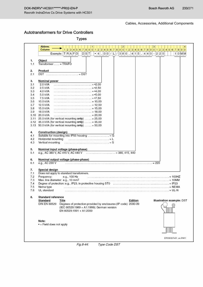
Autotransformers for Drive ControllersTypes
Fig.8-44: Type Code DST
DOK-INDRV*-HCS01******-PR02-EN-P Rexroth IndraDrive Cs Drive Systems with HCS01
Bosch Rexroth AG 233/271
Cables, Accessories, Additional Components
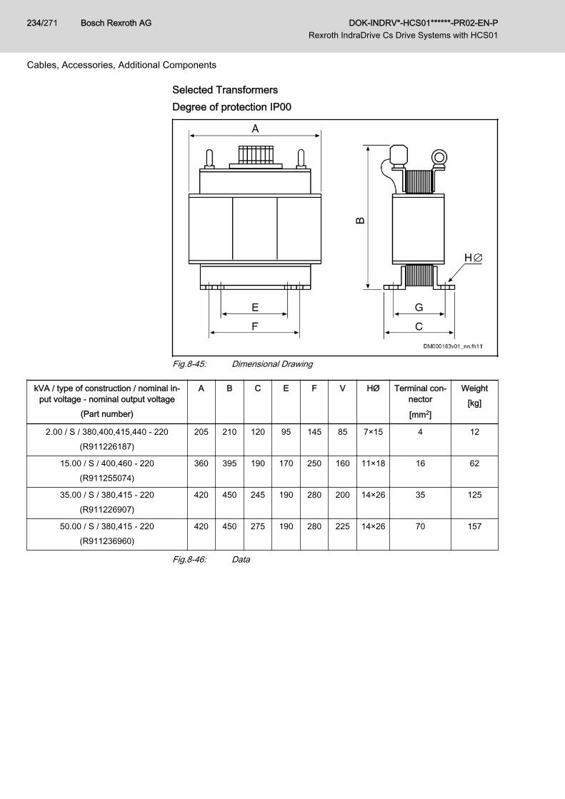
Selected TransformersDegree of protection IP00
Fig.8-45: Dimensional Drawing
kVA / type of construction / nominal in‐put voltage - nominal output voltage
(Part number)
A B C E F V HØ Terminal con‐nector
[mm2]
Weight[kg]
2.00 / S / 380,400,415,440 - 220(R911226187)
205 210 120 95 145 85 7×15 4 12
15.00 / S / 400,460 - 220(R911255074)
360 395 190 170 250 160 11×18 16 62
35.00 / S / 380,415 - 220(R911226907)
420 450 245 190 280 200 14×26 35 125
50.00 / S / 380,415 - 220(R911236960)
420 450 275 190 280 225 14×26 70 157
Fig.8-46: Data
Bosch Rexroth AG DOK-INDRV*-HCS01******-PR02-EN-P Rexroth IndraDrive Cs Drive Systems with HCS01
234/271
Cables, Accessories, Additional Components
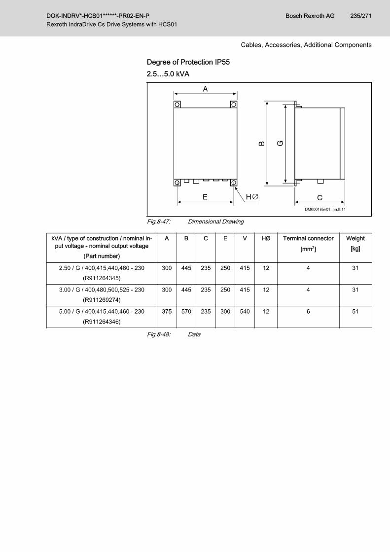
Degree of Protection IP552.5…5.0 kVA
Fig.8-47: Dimensional Drawing
kVA / type of construction / nominal in‐put voltage - nominal output voltage
(Part number)
A B C E V HØ Terminal connector
[mm2]
Weight[kg]
2.50 / G / 400,415,440,460 - 230(R911264345)
300 445 235 250 415 12 4 31
3.00 / G / 400,480,500,525 - 230(R911269274)
300 445 235 250 415 12 4 31
5.00 / G / 400,415,440,460 - 230(R911264346)
375 570 235 300 540 12 6 51
Fig.8-48: Data
DOK-INDRV*-HCS01******-PR02-EN-P Rexroth IndraDrive Cs Drive Systems with HCS01
Bosch Rexroth AG 235/271
Cables, Accessories, Additional Components
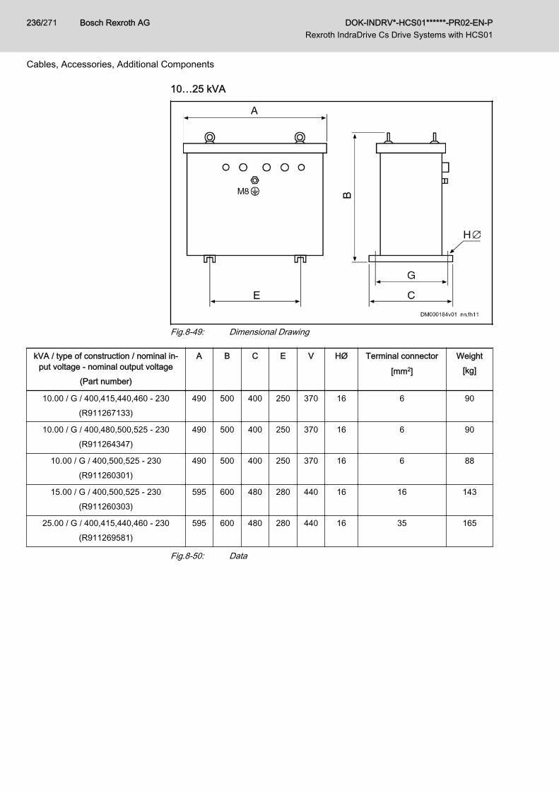
10…25 kVA
Fig.8-49: Dimensional Drawing
kVA / type of construction / nominal in‐put voltage - nominal output voltage
(Part number)
A B C E V HØ Terminal connector
[mm2]
Weight[kg]
10.00 / G / 400,415,440,460 - 230(R911267133)
490 500 400 250 370 16 6 90
10.00 / G / 400,480,500,525 - 230(R911264347)
490 500 400 250 370 16 6 90
10.00 / G / 400,500,525 - 230(R911260301)
490 500 400 250 370 16 6 88
15.00 / G / 400,500,525 - 230(R911260303)
595 600 480 280 440 16 16 143
25.00 / G / 400,415,440,460 - 230(R911269581)
595 600 480 280 440 16 35 165
Fig.8-50: Data
Bosch Rexroth AG DOK-INDRV*-HCS01******-PR02-EN-P Rexroth IndraDrive Cs Drive Systems with HCS01
236/271
Cables, Accessories, Additional Components
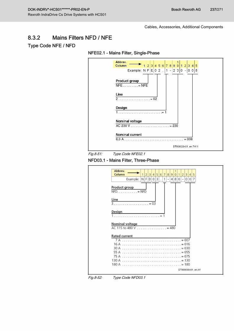
8.3.2 Mains Filters NFD / NFEType Code NFE / NFD
NFE02.1 - Mains Filter, Single-Phase
Fig.8-51: Type Code NFE02.1
NFD03.1 - Mains Filter, Three-Phase
Fig.8-52: Type Code NFD03.1
DOK-INDRV*-HCS01******-PR02-EN-P Rexroth IndraDrive Cs Drive Systems with HCS01
Bosch Rexroth AG 237/271
Cables, Accessories, Additional Components
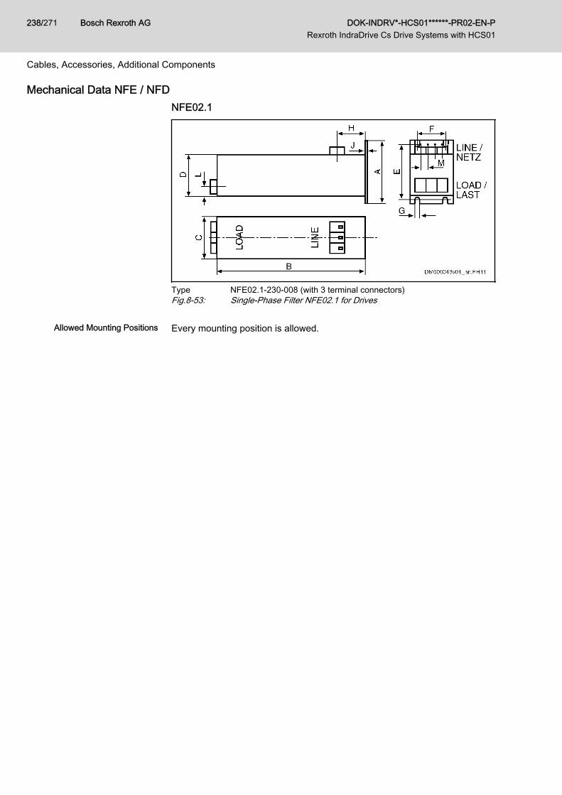
Mechanical Data NFE / NFDNFE02.1
Type NFE02.1-230-008 (with 3 terminal connectors)Fig.8-53: Single-Phase Filter NFE02.1 for Drives
Allowed Mounting Positions Every mounting position is allowed.
Bosch Rexroth AG DOK-INDRV*-HCS01******-PR02-EN-P Rexroth IndraDrive Cs Drive Systems with HCS01
238/271
Cables, Accessories, Additional Components
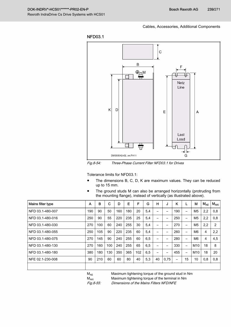
NFD03.1
Fig.8-54: Three-Phase Current Filter NFD03.1 for Drives Tolerance limits for NFD03.1:● The dimensions B, C, D, K are maximum values. They can be reduced
up to 15 mm.● The ground studs M can also be arranged horizontally (protruding from
the mounting flange), instead of vertically (as illustrated above).
Mains filter type A B C D E F G H J K L M MAE MAKl
NFD 03.1-480-007 190 90 50 160 180 20 5,4 – – 190 – M5 2,2 0,8
NFD 03.1-480-016 250 90 55 220 235 25 5,4 – – 250 – M5 2,2 0,8
NFD 03.1-480-030 270 100 60 240 255 30 5,4 – – 270 – M5 2,2 2
NFD 03.1-480-055 250 105 90 220 235 60 5,4 – – 260 – M6 4 2,2
NFD 03.1-480-075 270 145 90 240 255 60 6,5 – – 280 – M6 4 4,5
NFD 03.1-480-130 270 160 100 240 255 65 6,5 – – 330 – M10 18 8
NFD 03.1-480-180 380 180 130 350 365 102 6,5 – – 455 – M10 18 20
NFE 02.1-230-008 90 210 60 60 80 40 5,3 40 0,75 – 15 10 0,8 0,8
MAE Maximum tightening torque of the ground stud in NmMAKl Maximum tightening torque of the terminal in NmFig.8-55: Dimensions of the Mains Filters NFD/NFE
DOK-INDRV*-HCS01******-PR02-EN-P Rexroth IndraDrive Cs Drive Systems with HCS01
Bosch Rexroth AG 239/271
Cables, Accessories, Additional Components
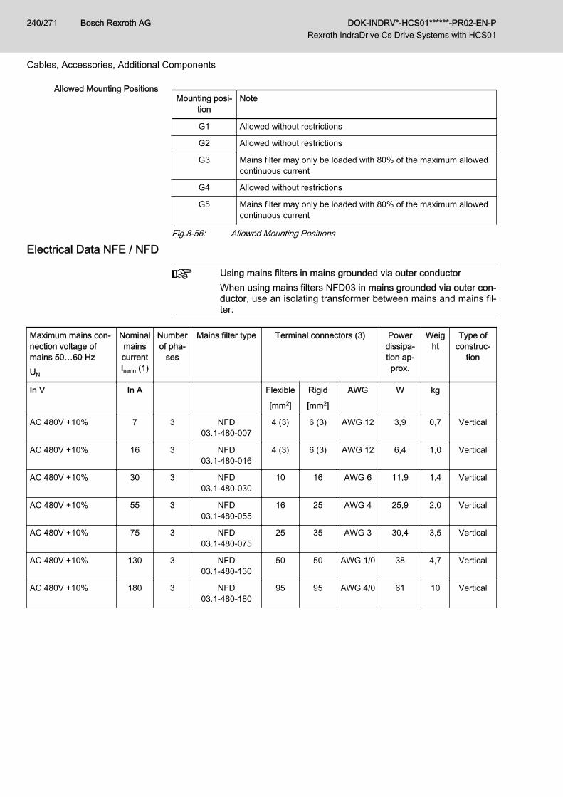
Allowed Mounting PositionsMounting posi‐
tionNote
G1 Allowed without restrictions
G2 Allowed without restrictions
G3 Mains filter may only be loaded with 80% of the maximum allowedcontinuous current
G4 Allowed without restrictions
G5 Mains filter may only be loaded with 80% of the maximum allowedcontinuous current
Fig.8-56: Allowed Mounting Positions
Electrical Data NFE / NFD
Using mains filters in mains grounded via outer conductorWhen using mains filters NFD03 in mains grounded via outer con‐ductor, use an isolating transformer between mains and mains fil‐ter.
Maximum mains con‐nection voltage ofmains 50…60 HzUN
NominalmainscurrentInenn (1)
Numberof pha‐
ses
Mains filter type Terminal connectors (3) Powerdissipa‐tion ap‐prox.
Weight
Type ofconstruc‐
tion
In V In A Flexible
[mm2]
Rigid
[mm2]
AWG W kg
AC 480V +10% 7 3 NFD03.1-480-007
4 (3) 6 (3) AWG 12 3,9 0,7 Vertical
AC 480V +10% 16 3 NFD03.1-480-016
4 (3) 6 (3) AWG 12 6,4 1,0 Vertical
AC 480V +10% 30 3 NFD03.1-480-030
10 16 AWG 6 11,9 1,4 Vertical
AC 480V +10% 55 3 NFD03.1-480-055
16 25 AWG 4 25,9 2,0 Vertical
AC 480V +10% 75 3 NFD03.1-480-075
25 35 AWG 3 30,4 3,5 Vertical
AC 480V +10% 130 3 NFD03.1-480-130
50 50 AWG 1/0 38 4,7 Vertical
AC 480V +10% 180 3 NFD03.1-480-180
95 95 AWG 4/0 61 10 Vertical
Bosch Rexroth AG DOK-INDRV*-HCS01******-PR02-EN-P Rexroth IndraDrive Cs Drive Systems with HCS01
240/271
Cables, Accessories, Additional Components
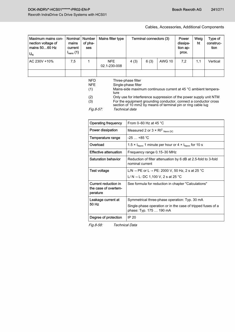
Maximum mains con‐nection voltage ofmains 50…60 HzUN
NominalmainscurrentInenn (1)
Numberof pha‐
ses
Mains filter type Terminal connectors (3) Powerdissipa‐tion ap‐prox.
Weight
Type ofconstruc‐
tion
AC 230V +10% 7,5 1 NFE02.1-230-008
4 (3) 6 (3) AWG 10 7,2 1,1 Vertical
NFD Three-phase filterNFE Single-phase filter(1) Mains-side maximum continuous current at 45 °C ambient tempera‐
ture(2) Only use for interference suppression of the power supply unit NTM(3) For the equipment grounding conductor, connect a conductor cross
section of 10 mm2 by means of terminal pin or ring cable lugFig.8-57: Technical data
Operating frequency From 0–60 Hz at 45 °C
Power dissipation Measured 2 or 3 × RI2 Nenn DC
Temperature range -25 … +85 ℃
Overload 1.5 × INenn 1 minute per hour or 4 × INenn for 10 s
Effective attenuation Frequency range 0.15–30 MHz
Saturation behavior Reduction of filter attenuation by 6 dB at 2.5-fold to 3-foldnominal current
Test voltage L/N → PE or L → PE: 2000 V, 50 Hz, 2 s at 25 °CL/ N → L: DC 1,100 V, 2 s at 25 °C
Current reduction inthe case of overtem‐perature
See formula for reduction in chapter "Calculations"
Leakage current at50 Hz
Symmetrical three-phase operation: Typ. 30 mASingle-phase operation or in the case of tripped fuses of aphase: Typ. 175 … 190 mA
Degree of protection IP 20
Fig.8-58: Technical Data
DOK-INDRV*-HCS01******-PR02-EN-P Rexroth IndraDrive Cs Drive Systems with HCS01
Bosch Rexroth AG 241/271
Cables, Accessories, Additional Components
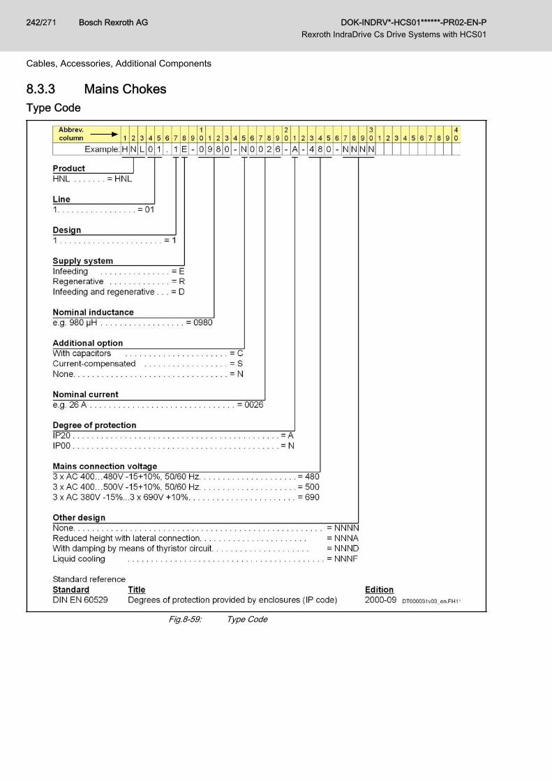
8.3.3 Mains ChokesType Code
Fig.8-59: Type Code
Bosch Rexroth AG DOK-INDRV*-HCS01******-PR02-EN-P Rexroth IndraDrive Cs Drive Systems with HCS01
242/271
Cables, Accessories, Additional Components
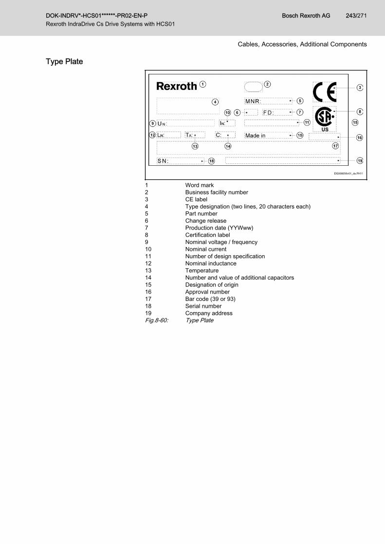
Type Plate
1 Word mark2 Business facility number3 CE label4 Type designation (two lines, 20 characters each)5 Part number6 Change release7 Production date (YYWww)8 Certification label9 Nominal voltage / frequency10 Nominal current11 Number of design specification12 Nominal inductance13 Temperature14 Number and value of additional capacitors15 Designation of origin16 Approval number17 Bar code (39 or 93)18 Serial number19 Company addressFig.8-60: Type Plate
DOK-INDRV*-HCS01******-PR02-EN-P Rexroth IndraDrive Cs Drive Systems with HCS01
Bosch Rexroth AG 243/271
Cables, Accessories, Additional Components
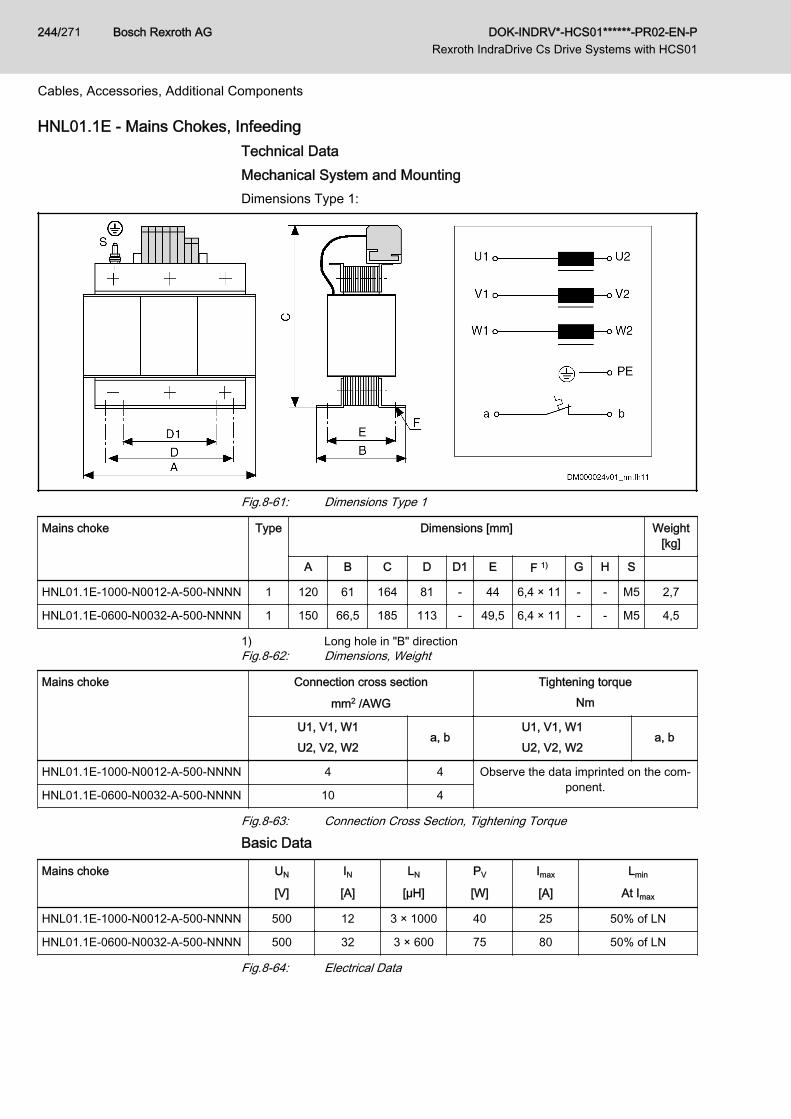
HNL01.1E - Mains Chokes, Infeeding Technical DataMechanical System and MountingDimensions Type 1:
Fig.8-61: Dimensions Type 1
Mains choke Type Dimensions [mm] Weight[kg]
A B C D D1 E F 1) G H S
HNL01.1E-1000-N0012-A-500-NNNN 1 120 61 164 81 - 44 6,4 × 11 - - M5 2,7
HNL01.1E-0600-N0032-A-500-NNNN 1 150 66,5 185 113 - 49,5 6,4 × 11 - - M5 4,5
1) Long hole in "B" directionFig.8-62: Dimensions, Weight
Mains choke Connection cross section
mm2 /AWG
Tightening torqueNm
U1, V1, W1U2, V2, W2
a, bU1, V1, W1U2, V2, W2
a, b
HNL01.1E-1000-N0012-A-500-NNNN 4 4 Observe the data imprinted on the com‐ponent.HNL01.1E-0600-N0032-A-500-NNNN 10 4
Fig.8-63: Connection Cross Section, Tightening Torque
Basic Data
Mains choke UN
[V]
IN[A]
LN
[µH]
PV
[W]
Imax
[A]
Lmin
At Imax
HNL01.1E-1000-N0012-A-500-NNNN 500 12 3 × 1000 40 25 50% of LN
HNL01.1E-0600-N0032-A-500-NNNN 500 32 3 × 600 75 80 50% of LN
Fig.8-64: Electrical Data
Bosch Rexroth AG DOK-INDRV*-HCS01******-PR02-EN-P Rexroth IndraDrive Cs Drive Systems with HCS01
244/271
Cables, Accessories, Additional Components

Temperature Contact a, bSwitching capacity Switching temperature
1 A / AC 250 VDC 24 V
125 ℃HNL01.1E mains chokes of type 1 are equipped with atemperature contact (a, b), types 2, 3 and 4 are not.
Fig.8-65: Temperature Contact
DOK-INDRV*-HCS01******-PR02-EN-P Rexroth IndraDrive Cs Drive Systems with HCS01
Bosch Rexroth AG 245/271
Cables, Accessories, Additional Components
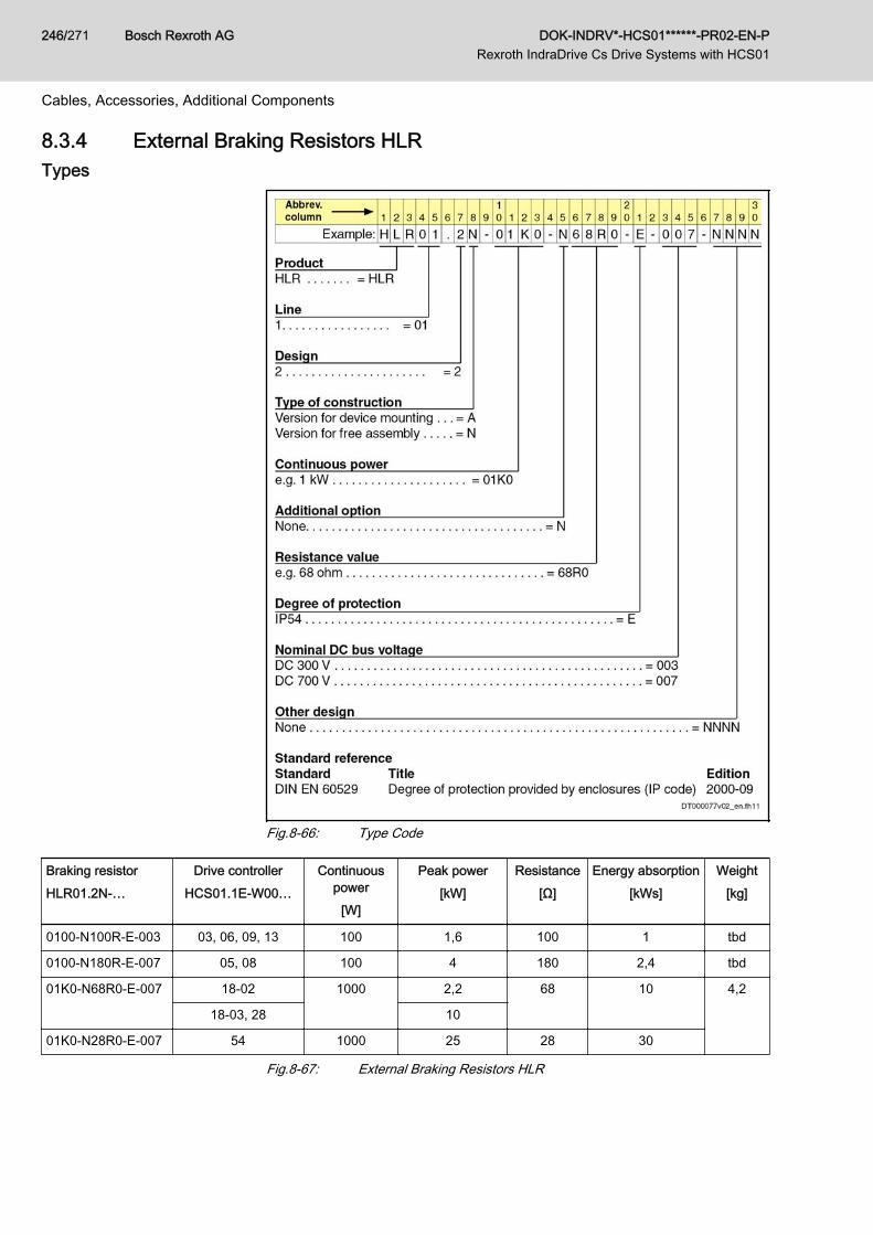
8.3.4 External Braking Resistors HLRTypes
Fig.8-66: Type Code
Braking resistorHLR01.2N-…
Drive controllerHCS01.1E-W00…
Continuouspower
[W]
Peak power[kW]
Resistance[Ω]
Energy absorption[kWs]
Weight[kg]
0100-N100R-E-003 03, 06, 09, 13 100 1,6 100 1 tbd
0100-N180R-E-007 05, 08 100 4 180 2,4 tbd
01K0-N68R0-E-007 18-02 1000 2,2 68 10 4,2
18-03, 28 10
01K0-N28R0-E-007 54 1000 25 28 30
Fig.8-67: External Braking Resistors HLR
Bosch Rexroth AG DOK-INDRV*-HCS01******-PR02-EN-P Rexroth IndraDrive Cs Drive Systems with HCS01
246/271
Cables, Accessories, Additional Components
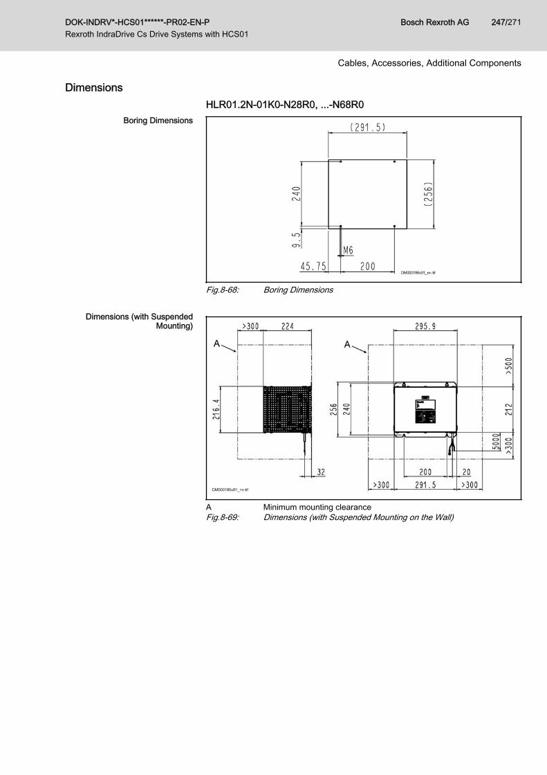
DimensionsHLR01.2N-01K0-N28R0, ...-N68R0
Boring Dimensions
Fig.8-68: Boring Dimensions
Dimensions (with SuspendedMounting)
A Minimum mounting clearanceFig.8-69: Dimensions (with Suspended Mounting on the Wall)
DOK-INDRV*-HCS01******-PR02-EN-P Rexroth IndraDrive Cs Drive Systems with HCS01
Bosch Rexroth AG 247/271
Cables, Accessories, Additional Components
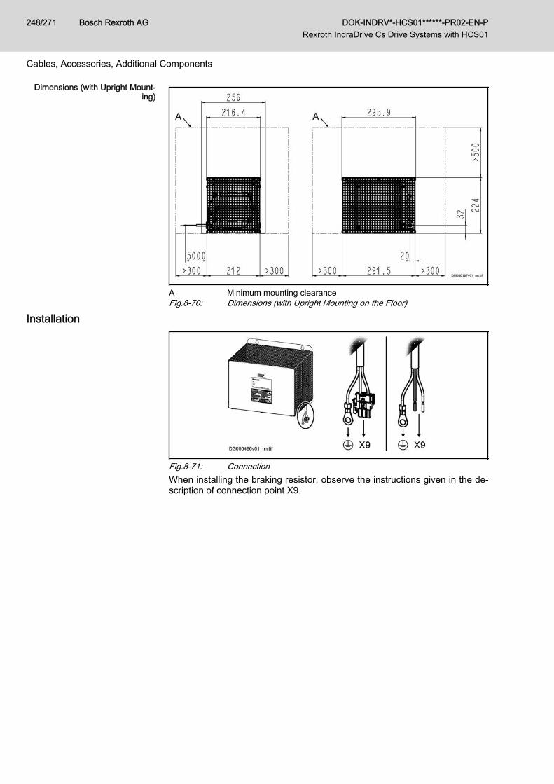
Dimensions (with Upright Mount‐ing)
A Minimum mounting clearanceFig.8-70: Dimensions (with Upright Mounting on the Floor)
Installation
Fig.8-71: ConnectionWhen installing the braking resistor, observe the instructions given in the de‐scription of connection point X9.
Bosch Rexroth AG DOK-INDRV*-HCS01******-PR02-EN-P Rexroth IndraDrive Cs Drive Systems with HCS01
248/271
Cables, Accessories, Additional Components
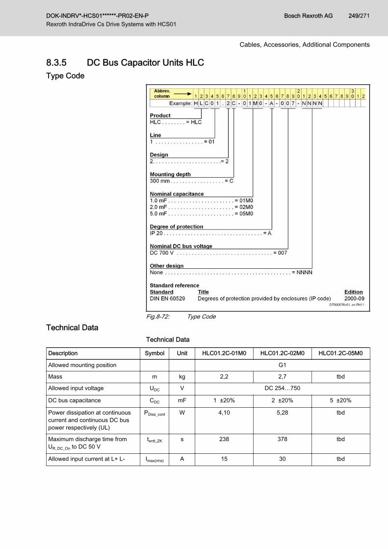
8.3.5 DC Bus Capacitor Units HLCType Code
Fig.8-72: Type Code
Technical DataTechnical Data
Description Symbol Unit HLC01.2C-01M0 HLC01.2C-02M0 HLC01.2C-05M0
Allowed mounting position G1
Mass m kg 2,2 2,7 tbd
Allowed input voltage UDC V DC 254…750
DC bus capacitance CDC mF 1 ±20% 2 ±20% 5 ±20%
Power dissipation at continuouscurrent and continuous DC buspower respectively (UL)
PDiss_cont W 4,10 5,28 tbd
Maximum discharge time fromUR_DC_On to DC 50 V
tentl_ZK s 238 378 tbd
Allowed input current at L+ L- Imax(rms) A 15 30 tbd
DOK-INDRV*-HCS01******-PR02-EN-P Rexroth IndraDrive Cs Drive Systems with HCS01
Bosch Rexroth AG 249/271
Cables, Accessories, Additional Components
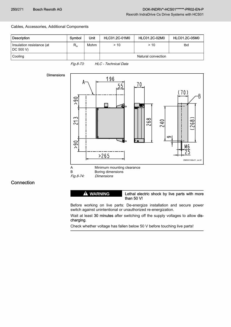
Description Symbol Unit HLC01.2C-01M0 HLC01.2C-02M0 HLC01.2C-05M0
Insulation resistance (atDC 500 V)
Ris Mohm > 10 > 10 tbd
Cooling Natural convection
Fig.8-73: HLC - Technical Data
Dimensions
A Minimum mounting clearanceB Boring dimensionsFig.8-74: Dimensions
Connection
Lethal electric shock by live parts with morethan 50 V!
WARNING
Before working on live parts: De-energize installation and secure powerswitch against unintentional or unauthorized re-energization.Wait at least 30 minutes after switching off the supply voltages to allow dis‐charging.Check whether voltage has fallen below 50 V before touching live parts!
Bosch Rexroth AG DOK-INDRV*-HCS01******-PR02-EN-P Rexroth IndraDrive Cs Drive Systems with HCS01
250/271
Cables, Accessories, Additional Components
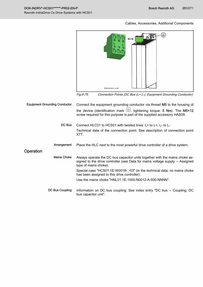
Fig.8-75: Connection Points (DC Bus (L+ L-), Equipment Grounding Conductor)
Equipment Grounding Conductor Connect the equipment grounding conductor via thread M5 to the housing of
the device (identification mark ; tightening torque: 5 Nm). The M5×12screw required for this purpose is part of the supplied accessory HAS09.
DC Bus Connect HLC01 to HCS01 with twisted lines: L+ to L+; L- to L-Technical data of the connection point: See description of connection pointX77.
Arrangement Place the HLC next to the most powerful drive controller of a drive system.
OperationMains Choke Always operate the DC bus capacitor units together with the mains choke as‐
signed to the drive controller (see Data for mains voltage supply → Assignedtype of mains choke).Special case "HCS01.1E-W0018-_-03" (in the technical data, no mains chokehas been assigned to this drive controller):Use the mains choke "HNL01.1E-1000-N0012-A-500-NNNN".
DC Bus Coupling Information on DC bus coupling: See index entry "DC bus → Coupling, DCbus capacitor unit".
DOK-INDRV*-HCS01******-PR02-EN-P Rexroth IndraDrive Cs Drive Systems with HCS01
Bosch Rexroth AG 251/271
Cables, Accessories, Additional Components

Bosch Rexroth AG DOK-INDRV*-HCS01******-PR02-EN-P Rexroth IndraDrive Cs Drive Systems with HCS01
252/271
9 Environmental Protection and Disposal9.1 Environmental Protection
Production Processes The products are made with energy- and resource-optimized production pro‐cesses which allow re-using and recycling the resulting waste. We regularlytry to replace pollutant-loaded raw materials and supplies by more environ‐ment-friendly alternatives.
No Release of Hazardous Sub‐stances
Our products do not contain any hazardous substances which may be re‐leased in the case of appropriate use. Normally, our products will not haveany negativ influences on the environment.
Significant Components Basically, our products contain the following components:Electronic devices Motors∙ steel ∙ steel∙ aluminum ∙ aluminum∙ copper ∙ copper∙ synthetic materials ∙ brass∙ electronic components and modules ∙ magnetic materials ∙ electronic components and modules
9.2 DisposalReturn of Products Our products can be returned to our premises free of charge for disposal. It is
a precondition, however, that the products are free of oil, grease or other dirt.Furthermore, the products returned for disposal must not contain any undueforeign material or foreign components.Send the products ”free domicile” to the following address: Bosch Rexroth AG Electric Drives and Controls Buergermeister-Dr.-Nebel-Strasse 2 97816 Lohr am Main, Germany
Packaging The packaging materials consist of cardboard, wood and polystyrene. Thesematerials can be recycled anywhere without any problem.For ecological reasons, please refrain from returning the empty packages tous.
Batteries and Accumulators Batteries and accumulators can be labeled with this symbol.
The symbol indicating "separate collection" for all batteries and accu‐mulators is the crossed-out wheeled bin.The end user within the EU is legally obligated to return used batteries. Out‐side the validity of the EU Directive 2006/66/EC keep the stipulated direc‐tives.Used batteries can contain hazardous substances, which can harm the envi‐ronment or the people´s health when they are improper stored or disposed of.After use, the batteries or accumulators contained in Rexroth products haveto be properly disposed of according to the country-specific collection.
Recycling Most of the products can be recycled due to their high content of metal. Inorder to recycle the metal in the best possible way, the products must be dis‐assembled into individual modules.
DOK-INDRV*-HCS01******-PR02-EN-P Rexroth IndraDrive Cs Drive Systems with HCS01
Bosch Rexroth AG 253/271
Environmental Protection and Disposal

Metals contained in electric and electronic modules can also be recycled bymeans of special separation processes.Products made of plastics can contain flame retardants. These plastic partsare labeled according to EN ISO 1043. They have to be recycled separatelyor disposed of according to the valid legal requirements.
Bosch Rexroth AG DOK-INDRV*-HCS01******-PR02-EN-P Rexroth IndraDrive Cs Drive Systems with HCS01
254/271
Environmental Protection and Disposal

10 Service and SupportOur worldwide service network provides an optimized and efficient support.Our experts offer you advice and assistance should you have any queries.You can contact us 24/7.
Service Germany Our technology-oriented Competence Center in Lohr, Germany, is responsi‐ble for all your service-related queries for electric drive and controls.Contact the Service Helpdesk & Hotline under:
Phone: +49 9352 40 5060Fax: +49 9352 18 4941E-mail: [email protected]: http://www.boschrexroth.com
Additional information on service, repair (e.g. delivery addresses) and trainingcan be found on our internet sites.
Service worldwide Outside Germany, please contact your local service office first. For hotlinenumbers, refer to the sales office addresses on the internet.
Preparing information To be able to help you more quickly and efficiently, please have the followinginformation ready:● Detailed description of malfunction and circumstances resulting in the
malfunction● Type plate name of the affected products, in particular type codes and
serial numbers● Your contact data (phone and fax number as well as your email ad‐
dress)
DOK-INDRV*-HCS01******-PR02-EN-P Rexroth IndraDrive Cs Drive Systems with HCS01
Bosch Rexroth AG 255/271
Service and Support

Bosch Rexroth AG DOK-INDRV*-HCS01******-PR02-EN-P Rexroth IndraDrive Cs Drive Systems with HCS01
256/271
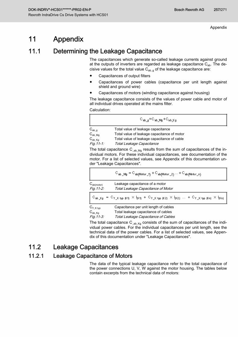
11 Appendix11.1 Determining the Leakage Capacitance
The capacitances which generate so-called leakage currents against groundat the outputs of inverters are regarded as leakage capacitance Cab. The de‐cisive values for the total value Cab_g of the leakage capacitance are:● Capacitances of output filters● Capacitances of power cables (capacitance per unit length against
shield and ground wire)● Capacitances of motors (winding capacitance against housing)The leakage capacitance consists of the values of power cable and motor ofall individual drives operated at the mains filter.Calculation:
Cab_g Total value of leakage capacitanceCab_Mg Total value of leakage capacitance of motorCab_Kg Total value of leakage capacitance of cableFig.11-1: Total Leakage CapacitanceThe total capacitance C_ab_Mg results from the sum of capacitances of the in‐dividual motors. For these individual capacitances, see documentation of themotor. For a list of selected values, see Appendix of this documentation un‐der "Leakage Capacitances".
Cab(motor) Leakage capacitance of a motorFig.11-2: Total Leakage Capacitance of Motor
CY_K typ Capacitance per unit length of cablesCab_Kg Total leakage capacitance of cablesFig.11-3: Total Leakage Capacitance of CablesThe total capacitance C_ab_Kg consists of the sum of capacitances of the indi‐vidual power cables. For the individual capacitances per unit length, see thetechnical data of the power cables. For a list of selected values, see Appen‐dix of this documentation under "Leakage Capacitances".
11.2 Leakage Capacitances11.2.1 Leakage Capacitance of Motors
The data of the typical leakage capacitance refer to the total capacitance ofthe power connections U, V, W against the motor housing. The tables belowcontain excerpts from the technical data of motors:
DOK-INDRV*-HCS01******-PR02-EN-P Rexroth IndraDrive Cs Drive Systems with HCS01
Bosch Rexroth AG 257/271
Appendix
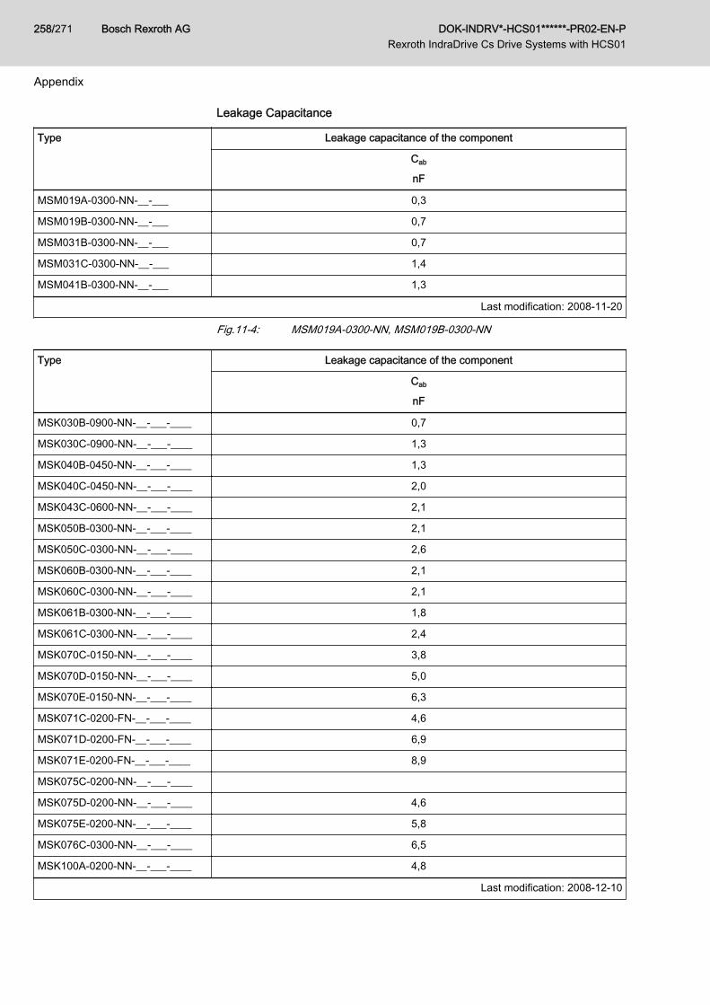
Leakage Capacitance
Type Leakage capacitance of the component
Cab
nF
MSM019A-0300-NN-__-___ 0,3
MSM019B-0300-NN-__-___ 0,7
MSM031B-0300-NN-__-___ 0,7
MSM031C-0300-NN-__-___ 1,4
MSM041B-0300-NN-__-___ 1,3
Last modification: 2008-11-20
Fig.11-4: MSM019A-0300-NN, MSM019B-0300-NN
Type Leakage capacitance of the component
Cab
nF
MSK030B-0900-NN-__-___-____ 0,7
MSK030C-0900-NN-__-___-____ 1,3
MSK040B-0450-NN-__-___-____ 1,3
MSK040C-0450-NN-__-___-____ 2,0
MSK043C-0600-NN-__-___-____ 2,1
MSK050B-0300-NN-__-___-____ 2,1
MSK050C-0300-NN-__-___-____ 2,6
MSK060B-0300-NN-__-___-____ 2,1
MSK060C-0300-NN-__-___-____ 2,1
MSK061B-0300-NN-__-___-____ 1,8
MSK061C-0300-NN-__-___-____ 2,4
MSK070C-0150-NN-__-___-____ 3,8
MSK070D-0150-NN-__-___-____ 5,0
MSK070E-0150-NN-__-___-____ 6,3
MSK071C-0200-FN-__-___-____ 4,6
MSK071D-0200-FN-__-___-____ 6,9
MSK071E-0200-FN-__-___-____ 8,9
MSK075C-0200-NN-__-___-____
MSK075D-0200-NN-__-___-____ 4,6
MSK075E-0200-NN-__-___-____ 5,8
MSK076C-0300-NN-__-___-____ 6,5
MSK100A-0200-NN-__-___-____ 4,8
Last modification: 2008-12-10
Bosch Rexroth AG DOK-INDRV*-HCS01******-PR02-EN-P Rexroth IndraDrive Cs Drive Systems with HCS01
258/271
Appendix
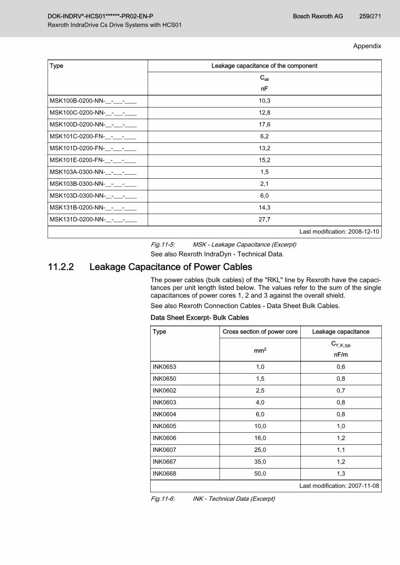
Type Leakage capacitance of the component
Cab
nF
MSK100B-0200-NN-__-___-____ 10,3
MSK100C-0200-NN-__-___-____ 12,8
MSK100D-0200-NN-__-___-____ 17,6
MSK101C-0200-FN-__-___-____ 6,2
MSK101D-0200-FN-__-___-____ 13,2
MSK101E-0200-FN-__-___-____ 15,2
MSK103A-0300-NN-__-___-____ 1,5
MSK103B-0300-NN-__-___-____ 2,1
MSK103D-0300-NN-__-___-____ 6,0
MSK131B-0200-NN-__-___-____ 14,3
MSK131D-0200-NN-__-___-____ 27,7
Last modification: 2008-12-10
Fig.11-5: MSK - Leakage Capacitance (Excerpt)See also Rexroth IndraDyn - Technical Data.
11.2.2 Leakage Capacitance of Power Cables The power cables (bulk cables) of the "RKL" line by Rexroth have the capaci‐tances per unit length listed below. The values refer to the sum of the singlecapacitances of power cores 1, 2 and 3 against the overall shield.See also Rexroth Connection Cables - Data Sheet Bulk Cables.Data Sheet Excerpt- Bulk Cables
Type Cross section of power core Leakage capacitance
mm2CY_K_typ
nF/m
INK0653 1,0 0,6
INK0650 1,5 0,8
INK0602 2,5 0,7
INK0603 4,0 0,8
INK0604 6,0 0,8
INK0605 10,0 1,0
INK0606 16,0 1,2
INK0607 25,0 1,1
INK0667 35,0 1,2
INK0668 50,0 1,3
Last modification: 2007-11-08
Fig.11-6: INK - Technical Data (Excerpt)
DOK-INDRV*-HCS01******-PR02-EN-P Rexroth IndraDrive Cs Drive Systems with HCS01
Bosch Rexroth AG 259/271
Appendix

Data Sheet Excerpt- Bulk Cables
Type Cross section of power core Leakage capacitanceCY_K_typ
mm2 nF/m
REH0800 2,5 0,2
Fig.11-7: REH - Technical Data (Excerpt)
Approximate calculation is allowed with the following values:● Cross section 1 … 6 mm2: 1 nF/m● Cross section 10 … 50 mm2: 1.2 nF/m
Bosch Rexroth AG DOK-INDRV*-HCS01******-PR02-EN-P Rexroth IndraDrive Cs Drive Systems with HCS01
260/271
Appendix
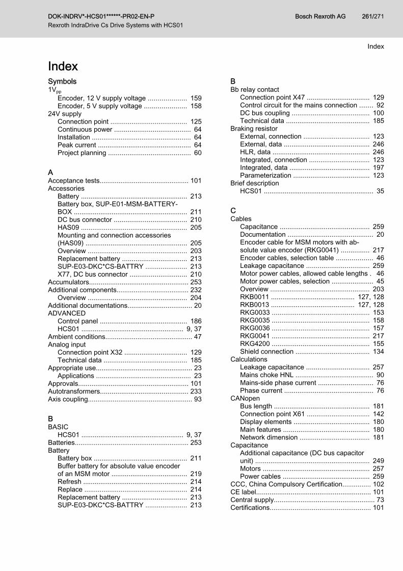
IndexSymbols1Vpp
Encoder, 12 V supply voltage .................... 159Encoder, 5 V supply voltage ...................... 158
24V supplyConnection point ........................................ 125Continuous power ........................................ 64Installation .................................................... 64Peak current ................................................. 64Project planning ........................................... 60
AAcceptance tests............................................... 101Accessories
Battery ........................................................ 213Battery box, SUP-E01-MSM-BATTERY‐BOX ............................................................ 211DC bus connector ...................................... 210HAS09 ........................................................ 205Mounting and connection accessories(HAS09) ..................................................... 205Overview .................................................... 203Replacement battery .................................. 213SUP-E03-DKC*CS-BATTRY ...................... 213X77, DC bus connector .............................. 210
Accumulators.................................................... 253Additional components...................................... 232
Overview .................................................... 204Additional documentations.................................. 20ADVANCED
Control panel .............................................. 186HCS01 ...................................................... 9, 37
Ambient conditions.............................................. 47Analog input
Connection point X32 ................................. 129Technical data ............................................ 185
Appropriate use................................................... 23Applications .................................................. 23
Approvals.......................................................... 101Autotransformers.............................................. 233Axis coupling....................................................... 93
BBASIC
HCS01 ...................................................... 9, 37Batteries............................................................ 253Battery
Battery box ................................................. 211Buffer battery for absolute value encoderof an MSM motor ........................................ 219Refresh ....................................................... 214Replace ...................................................... 214Replacement battery .................................. 213SUP-E03-DKC*CS-BATTRY ...................... 213
BBb relay contact
Connection point X47 ................................. 129Control circuit for the mains connection ....... 92DC bus coupling ......................................... 100Technical data ............................................ 185
Braking resistorExternal, connection ................................... 123External, data ............................................. 246HLR, data ................................................... 246Integrated, connection ................................ 123Integrated, data .......................................... 197Parameterization ........................................ 123
Brief descriptionHCS01 .......................................................... 35
CCables
Capacitance ............................................... 259Documentation ............................................. 20Encoder cable for MSM motors with ab‐solute value encoder (RKG0041) ............... 217Encoder cables, selection table ................... 46Leakage capacitance ................................. 259Motor power cables, allowed cable lengths . 46Motor power cables, selection ...................... 45Overview .................................................... 203RKB0011 ............................................ 127, 128RKB0013 ............................................ 127, 128RKG0033 ................................................... 153RKG0035 ................................................... 158RKG0036 ................................................... 157RKG0041 ................................................... 217RKG4200 ................................................... 155Shield connection ....................................... 134
CalculationsLeakage capacitance ................................. 257Mains choke HNL ......................................... 90Mains-side phase current ............................. 76Phase current ............................................... 76
CANopenBus length .................................................. 181Connection point X61 ................................. 142Display elements ........................................ 180Main features ............................................. 180Network dimension ..................................... 181
CapacitanceAdditional capacitance (DC bus capacitorunit) ............................................................ 249Motors ........................................................ 257Power cables .............................................. 259
CCC, China Compulsory Certification............... 102CE label............................................................ 101Central supply..................................................... 73Certifications..................................................... 101
DOK-INDRV*-HCS01******-PR02-EN-P Rexroth IndraDrive Cs Drive Systems with HCS01
Bosch Rexroth AG 261/271
Index

CCharacteristic
Fuses ........................................................... 82China Compulsory Certification (CCC)............. 102Combined encoder for SSI
Encoder, 5 V supply voltage ...................... 164Communication module
Multi-Ethernet - ET ..................................... 125PROFIBUS PB, interface ........................... 137PROFIBUS PB, signal specification ........... 180
CompatibilityWith foreign matters ..................................... 51
ComponentsCombining .................................................... 35Mounting positions ....................................... 58Supplied ....................................................... 95Supplying ..................................................... 95
Condition as supplied........................................ 105Conditions
Ambient and operating conditions ................ 47Configuration
Drive system ................................................ 35Connection
24V supply (X13) ........................................ 125Analog input (X32) ..................................... 129Bb relay contact (X47) ................................ 129Braking resistor (X9) .................................. 123Connection diagram ................................... 110Connection points, overview ...................... 111Control voltage (X13) ................................. 125DC bus (X77) ............................................. 131Digital inputs, digital output (X31) .............. 128Electrical ..................................................... 110Encoder emulation (X8) ............................. 136Equipment grounding conductor ................ 114Ground ....................................................... 135Mains ............................................................ 66Mains (X3) .................................................. 115Module bus (X47) ....................................... 129Motor (X5) .................................................. 119Motor encoder (X4) .................................... 117Motor holding brake (X6) ............................ 121Motor temperature monitoring (X6) ............ 121Multi-Ethernet (X24, X25) ........................... 125Optional encoder (X8) ................................ 135Probe .......................................................... 128PROFIBUS (X30) ....................................... 137Shield ......................................................... 134
Connection diagram.......................................... 110Connection points
HCS01, overview ....................................... 111On-board .................................................... 114Optional ...................................................... 135
Contained substancessee "Significant components" ..................... 253
Control cabinetArea A, interference-free ............................ 146
C...Control cabinet
Area B, interference-susceptible ................ 148Area C, strongly interference-susceptible . . 148Cooling ......................................................... 49Design .......................................................... 49Interference areas ...................................... 145
Control circuitFor the mains connection ............................. 92HCS01 .......................................................... 92
Control linesCable, shield connection ............................ 135
Control panelADVANCED control panel .......................... 186HAP01 .......................................................... 16Standard control panel ............................... 186Type code .................................................... 16Type plate .................................................. 107
Control voltageConnection point X13 ................................. 125Continuous power ........................................ 64Data ............................................................ 187Determining the power requirement ............. 61For drive systems ......................................... 60HCS01 ........................................................ 187Installation .................................................... 64Looping through ........................................... 66Loop-through contacts (X13) ...................... 125Peak current ................................................. 64Project planning ........................................... 60Requirements to the power supply unit ........ 64Supply with control voltage 24 V .................. 60
Converter HCS01.................................................. 7Cooling
HCS01 .......................................................... 56Corner-grounded delta mains............................. 72Coupling
Axis coupling ................................................ 93DC bus coupling ........................................... 93
C-UL-US listing................................................. 101C-UR-US listing................................................. 102
DData
Ambient conditions ....................................... 47HCS01, braking resistor (external) ............. 246HCS01, braking resistor (integrated) .......... 197HCS01, control voltage .............................. 187HCS01, cooling ............................................ 56HCS01, DC bus .......................................... 195HCS01, dimensional drawings ..................... 51HCS01, dimensions ..................................... 51HCS01, distances ........................................ 56HCS01, housing dimensions ........................ 55HCS01, insulation ........................................ 55HCS01, inverter .......................................... 199HCS01, mains voltage ............................... 189
Bosch Rexroth AG DOK-INDRV*-HCS01******-PR02-EN-P Rexroth IndraDrive Cs Drive Systems with HCS01
262/271
Index
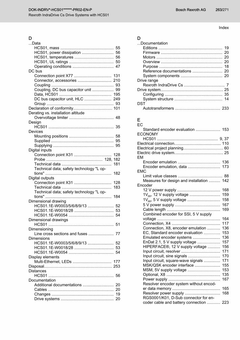
D...Data
HCS01, mass ............................................... 55HCS01, power dissipation ............................ 56HCS01, temperatures .................................. 56HCS01, UL ratings ....................................... 50Operating conditions .................................... 47
DC busConnection point X77 ................................. 131Connector, accessories .............................. 210Coupling ....................................................... 93Coupling, DC bus capacitor unit ................... 99Data, HCS01 .............................................. 195DC bus capacitor unit, HLC ........................ 249Group ........................................................... 93
Declaration of conformity.................................. 101Derating vs. installation altitude
Overvoltage limiter ....................................... 48Design
HCS01 .......................................................... 35Devices
Mounting positions ....................................... 58Supplied ....................................................... 95Supplying ..................................................... 95
Digital inputsConnection point X31 ................................. 128Probe .................................................. 128, 182Technical data ............................................ 181Technical data; safety technology "L op‐tions" .......................................................... 182
Digital outputsConnection point X31 ................................. 128Technical data ............................................ 183Technical data; safety technology "L op‐tions" .......................................................... 184
Dimensional drawingHCS01.1E-W0003/5/6/8/9/13 ....................... 52HCS01.1E-W0018/28 ................................... 53HCS01.1E-W0054 ........................................ 54
Dimensional drawingsHCS01 .......................................................... 51
DimensioningLine cross sections and fuses ...................... 77
DimensionsHCS01.1E-W0003/5/6/8/9/13 ....................... 52HCS01.1E-W0018/28 ................................... 53HCS01.1E-W0054 ........................................ 54
Display elementsMulti-Ethernet, LEDs .................................. 177
Disposal............................................................ 253Distances
HCS01 .......................................................... 56Documentation
Additional documentations ........................... 20Cables .......................................................... 20Changes ....................................................... 19Drive systems ............................................... 20
D...Documentation
Editions ........................................................ 19Firmware ...................................................... 20Motors .......................................................... 20Overview ...................................................... 20Purpose ........................................................ 18Reference documentations .......................... 20System components ..................................... 20
Drive rangeRexroth IndraDrive Cs .................................... 7
Drive system....................................................... 25Configuring ................................................... 35System structure .......................................... 14
DSTAutotransformers ........................................ 233
EEC
Standard encoder evaluation ..................... 153ECONOMY
HCS01 ...................................................... 9, 37Electrical connection......................................... 110Electrical project planning................................... 60Electric drive system........................................... 25EM
Encoder emulation ..................................... 136Encoder emulation, data ............................ 173
EMCLimit value classes ....................................... 88Measures for design and installation .......... 142
Encoder12 V power supply ...................................... 1681Vpp, 12 V supply voltage ........................... 1591Vpp, 5 V supply voltage ............................. 1585 V power supply ........................................ 167Cable length ............................................... 169Combined encoder for SSI, 5 V supplyvoltage ........................................................ 164Connection, X4 ........................................... 117Connection, X8, encoder emulation ........... 136EC, Standard encoder evaluation .............. 153Emulated encoder systems ........................ 136EnDat 2.1, 5 V supply voltage .................... 157HIPERFACE®, 12 V supply voltage ........... 156Input circuit, resolver .................................. 171Input circuit, sine signals ............................ 170Input circuit, square-wave signals .............. 171MSK/QSK encoder interface ...................... 155MSM, 5V supply voltage ............................ 153Optional, X8 ............................................... 135Power supply .............................................. 167Resolver encoder system without encod‐er data memory .......................................... 165Resolver power supply ............................... 168RGS0001/K01, D-Sub connector for en‐coder cable and battery connection ........... 223
DOK-INDRV*-HCS01******-PR02-EN-P Rexroth IndraDrive Cs Drive Systems with HCS01
Bosch Rexroth AG 263/271
Index
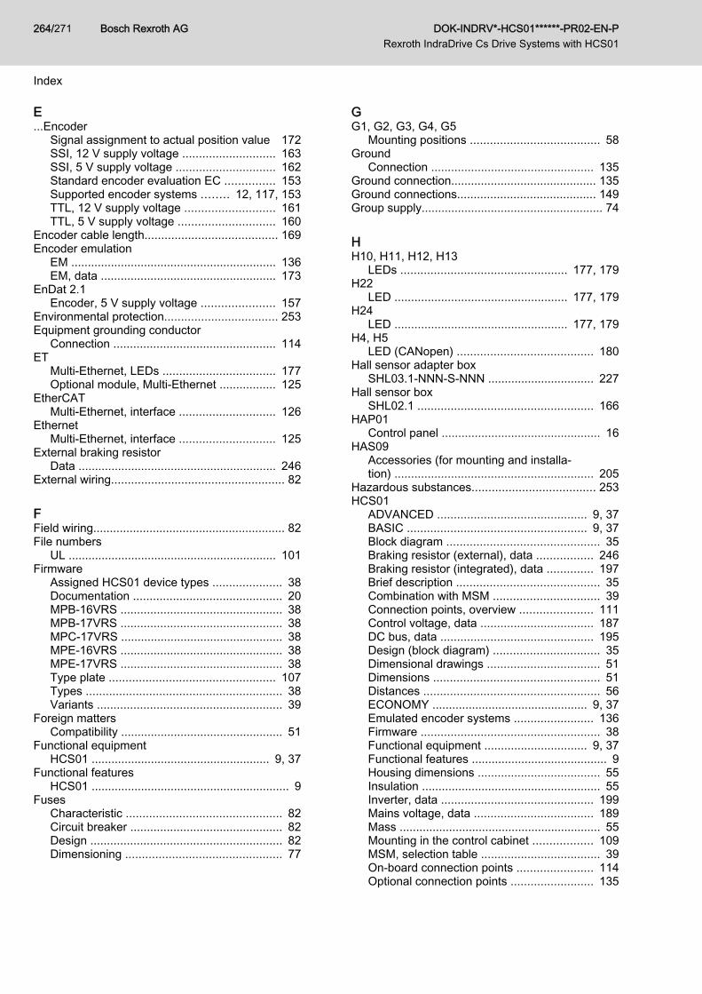
E...Encoder
Signal assignment to actual position value 172SSI, 12 V supply voltage ............................ 163SSI, 5 V supply voltage .............................. 162Standard encoder evaluation EC ............... 153Supported encoder systems ........ 12, 117, 153TTL, 12 V supply voltage ........................... 161TTL, 5 V supply voltage ............................. 160
Encoder cable length........................................ 169Encoder emulation
EM .............................................................. 136EM, data ..................................................... 173
EnDat 2.1Encoder, 5 V supply voltage ...................... 157
Environmental protection.................................. 253Equipment grounding conductor
Connection ................................................. 114ET
Multi-Ethernet, LEDs .................................. 177Optional module, Multi-Ethernet ................. 125
EtherCATMulti-Ethernet, interface ............................. 126
EthernetMulti-Ethernet, interface ............................. 125
External braking resistorData ............................................................ 246
External wiring.................................................... 82
FField wiring.......................................................... 82File numbers
UL ............................................................... 101Firmware
Assigned HCS01 device types ..................... 38Documentation ............................................. 20MPB-16VRS ................................................. 38MPB-17VRS ................................................. 38MPC-17VRS ................................................. 38MPE-16VRS ................................................. 38MPE-17VRS ................................................. 38Type plate .................................................. 107Types ........................................................... 38Variants ........................................................ 39
Foreign mattersCompatibility ................................................. 51
Functional equipmentHCS01 ...................................................... 9, 37
Functional featuresHCS01 ............................................................ 9
FusesCharacteristic ............................................... 82Circuit breaker .............................................. 82Design .......................................................... 82Dimensioning ............................................... 77
GG1, G2, G3, G4, G5
Mounting positions ....................................... 58Ground
Connection ................................................. 135Ground connection............................................ 135Ground connections.......................................... 149Group supply....................................................... 74
HH10, H11, H12, H13
LEDs .................................................. 177, 179H22
LED .................................................... 177, 179H24
LED .................................................... 177, 179H4, H5
LED (CANopen) ......................................... 180Hall sensor adapter box
SHL03.1-NNN-S-NNN ................................ 227Hall sensor box
SHL02.1 ..................................................... 166HAP01
Control panel ................................................ 16HAS09
Accessories (for mounting and installa‐tion) ............................................................ 205
Hazardous substances..................................... 253HCS01
ADVANCED ............................................. 9, 37BASIC ...................................................... 9, 37Block diagram .............................................. 35Braking resistor (external), data ................. 246Braking resistor (integrated), data .............. 197Brief description ........................................... 35Combination with MSM ................................ 39Connection points, overview ...................... 111Control voltage, data .................................. 187DC bus, data .............................................. 195Design (block diagram) ................................ 35Dimensional drawings .................................. 51Dimensions .................................................. 51Distances ..................................................... 56ECONOMY ............................................... 9, 37Emulated encoder systems ........................ 136Firmware ...................................................... 38Functional equipment ............................... 9, 37Functional features ......................................... 9Housing dimensions ..................................... 55Insulation ...................................................... 55Inverter, data .............................................. 199Mains voltage, data .................................... 189Mass ............................................................. 55Mounting in the control cabinet .................. 109MSM, selection table .................................... 39On-board connection points ....................... 114Optional connection points ......................... 135
Bosch Rexroth AG DOK-INDRV*-HCS01******-PR02-EN-P Rexroth IndraDrive Cs Drive Systems with HCS01
264/271
Index
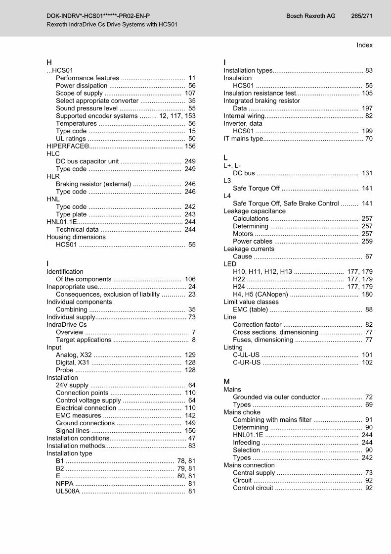
H...HCS01
Performance features ................................... 11Power dissipation ......................................... 56Scope of supply .......................................... 107Select appropriate converter ........................ 35Sound pressure level ................................... 55Supported encoder systems ........ 12, 117, 153Temperatures ............................................... 56Type code .................................................... 15UL ratings ..................................................... 50
HIPERFACE®................................................... 156HLC
DC bus capacitor unit ................................. 249Type code .................................................. 249
HLRBraking resistor (external) .......................... 246Type code .................................................. 246
HNLType code .................................................. 242Type plate .................................................. 243
HNL01.1E......................................................... 244Technical data ............................................ 244
Housing dimensionsHCS01 .......................................................... 55
IIdentification
Of the components ..................................... 106Inappropriate use................................................ 24
Consequences, exclusion of liability ............ 23Individual components
Combining .................................................... 35Individual supply................................................. 73IndraDrive Cs
Overview ........................................................ 7Target applications ......................................... 8
InputAnalog, X32 ................................................ 129Digital, X31 ................................................. 128Probe .......................................................... 128
Installation24V supply ................................................... 64Connection points ...................................... 110Control voltage supply .................................. 64Electrical connection .................................. 110EMC measures .......................................... 142Ground connections ................................... 149Signal lines ................................................. 150
Installation conditions.......................................... 47Installation methods............................................ 83Installation type
B1 ........................................................... 78, 81B2 ........................................................... 79, 81E ............................................................. 80, 81NFPA ............................................................ 81UL508A ........................................................ 81
IInstallation types................................................. 83Insulation
HCS01 .......................................................... 55Insulation resistance test.................................. 105Integrated braking resistor
Data ............................................................ 197Internal wiring...................................................... 82Inverter, data
HCS01 ........................................................ 199IT mains type...................................................... 70
LL+, L-
DC bus ....................................................... 131L3
Safe Torque Off .......................................... 141L4
Safe Torque Off, Safe Brake Control ......... 141Leakage capacitance
Calculations ................................................ 257Determining ................................................ 257Motors ........................................................ 257Power cables .............................................. 259
Leakage currentsCause ........................................................... 67
LEDH10, H11, H12, H13 ........................... 177, 179H22 ..................................................... 177, 179H24 ..................................................... 177, 179H4, H5 (CANopen) ..................................... 180
Limit value classesEMC (table) .................................................. 88
LineCorrection factor ........................................... 82Cross sections, dimensioning ...................... 77Fuses, dimensioning .................................... 77
ListingC-UL-US ..................................................... 101C-UR-US .................................................... 102
MMains
Grounded via outer conductor ...................... 72Types ........................................................... 69
Mains chokeCombining with mains filter .......................... 91Determining .................................................. 90HNL01.1E ................................................... 244Infeeding .................................................... 244Selection ...................................................... 90Types ......................................................... 242
Mains connectionCentral supply .............................................. 73Circuit ........................................................... 92Control circuit ............................................... 92
DOK-INDRV*-HCS01******-PR02-EN-P Rexroth IndraDrive Cs Drive Systems with HCS01
Bosch Rexroth AG 265/271
Index
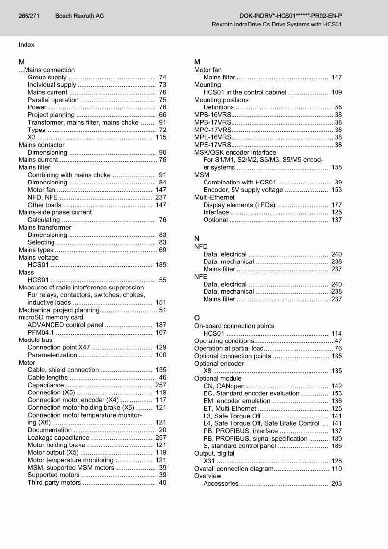
M...Mains connection
Group supply ................................................ 74Individual supply ........................................... 73Mains current ............................................... 76Parallel operation ......................................... 75Power ........................................................... 76Project planning ........................................... 66Transformer, mains filter, mains choke ........ 91Types ........................................................... 72X3 ............................................................... 115
Mains contactorDimensioning ............................................... 90
Mains current...................................................... 76Mains filter
Combining with mains choke ....................... 91Dimensioning ............................................... 84Motor fan .................................................... 147NFD, NFE ................................................... 237Other loads ................................................. 147
Mains-side phase currentCalculating ................................................... 76
Mains transformerDimensioning ............................................... 83Selecting ...................................................... 83
Mains types......................................................... 69Mains voltage
HCS01 ........................................................ 189Mass
HCS01 .......................................................... 55Measures of radio interference suppression
For relays, contactors, switches, chokes,inductive loads ........................................... 151
Mechanical project planning............................... 51microSD memory card
ADVANCED control panel .......................... 187PFM04.1 ..................................................... 107
Module busConnection point X47 ................................. 129Parameterization ........................................ 100
MotorCable, shield connection ............................ 135Cable lengths ............................................... 46Capacitance ............................................... 257Connection (X5) ......................................... 119Connection motor encoder (X4) ................. 117Connection motor holding brake (X6) ........ 121Connection motor temperature monitor‐ing (X6) ....................................................... 121Documentation ............................................. 20Leakage capacitance ................................. 257Motor holding brake ................................... 121Motor output (X5) ....................................... 119Motor temperature monitoring .................... 121MSM, supported MSM motors ..................... 39Supported motors ......................................... 39Third-party motors ........................................ 40
MMotor fan
Mains filter .................................................. 147Mounting
HCS01 in the control cabinet ..................... 109Mounting positions
Definitions .................................................... 58MPB-16VRS........................................................ 38MPB-17VRS........................................................ 38MPC-17VRS....................................................... 38MPE-16VRS........................................................ 38MPE-17VRS........................................................ 38MSK/QSK encoder interface
For S1/M1, S2/M2, S3/M3, S5/M5 encod‐er systems .................................................. 155
MSMCombination with HCS01 ............................. 39Encoder, 5V supply voltage ....................... 153
Multi-EthernetDisplay elements (LEDs) ............................ 177Interface ..................................................... 125Optional ...................................................... 137
NNFD
Data, electrical ........................................... 240Data, mechanical ....................................... 238Mains filter .................................................. 237
NFEData, electrical ........................................... 240Data, mechanical ....................................... 238Mains filter .................................................. 237
OOn-board connection points
HCS01 ........................................................ 114Operating conditions........................................... 47Operation at partial load...................................... 76Optional connection points................................ 135Optional encoder
X8 ............................................................... 135Optional module
CN, CANopen ............................................ 142EC, Standard encoder evaluation .............. 153EM, encoder emulation .............................. 136ET, Multi-Ethernet ...................................... 125L3, Safe Torque Off .................................... 141L4, Safe Torque Off, Safe Brake Control . . . 141PB, PROFIBUS, interface .......................... 137PB, PROFIBUS, signal specification .......... 180S, standard control panel ........................... 186
Output, digitalX31 ............................................................. 128
Overall connection diagram.............................. 110Overview
Accessories ................................................ 203
Bosch Rexroth AG DOK-INDRV*-HCS01******-PR02-EN-P Rexroth IndraDrive Cs Drive Systems with HCS01
266/271
Index
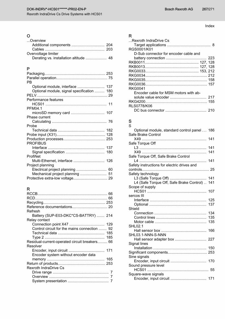
O...Overview
Additional components ............................... 204Cables ........................................................ 203
Overvoltage limiterDerating vs. installation altitude ................... 48
PPackaging......................................................... 253Parallel operation................................................ 75PB
Optional module, interface ......................... 137Optional module, signal specification ......... 180
PELV................................................................... 29Performance features
HCS01 .......................................................... 11PFM04.1
microSD memory card ............................... 107Phase current
Calculating ................................................... 76Probe
Technical data ............................................ 182Probe input (X31).............................................. 128Production processes....................................... 253PROFIBUS
Interface ..................................................... 137Signal specification .................................... 180
ProfiNetMulti-Ethernet, interface ............................. 126
Project planningElectrical project planning ............................ 60Mechanical project planning ......................... 51
Protective extra-low voltage................................ 29
RRCCB.................................................................. 66RCD.................................................................... 66Recycling.......................................................... 253Reference documentations................................. 20Refresh
Battery (SUP-E03-DKC*CS-BATTRY) ....... 214Relay contact
Connection point X47 ................................. 129Control circuit for the mains connection ....... 92Technical data ............................................ 185Type 2 ........................................................ 185
Residual-current-operated circuit breakers......... 66Resolver
Encoder, input circuit .................................. 171Encoder system without encoder datamemory ...................................................... 165
Return of products............................................ 253Rexroth IndraDrive Cs
Drive range ..................................................... 7Overview ........................................................ 7System presentation ...................................... 7
R...Rexroth IndraDrive Cs
Target applications ......................................... 8RGS0001/K01
D-Sub connector for encoder cable andbattery connection ...................................... 223
RKB0011................................................... 127, 128RKB0013................................................... 127, 128RKG0033.................................................. 153, 212RKG0034.......................................................... 212RKG0035.......................................................... 158RKG0036.......................................................... 157RKG0041
Encoder cable for MSM motors with ab‐solute value encoder .................................. 217
RKG4200.......................................................... 155RLS0778/K06
DC bus connector ...................................... 210
SS
Optional module, standard control panel . . . 186Safe Brake Control
X49 ............................................................. 141Safe Torque Off
L3 ............................................................... 141X49 ............................................................. 141
Safe Torque Off, Safe Brake ControlL4 ............................................................... 141
Safety instructions for electric drives andcontrols............................................................... 25Safety technology
L3 (Safe Torque Off) .................................. 141L4 (Safe Torque Off, Safe Brake Control) . . 141
Scope of supplyHCS01 ........................................................ 107
sercos IIIInterface ..................................................... 125Optional ...................................................... 137
ShieldConnection ................................................. 134Control lines ............................................... 135Motor cable ................................................ 135
SHL02.1Hall sensor box .......................................... 166
SHL03.1-NNN-S-NNNHall sensor adapter box ............................. 227
Signal linesInstallation .................................................. 150
Significant components..................................... 253Sine signals
Encoder, input circuit .................................. 170Sound pressure level
HCS01 .......................................................... 55Square-wave signals
Encoder, input circuit .................................. 171
DOK-INDRV*-HCS01******-PR02-EN-P Rexroth IndraDrive Cs Drive Systems with HCS01
Bosch Rexroth AG 267/271
Index
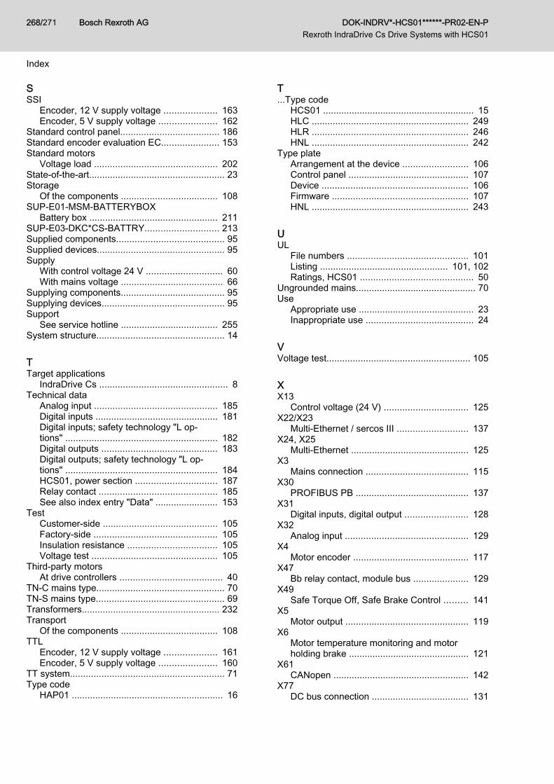
SSSI
Encoder, 12 V supply voltage .................... 163Encoder, 5 V supply voltage ...................... 162
Standard control panel...................................... 186Standard encoder evaluation EC...................... 153Standard motors
Voltage load ............................................... 202State-of-the-art.................................................... 23Storage
Of the components ..................................... 108SUP-E01-MSM-BATTERYBOX
Battery box ................................................. 211SUP-E03-DKC*CS-BATTRY............................ 213Supplied components......................................... 95Supplied devices................................................. 95Supply
With control voltage 24 V ............................. 60With mains voltage ....................................... 66
Supplying components........................................ 95Supplying devices............................................... 95Support
See service hotline ..................................... 255System structure................................................. 14
TTarget applications
IndraDrive Cs ................................................. 8Technical data
Analog input ............................................... 185Digital inputs ............................................... 181Digital inputs; safety technology "L op‐tions" .......................................................... 182Digital outputs ............................................ 183Digital outputs; safety technology "L op‐tions" .......................................................... 184HCS01, power section ............................... 187Relay contact ............................................. 185See also index entry "Data" ........................ 153
TestCustomer-side ............................................ 105Factory-side ............................................... 105Insulation resistance .................................. 105Voltage test ................................................ 105
Third-party motorsAt drive controllers ....................................... 40
TN-C mains type................................................. 70TN-S mains type................................................. 69Transformers..................................................... 232Transport
Of the components ..................................... 108TTL
Encoder, 12 V supply voltage .................... 161Encoder, 5 V supply voltage ...................... 160
TT system........................................................... 71Type code
HAP01 .......................................................... 16
T...Type code
HCS01 .......................................................... 15HLC ............................................................ 249HLR ............................................................ 246HNL ............................................................ 242
Type plateArrangement at the device ......................... 106Control panel .............................................. 107Device ........................................................ 106Firmware .................................................... 107HNL ............................................................ 243
UUL
File numbers .............................................. 101Listing ................................................. 101, 102Ratings, HCS01 ........................................... 50
Ungrounded mains.............................................. 70Use
Appropriate use ............................................ 23Inappropriate use ......................................... 24
VVoltage test....................................................... 105
XX13
Control voltage (24 V) ................................ 125X22/X23
Multi-Ethernet / sercos III ........................... 137X24, X25
Multi-Ethernet ............................................. 125X3
Mains connection ....................................... 115X30
PROFIBUS PB ........................................... 137X31
Digital inputs, digital output ........................ 128X32
Analog input ............................................... 129X4
Motor encoder ............................................ 117X47
Bb relay contact, module bus ..................... 129X49
Safe Torque Off, Safe Brake Control ......... 141X5
Motor output ............................................... 119X6
Motor temperature monitoring and motorholding brake .............................................. 121
X61CANopen .................................................... 142
X77DC bus connection ..................................... 131
Bosch Rexroth AG DOK-INDRV*-HCS01******-PR02-EN-P Rexroth IndraDrive Cs Drive Systems with HCS01
268/271
Index

X...X77
DC bus connector ...................................... 210X8
Encoder emulation ..................................... 136
X...X8
Optional encoder ........................................ 135X9
Braking resistor .......................................... 123
DOK-INDRV*-HCS01******-PR02-EN-P Rexroth IndraDrive Cs Drive Systems with HCS01
Bosch Rexroth AG 269/271
Index

Bosch Rexroth AG DOK-INDRV*-HCS01******-PR02-EN-P Rexroth IndraDrive Cs Drive Systems with HCS01
270/271

Notes
DOK-INDRV*-HCS01******-PR02-EN-P Rexroth IndraDrive Cs Drive Systems with HCS01
Bosch Rexroth AG 271/271
DOK-INDRV*-HCS01******-PR02-EN-PR911322210
Bosch Rexroth AG Electric Drives and Controls P.O. Box 13 57 97803 Lohr, Germany Bgm.-Dr.-Nebel-Str. 2 97816 Lohr, Germany Tel. +49 9352 18 0 Fax +49 9352 18 8400 www.boschrexroth.com/electrics