Embed Size (px)
Citation preview

5 IV April 2017

www.ijraset.com Volume 5 Issue IV, April 2017 IC Value: 45.98 ISSN: 2321-9653
International Journal for Research in Applied Science & Engineering Technology (IJRASET)
©IJRASET: All Rights are Reserved 1700
Weight Reduction and Strengthening Of RC Beam Using CFRP and GFRP Layers by ANSYS
15.0 V. S. Bhadauria1, M. K. Trivedi2
1PG student, 2Professor, Department of Civil Engineering Madhav Institute of Technology & Science, Gwalior, Madhya Pradesh, India
Abstract: The current paper focuses on the study of RC beam with FRP as external layers. CFRP and GFRP as FRP materials are considered during the current work to study their behaviour on the deformation, strain and weight by means of ANSYS 15.0. Different geometries of concrete beam are drawn having numbers of laminates of FRP, considering all the geometries have outer dimensions. Effect of number of layers is also correlated with control beam having no FRP layers. The outcomes specify that total deformation decreases after giving FRP layers within the reinforced concrete. Total of maximum strain developed into the beam is also appeared to be decreases with accumulation of FRP layers and beam having three FRP layers shows minimum maximum strain. Among the Two FRP materials (CFRP and GFRP) considered CFRP shows better results correlated to the GFRP. Results also reveal that with increment in the load applied, beam through CFRP as external layer shows better performance correlated to all other cases. Keywords: CFRP, GFRP, Deformation, Strain, Weight, Reinforced Beam, ANSYS 15.0.
I. INTRODUCTION Maintenance of concrete members with covering FRP sheets grant an extra cost-effective and precisely superior substitute to the usual techniques in several situations as of its offers huge strength, less weight, corrosion resistance, fatigue resistance, simple and swift installation and slightest change in infrastructural geometry. In addition, FRP manufacturing offers an exclusive chance intended in favor of the improvement of shapes as well as forms that would be difficult or impractical by the usual materials. Even if the fibers used in FRP are quite costly correlated with conventional strengthening materials, labor and equipment costs to establish FRP methods are often lower. FRP methods could moreover be useful in areas with limited contact where usual techniques would be impossible. Retnam et. al. [2] they observe material properties of GFRP and CFRP material. Raj [3] studied examination for increase the flexural and shear ability of RC beam by GFRP and CFRP. Musmar et. al. [4] intends to revise the action of RC beams as subjected to oblique loading. More et. al. [5] paper informs us about the flexural performance of AFRP strengthen reinforced concrete. Antony et. al. [6] investigated the external work on the strength parameter of concrete beam by ANSYS. Rao et. al. [7] worked on the assessment of act of ordinary concrete and fibre reinforced regular. Vasudevan et. al. [8] worked on FE designing of RC beams by means of ANSYS 12.0. Sobuz et. al [9] investigational the flexural act of RC beams strengthened with CFRP laminates. Pannirselvam et. al [10] work objective be to assess the structural performance of RC beams with exteriorly bonded FRP strengthening. Correia et. al. [11] analyzed on structural presentation of GFRP hybrid beam. Subramani et. al. [12] worked on a systematic study to observe the act of concrete beams bonded through strengthened Glass Fiber-Reinforced Polymer (GFRP).
II. OBJECTIVE & METHODOLOGY To do this FE software like ANSYS be utilized. Design and dimensions of the beam are taken from literature. After that appropriate boundary conditions like load acting on the beam and fixed support are applied. Then the consequences of FRP layers (GFRP and CFRP) are studied in the ANSYS software by giving added layers on concrete beam. Study of weight assessment is also conducted.
III. MATERIALS All the properties are taken from literature I reviewed.
TABLE I CONCRETE PROPERTIES Properties Values found in laboratory Density (kg/m3) 2300

www.ijraset.com Volume 5 Issue IV, April 2017 IC Value: 45.98 ISSN: 2321-9653
International Journal for Research in Applied Science & Engineering Technology (IJRASET)
1701
Compressive strength (MPa) 36.0 Modulus of elasticity (GPa) 28.6 Ultimate/Splitting tensile strength (MPa) 2.95 Poisson ratio 0.18
TABLE II STEEL PROPERTIES Reinforcement type Yield strength (MPa) Modulus of elasticity (GPa) Tension, T10 482 195 Compression, T6 470 186 Shear, R6 215 200
TABLE IV CFRP & GFRP LAMINATES PROPERTIES Values Property CFRP GFRP Sheet form Uni-directional roving Uni-directional roving Yield strength (MPa) 1315 1400 Modulus of Elasticity (GPa)
165 45
Elongation at ultimate (%)
2.15 3.1
Design thickness (mm) 1.2 1.2 Tensile strength (MPa) 1685 1410 Density (Kg/m3) 1600 2100 Poisson ratio 0.28 0.28
IV. MODELING Figure 1 below displays the exaggerated look of the bottom side where the FRP as external layers has given. Figure 2 displays the Cross-sectional and 3D look of the control beam. Figure 3 displays the meshing in geometry of beam. Table 5 displays the dimensions of the all the four geometries.
Fig. 1 Exaggerated view of the control beam and beam with FRP layers
Fig. 2 Cross-sectional and 3D look of the control beam

www.ijraset.com Volume 5 Issue IV, April 2017 IC Value: 45.98 ISSN: 2321-9653
International Journal for Research in Applied Science & Engineering Technology (IJRASET)
1702
Fig. 3 Meshing in geometry of beam
TABLE V DIMENSIONS OF GEOMETRIES DRAWN
Dimensions RB (control) 1L- FRP 2L-FRP 3L-FRP
Length 1900 1900 1900 1900
Height 200 198.8+1.2 197.6+1.2+1.2 196.4+1.2+1.2+1.2
Width 150 150 150 150
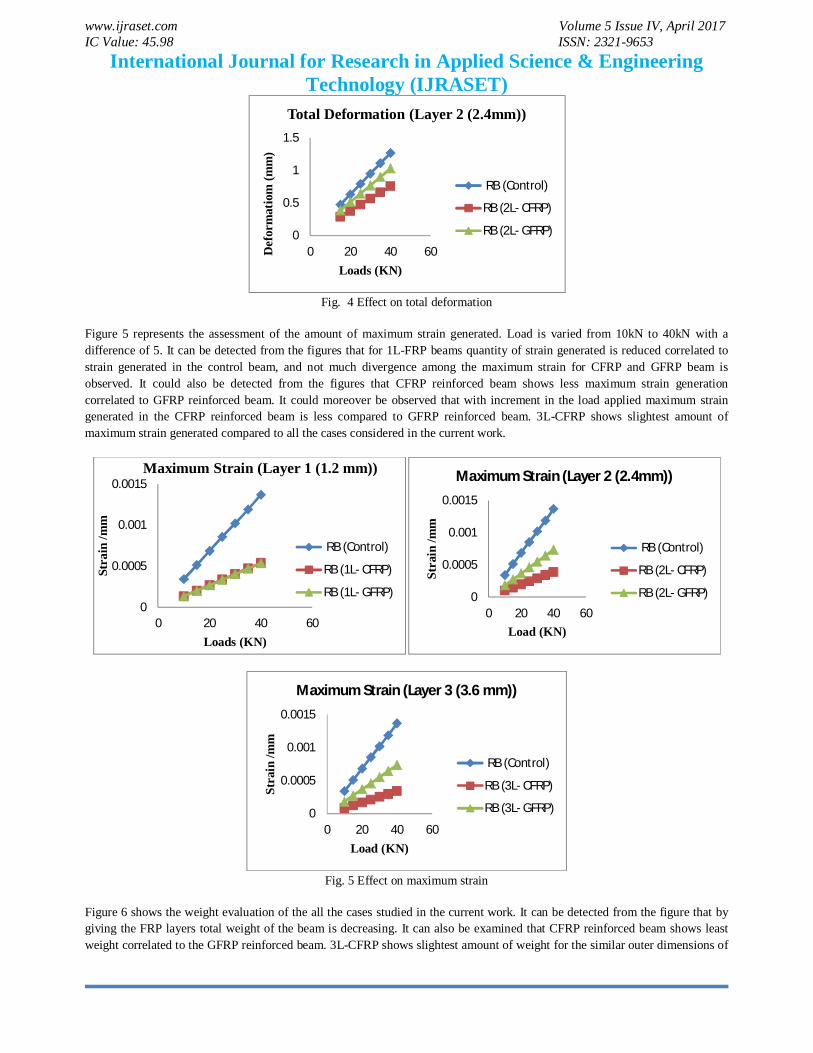
V. TEST RESULTS AND DISCUSSION Figure 4 represents the assessment of the amount of total deformation generated among the different beams considered in the current work. Load is varied from 10kN to 40kN by a difference of 5. It could be detected from the figures that there is not much deviation amid the total deformation generated for 1L-FRP beams correlated to control beam, but for 2L-FRP and 3L-FRP beams distinction among the deformations generated could be easily observed. It can also be monitored as of the figures that CFRP reinforced beam shows less deformation generation as considered to GFRP reinforced beam. It can also be detected that with increment in the load applied total deformation generated in the CFRP reinforced beam is less correlated to GFRP reinforced beam. 3L-CFRP shows slightest amount of total deformation generated contemplated to all the cases considered in the current work.
012
0 20 40 60
Def
orm
atio
n (m
m)
Load (KN)
Total Deformation (Layer 1 (1.2mm))
RB (Control)
RB (1L- CFRP)
RB (1L- GFRP)
0
0.5
1
1.5
0 20 40 60
Def
orm
atio
n (m
m)
Load (KN)
Total Deformation (Layer 3 (3.6 mm))
RB (Control)
RB (3L- CFRP)
RB (3L- GFRP)
www.ijraset.com Volume 5 Issue IV, April 2017 IC Value: 45.98 ISSN: 2321-9653
International Journal for Research in Applied Science & Engineering Technology (IJRASET)
1703
Fig. 4 Effect on total deformation
Figure 5 represents the assessment of the amount of maximum strain generated. Load is varied from 10kN to 40kN with a difference of 5. It can be detected from the figures that for 1L-FRP beams quantity of strain generated is reduced correlated to strain generated in the control beam, and not much divergence among the maximum strain for CFRP and GFRP beam is observed. It could also be detected from the figures that CFRP reinforced beam shows less maximum strain generation correlated to GFRP reinforced beam. It could moreover be observed that with increment in the load applied maximum strain generated in the CFRP reinforced beam is less compared to GFRP reinforced beam. 3L-CFRP shows slightest amount of maximum strain generated compared to all the cases considered in the current work.
Fig. 5 Effect on maximum strain
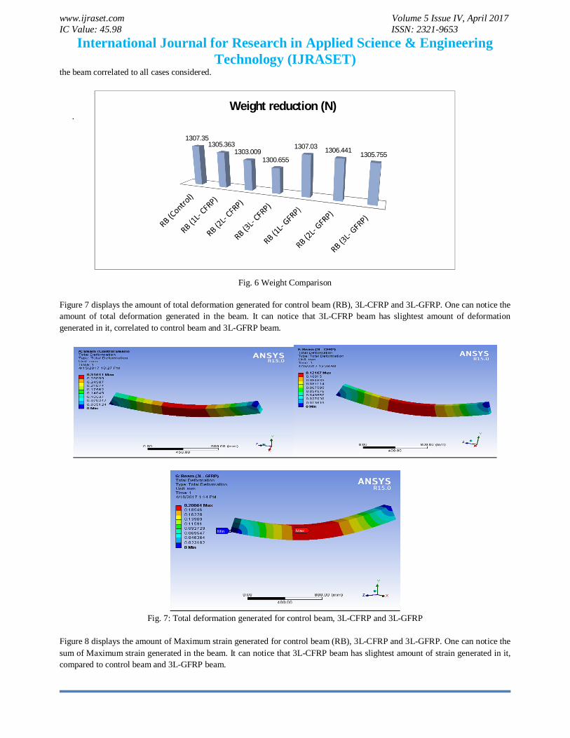
Figure 6 shows the weight evaluation of the all the cases studied in the current work. It can be detected from the figure that by giving the FRP layers total weight of the beam is decreasing. It can also be examined that CFRP reinforced beam shows least weight correlated to the GFRP reinforced beam. 3L-CFRP shows slightest amount of weight for the similar outer dimensions of
0
0.5
1
1.5
0 20 40 60Def
orm
atio
m (m
m)
Loads (KN)
Total Deformation (Layer 2 (2.4mm))
RB (Control)
RB (2L- CFRP)
RB (2L- GFRP)
0
0.0005
0.001
0.0015
0 20 40 60
Stra
in /m
m
Loads (KN)
Maximum Strain (Layer 1 (1.2 mm))
RB (Control)
RB (1L- CFRP)
RB (1L- GFRP) 0
0.0005
0.001
0.0015
0 20 40 60
Stra
in /m
m
Load (KN)
Maximum Strain (Layer 2 (2.4mm))
RB (Control)
RB (2L- CFRP)
RB (2L- GFRP)
0
0.0005
0.001
0.0015
0 20 40 60
Stra
in /m
m
Load (KN)
Maximum Strain (Layer 3 (3.6 mm))
RB (Control)
RB (3L- CFRP)
RB (3L- GFRP)
www.ijraset.com Volume 5 Issue IV, April 2017 IC Value: 45.98 ISSN: 2321-9653
International Journal for Research in Applied Science & Engineering Technology (IJRASET)
1704
the beam correlated to all cases considered.
.
Fig. 6 Weight Comparison
Figure 7 displays the amount of total deformation generated for control beam (RB), 3L-CFRP and 3L-GFRP. One can notice the amount of total deformation generated in the beam. It can notice that 3L-CFRP beam has slightest amount of deformation generated in it, correlated to control beam and 3L-GFRP beam.
Fig. 7: Total deformation generated for control beam, 3L-CFRP and 3L-GFRP
Figure 8 displays the amount of Maximum strain generated for control beam (RB), 3L-CFRP and 3L-GFRP. One can notice the sum of Maximum strain generated in the beam. It can notice that 3L-CFRP beam has slightest amount of strain generated in it, compared to control beam and 3L-GFRP beam.
1307.35 1305.363
1303.009 1300.655
1307.03 1306.441 1305.755
Weight reduction (N)

www.ijraset.com Volume 5 Issue IV, April 2017 IC Value: 45.98 ISSN: 2321-9653
International Journal for Research in Applied Science & Engineering Technology (IJRASET)
1705
Fig. 8: Maximum strain for Control beam, 3L-CFRP and 3L-GFRP
VI. CONCLUSIONS Based on the ANSYS 15.0 WORKBENCH test results, the subsequent conclusion can be made A. CFRP laminates can be used effectively to strengthen the RC beams. Varying from width of FRP layer it reduced the
deflection of beam between 8% - 62%. B. CFRP layer it reduced the equivalent elastic strain between 61% -76%. C. GFRP layers also reduced the deflection between 3% - 35%, but less as correlated to CFRP laminates. D. 1L-GFRP results in the strain reduction of approximately 42%, but for 2L-GFRP it lessens to 42% because of low elastic
modulus as compared to CFRP laminates. E. Replacement of concrete by CFRP and GFRP layer results in reduction of weight. F. In common, CFRP layers are best as compared to GFRP laminates for the strengthening of RC member.
REFERENCES [1] V. S. Pawar, P. M. Pawar, “Modelling of Flexural Failure in Reinforced Concrete Beams as Under, Balanced and Over-reinforced” International
Journal of Engineering Trends and Technology, Volume 36, June 2016. [2] B. Stanly Jones Retnam et al, 2015, Analysis of mechanical properties of glass and carbon fiber reinforced polymer material, International Journal of
Applied Engineering Research ISSN 0973-4562 Volume 10, Number 11 (2015) [3] D.Preetam Prem Raj, “SHEAR AND FLEXURAL STRENGTHENING IN RC BEAMS USING FRP” International Journal of Science, Technology &
Management, Volume No.04, Issue No. 05, May 2015. [4] M. A. Musmar et al, 2014, NONLINEAR FINITE ELEMENT ANALYSIS OF SHALLOW REINFORCED CONCRETE BEAMS USING SOLID65
ELEMENT, ARPN Journal of Engineering and Applied Sciences. [5] Rameshkumar U More, et al, 2014, FLEXURAL BEHAVIOURAL STUDY ON RC BEAM WITH EXTERNALLY BONDED ARAMID FIBER
REINFORCED POLYMER, IJRET: International Journal of Research in Engineering and Technology. [6] N. K. Antony, Ramadass S, Jayasree Ramanujan, “Parametric study on the shear strength of concrete deep beam using ANSYS” American Journal of
Engineering Research (AJER), e-ISSN : 2320-0847, Volume-4 pp-51-59, 2013. [7] K.Srinivasa Rao, S.Rakesh kumar, A.Laxmi Narayana, “Comparison of performance of standard reinforced concrete and fibre reinforced concrete exposed
to elevated temperature” American Journal of Engineering Research, Vol. 02, issue. 03, 2013 [8] G. Vasudevan, S. Kothandaraman, S. Azhagarsamy,“ Study on non-linear flexural behaviour of reinforced concrete beams using Ansys by discrete
reinforcement modeling”, Vol. 45, No. 2, March, 2013. [9] Habibur Rahman Sobuz et al, 2011, Use of carbon fiber laminates for strengthening reinforced concrete beams in bending, INTERNATIONAL
JOURNAL OF CIVIL AND STRUCTURAL ENGINEERING Volume 2, No 1, 2011. [10] N. Pannirselvam, V. Nagaradjane
and K. Chandramouli, “ Strength behavior of fibre reinforced polymer strengthened beam” ARPN Journal of
Engineering and Applied Sciences, VOL. 4, NO. 9, NOVEMBER 2009. [11] J.R. Correia, F.A. Branco, J.G. Ferreira, “STRUCTURAL BEHAVIOUR OF GFRP-CONCRETE HYBRID BEAMS” Composites in Construction 2005-
3rd International Conference, Lyon France, July 11-13, 2005. [12] T.Subramani et al,2015, “Analytical Investigation of bonded Glass Fibre Reinforced Polymer Sheets with Reinforced Concrete Beam using Ansys”
International Journal Application or Innovation in Engineering & Management (IJAIEM) Volume 4, Issue 5, May 2015