Embed Size (px)
Citation preview

2 VIII August 2014

www.ijraset.com Vol. 2 Issue VIII, August 2014
ISSN: 2321-9653
I N T E R N A T I O N A L J O U R N A L F O R R E S E A R C H I N A P P L I E D S C I E N C EAN D E N G I N E E R I N G T E C H N O L O G Y (I J R A S E T)
Page 1
Power Quality Improvement In Weak Grids With
Three Phase Three Leg Active Power Conditioner
Putta Praveen Kumar #1, Savarapu Chandra Shekar *2, 1PG Scholar, Dept of Electrical and Electronics Engineering, Anurag Engineering College, Kodad, JNTU Hyd, INDIA2Assoc. Prof. & HOD, Dept of Electrical and Electronics Engineering, Anurag Engineering College, Kodad, JNTU Hyd,
INDIA
Abstract—This paper presents a three phase three leg active power conditioner to improve power quality based on renewable energy. A micro-grid is a weak electrical grid, which can be easily subject to disturbances because it includes a variety of intermittent power sources, single-phase, three-phase and nonlinear loads, which can have a dynamic impact on power quality. The unbalance and the harmonic components in current and voltage waveforms are the most important among these. In this paper, the topology and the control strategy of Active Power Conditioner (APC) have been investigated in order to improve the operation of a micro-grid. The APC topology presented in this paper act as an interface between renewable energy sources and the AC bus of a micro-grid. They also use an improved control strategy, which makes possible to inject energy in the micro-grid, compensate the current harmonics and correct the power factor. Moreover, the proposed control strategy allows the line current at the point of common coupling (PCC) to be balanced and sinusoidal even when the load is unbalanced. Consequently, the voltage at the PCC becomes balanced. The simulation results are grouped and presented according to the following power quality indicators: THD (Total Harmonic Distortion), power factor and unbalanced load.
Keywords— Active power conditioner, micro-grids, renewable energy, current control, power quality.
I. INTRODUCTION
A micro-grid can be defined as a portion of an electric power distribution system that is located downstream of the distribution substation and includes a variety of distributed generation and storage systems and various loads. A micro-grid is different from a main grid system, which can be considered as an unlimited power so that load variations do not affect the stability of the system. On the contrary, in a micro-grid, large and sudden changes in the load may result in voltage transient of large magnitudes in the AC bus. Moreover, the proliferation of switching power converters and nonlinear loads with large rated power can increase the contamination level in voltage and current waveforms in a micro-grid, forcing to improve the compensation
characteristics required to satisfy more stringent harmonics standards.
The traditional method of current Harmonics reduction involves passive LC filters, which are its simplicity and low cost. These have several drawbacks such as large size, tuning and risk of resonance problems of current harmonics. The 3-leg APC can solve problems of current harmonics, reactive power, load current balancing and excessive neutral current.The shunt APC based on voltage source inverter is solution to harmonic current problems.
A possible solution to overcome the above mentioned drawback is to use the APC as a power interface between the renewable energy sources and the AC bus of the micro grids as shown in Fig. 1.

www.ijraset.com Vol. 2 Issue VIII, August 2014
ISSN: 2321-9653
I N T E R N A T I O N A L J O U R N A L F O R R E S E A R C H I N A P P L I E D S C I E N C EAN D E N G I N E E R I N G T E C H N O L O G Y (I J R A S E T)
Page 259
Fig. 1 APC for microgrid applications
The APC has proved to be an important alternative to compensate current and voltage disturbances in power distribution systems [1], [2]. Different APC topologies have been presented in the technical literature [3], but most of them are not adapted for micro-grids applications.
This paper presents an APC used to improve the power quality in a microgrid. The attention will be mainly focused on the innovative control strategy, which allows injecting energy in the microgrid, compensating the current harmonics, correcting the power factor and balancing the supply voltage at the PCC. The validity of the control strategy has been proved through many simulation tests using Sim PowerSystems from MATLAB.
II. PHOTOVOLTAIC TECHNOLOGY
A photovoltaic (PV) system directly converts sunlight into electricity. The basic device of PV system is the PV cell. A PV system consists of a number of interconnected components designed to accomplish a desired task, which may be to feed electricity into the main distribution grid, to pump water from a well, to power a small calculator or one of many more possible uses of solar-generated electricity. The design of the system depends on the task it must perform and the location and other site conditions under which it must operate. This section will consider the components of a PV system, variations in design according to the purpose of the system,
system sizing and aspects of system operation and maintenance.
There are two main system configurations – stand-alone and grid-connected. As its name implies, the stand-alone PV system operates independently of any other power supply and it usually supplies electricity to a dedicated load or loads. It may include a storage facility (e.g. battery bank) to allow electricity to be provided during the night or at times of poor sunlight levels. Stand-alone systems are also often referred to as autonomous systems since their operation is independent of other power sources. By contrast, the grid-connected PV system operates in parallel with the conventional electricity distribution system. It can be used to feed electricity into the grid distribution system or to power loads which can also be fed from the grid.
Fig. 2 Schematic diagram of a stand-alone photovoltaic system
III. TOPOLOGY OF ACTIVE POWER CONDITIONER
Generally, four-wire APCs have been conceived using four leg converters [4]. This topology has proved better controllability [5] than the classical three-leg four-wire converter but the latter is preferred because of its lower number of power semiconductor devices. In this paper, it is shown that using an adequate control strategy, even with a simple three-leg four-wire system, it is possible to mitigate disturbances like voltage unbalance. The topology of the investigated APC and its interconnection with the micro gridis presented in Fig. 3. It consists of a three-leg four-wire voltage source inverter. In this type of applications, the VSI operates as a current controlled voltage source. In order to provide the neutral point, two capacitors are used to split the DC-link voltage and tie the neutral point to the mid-point of the two capacitors. This topology allows the current to flow in both directions through the switches and the capacitors, causing voltage deviation between the DC capacitors.

www.ijraset.com Vol. 2 Issue VIII, August 2014
ISSN: 2321-9653
I N T E R N A T I O N A L J O U R N A L F O R R E S E A R C H I N A P P L I E D S C I E N C EAN D E N G I N E E R I N G T E C H N O L O G Y (I J R A S E T)
Page 260
Fig. 3 APC topology
For the above topology, the neutral current is defined as:
ifa+ifb+ifc= ifN (1)
Where:
ifa, ifb, ifc are phase APC currents and ifN is the APC neutral current.
Therefore, the total DC voltage will oscillate not only at the switching frequency but also at the corresponding frequency of the neutral current. As shown in fig [3], if the current control is made by hysteresis, the above mentioned drawback can be limited with a dynamic offset level added to both limits of the hysteresis band.
For the investigated topology presented in Fig. 3, the current at (PCC) is:
Ix=ilx+ifx (2)
where: ix, ilx, ifx are the micro grid side current, the load current, and the APC current respectively. The x index points the a, b and c current phases.
The instantaneous load current is:
ilx=ilx1+ilxk+ilxq (3)
where:
- i1lx the fundamental active current component;
- ilxk the addition of current harmonics;
- ilxq the reactive current component.
The three-phase APC current is given by:
~
Ifx=ifx1+ifx (4)
i fx1 - the fundamental conditioner current component;
~
i fx - the deforming component of the current.
As shown in Fig. 3 the current drawn from the grid has to be sinusoidal and moreover, in phase with the voltage at PCC. Consequently, the control strategy for the APC has to be designed in order to ensure a sinusoidal wave for the grid current:
~
i1 lx +ilxk +i lxq +i1fx +i fx =i x (5)
The APC switches generate undesirable current harmonics around the switching frequency and its multiples. Considering the switching frequency of the APC sufficiently high, these undesirable current harmonics can be filtered with the LR passive filter.
IV. CONTROL OF THE ACTIVE POWER CONDITIONER
A. Control strategy
There are many ways to design a control algorithm for an APC [6] [7]. Generally, the controller design is made considering that the grid voltage at the PCC is balanced. In a micro grid, the supply voltage itself can be distorted and/or unbalanced. Consequently, the controller of an APC used to improve the power quality in the micro grid has to be designed according to the weakness of this kind of grid.

www.ijraset.com Vol. 2 Issue VIII, August 2014
ISSN: 2321-9653
I N T E R N A T I O N A L J O U R N A L F O R R E S E A R C H I N A P P L I E D S C I E N C EAN D E N G I N E E R I N G T E C H N O L O G Y (I J R A S E T)
Page 261
Fig. 4 APC control strategy
The proposed control algorithm is a compensation method that makes the APC compensate the current of a non-linear load by forcing the micro grid side current to become sinusoidal and balanced (Fig. 4). The controller requires the
three-phase grid current (ia, ib, ic), the three-phase voltage at
the PCC (va, vb, vc) and the DC-link voltage (VDC). As shown in Fig. 4, the sinusoidal waveform and the phase of the grid
current reference (ia*, ib*, ic*) comes from the line voltage thanks to a PLL. The magnitude of the same current is obtained by passing the error signal between the DC-link voltage (VDC) and a reference voltage (VDC*) through a PI controller.
Using this magnitude and phase displacement of 120° and 240° respectively, the reference three-phase grid currents ia*, ib* and ic* can be expressed as:
wtPIia sin.* (6)
32
sin.* wtPIib
(7)
3
4sin.*
wtPIic(8)
The actual dc-link voltage (Vdc) is sensed and passed through a first-order low pass filter (LPF) to eliminate the
presence of switching ripples on the dc-link voltage and in the generated reference current signals. The difference of this filtered dc-link voltage and reference dc-link voltage (V*
dc) is given to a discrete-PI regulator to maintain a constant dc-link voltage under varying generation and load conditions. The dc-link voltage error Vdcerr(n) at nth sampling instant is given as:
)()()( * ndcndcndcerr VVV (9)
The reference grid currents (Ia*, Ib*, Ic*) are compared
with actual grid currents (Ia, Ib, Ic), to compute the current errors as
aaaerr III *(10)
bbberr III *(11)
cccerr III *(12)
B. Switching control
As shown in Fig. 4, the hysteresis control has been used to keep the controlled current inside a defined band around the references. The status of the switches is determined according to the error. When the current is increasing and the error exceeds a certain positive value, the status of the switches changes and the current begins to decrease until the error reaches a certain negative value. Then, the switches status changes again.
Compared with linear controllers, the non-linear ones based on hysteresis strategies allow faster dynamic response and better robustness with respect to the variation of the non-linear load. A drawback of the hysteresis strategies is the switching frequency which is not constant and can generate a large side harmonics band around the switching frequency. To avoid this drawback, the switching frequency can be fixed using different solutions like variable hysteresis band width [8]or modulated hysteresis [9]. But this is not the object of this project.
V. SIMULATION RESULTS
To validate the proposed control algorithm, many simulations have been run in various operating conditions

www.ijraset.com Vol. 2 Issue VIII, August 2014
ISSN: 2321-9653
I N T E R N A T I O N A L J O U R N A L F O R R E S E A R C H I N A P P L I E D S C I E N C EAN D E N G I N E E R I N G T E C H N O L O G Y (I J R A S E T)
Page 262
using Matlab, SimPowerSystems toolbox. The investigated active power conditioner has been simulated with six IGBTs controlled by the system illustrated in Fig.4. All the parameters are shown in Table 1. During all the simulations, the power coming from the renewable energy sources is considered unvarying.
TABLE IPARAMETERS OF THE APC
S.No Parameters Value
1 AC Voltage Vabc [V] 230
2 DC-Link Voltage (VDC) [V] 750
3 Inductor (L) [mH] 3
4 Capacitor (C) [uF] 20000
5 Hysteresis Band [A] 0.5
The simulation results are grouped and presented according to the following power quality indicators: THD (Total Harmonic Distortion), power factor and unbalanced load
A. Harmonics compensation
During this case study, the APC is investigated using a three-phase diode bridge rectifier with a 60 Ω resistor in series with a 0.1 mH inductor at the DC side. The power delivered by the renewable sources is 3 kW and the load requires 5 kW.
Fig. 5 shows the currents and supply voltage at the PCC. As can be seen, most of the current required by the load (il,abcn) is injected by the APC (renewable energies, if,abcn) and the balance comes from the micro grid, iabcn. The current absorbed by the rectifier is not sinusoidal and has a THD of 30%. The frequency noise that can be observed on the APC current waveforms is due to the switching of the IGBTs. The proposed control strategy allows the current iabcn on the micro grid side to be sinusoidal (Fig.5) with a THD of about 3% (Fig. 6). In the same figure 6, it can be seen the THD of the load current (30%) and the voltage THD at the PCC which is 0.48%. The voltage THD is lower then the THD imposed by the EN 50160 Standard (THD<8%) [10] .
Fig. 5 Currents and voltage in the PCC during harmonics compensation test
Fig. 6 THD of load current

www.ijraset.com Vol. 2 Issue VIII, August 2014
ISSN: 2321-9653
I N T E R N A T I O N A L J O U R N A L F O R R E S E A R C H I N A P P L I E D S C I E N C EAN D E N G I N E E R I N G T E C H N O L O G Y (I J R A S E T)
Page 263
Fig. 7 THD of the microgrid side current
Fig. 8 THD of the microgrid side voltage
B. Power factor correction
The second case study shows the ability of the APC to compensate the power factor.
The power factor can be controlled with capacitor banks, but in distorted conditions the results are poor and also the capacitor life is shorter.
For this case study, the load is composed by a three-phase inductor in series with a three-phase resistor and requires about 3kW active power and 4 kVAR reactive power. The power generated by the renewable sources is about 6 kW. Fig. 9 illustrates the load current, the micro grid side current and the supply voltage respectively at the PCC for each phase. As shown in the figure, the measured power factor between the load current and the supply voltage is 0.58. Thanks to the proposed control strategy, the APC is able to impose a unity power factor between the micro grid side currents and the supply voltage. The phase of the micro grid side currents is inverted relatively to the phase of supply voltages at the PCC because the power injected by the APC exceeds the power required by the load. Consequently, the surplus renewable energy is injected into the micro grid.
Fig. 9 Currents and voltage in the PCC during the power factor correction test
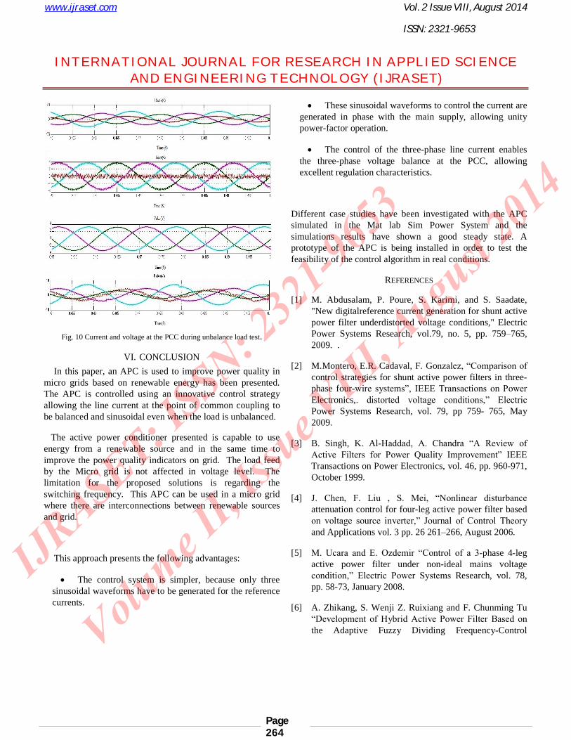
C. Unbalanced Load
When several single-phase loads are unequally distributed on a distribution system, the fluctuating power required from each of these loads can cause unbalanced voltage in a weak power system. Under unbalanced conditions, the distribution system will incur more losses and heating effects and will be less stable.
For this case study, the APC is used to compensate the unbalance induced by a resistive three-phase load. The phasea of the load is charged with 1050 W, the phase b with 1311 W and the phase c with 1749 W. The Fig. 10 shows the current and the voltage at the PCC. As shown in the previous section, the investigated APC is controlled such that the micro grid current required by the load (iabcn) is sinusoidal and balanced. Consequently, the voltage in this point is also balanced. To quantify the level of the voltage unbalance, the percentage of negative sequence unbalance is expressed in accordance with the definition of the ‘‘degree of unbalance in three-phase systems’’ [10]. As shown in Fig. 10, using the APC equipped with the proposed controller, the degree of the negative sequence unbalance is lower then 0.8%. It must be noticed that international standards admit unbalances lower than 2% [10].
www.ijraset.com Vol. 2 Issue VIII, August 2014
ISSN: 2321-9653
I N T E R N A T I O N A L J O U R N A L F O R R E S E A R C H I N A P P L I E D S C I E N C EAN D E N G I N E E R I N G T E C H N O L O G Y (I J R A S E T)
Page 264
Fig. 10 Current and voltage at the PCC during unbalance load test.
VI. CONCLUSION
In this paper, an APC is used to improve power quality in micro grids based on renewable energy has been presented. The APC is controlled using an innovative control strategy allowing the line current at the point of common coupling to be balanced and sinusoidal even when the load is unbalanced.
The active power conditioner presented is capable to use energy from a renewable source and in the same time to improve the power quality indicators on grid. The load feed by the Micro grid is not affected in voltage level. The limitation for the proposed solutions is regarding the switching frequency. This APC can be used in a micro grid where there are interconnections between renewable sources and grid.
This approach presents the following advantages:
The control system is simpler, because only three sinusoidal waveforms have to be generated for the reference currents.
These sinusoidal waveforms to control the current are generated in phase with the main supply, allowing unity power-factor operation.
The control of the three-phase line current enables the three-phase voltage balance at the PCC, allowing excellent regulation characteristics.
Different case studies have been investigated with the APC simulated in the Mat lab Sim Power System and the simulations results have shown a good steady state. A prototype of the APC is being installed in order to test the feasibility of the control algorithm in real conditions.
REFERENCES
[1] M. Abdusalam, P. Poure, S. Karimi, and S. Saadate, "New digitalreference current generation for shunt active power filter underdistorted voltage conditions," Electric Power Systems Research, vol.79, no. 5, pp. 759–765, 2009. .
[2] M.Montero, E.R. Cadaval, F. Gonzalez, “Comparison of control strategies for shunt active power filters in three-phase four-wire systems”, IEEE Transactions on Power Electronics,. distorted voltage conditions,” Electric Power Systems Research, vol. 79, pp 759- 765, May 2009.
[3] B. Singh, K. Al-Haddad, A. Chandra “A Review of Active Filters for Power Quality Improvement” IEEE Transactions on Power Electronics, vol. 46, pp. 960-971, October 1999.
[4] J. Chen, F. Liu , S. Mei, “Nonlinear disturbance attenuation control for four-leg active power filter based on voltage source inverter,” Journal of Control Theory and Applications vol. 3 pp. 26 261–266, August 2006.
[5] M. Ucara and E. Ozdemir “Control of a 3-phase 4-leg active power filter under non-ideal mains voltage condition,” Electric Power Systems Research, vol. 78, pp. 58-73, January 2008.
[6] A. Zhikang, S. Wenji Z. Ruixiang and F. Chunming Tu “Development of Hybrid Active Power Filter Based on the Adaptive Fuzzy Dividing Frequency-Control

www.ijraset.com Vol. 2 Issue VIII, August 2014
ISSN: 2321-9653
I N T E R N A T I O N A L J O U R N A L F O R R E S E A R C H I N A P P L I E D S C I E N C EAN D E N G I N E E R I N G T E C H N O L O G Y (I J R A S E T)
Page 265
Method,” IEEE Transactions on Power Delivery, vol. 24, pp. 424 – 432, January 2009.
[7] B.S. Chen and G. Joos, “Direct Power Control of Active Filters With Averaged Switching Frequency Regulation,” IEEE Transactions on Power Electronics, vol. 23, pp. 2729 - 2737, November 2008.
[8] M.P. Kazmierkowski, L. Malesani, “Current control techniques for three-phase voltage source PWM converters: a survey,” IEEE Transactions on Industrial Electronics vol. 45, pp. 691–703, October 1998.
[9] M. Nejad, S. Pierfederici, J.P. Martin, F. Meibody-Tabar, “Study of an hybrid current controller suitable for DC–DC or DC–AC applications,”IEEE Transactions on Power Electronics, vol. 22, pp. 2176–2186. November 2007.
[10] Copper Development Association, “Voltage Disturbances. Standard EN 50160 Voltage Characteristics in Public Distribution Systems,” 2004.
AUTHORS PROFILE
Putta Praveen Kumar Received the B.Tech degree in Electrical and Electronics Engineering from ArkayCollege of Engineering Technology,bodhan, India in 2011 and at present Pursuing M.Tech with the Specialization of Power Electronics and Electric Drives in Anurag Engineering College at
Kodad. His area of interest is Power Electronics, Electric Drives and Power systems.
Savarapu Chandra Sekhar Received his B.Tech Degree in Electrical & Electronics Engineering from RVR&JC college of Engineering, GUNTUR in 2001, M.Tech (High Voltage Engineering) degree in Electrical
and Electronics Engineering from Jawaharlal Nehru Technological University, Kakinada in 2004. He is pursuing Ph.D at K L University. Presently he is working as an associate professor and Head of the Department. His area of
interest includes Micro Grids, High voltage transmission and Power Systems.