Embed Size (px)
Citation preview

1
Geometric Modeling
Introduction“Geometric modeling is as important to CAD as governing equilibrium equations to classical engineering fields as mechanics and thermal fluids.”
intelligent decision on the types of entities necessary to use in a particular model to meet certain geometric requirements such as slopes and/or curvatures.interpretation of unexpected resultsevaluations of CAD/CAM systemsyinnovative use of the tools in particular applications.creation of new attributes, or modify the obtained models to benefit new engineering applications.understanding of terminology

2
The Role of Geometric Modeling in a CAD System
Computer
Mathematicalrepresentation(Database)
ComputerDisplay
UserInterface Drawing
Generation
Determine Determine
GeometricModelingTechnique
Analysis andManufacturing
General Requirements
• Complete part representation including topological and geometrical dataand geometrical data– Geometry: shape and dimensions– Topology: the connectivity and associativity of the
object entities; it determines the relational information between object entities
• Able to transfer data directly from CAD to CAE and CAM.
• Support various engineering applications, such as mass properties, mechanism analysis, FEA/FEM and tool path creation for CNC, and so on.

3
Topology and Geometry
Comments on Geometric Modeling
• Geometric modeling is only a means not the goal inGeometric modeling is only a means not the goal in engineering.
• Engineering analysis needs product geometry; the degree of detail depends on the analysis procedure that utilizes the geometry.
• There is no model that is sufficient to study all behavioral aspects of an engineering component or abehavioral aspects of an engineering component or a system.
• Attributes facilitate analysis and grow with applications

4
Basic Geometric Modeling Techniques• 2-D Projection (Drawings)• Wireframe Modelingg• Surface Modeling
Analytical SurfaceFree-form, Curved, & Sculptured Surface
• Solid ModelingConstructive Solid Geometry (CSG)Boundary Representation (B-Rep)…Feature Based Modeling Parametric Modeling
2-D Projection
Problems:
• Training is necessary to understand the drawing• Mistakes often occur
D t t b t li ti h• Does not support subsequent applications such as finite element analysis (FEA) or NC part programming

5
• Developed in 1960s and referred as “a stick figure” or “an edgerepresentation”
• The word “wireframe” is related to the fact that one may imagine
Wireframe Modeling
y ga wire that is bent to follow the object edges to generate a model.
• Model consists entirely of points, lines, arcs and circles, conics, and curves.
• In 3D wireframe model, an object is not recorded as a solid.Instead the vertices that define the boundary of the object, or theintersections of the edges of the object boundary are recordedas a collection of points and their connectivity.
front
fro nt
ambiguous
or
Example of Wireframe Modeling

6
Surface Modeling
• A surface model is a set of faces.
• A surface model consists of wireframe entities that form the basis to create surface entities.
• In general, a wireframe model can be extracted from a surface model by deleting or blanking all surface entities
• Shape design and representation of complex objects such as car, ship, and airplane bodies as well as castings
• Used to be separated, shape model are now incorporated into solid models (e.g. Pro/E)
Examples of Surface Models
Analytical SurfacesFree-form, Curved, orSculptured Surface

7
Examples of Surface Models• Surface models define only the geometry, no topology.• Shading is possibleShading is possible
Shading - by interpreting the polygons’• Direction (normal) • Spatial order
Solid Modeling• The solid modeling technique is based upon the "half-space"
concept. • The boundary of the model separates the interior and exterior of the y p
modeled object. • The object is defined by the volume space contained within the
defined boundary of the object. • In general speaking, a closed boundary is needed to define a solid
object.• informationally complete, valid, and unambiguous representation
(Spatial addressability)points in space to be classified relative to the object if it is– points in space to be classified relative to the object, if it is inside, outside, or on the object
• store both geometric and topological information; can verify whether two objects occupy the same space.
• improves the quality of design, improves visualization, and has potential for functional automation and integration.
8
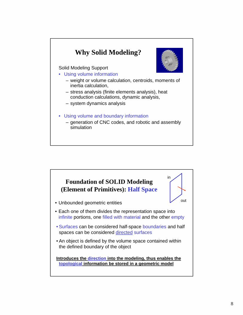
Why Solid Modeling?
Solid Modeling Support • Using volume information• Using volume information
– weight or volume calculation, centroids, moments of inertia calculation,
– stress analysis (finite elements analysis), heat conduction calculations, dynamic analysis,
– system dynamics analysis
• Using volume and boundary information– generation of CNC codes, and robotic and assembly
simulation
Foundation of SOLID Modeling (Element of Primitives): Half Space
• Unbounded geometric entities
in
outg
• Each one of them divides the representation space into infinite portions, one filled with material and the other empty
• Surfaces can be considered half-space boundaries and half spaces can be considered directed surfaces
• An object is defined by the volume space contained within• An object is defined by the volume space contained within the defined boundary of the object
Introduces the direction into the modeling, thus enables the topological information be stored in a geometric model

9
Half Spaces
• By specifying different boundary
in
outBy specifying different boundary surface, we can have any half-spaces;
• The most commonly used half-spaces are – planar, cylindrical, spherical, conical, and
toroidal.• By combining half-spaces (using Boolean• By combining half-spaces (using Boolean
operations) in a building block fashion, various solids can be constructed.
Half Spaces• Planar half-space• Cylindrical half-space
}0:),,{( <= zzyxH}:),,{( 222 RyxzyxH <+=
Block: {( , , ) : 0 , 0 , 0 }x y z x W y H and z D< < < < < <
Cylinder: }0,:),,{( 222 HzandRyxzyx <<<+

10
Example of Half Spaces
Different Solid Modeling Techniques
• Constructive Solid Geometry (CSG)• SweepingSweeping• Boundary Representation (B-Rep)• Feature-Based Modeling - uses feature-based primitives
to conduct a design
• Primitive Instancing - uses large numbers (200 - 300) of “primitives" to build object - used for programming NCprimitives to build object used for programming NC machine tools (past)
• Cell Decomposition, Spatial Enumeration, Octree(connected cubes of varying size) – used for irregular objects, image processing, medical applications (CT)

11
Information complete, unambiguous, accurate solid model
Constructive Solid Geometry (CSG)
• Pre-defined geometric primitives
• Boolean operations
• CSG tree structure (building process/approach)

12
Geometric Primitives - CSG• A collection of pre-defined (low level) geometric primitives• Sweeping of a 2D cross-section in the form of extrusion
and revolving are used to define the 3D shape (forand revolving are used to define the 3D shape (for uncommon shapes).
Low Level Geometric Primitives
DimensionsLocation
Orientation
Defined Geometric Features
Boolean Operationsin CSG
• Union, U• Intersection, n• Difference, or Subtraction, -
U n- -

13
CSG Tree
Alternative Paths of Modeling

14
A l thA lengthy, lousy process
SweepingSweeping can be carried out in two different forms:• Extrusion - to produce an object model from a 2D cross-section
shape, the direction of extrusion, and a given depth. Advanced applications include curved extrusion guideline and varyingapplications include curved extrusion guideline and varying cross-sections.
• Revolving - to produce a rotation part, either in solid or in shell shape. Revolving a 2D cross-section that is specified by a closed curve around the axis of symmetry forms the model of an axially symmetric object.
Sweeping is most convenient for lid ith t l ti lsolids with translational or
rotational symmetry. Sweeping also has the capability to guarantee a closed object.
Advanced: spatial sweeping; & varying cross-section

15
Boundary Representation (B-rep)• The boundary representation
method represents a solid as a collection of boundary surfaces.Th d t b d b th f thThe database records both of the surface geometry and the topological relations among these surfaces.
• Boundary representation does not guarantee that a group of boundary surfaces (often polygons) form a closed solid. The data are also not in the ideal form for modelin the ideal form for model calculations.
• This representation is used mainly for graphical displays.
• Many CAD systems have a hybriddata structure, using both CSG and B-rep at the same time (i.e. Pro/E).
• Object List ---- giving object name, a list of all its boundary surfaces, and the relation to other objects of the model.
Boundary Representation (B-rep)
, j• Surface List ---- giving surface name, a list of all its component
polygons, and the relation to other surfaces of the object.• Polygon List ---- giving polygon name, a list of all boundary
segments that form this polygon, and the relation to other polygons of the surface.
• Boundary List ---- giving boundary name, a list of all line segments that for this boundary, and the relation to other boundary lines of the polygon.
• Line List ---- giving line name, the name of its two end points, and the relation to other lines of the boundary line.
• Point List ---- giving point name, the X, Y and Z coordinates of the point and, and the relation to other end point of the line.

16
Euler Operators
MBFV: Make body, face, vertex
MME M k lti d
Body, Face, Polygon (Edge Loop), Edge, Vertex
MME: Make multi edges
MEF: Make edge, face
KEML: Kill edge, make loop
KFMLG: Kill face, make loop, genus
Feature-based, Parametric Models – Pro/E• Feature-based, Parametric Solid Modeling system represents the recent
advance of computer geometric modeling. It is used as the foundation of Pro/ENGINEER, etc.
• Feature-based, parametric solid modeling eliminated the direct use of common geometric primitives such as cone cylinder sphere etc sincecommon geometric primitives such as cone, cylinder, sphere, etc, since these primitives only represent low-level geometric entities. In designing and manufacturing mechanical parts, one would always refer to mechanical features.
• The modeling approach uses sweeping to form the main shape of the part, and build-in mechanical features to specify the detailed geometry of the model. These features include holes (through, blind, sink), rounds, chamfers, slots, etc. Operations to solid model, such as cut and shell(change a solid model into a hollow shell) are also supported. T t th 2D ti f i 2D k t h d t b• To create the 2D cross-section for sweeping, a 2D sketch needs to be generated in the 2D Sketcher. A user can sketch the rough shape of the closed shape. The system will automatically assign a dimension value of the sketched feature. The dimensions of the sketched feature can be changed at any time by simply entering the desired value, or kept as a variable, allowing even more convenient change of its value. The user has to provide all necessary dimensions to pass the section of cross-section generation. Problems of under- or over- dimensioning can be identified.

17
Pro/E Model GenerationIntroducing DatumPrimary Shape DefinitionPrimary Shape Definition• Drawing Rough 2D Cross-section in A 2D Sketcher • Defining the Precise Geometry• Building Solid Objects
– Extrusion to Form Depth– Revolving to Form Rotational Features– Sweeps and BlendsS eeps a d e ds
Adding Detailed Geometry• Making Holes and Cuts • Adding Rounds, Chamfers, Slots, and Shells
Summary - Geometric Modeling• Geometric Modeling is a fundamental CAD technique.• The capability of various CAD tools in geometric modeling is
usually used as a crucial factor in tool selection.• Wireframe models consist entirely of points lines and• Wireframe models consist entirely of points, lines, and
curves.Since wireframe models do not have “body knowledge”, topological data are not needed in construction.
• Surface models store topological information of their corresponding objects.Both surface models and solid models support shading.Surface models is still ambiguous and thus cannot support aSurface models is still ambiguous and thus cannot support a full range of engineering activities such as stress analysis.
• Solid models have complete, valid and unambiguous spatial addressability.In general, a wireframe model can be extracted from a surface or a solid model.

18
Wireframe Modeling• Advantages
Simple to constructDoes not require as much as computer time and memory as does surface or solid modeling (manufacturing display)does surface or solid modeling (manufacturing display)As a natural extension of drafting, it does not require extensive training of users.Form the basis for surface modeling as most surface algorithms require wireframe entities (such as points, lines and curves)
• DisadvantagesThe input time is substantial and increases rapidly with the complexity of the objectBoth topological and geometric data need to be user-input; while solid modeling requires only the input of geometric data.Unless the object is two-and-a-half dimensional, volume and mass properties, NC tool path generation, cross-sectioning, and interference cannot be calculated.
Surface Modeling• Advantages:
Less ambiguousProvide hidden line and surface algorithms to addgrealism to the displayed geometrySupport shadingSupport volume and mass calculation, finite element modeling, NC path generation, cross sectioning, and interference detection. (when complete)
• DisadvantagesRequire more training and mathematical background ofRequire more training and mathematical background of the usersRequire more CPU time and memoryStill ambiguous; no topological informationAwkward to construct

19
CSG and Brep1. CSG uses Euler operators in modeling.2. CSG needs low storage due to the simple tree structure and primitives.3. CSG primitives are constructed from the half-space concept.p p p4. Directed surfaces, Euler operations and Euler’s law fundamentally
distinguish the B-rep from wireframe modeling.5. Traditionally, CSG cannot model sculptured objects and thus is limited
in modeling capability. (This is no longer true for Adv. CAD systems, such as Pro/E)
6. It is easier to convert a CSG model to a wireframe model than to convert a B rep model to a wireframe modelconvert a B-rep model to a wireframe model.
7. Because both CSG and B-rep use face direction (half-space or surface normal), they can have a full “body knowledge.”
8. Generally speaking, most high-end CAD tools have the B-rep (or hybrid) method while most low-end tools rely heavily on the CSG method.
New Challenges to Geometric Modeling
M d li P M di• Modeling Porous Medium• Modeling Non-homogeneous
Materials– varying density– changing composition– multiple phases (solid, liquid)– …
• Biomedical Applications (geometry, materials, motion and mechanics)– Medical Images (surgical operation simulator, training and planning)– Computer models from CT scans (quantify motion in actual knees)


![Comparative Modeling.ppt [Read-Only]cbsu.tc.cornell.edu/Workshop/2002_cd/lectures/Comparative_Modeling.pdfinteractions of a protein with other molecules are ... •Protein-protein](https://img.dokumen.tips/doc/110x75/5f4faad1f5f0f738b7283867/comparative-read-onlycbsutccornelleduworkshop2002cdlecturescomparativemodelingpdf.jpg)