Embed Size (px)
Citation preview

Group 5 – James Pacey, Ray Brown, Brent Sutherland

¡ Definition: To model a constant velocity birfield axle joint and
shaft, and perform a stress analysis on the birfield ¡ Objectives:
▪ Gain further CAD experience with Solidworks and ANSYS, try more advanced techniques and focus on organization
▪ Analyze stress on the birfield using Solidworks simulator and ANSYS ▪ Try motion analysis and model rendering

Application: • Used in front axle of four wheel drive vehicles • Transmit torque from differential to wheel while allowing the wheels to steer • Weak link with larger tires and low gearing

¡ Exploded view of the axle assembly
Birfield outer bell
Bearing Cage
(6) Ball bearings
Inner bearing race
Inner snap ring
Outer snap ring
Inner shaft


¡ Model ¼ or ½ of a circular part and use mirror to produce complete part
¡ Cut loft feature used to create splines
¡ Sweep cut along a spine to create bearing races
¡ Mating parts using sketch geometry
¡ FEA using ANSYS

• Symmetry and mirror features were used to reduce file size and simplify part tree

¡ Used two 3D sketch planes ¡ Cut loft between two planes to create a spline ¡ Circular pattern for rest of the splines

¡ Sweep cut feature used for both inner and outer bearing races ¡ Circular pattern used to cut the rest

¡ Measuring certain features on the actual parts to input into Solidworks ▪ Splines ▪ Elliptical bearing tracks
¡ Mating the ball bearings in the birfield assembly ▪ Difficult to constrain the bearings to stay in the races

¡ Exported model geometry data using .IGES ¡ Element type: 3-‐D 10-‐Node Tetrahedral Structural Solid (Solid 187)
§ Well suited for complex shapes § High order element (quadratic)
¡ Volume meshed using auto mesh. ¡ Birfield shortened to exclude most of the shaft to help increase mesh
density in bell.

Location Von Mises Stress
Ball Contact Point 2 GPa
Shaft Fillet 830 Mpa
Ball Track Center 515 Mpa
-‐Fixed the back face of the shaft -‐Applied forces at the contact points of the ball bearings.

¡ Loading applied to nodes closest to application points. § Slight asymmetrical loading § High contract stress due to point loads § Due to concave application surface cluster points were difficult to apply. § Loads closest to the application points were not always on the surface.
¡ Relatively coarse mesh § Limited by student version § Poorer resolution than desired
¡ Attempted multi-‐body solution § Long running times § System memory limitations encountered § No-‐linear solutions often crashed the program

Solidworks FEA results Loca%on Stress
Thin sec)on of outer bearing race 500 MPa Sha7 Fillet 750 MPa Ball Bearing Contact Point 1.8 GPa

Location ANSYS Solid Works % Difference
Ball Contact Point 2 GPa 1.8 GPa 10 %
Shaft Fillet 830 MPa 750 MPa 9.6%
Ball Track Center 515 MPa 500 MPa 2.9%
Program Advantages Disadvantages
Simulation Express -‐Simple to implement -‐Allows integrated design
-‐Limited options for problem setup -‐Less advanced output options
ASYS Academic 12.0 Teaching Introductory
-‐Allows more advanced analysis -‐Extremely customizable
-‐Limited by intro version -‐Limited geometric manipulation -‐Steep learning curve

¡ Model rendered using Solidworks Photoworks


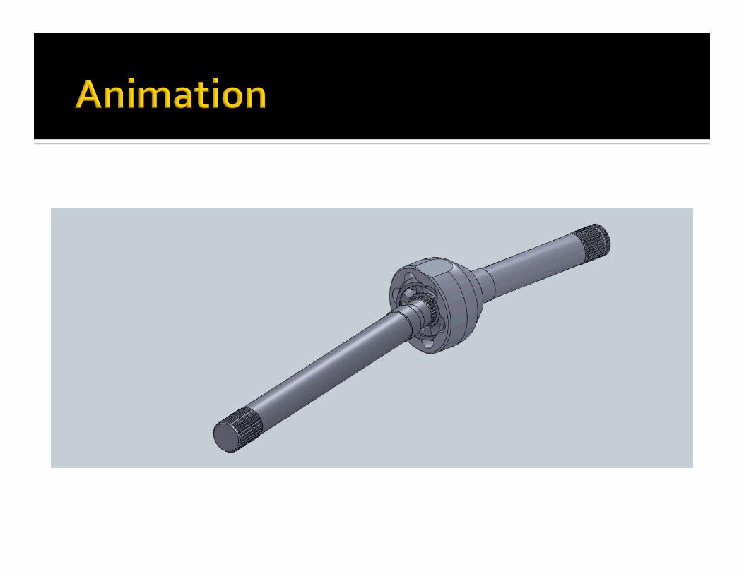

¡ Gained more experience with Solidworks § Using more complex features and techniques § First time using Photoview rendering and model animation
¡ Gave us a chance to try ANSYS FEA

¡ ?


![Approximate Lie Group Analysis of Finite–difference Equations · Approximate Lie Group Analysis of Finite–difference Equations A.M.Latypov ... Levi and Winternitz [8] applied](https://img.dokumen.tips/doc/110x75/5edcb4acad6a402d66677c2b/approximate-lie-group-analysis-of-finiteadiierence-equations-approximate-lie.jpg)