Embed Size (px)
DESCRIPTION
DEVELOPMENT IN 2010 Fajar Nur Hidayat, M.Ed. By TABLE OF CONTENTS DRAWING IN FLASH 9 1 Development Environment Of Macromedia Flash ...................................... 1
Citation preview

INTRODUCTION TO COMPUTER
MULTIMEDIA AND ITS
DEVELOPMENT IN
MATHEMATICS TEACHING AND
LEARNING
By
Fajar Nur Hidayat, M.Ed.
2010


TABLE OF CONTENTS
FOREWORD i
TABLE OF CONTENTS iii
INTRODUCTION TO MACROMEDIA FLASH 8 1
Development Environment Of Macromedia Flash ...................................... 1
DRAWING IN FLASH 9
Selection Tool (V) ...................................................................................... 10
Subselection Tool (A) ................................................................................ 11
Free Transform Tool (Q) ........................................................................... 11
Gradient Transform Tool (F) ...................................................................... 13
Line Tool(N) .............................................................................................. 14
Lasso Tool (L) ............................................................................................ 15
Pen Tool (P) ............................................................................................... 16
Text Tool(T) ............................................................................................... 17
Oval Tool(O) .............................................................................................. 18
Rectangle Tool(R) ...................................................................................... 19
Polystar Tool .............................................................................................. 19
Pencil Tool(Y) ............................................................................................ 20
Brush Tool(Y) ............................................................................................ 20
Inkl Battle Tool(S) ..................................................................................... 21
Paint Bucket Tool(K) ................................................................................. 22
Dropper Tool(K) ........................................................................................ 23
EraserTool(E) ............................................................................................. 23

TABLE OF CONTENTS
Using Grid and Ruler ................................................................................. 23
ANIMATION IN FLASH 25
Shape Tween ........................................................................................... 27
Frame by Frame Animation ................................................................ 30
Motion Guide Animation .................................................................... 32
Masking Animation .............................................................................. 34
Animation Using Timeline Effect ..................................................... 36
SYMBOLS AND INTERACTIVITY 39
Creating Button ...................................................................................... 40
Giving Command to a Button ............................................................ 42

1
INTRODUCTION TO MACROMEDIA
FLASH 8
Macromedia Flash is a tool to make various ranges of animation,
presentation, game, and even teaching and learning media. Besides, it can
also be used as a tool to design web and other multimedia applications.
DEVELOPMENT ENVIRONMENT OF MACROMEDIA FLASH.
Once you open Macromedia Flash program, you will see the front page
as shown below.
In this front page, we can see some menus such as:
Open a Recent Item: a category to show all flash files/documents made
using file extension .fla
Open: a command to open documents already made, yet they are not
available in Open Recent Item due to the space limit.
Create New: a command to make a new flash document/file.
Create from Template: a template provided by Macromedia in the form

INTRODUCTION TO MACROMEDIA FLASH 8
2
of user interface.
Extend: thi s command wil l cal l Macromedia websi te for
Exchange session .
If you choose Create New > Flash Document, you will see the display
of new file or document from the working area of Macromedia Flash as
shown in the figure below, alongside the important parts in the
development environment of Macromedia Flash.
Some of important parts in the development environment are: Menu,
Toolbox, Timeline, Stage and Panel.
Menu
Menu in Macromedia Flash consists of: File, Edit, View, Insert,
Modify, Text Commands, Control, Window and Help. You can
also view the submenu under each menu by clicking once on the
menu that you choose. As an example, if we click Insert menu, we
will see the display like one below.

3
Stage
Stage is also called layer. Stage is used to play objects that will be
animated. We can create picture, text, give color and many other
things to do in Stage.
Toolbox:
Tools are used to draw and manipulate a picture/an object. Tools are
divided into four primary parts, those are:
o Tools, in this part it is used to edit and manipulate objects.
The icons available in this part will be discussed individually
in Drawing Using Flash part.
o View is used to zoom in or out the display screen in Stage.
o Colors which in this part there is a palette to change the color
of line and filling.
o Option is modifiers from every chosen tool. Each tool has
different modifiers.
Timeline
Timeline is a component that is used to manage and control the way
the animation works. Timeline consists of a few layers which are used
to place one or some objects in stage in order to be able to manage
with other objects. Each layer is made of frames used to set the speed

INTRODUCTION TO MACROMEDIA FLASH 8
4
of the animation. The longer the frame in the layer, the longer the
animation will be played. The picture below shows the important
parts of a timeline.
Panel
Some of the important panels in Macromedia Flash are: Properties &
Filters & Parameters, Actions, Library, Color and Align & Info
& Transform.
o Properties & Filters & Parameters Panel
This panel is situated under stage. You can press Ctrl+F3 to show
it up or hide it. Properties & Filters & Parameters panel is used
to set the size of background, background color, the speed of
animation and so on. The picture below shows properties panel.

5
o Actions Panel
Actions panel is used to write Flash script or programming
languages (ActionScript). You can just type it directly on the
Actions screen or use the assistance provided by Macromedia
Flash. You can press F9 to show the panel up or to hide it.
o Library Panel
Library is a panel to save objects such as graphics or pictures,
buttons, movies, or sounds either produced directly in the stage or
imported from other source outside stage. Use shortcut Ctrl+L to
view or to hide this panel.

INTRODUCTION TO MACROMEDIA FLASH 8
6
o Color Panel
Color panel is a panel to choose color that will be used in
producing objects in stage. There are two subpanels in this panel,
namely Color Mixer and Swatches. Shortcut used for Color Mixer
is Shift+F9, and shortcut for Color Swatches is Ctrl+F9.
o Align & Info & Transform Panel
To show this panel up, you can press Ctrl+K on the keyboard.
This panel is used to arrange the position of objects, whether it
would be put in the center of the stage, left side, right side or other
side required. This panel also allows you to rotate objects using
Transform.

7
Status Bar
The picture on the left is the menu status bar used
for altering zooming/overall stage size. Fit in
Window option will only display stage, Show
Frame option will display Stage and Work Area,
and Show All will focus on the existing object.
To change background color and size of the stage, you can do either
these steps:
o Right-click on the stage, then choose Document Properties and a
dialog box like the one below will appear.
o Or, you can choose from Menu>Modify>Document (Ctrl+J).

INTRODUCTION TO MACROMEDIA FLASH 8
8
You can alter the size of the stage in Dimensions option in which the
minimum width and height of the stage is 1 pixel, and the maximum
is 2880 pixels.
In Match option, there are:
o Printer. To change stage to the maximum available print area
(the size of the stage will adapt with the size of paper used).
o Contents. To adjust width and height of the stage with the
available object. If the object is on the top left of the Stage, the
width of the Stage is the same as the width of the object. If not,
the distance from left and top of the stage to the object will be the
same as the distance from right of and below the stage.
o Default. To change the size of the stage back to standard i.e. 550
x 400 pixels.
To change the background color of the stage, click background
color box and you can choose the color you want from color dialog
box.
Frame rate option is used to adjust the speed of the animation. The
standard speed is 12 frames per second. To make it quicker, you can
fill in bigger value.

9
DRAWING IN FLASH
Flash has an ability to draw various objects using provided tool panel
facility. The location of tool panel default is on the right side of
Macromedia Flash screen. Tool panel consists of a set of tools used to
draw and edit graphics and
texts which is divided into
four parts, those are:
Tools, View, Colors and
Options (see figure 1).
Tools contains apparatus
to draw lines and shapes,
to color, to write text and
to choose object to modify.
View contains hand tool
used to slide the display on
stage, and zoom tool which
is to zoom in and zoom out
the display on stage.
Colors contains tools and
icon used to change stroke (the outlines of an object) and fill (the area
inside an object) colors. Options contains alternative tools that can be
used. For instance, brush tool has various sizes to use. Next, we will
discuss the use of each tool.
Tools
View tool
Color tools
Option
Figure 1. Tools panel
Selection

DRAWING IN FLASH
10
1. Selection Tool (V)
This is used to pick and move object, either in the form of shape,
line, dot, or symbol. Besides, it can also be functioned to draw. There
are four modes of selection tool, namely: move corner, bend curve,
move object and no
object. Every time we
activate selection tool,
the cursor will change
as its active mode as
in figure 2.
Move corner will be
active whenever the cursor is put on the corner of an object and used
to move/slide the corner of the object. Bend curve will be active if
the cursor is pointed to the side/line of an object and used to modify
the curve/line of the object. Move object will be active as the cursor
is upon an object and used to move it. No object is a mode when the
selection tool is not in the position of being near an object.
Using these variations of selection tool, we can create the various
shapes as shown in figure 3. The group of objects on the left uses
move corner, the one in the middle uses bend curve, and the one on
the right uses general selection mode.
Figure 2. Selection tool modes
Figure 3. Variations of selection tool use

11
Figure 4. Edit a circle using subselection
tool
2. Subselection Tool (A)
Subselection tool
functions to modify an
object in the form of
stroke/line. An object
picked using
subselection tool will
show anchor point which enables us to edit that object. Subselection
tool is similar to selection tool with move corner mode, however, it is
equipped with bezier and an ability to erase dots. For an instance,
figure 4 shows a circle chosen with subselection tool. We can see
dots upon the line of the circle. The object on the right is the circle
after haviing edited using bezier as we can see the line of bezier.
3. Free Transform Tool (Q)
This tool is used to transform an object by changing its size or to
rotate or to skew the object as what we expect. To make it work, we
need to activate free transform tool, then choose an object that we
want to transform. An active object will be marked with a box having
eight black square dots upon its outline which is used to transform
and one dot as the center of the object‟s pivot point. Besides, the
object can be moved using this facility if the cursor is changed into
move object mode. There are four options provided by free transform
tool: Rotate and Skew, Scale, Distort, and Envelope.

DRAWING IN FLASH
12
Change the size of the object
To enlarge or reduce the size of an object, we
can use option scale from free transform
tool. Point the cursor to one of the eight
black square dots of the active object until
the cursor shaped a line with two arrows on
its both ends as shown in figure 5. To change the size of an object
without changing the proportion, we can slide it from the corner
point. If we do it from the dots in the middle, the shape of the
object will turn into taller, shorter, wider, or slimmer.
Rotate and skew an object
To rotate or skew an object, we can use the option rotate and
skew. First, activate the object. Then, to rotate the object, point
the cursor around the dots in the outside corner until we can see
three-quarter-circle-shaped arrows as in figure 6. Hold the mouse
and move the object to the direction we want. We can also
change the pivot point of the object by sliding the white circle in
the center of the
object to the location
we want.
To skew an object,
you can point the cursor to the outline of
the object until you can see the “equal”
mark with arrows in its corners as shown in figure 7. Hold the
mouse and slide it to the direction you want.
Figure 5
Figure 6
Figure 7

13
Change the shape of an object
To change the shape of an object using free transform tool, we
have to activate the option distort or envelope first. Distort is
used to change the shape of an object by moving the points of
each corner. Figure 8 shows the shape of an object before and
after it is changed using distort. From the original shape on the
left, we move one top-right corner point up and we will get the
new shape as one on the right side of figure 8. Envelope is almost
the same as subselection tool. It will show bezier line to change
the shape of an object through the change of its strokes. Figure 9
shows the transformation using bezier line (symbolized as black
dots). We can see the left corner part of an object on the left side
is modified becomes the one on the right side.
4. Gradient Transform Tool (F)
It is used to transform the color gradation of fill by setting the size,
direction, or center of the fill. This tool functions when the object has
fill with color gradation. There are two kinds of color gradation of
fill, namely linear gradient and radial gradient. Linear gradient is a
color gradation in which the gradation follows a linear pattern of
Figure 8. Distort Figure 9. Envelope

DRAWING IN FLASH
14
horizontal line, while radial gradient is a gradation in which the color
gradation forms a circle-shaped pattern. We can choose either of
these two patterns from color mixer located in the right panel or
dialog box of fill color where the gradation option is down under.
Figure 10 shows color mixer in the form of linear gradient and figure
11 shows gradient transform tool for linear gradient. By sliding the
dots in the circle, we will obtain the color gradation we want. The dot
in the middle of the circle is the center point of a gradation. Figure 12
shows the fill transformation in linear gradient.
5. Line Tool (N)
Line tool is used to create a line. To activate it, we just click the Line
tool. To create a line, click a location on stage, then hold the mouse
and move the cursor on the stage. When we drag the cursor, a line
will show up from the point we click the mouse. The line we are
making is not realized yet until we release the mouse. You can draw
horizontal line, vertical line or diagonal line with 45o
angle by
pressing SHIFT key at the same time as you draw the line.
Figure 10. Color Mixer Figure 11. Radial gradient Figure 12. Linear gradient
15
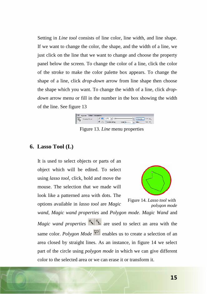
Setting in Line tool consists of line color, line width, and line shape.
If we want to change the color, the shape, and the width of a line, we
just click on the line that we want to change and choose the property
panel below the screen. To change the color of a line, click the color
of the stroke to make the color palette box appears. To change the
shape of a line, click drop-down arrow from line shape then choose
the shape which you want. To change the width of a line, click drop-
down arrow menu or fill in the number in the box showing the width
of the line. See figure 13
6. Lasso Tool (L)
It is used to select objects or parts of an
object which will be edited. To select
using lasso tool, click, hold and move the
mouse. The selection that we made will
look like a patterned area with dots. The
options available in lasso tool are Magic
wand, Magic wand properties and Polygon mode. Magic Wand and
Magic wand properties are used to select an area with the
same color. Polygon Mode enables us to create a selection of an
area closed by straight lines. As an instance, in figure 14 we select
part of the circle using polygon mode in which we can give different
color to the selected area or we can erase it or transform it.
Figure 13. Line menu properties
Figure 14. Lasso tool with
polygon mode

DRAWING IN FLASH
16
7. Pen Tool (P)
Pen tool is used to draw line or curve by creating the order of dots
that are connected automatically which is called anchor point. We can
create straight line or curve line segment and adjust the angles and the
length of the straight line segment and the elevation of the curve line
segment.
There are two methods in drawing using Pen tool:
1. By clicking to create dots on straight line segment.
2. By clicking and dragging to create dots on curve line segment.
How to make a straight line using Pen Tool:
1. Click on Pen Tool.
2. Click once on stage to create initial anchor point.
3. Next, make second anchor point by clicking
the mouse once on stage while pressing Shift
button on keyboard at the same time. Pressing
Shift button is intended to make a line segment which is created
between two anchor points. It forms a straight line or a line with
45o elevation and its multiples (look figure 15).
4. A straight line has been created. Once you finish drawing an
object using Pen Tool, click on tools beside Pen Tool or quickly
click twice to see the form of the object created.
How to make a curve line:
1. Click Pen Tool.
Figure 15

17
1 2 3
Figure 16. Create a curve line using pen
tool
2. Click once on stage, hold the mouse and drag it to the direction of
the curvature. Once the mouse is dragged on stage, the tangent
handles will appear as the reference direction of the curve (figure
16.1)
3. Release the mouse.
4. Position the cursor on the place we want for the second anchor
point. Click the
mouse once and
hold it, then drag to
the position which
you want to direct
the curve (Figure
16.2).
5. Release the mouse. You can click tools instead of Pen Tool to see
the object created. The curve made will look like one in figure
16.3.
8. Text Tool (T)
Text tool is used to enter and edit
text. There are two ways to enter
text. The first way is by clicking text
tool option on toolbar, then we click
the mouse on stage until we can see a text box with little circle on its
top right appears as in figure 17. The text box is a place where we
insert text. The text box will adjust its size as we insert the text.
Figure 17

DRAWING IN FLASH
18
The second way is by sliding the mouse to
adjust the length of the text box which is
called paragraph box. The box will then
appear with particular permanent length,
so when we insert the longer text than its length, the rest of the text
will be moved to the next line.
We can modify the text
attributes such as type,
size, font color, bold,
italic, or alignment by
setting it in property panel as in figure 19.
There are two ways to edit text. First, click one of the letters using
selection tool to make the text box appear. In active position, we can
modify all text in the text box. The second way is by clicking one of
the letters using text tool to make the text box appear. Then, we
highlight the text we want to modify. This way will only modify the
text that we highlight.
9. Oval Tool (O)
Oval tool is used to create circular forms. Click Oval tool on toolbar
to activate it. To make circular form, you can click, hold and drag the
mouse. The circular form will be created as the mouse moves and
you can see it as it appears after you release the mouse. To make a
circle form, you can press SHIFT as you drag the mouse. The way to
set attributes in Oval tool is similar to one in line tool as shown in
Figure 18
Figure 19. Text property

19
figure 13, those are line color, line width, line form, and filling,
however, in oval tool we can set the fill color.
10. Rectangle Tool (R)
Rectangle tool is used to make
rectangle form. Click rectangle
tool on toolbar to activate it.
Then, click, hold and drag the
mouse, the rectangle form will
appear following the pointer direction of the mouse and you can see
it as you release the mouse. To make a square, press SHIFT when
you draw. The setting of this tool is similar to one in the oval tool.
One additional setting in this tool is round rectangle radius that you
can find in toolbar options. Rectangular radius is used to change the
rectangular corner which is from angular form into round form. To
make it appear, you can just press Round Rectangle Radius icon
until you can see Rectangle Setting dialog box. Then, insert the value
of the radius of the rectangle corner. The rectangle that we make will
have round-form corner as in figure 20, with its radius = 20.
11. Polystar Tool
Polystar tool is a subtool of rectangle tool. If we click rectangle tool
button in toolbox and hold it for about 1-2 seconds, we can see option
box of Rectangle Tool and Polystar Tool. Choose Polystar tool to
create a poly-angle (x-sided) star or polygonal figure. We can set the
shape of the figure either in the form of star or polygon and the
Figure 20. Rectangle with
round radius = 20

DRAWING IN FLASH
20
number of its sides by opening properties panel (Ctrl+F3) and choose
option. Next step is we can then draw the figure on stage.
12. Pencil Tool (Y)
Pencil Tool is used to draw line or any shape we want. There are
three available options namely Straighten (to draw straight line),
Smooth (to draw smooth curve line) and Ink (to freely draw any
shape without modification).
To create a line, click, hold and drag the mouse until we can see a
line formed. The setting for color, width, and type in pencil tool is
similar to one in line tool in property panel. Straighten mode is used
to help straighten the line we
create, however, the result
will not be as straight as if
we make line using Line
Tool. Smooth mode is used
to help smooth the line that
we make. Ink mode is used
to erase Flash assistance in smoothing the line. Using ink mode will
give the result as we make a line by our own without flash
assistance. To get a clearer view, you can see figure 21.
13. Brush Tool (Y)
Brush Tool is used to fill color. You can activate Brush Tool by
clicking the icon, then click and drag the mouse to the space we want
Ink/original Straighten Smooth
Figure 21. Three types of Pencil
tool mode

21
to draw, and we will get a scratch.
To finish, just release the mouse.
The options available in Brush Tool
are: Brush Mode, fill color, Brush
Size, Brush Shape, and Lock Fill
(figure 22).
Brush Mode is used to define the type of the brush scratch as we
draw using Brush Tool. Brush mode sets the relations between the
brush and other objects. So, in order to make distinction, you had
better make an object first before you make an experiment with the
brush mode. There are five selections of painting, those are: Paint
Normal, Paint Fill, Paint Behind, Paint Selection and Paint Inside.
Paint Normal is used to cover all the object field including the border
line, the filling field, or both. Paint Fill is to cover the object field
regardless border line. Besides, by using Paint Fill we can draw on
other objects instead of those two shapes. Paint Behind is used to fill
behind the object without covering the object. Paint Selection is used
to fill the selected area. Paint Inside is to fill inside an object only
and leave the outer part untouched. Brush Size is used to set the size
of the brush. Brush Shape is to select the brush shape. Lock Fill is
utilized to lock (not to use) gradient fill in Brush Tool.
14. Ink Bottle Tool (S)
Ink Bottle Tool is used to modify a border line or to add a border line
to an object, for example in oval shape. To set the attributes of a line
Figure 22. Brush Tool options
DRAWING IN FLASH
22
such as color, width, and line shape, we can do it from property panel
in stroke panel, then click on the line we want to modify.
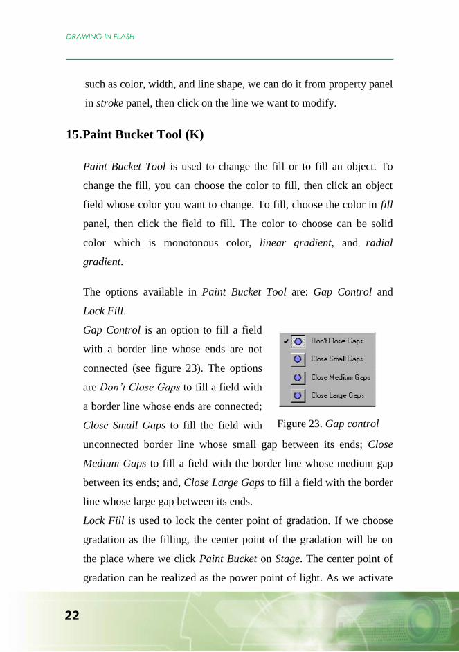
15. Paint Bucket Tool (K)
Paint Bucket Tool is used to change the fill or to fill an object. To
change the fill, you can choose the color to fill, then click an object
field whose color you want to change. To fill, choose the color in fill
panel, then click the field to fill. The color to choose can be solid
color which is monotonous color, linear gradient, and radial
gradient.
The options available in Paint Bucket Tool are: Gap Control and
Lock Fill.
Gap Control is an option to fill a field
with a border line whose ends are not
connected (see figure 23). The options
are Don’t Close Gaps to fill a field with
a border line whose ends are connected;
Close Small Gaps to fill the field with
unconnected border line whose small gap between its ends; Close
Medium Gaps to fill a field with the border line whose medium gap
between its ends; and, Close Large Gaps to fill a field with the border
line whose large gap between its ends.
Lock Fill is used to lock the center point of gradation. If we choose
gradation as the filling, the center point of the gradation will be on
the place where we click Paint Bucket on Stage. The center point of
gradation can be realized as the power point of light. As we activate
Figure 23. Gap control

23
Lock Fill by clicking the icon, we can still fill the color using
gradation but we cannot change the existing center point of gradation.
It will not change its position though we click Paint Bucket on other
spot on Stage.
16. Dropper Tool (I)
Dropper Tool is used to take color sample from an existing object so
that we can use it to color other object to be similar to the existing
one.
17. Eraser Tool (E)
Eraser Tool is used to erase part of drawing on Stage. The options
available in Eraser Tool are: Erase Mode, Faucet and Brush Size.
Erase Mode is used to define the way to erase from Eraser Tool. The
function of each mode is about the same as the one in fill tool. Faucet
is used to erase all fill completely or border line with only one click.
Erase Shape is used to define the eraser shape we use.
18. Using Grid and ruler
Grid is a group of intersecting lines horizontally and vertically with
particular distance as a guide to draw and to put the elements. It has
the same function as graphic paper in non-digital world. Flash also
uses grid to straighten the object if we activate Snap to Grid feature.
Because grid is only a helping tool, it does not appear in our movie
result. The way to make it appear is from menu View, then, we

DRAWING IN FLASH
24
choose Grid >
Show Grid. If
this feature is
active, there
will be check
mark beside it
and on stage
showing grid as a part of Stage. Grid on stage can be set as we want
for its color, width and length. We just use menu view>grid>edit
grid to show dialog box to set the color and size of the grid.
Ruler and guides help us to draw an object with precise size, shape,
and position on Stage. To view ruler, choose menu view>rulers.
Guides is to line up objects on stage with ruler. To use it, you can
click rulers on the sides of the screen, you can choose either the
horizontal one or the vertical one. Hold and drag the mouse to the
stage and position it to the space you want. To set the color and the
size of guides, choose menu file>guides>edit guides.
Exercise
Try to draw the objects and do the mathematics equations as shown
below using Flash.
Ruler
Guide
s
Grid
Figure 24. Ruler, guides,
and grid

25
ANIMATION IN FLASH
Macromedia Flash is known as software used to make animation,
especially for web application. Flash has some techniques in making
animation such as motion tweening, shape tweening, frame by frame
animation, motion guide, masking, and text animation.
MOTION TWEEN
Motion tween (motion animation) is used to move an object from one
location (starting frame) to another location (ending frame) on stage.
Motion tween can only be used by one object – which includes symbol,
group object or in combined texts – on one layer. So, if you want to move
many objects, you must use many layers.
You can follow these steps:
1. Open macromedia flash and choose Create New Flash Document
2. Import file from Clip art Microsoft Office using this way:
a. Choose File >
Import > Import to
Library, but first you
have to transform the
file type into WMF
and find file
“C:\Program
Files\Microsoft

ANIMATION IN FLASH
26
Office\MEDIA\CAGCAT10\J0183328.WMF” which
contains a picture of a bus. Click Open.
b. In library you will see a bus with its background, next, drag
the picture to the stage as shown in the figure beside this.
c. Since we just want to get the picture of the bus, we have to
erase the background. We can edit the graphic by clicking
twice on the picture of the bus and erase the picture that we
want to get rid of by pointing at it and press DEL button on
keyboard. Then, we will only get the picture of the bus. To get
out of the edit position of the picture click scene 1 in timeline.
3. Set the position of the bus and its size on stage which then will be
the starting point of the animation we make.
4. Create keyframe in frame 30 on layer 1 by right-clicking frame 30
and choose Insert Keyframe from the menu.
5. Still in frame 30, slide the picture of the bus to the right as you
want which then will be the ending point of the animation we
make.
6. Right click Frame 1 and choose Create Motion Tween, and you
can see an arrow on Timeline as in the figure below.
7. Play the animation by pressing CTRL + ENTER buttons on
keyboard.
8. Save the file you just created.

27
Task:
Create an additional animation to make the bus go back and forth.
SHAPE TWEEN
Shape tween is used to create animation which involves shape
transformation. Different from motion tween, shape tween cannot be
done with group object or a symbol. So, we have to break them apart
first or ungroup them.
Let‟s create an animation of the transformation from a rectangular to a
parallelogram.
1. Make a new document in macromedia flash, choose File > New
or by pressing CTRL+N button then choose Flash Document
2. Draw a rectangular using rectangle tool.
3. Click frame 1. In property panel, you
will see the box shown on the right
side of the tween that you can choose
by clicking the arrow containing the types of available tween and
choose shape (see the picture beside this).

ANIMATION IN FLASH
28
4. Click frame 30, then press F6 to add keyframe in that frame.
5. Remember, still in frame 30, drag the picture of rectangular to
other location on stage and change the rectangular into a
parallelogram. The result will be as one shown in the figure
below. Next, see the result by clicking test movie icon or pressing
CTRL + ENTER.
6. You will see that the rectangular transforms into a parallelogram.
However, the transformation does not go as we expect to. To
direct the shape transformation as we expect, Macromedia Flash
provides shape hints feature to define the points put in the object
in the starting and ending frames.
To add shape hint on shape tween
7. Click frame 1, choose Modify > Shape > Add Shape Hint in bar
menu or press CTRL+SHIFT+H, and you will see a red circle
with a letter inside in the object as shown in the figure below.
Move the red circle to the location in the object as you want, for
instance, you put it in the corner point of the rectangular. Add as
many shape hint points as you want and put them in the position.

29
8. Click frame 30 (ending frame), move the shape hint points to the
ending shape of the object as in the picture below. Then, you can
see the result by pressing CTRL+ENTER. If the animation still
does not go as you wish, you can put more shape hint points.
9. Save your work.
Task:
Complete the animation by adding other square shape transformations
such as transformation to trapezium, rhombus, and diamond (kite).

ANIMATION IN FLASH
30
FRAME BY FRAME ANIMATION
Frame by frame animation is an animation designed by changing the
appearance frame by frame. This type of animation is the most flexible
one, yet takes a lot of creativity and a quite long time to design.
The example below shows the odd number pattern.
1. Create a new document in macromedia flash, choose File
> New or press CTRL+N buttons and choose Flash
Document
2. Draw a circle and write number 1 below it as shown in the
figure beside this.
3. Click frame 10, and press F6 to add keyframe in that frame. Then,
add three more circles and number 3 on their right side. Use oval tool
to draw and Text tool to write number.
4. Click frame 20, and press F6 to add keyframe in the frame. Then, add
five more circles and number 5 on their right side as in point 3.
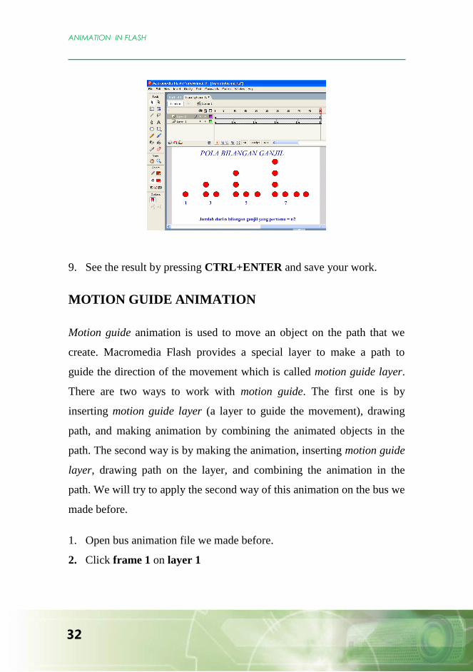
5. Click frame 30, and press F6 to add keyframe in the frame. Then, add
seven more circles and number 7 on their right side, so we can get the
figure as shown below.
1

31
6. Click frame 40, and press F6 to add keyframe in the frame. Then
write ”The number of n first odd integers = n2”
. To make square
symbol, you can highlight number 2 and choose superscript in combo
normal box in property.
7. Click frame 50 and press F5 (or right click on frame 50 and choose
insert frame) to lengthen frame 40.
8. Make new layer by choosing menu Insert > Timeline > Layer or
you can use insert layer icon at bottom left of the layer as shown in
the figure above. Then, click frame 1 in layer 2 and choose Text
Tool. Next, type ”Odd Integers Pattern”. Use bigger font for the
phrase and make it as a title, so you will see the screen as shown
below.
Insert layer
ANIMATION IN FLASH
32
9. See the result by pressing CTRL+ENTER and save your work.
MOTION GUIDE ANIMATION
Motion guide animation is used to move an object on the path that we
create. Macromedia Flash provides a special layer to make a path to
guide the direction of the movement which is called motion guide layer.
There are two ways to work with motion guide. The first one is by
inserting motion guide layer (a layer to guide the movement), drawing
path, and making animation by combining the animated objects in the
path. The second way is by making the animation, inserting motion guide
layer, drawing path on the layer, and combining the animation in the
path. We will try to apply the second way of this animation on the bus we
made before.
1. Open bus animation file we made before.
2. Click frame 1 on layer 1

33
3. Click the menu bar, choose Insert > Timeline >
Motion Guide. Layer 1 will be under Layer
Guide: layer 1 with the position a bit sticks out.
4. Click frame 1 on layer guide, click Pencil tool icon on Tool
panel, click Smoth option icon in the option in Tool panel. Start
making a path by drawing a line on stage
5. Click selection tool icon on tool panel.
Click frame 1 in layer 1. If the centre
point of the transformation of the bus is
not attached on the starting point, slide the
bus until the center point of the transformation is attached on the path
as shown in the figure.
6. Like point 5, the centre point of the transformation in frame 30 of
layer 1 should also be attached to the end of the path.
7. Run the animation by pressing CTRL+ENTER. And, you can see
that the bus will move with permanent position.
8. To change the position of the bus to match the direction of the path,
click frame 1 on layer 1.
9. As you are sure that the bus picture is accepted, tick the box in
Orient to path in property panel.
10. Play the animation and see the difference.
Task:
Make an experiment with the options in the property panel
while the motion tween is active, such as sync, snap, scale,
ease, and edit. See the difference.
Try to add sound in the animation.
Titik trasformasi dari objek
ditempelkan pada lintasan

ANIMATION IN FLASH
34
MASKING ANIMATION 1
Masking animation is an animation that principally views an object
which we hide before. Masking animation has two basic methods, those
are:
1. Moving masking area and the object masked stays still.
2. Still masking area and moving masked object.
These two techniques will show different results. Besides, the masking
area can only be realized as fill, and outline is not allowed.
How to make masking animation:
Below is the process of creating masking animation:
1. Open new file or press Ctrl+N.
2. Here, we will work with black background, so we change the color of
the background first from property panel.
.
3. Then, we make two layers, the first one is named “text” which is the
one to be masked and the other one is named “masking” which is
masking layer.
1 Taken from site http://sinauflash.blogspot.com/2009/01/animasi-masking.html
accessed on October 13, 2009 with some modification.

35
.
4. In frame 1 of the text layer, we write a phrase “PPPPTK
Matematika Yogyakarta” using white color as shown below.
.
5. Right click frame 50 on layer text, then choose Insert Frame
6. In frame 1 of masking layer, make a black ellipse and put it on the
left side of the stage.
PPPPTK Matematika Yogyakarta
PPPPTK Matematika Yogyakarta
PPPPTK Matematika Yogyakarta

ANIMATION IN FLASH
36
7. In frame 50 of masking layer, right click and choose Insert
Keyframe from the menu. Change the position of the ellipse to the
right side of the stage.
8. In frame 1 of masking layer, right click and choose Create Motion
Tween.
9. On masking layer, right click and choose mask.
10. Then, press CTRL+ENTER to see the result.
ANIMATION USING TIMELINE EFFECT
Timeline Effect is a ready-to-use animation provided by Macromedia
Flash.
To use it, you must first choose an object to animate, then, click on menu
Insert > Timeline Effects. Macromedia Flash provides three types of
effects, those are:
1.Assistants
PPPPTK Matematika Yogyakarta

37
a. Copy to Grid
If you want to make duplication of an object using reflection
on the column as well as on the lines.
b. Distributed Duplicate
If you want to make duplication of an object with additional
scaling or to change the color or to give motion.
2. Effect
a. Blur: To make the object blurred.
b. Drop Shadow: To give shadow to an object.
c. Expand: To create animation for the text such as
squeeze it.
d. Explode: To give an object animation as if it explodes
to pieces.
3. Transform/Transition
a. Transform: To give animation to an object such as
moving from one place to another place,
scaling, color transformation, rotation, etc.
b. Transition: To give transition effect (of the appearance)
to an object.
Following is an example of transition effect application on a text.
1. Open new file by pressing CTRL+N
2. Make a phrase “PPPPTK Matematika Yogyakarta”, set the
font type, the size and the color.
3. Click on the menu bar Insert > Timeline Effect >
Transform/Transition. The dialog box of Transition will be

ANIMATION IN FLASH
38
opened and let us set the effect of Fade (appearance) and Wipe
(emergence). Set it up as the figure below. The effect used is fade
in (from unseen to obviously seen) that will slow down by the end
of the process (motion ease = 73) and the process will be made
for 50 frames. At this time, we do not use Wipe effect. To
preview the animation, you can click update preview button, then
click OK.
4. As the result, the number of the frames will become 50 frames,
the layer will change its name as the effect we have chosen, and
there will be symbol matching the layer‟s name in Library panel
and an effect folder.
5. Run the animation using CTRL+ENTER
Task:
Try to apply other effects and see how the animation works.
PPPPTK Matematika Yogyakarta

39
SYMBOLS AND INTERACTIVITY
Symbol is one of top features from Macromedia Flash which can make
our job easier and save the size of the file. Symbol is similar to group;
however, anything already made into symbol will be automatically saved
into the Library to be reused at anytime.
Macromedia Flash defines 3 categories of symbol, namely:
1. MovieClip, a symbol which enables us to create an animation.
2. Button, a symbol which functions as a switch to interact.
3. Graphic, a symbol that makes us impossible to make animation.
Graphic type symbol is similar to group.
The easiest way to create symbol is by altering object into symbol. You
can decide the object using
Selection tool, then from
menu, choose Modify >
Convert to Symbol or by
pressing F8 on the keyboard. After you find symbol category that you
want as one shown in the picture on the right, name the symbol and
decide the type of the symbol that you want to create.
All objects changed into symbol will be automatically
saved in Library panel. To open the Library panel, click
Window > Library (or F11). If an object has already
changed into a symbol, the object then will be framed by
SYMBOLS AND INTERACTIVITY
40
blue rectangular and mark “+” appears on the center of it. This is to make
the object that has been changed into symbol differs from the one has not.
Exercise:
1. Create a rectangular by clicking Rectangle Tool.
2. Click Selection Tool and pick the rectangular that you just made.
Choose from menu Modify > Convert to Symbol or press F8 from
the keyboard.
3. You will see a display as the one you see previously above. Change
the name of the symbol into g_kotak. Convert the rectangular to
graphic symbol by choosing the type using graphic.
4. Click OK
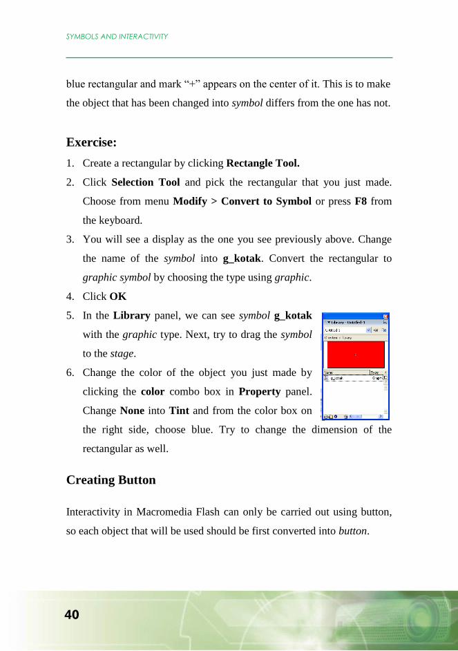
5. In the Library panel, we can see symbol g_kotak
with the graphic type. Next, try to drag the symbol
to the stage.
6. Change the color of the object you just made by
clicking the color combo box in Property panel.
Change None into Tint and from the color box on
the right side, choose blue. Try to change the dimension of the
rectangular as well.
Creating Button
Interactivity in Macromedia Flash can only be carried out using button,
so each object that will be used should be first converted into button.

41
To convert an object into a button, you have to highlight the object which
will be converted first, then choose menu Modify>convert to symbol
and click button. After this is done, the object has become a symbol
button and is facilitated by all properties related to button.
If we edit a symbol which is a button, the button
object that we click will be put into a specific space
particularly to manipulate the chosen button. Its
timeline will be like the one shown in the picture on the right side, in
which there are four frame options namely up, over, down, and hit.
Up : form of the button when the cursor of mouse is
not on it
Over : form of the button when the cursor of mouse is
on it
Down : form of the button when the mouse clicks it
Hit : to define the area width of the button
We can insert different forms and colors in each frame above.
Exercise:
Create a button shaped rectangular whose corner with radius 20
1. Create a rectangular by clicking rectangle tool
2. Before drawing on stage, first set the corner radius to 20. Click option
in tool box and choose set corner radius and fill in with 20 point.
3. Draw the rectangular in stage.
4. Activate the rectangular and
convert into the form of symbol

SYMBOLS AND INTERACTIVITY
42
and choose button. Then, name it b_tombol.
5. Edit the button by clicking twice
or you can do it from the menu
Edit > Edit in Place. You will see
the display as the one shown on
the right. You can notice the
timeline changed into the form of frame for button. (up, over, down,
hit)
6. Make the new key frame for frame Over, Down, and Hit by pressing
F6 in the frame.
7. Click on frame Over, and change the color of the rectangular. You
can use other color, such as blue.
8. Click on frame Down and move the rectangular using arrow buttons.
Move down twice and then move to the right twice.
9. Click on Scene 1 or choose from Edit > Edit Document or
CTRL+E from keyboard to finish symbol editing.
10. Start to use it by pressing CTRL+ENTER and move the cursor to
the button. Look and notice what will happen. The cursor will change
into hand form and the color of the button will change into blue. And
also try to click the button and see what will happen.
Giving Command to a Button
When you click a button and nothing happens, this is because the button
has not yet been assigned a command to perform certain task.
Macromedia Flash provides a facility to assign command to perform task
which is called action. The rules defined (programming language) by

43
Macromedia Flash to assign command is known by the name
ActionScript.
Actionscript can be applied either on button or frame. For example, to
stop a certain program from running in particular frame, you can give
command „stop‟ () in that frame.
Exercise:
1. Make new layer in timeline and name it “action”. Choose menu
Insert > Timeline > Layer.
Click twice on the name of the
new layer and rename it with
action.
2. In frame 1 of layer action,
choose Window > Layer or press F9, and window Action will be
opened.
3. Choose mark + and you will see the display as shown on the right.
Choose Global Functions >
Timeline Control > Stop.
4. In line 1, you can read stop();
and in frame 1 of layer action,
letter a signposts that there is
actionscript in the frame.
5. Press F9 to close window Action. Then, try to press CTRL+ENTER.
You will see that the movie in frame 1 will stop because of the stop
command.
Huruf a menunjukkan bahwa
di frame tersebut ada perintah
action

SYMBOLS AND INTERACTIVITY
44
To assign a command for a button has almost similar steps as the one for
a frame. The only difference is that in frame we have to click on it first
before we assign the command, and in button we have to click on the
button we will assign and choose the event to occur. For example, the
command will be carried out as the button is pressed.
If we want to assign command on a button that we just made by clicking,
we have to click the button first then we show the window action and
choose the event, next we write the command we want. For clearer
understanding, we will do the exercise of assigning command on the
button that we have made. The command will manage how the next
frame operates.
Exercise:
1. Put the button just made in frame 1 which has been assigned
command stop.
2. Add text ”play” on the button by clicking Text tool and direct it to
the button. Set the text to be fit inside the button.
3. Click the button and press F9 to open window action. Look into
Current selection to make sure that the button selected is the active
one.
4. Type command as shown below in the space provided.
on (release) { play();}
Be careful when writing the command. The color of the written text is
blue if the text is correct and well-written. ActionScript is case
sensitive meaning the uppercase is considered different from
lowercase. The command shown above means if the mouse is

45
released from the button (on release) the command play will operate.
Command play is used to replay the animation/movie that has been
paused by command stop.
5. Add keyframe from frame 2 until frame 10. Add bigger text stated
“Replay”.
6. Play the movie using CTRL+ENTER. The frame will stop at frame
1. Go on by clicking the button with command “play”, so flash will
continue the animation by going to the next frames containing
command “replay”, and it will stop again as it reaches back frame 1
(due to “stop” command).
Below are some basic commands often used in designing program using
Flash.
- Go To (gotoAndPlay, gotoAndStop): to jump to a particular frame or
scene.
- Play and stop : to play and stop the animation.
- Load Movie and Unload Movie: to view or delete animation.
- Tell Target : to control other animations and clips.
- If Frame is Loaded : to perform action which will monitor
whether particular frame is already played.
- Get URL : to link to a particular site.
- FSCommand : to control Flash player which plays the
animation.

SYMBOLS AND INTERACTIVITY
46


![MACROMEDIA FLASH 5. MIÉRT PONT FLASH? - vision.vein.huvision.vein.hu/~woodpaul/mm_vv/flashjegyzet[DETKI].pdf · MACROMEDIA FLASH 5. 1 BEVEZETÉS MIÉRT PONT FLASH? Mára a flash](https://img.dokumen.tips/doc/110x75/5d058cd088c993ea578bf881/macromedia-flash-5-miert-pont-flash-woodpaulmmvvflashjegyzetdetkipdf.jpg)