Embed Size (px)
Citation preview

VIRTUALIZE, SPLIT, AND REORGANIZE ✱
J U LY 2 2 , 2016 ✱ E R I C S S O N T E C H N O L O G Y R E V I E W 1
ERICSSON TECHNOLOGY
RF
RF
BPF
RCF
PPF
C H A R T I N G T H E F U T U R E O F I N N O V A T I O N V O L U M E 9 3 | # 6 ∙ 2 0 1 6
4G/5G RAN ARCHITECTURE: HOW A SPLIT CAN MAKE THE DIFFERENCE

✱ VIRTUALIZE, SPLIT, AND REORGANIZE
2 E R I C S S O N T E C H N O L O G Y R E V I E W ✱ J U LY 2 2 , 2016
ERIK WESTERBERG
As 5g evolves, many innovative services like extreme mobile broadband and long-range massive mtc will come into play. In line with the evolution of 4g and the introduction of 5g, ran architecture is undergoing a transformation: to increase deployment flexibility and network dynamicity, enabling networks to meet increasing performance requirements, while at the same time keeping a lid on the total cost of ownership. The proposed future-proof software-configurable split architecture will be able to support new services, deployed on general-purpose and specialized hardware, with functions ideally placed to maximize scalability, spectrum, and energy efficiency, all while supporting the concept of network slicing.
t h e r e q u i r e m e n t s created by extreme mbb, the IoT, and massive mtc call for an alternative to today’s deployment architectures. The changes to architecture include the capability to place selected functions closer to the network edge, for example, and the ability to increase ran resilience. Cost is naturally a factor, as
spectrum availability and site infrastructure continue to dominate operator expenditure for wide-area systems. The evolution of ran architecture therefore needs to include measures for enhanced spectrum efficiency that are harmonized with other improvements in the areas of hardware performance and energy efficiency.
4G/5G RANHOW A SPLIT CAN MAKE THE DIFFERENCEarchitecture

VIRTUALIZE, SPLIT, AND REORGANIZE ✱
J U LY 2 2 , 2016 ✱ E R I C S S O N T E C H N O L O G Y R E V I E W 3
In light of these cost and performance requirements, a number of capabilities are shaping the evolution path of ran architecture:
Seamless Radio Resource Management The best combination of any radio beam within reach of a user should be used for connectivity across all access network technologies, antenna points, and sites. This capability will be achieved by applying carrier aggregation, dual connectivity, comp, and a number of mimo and beamforming schemes.
Functional splitSome 5g requirements — such as ultra-low latency and ultra-high throughput — require highly flexibleran architecture and topology. This will be enabled by splitting ran functions, including the separation of the user plane (up) and the control plane (cp) in higher layers.
Dynamic and software-defined ranThe capability to configure, scale, and reconfigure logical nodes through software commands enables the ran to dynamically adjust to changing traffic conditions, hardware faults, as well as new service requirements. This capability will be achieved by separating out logical nodes suitable for virtualization (on a gpp) and designing functions that require specialized hardware to be dynamically (re)configurable on an spp.
Deployment flexibilityDeployment flexibility enables an operator to deploy and configure the ran with maximum spectrum efficiency and service performance regardless of the site topology, transport network characteristics, and spectrum scenario.
This is achieved through a correct split of the ran architecture into logical nodes, combined with the future-proof freedom to deploy each node type in the sites that are most appropriate given the physical topology and service requirements.
The process to reach the target architecture with the correct split involves a number of steps:〉〉 determining the logical functions that comprise 5g ran
on a level below 3gpp
〉〉 identifying the latency-critical functions that need to be placed within a few ttis to antenna elements
〉〉 identifying which functions have more relaxed latency requirements
Terms and abbreviations bpf — baseband processing function | co — central office | comp — coordinated multipoint | cp — control plane | cpri — Common Public Radio Interface | c-ran — cloud RAN | dl — downlink | epc — Evolved Packet Core | e2e — end-to-end | gpp — general purpose processor | harq — hybrid automatic repeat request | iot — Internet of Things | mac — media access controller | mbb — mobile broadband | mimo — multiple-input, multiple-output | mtc — machine-type communications | nfv — Network Functions Virtualization | nr — next generation rat | oss — operations support systems | pdcp — packet data convergence protocol | pdu — protocol data unit | pgw — packet data network gateway | phy — physical interface transceiver | ppf — packet processing function | rat — radio-access technology | rcf — radio control function | rdc — regional data center | rf — radio function | rlc — Radio Link Control | rrm — Radio Resource Management | son — self-organizing networks | spp — special purpose processor | s-rrm — server rrm | tti — time transmit interval | ue — user equipment | ul — uplink | up — user plane | u-rrm — user rrm | vnf — Virtualized Network Function
THE CAPABILITY TO CONFIGURE, SCALE, AND RECONFIGURE LOGICAL NODES THROUGH SOFTWARE COMMANDS ENABLES THE RAN TO DYNAMICALLY ADJUST TO CHANGING TRAFFIC

✱ VIRTUALIZE, SPLIT, AND REORGANIZE
4 E R I C S S O N T E C H N O L O G Y R E V I E W ✱ J U LY 2 2 , 2016
RAN domain
Devicefunctions
OSS
MME
SGW
Radio andantennas
PHYcontrol
PHYcontrol
PHYcontrol
L1/PHY
MAC RLC
SysAreahandling
UEhandling
Framehandling
Multipathhandling PDCP S1-U
S1-MME
Radio andantennas
Mgmt andanalytics
Mgmt andanalytics
Mgmt andanalytics
Mgmtand SON
Figure 1: The logical 4g/5g
ran architecture — one level below 3gpp
〉〉 determining where to place anchor points for soft combining, carrier aggregation, and dual connectivity — among the user-plane functions
〉〉 identifying which nodes can be implemented as vnfs
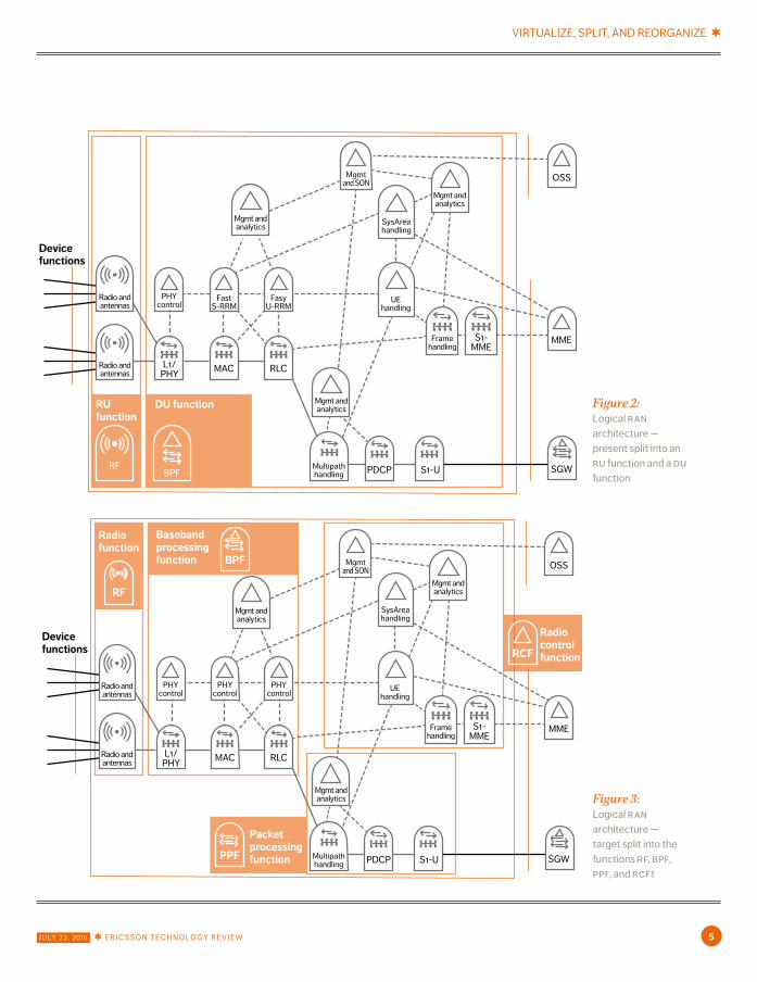
This process is illustrated in Figures 1, 2, and 3. Figure 1 shows the 4g/5g logical architecture at a level below 3gpp; Figure 2 shows today’s 4g split into an ru and a du; and Figure 3 shows the target split architecture. Throughout the process, and as a result of the functional decomposition, new inter-node interfaces emerge, whose characteristics need to be taken into consideration to ensure that the underlying transport network can support the various deployment scenarios.
The logical 4g/5g ran architectureThe external interfaces of the ran domain (except to the oss) are standardized under 3gpp, as is the functional behavior of the ran domain as a whole. Below the high-level specification, 3gpp leaves
room for innovation to enhance the network with ran-internal value-add features — a flexibility that has over a number of years resulted in continuous improvement in many areas, including spectrum efficiency (in the form of scheduling algorithms, power control algorithms, and various rrm features), energy efficiency, and enhancements to service characteristics such as lower latencies. To determine the optimal architectural split, however, the ran architecture needs to be examined with a finer level of granularity than that offered by 3gpp.
ran anchor points Figure 1 illustrates the logical ran architecture, which for the purposes of simplification shows the ul and dl instances of each function combined, and the solid lines indicate user plane functions. In the downlink, pdus enter the ran domain over the s1-u interface (right) and are delivered to devices (on the left) over the radio interface. The multipath-handling function is the anchor point for
VIRTUALIZE, SPLIT, AND REORGANIZE ✱
J U LY 2 2 , 2016 ✱ E R I C S S O N T E C H N O L O G Y R E V I E W 5
Basebandprocessingfunction
Radiofunction
Radiocontrolfunction
RF
RCF
Devicefunctions
OSS
MME
SGW
Radio andantennas
PHYcontrol
PHYcontrol
PHYcontrol
L1/PHY
MAC RLC
SysAreahandling
UEhandling
Framehandling
Multipathhandling PDCP S1-U
S1-MME
Mgmt andanalytics
Mgmt andanalytics
Mgmt andanalytics
Mgmtand SON
Radio andantennas
PacketprocessingfunctionPPF
BPF
FastS-RRM
FasyU-RRM
Devicefunctions
OSS
MME
SGW
Radio andantennas
PHYcontrol
L1/PHY
MAC RLC
SysAreahandling
UEhandling
Framehandling
Multipathhandling PDCP S1-U
S1-MME
Mgmt andanalytics
Mgmt andanalytics
Mgmt andanalytics
Mgmtand SON
Radio andantennas
DU functionRUfunction
RFBPF
Figure 2: Logical ran architecture — present split into an ru function and a du function
Figure 3: Logical ran architecture — target split into the functions rf, bpf, ppf, and rcft
✱ VIRTUALIZE, SPLIT, AND REORGANIZE
6 E R I C S S O N T E C H N O L O G Y R E V I E W ✱ J U LY 2 2 , 2016
dual connectivity, which schedules individual pdcp pdus in the same user-data stream to different rlc instances, possibly on different rats. In this way, a single ue can simultaneously receive and send data over different radio channels — for example, one nr and one lte channel — that are connected to different sites. The mac function is the anchor point for carrier aggregation, which schedules mac pdus to each user over a multitude of 4g or 5g carriers. The mac function handles comp and multi-beam transmissions. In the uplink, the l1/phy function performs soft combining, the mac function aggregates ul data in carrier aggregation, and multipath handling aggregates data received from dual connectivity ul data streams.
The harq loop 3gpp specifies retransmission periods and response times at the radio level between the ue and the network as the harq loop, which includes: the air-interface transmission time, completion times for rf-l1/phy-mac functions, and rf-l1/phy-mac functions in the ue.
The loop results in a standardized round-trip latency budget of 3ms for lte, and down to 200µs for nr. The ran functions participating in the loop work synchronously with the air-interface tti, while the pdcp and multipath handling function feed and receive packets traveling to and from the rlc layer asynchronously — which has implications for the split architecture.
Control plane functions Runtime control functions can generally be divided into three categories, depending on whether they: act on a per-user basis (u-rrm), control spectrum on a system level (s-rrm), or manage infrastructure and other common resources.
The u-rrm functions include measurement reporting, selection of modulation and coding schemes, per-ue bearer handling, and handover execution. The functions in fast u-rrm act within the harq loop and serve the scheduler with processed real-time per-ue information. In contrast, the u-rrm function (ue-handling) works on a time scale of 10ms and above, including bearer handling,
per-ue policy handling, handoff control, and more. Functions that control spectrum on the system
level include radio scheduling, distribution of the power budget across active ues, and system-initiated load-sharing handovers. The fast s-rrm operating within the harq loop is responsible for radio scheduling and functions in tight coordination with the mac and rlc. System-area handlers — such as load sharing, system information control, and dual-connectivity control — control spectrum on a 10ms time scale, or slower.
Functions that control infrastructure and common resources — other than spectrum — include handling of transport, connectivity, hardware, and energy. By allowing the control functions for spectrum, transport, infrastructure, and connectivity to interact, a holistic control system for ran resources can be built.
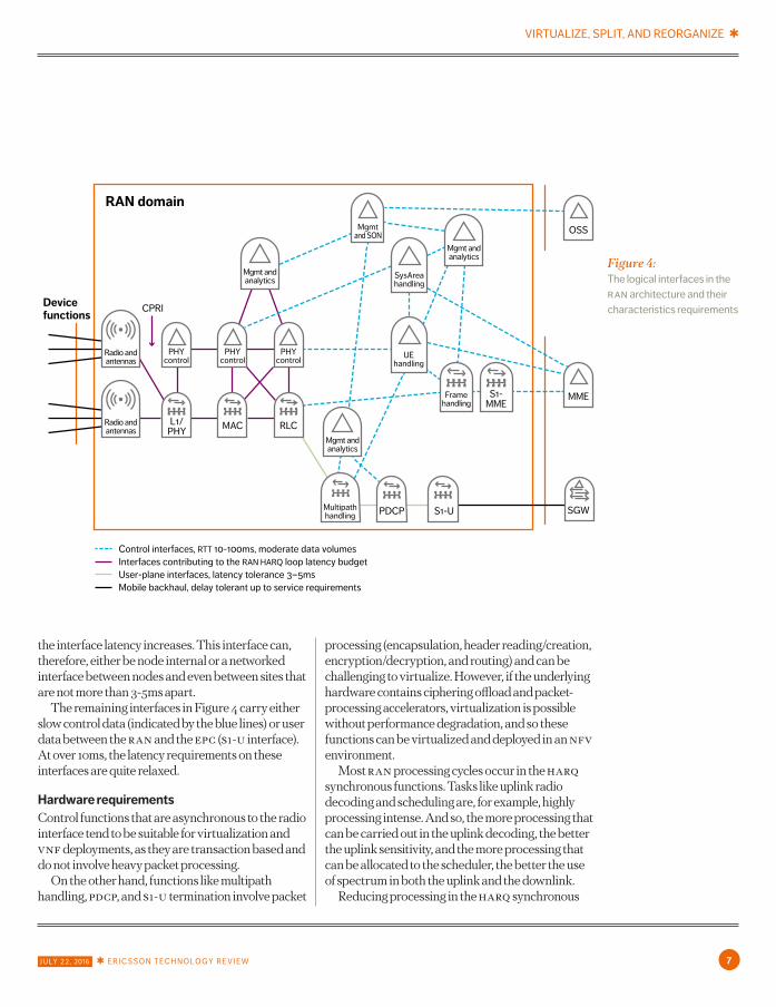
Interface characteristics The ran harq loop time budget of three ttis is divided into time for processing, and time for signals and data to traverse the various inter-function interfaces. The less time spent on interface signaling, the more time is available for processing, which translates into lower cost for hardware and for energy consumption. To minimize signaling latency, and thus maximize hardware efficiency, the mac, rlc, and fast-u/s-rrm functions should run on the same hardware instance. As traffic moves to the right in Figure 4, the requirement on interface latency gradually relaxes.
The cpri scales with effective carrier bandwidth and the number of antenna elements. An inter-site cpri interface with joint combining at the central office (co) can, in many deployments, result in a gain in uplink spectrum. For lte, the cpri can be inter-site (a few gbps), but in nr — with wider carriers and more antenna elements — an inter-site cpri would be challenging from both a latency and bandwidth perspective.
The interface between the rlc and the multipath handler scales with user data and has a latency tolerance in the order of several milliseconds. This interface is limited by the performance of the dual connectivity feature, which degrades gracefully as
VIRTUALIZE, SPLIT, AND REORGANIZE ✱
J U LY 2 2 , 2016 ✱ E R I C S S O N T E C H N O L O G Y R E V I E W 7
RAN domain
Devicefunctions
CPRI
Control interfaces, RTT 10-100ms, moderate data volumesInterfaces contributing to the RAN HARQ loop latency budgetUser-plane interfaces, latency tolerance 3–5msMobile backhaul, delay tolerant up to service requirements
OSS
MME
SGW
Radio andantennas
PHYcontrol
PHYcontrol
PHYcontrol
L1/PHY
MAC RLC
SysAreahandling
UEhandling
Framehandling
Multipathhandling PDCP S1-U
S1-MME
Mgmt andanalytics
Mgmt andanalytics
Mgmt andanalytics
Mgmtand SON
Radio andantennas
Figure 4: The logical interfaces in the ran architecture and their characteristics requirements
the interface latency increases. This interface can, therefore, either be node internal or a networked interface between nodes and even between sites that are not more than 3-5ms apart.
The remaining interfaces in Figure 4 carry either slow control data (indicated by the blue lines) or user data between the ran and the epc (s1-u interface). At over 10ms, the latency requirements on these interfaces are quite relaxed.
Hardware requirements Control functions that are asynchronous to the radio interface tend to be suitable for virtualization and vnf deployments, as they are transaction based and do not involve heavy packet processing.
On the other hand, functions like multipath handling, pdcp, and s1-u termination involve packet
processing (encapsulation, header reading/creation, encryption/decryption, and routing) and can be challenging to virtualize. However, if the underlying hardware contains ciphering offload and packet-processing accelerators, virtualization is possible without performance degradation, and so these functions can be virtualized and deployed in an nfv environment.
Most ran processing cycles occur in the harq synchronous functions. Tasks like uplink radio decoding and scheduling are, for example, highly processing intense. And so, the more processing that can be carried out in the uplink decoding, the better the uplink sensitivity, and the more processing that can be allocated to the scheduler, the better the use of spectrum in both the uplink and the downlink.
Reducing processing in the harq synchronous

✱ VIRTUALIZE, SPLIT, AND REORGANIZE
8 E R I C S S O N T E C H N O L O G Y R E V I E W ✱ J U LY 2 2 , 2016
RUHW SPP GPP
Devicefunctions
Radio andantennas
PHYcontrol
FastS-RRM
FastU-RRM
L1/PHY
MAC RLC
OSS
MME
SGW
SysAreahandling
UEhandling
Framehandling
Multipathhandling PDCP S1-U
S1-MME
Mgmt andanalytics
Mgmt andanalytics
Mgmtand SON
Radio andantennas
Mgmt andanalytics
Figure 5: Preferred execution
environments for the various ran
functions
Figure 6: Hierarchy,
instantiation, and inter-node interfaces
in the ran split architecture
Sys area 4Sys area 3Sys area 2
OSS
RCF
MME
RF RF RF RF RF RF
Sys area 1
S1-MME
S1-U CC-IBB-CI
BB-II
BB-UI
C1
RF RF RF RF
BPF1 BPF2 BPF3 BPF4
PPF1 PPF2
SGW

VIRTUALIZE, SPLIT, AND REORGANIZE ✱
J U LY 2 2 , 2016 ✱ E R I C S S O N T E C H N O L O G Y R E V I E W 9
functions is not a good idea if spectrum efficiency is to be maintained or improved. Special-purpose multi-core hardware is best suited to this type of processing, as its price-performance ratio is presently five times that of single-core hardware. And so, harq synchronous functions are likely to continue to run on special purpose processor (spp) hardware for at least one or two more generations of ran hardware.
To avoid flow control issues between the mac and the rlc — and given the level of interaction between the scheduler and rlc — the mac, rlc, and the fast rrm should run on the same hardware instance. The resulting hardware environment is shown in Figure 5.
The functions on the right in the illustration (blue area) run on general purpose processors (gpps) that include hardware accelerators and ciphering offload for multipath handling and pdcp. The functions in the middle (green area) run on spps with multi-core hardware suitable for supporting functions in the harq loop, and the radio hardware is on the left (yellow area).
Resulting split architecture Based on function and interface characteristics, preferred execution environment, and spectrum efficiency, the target functional composition, which is shown in Figure 6, includes the following logical ran nodes:
Packet processing function — ppf The ppf, which is suitable for virtualization, contains user-plane functions that are asynchronous to the harq loop, and includes the pdcp layer — such as encryption — and the multipath handling function for the dual connectivity anchor point and data scheduling.
Baseband processing function — bpfGiven the stringent requirements for spectrum efficiency, the bpf benefits from being placed on an spp. The bpf includes user-plane functions that are synchronous to the harq loop, including the rlc, mac, and l1/phy, and it is also the anchor point for carrier aggregation (mac) and soft combining (l1/
phy). The bpf contains the per-tti rrm (fast radio scheduler), and is also responsible for the comp, for the selection of the mimo scheme, and for beam and antenna elements.
Radio function — rf The rf requires special radio hardware and includes functions such as modulation, d/a conversion, filtering, and signal amplification.
Radio control function — rcf The rcf handles load sharing among system areas and different radio technologies, as well as the use of policies to control the schedulers in the bpfs and ppfs. At the user and bearer level, the rcf negotiates qos and other policies with other domains, and is responsible for the associated sla enforcement in the ran. The rcf controls the overall ran performance relative to the service requirement, creates and manages analytics data, and is responsible for the ran son functions. Like the ppf, the rcf is suitable for virtualization.
The logical interfaces are:〉〉 c1 — an evolution of the cpri interface, this interface
scales with effective carrier bandwidth (carrier bandwidth × number of antenna streams) with a latency requirement of around one tti (1ms for lte and down to 67µs for nr).
〉〉 bb-ui — the user-plane interface between the ppf and the bpf, it carries pdcp pdus, which scale according to the amount of user data sent by the bpf instance to the system area.
〉〉 bb-ii — the interface between two bpf instances, it carries user data for scenarios that use inter-bpf carrier aggregation (carrier aggregation over two carriers controlled by two different bpf instances). This interface also carries control data for the inter-bpf comp, scales in line with the amount of user data transmitted, and the latency requirement is the same as for c1.
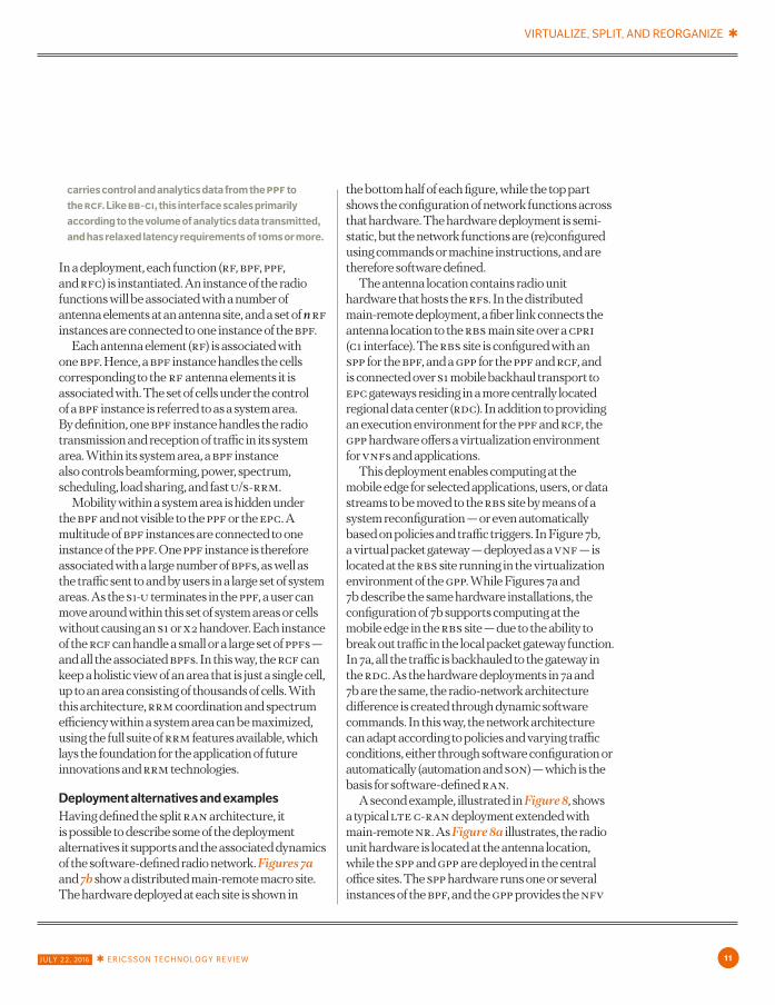
〉〉 bb-ci — the control-plane interface for the bpfs, which carries control and analytics data from the bpf to the rcf. This interface primarily scales with the volume of analytics data, and at 10ms or more, the latency requirements are quite relaxed.
〉〉 cc-i — the control-plane interface for the ppfs, which
✱ VIRTUALIZE, SPLIT, AND REORGANIZE
10 E R I C S S O N T E C H N O L O G Y R E V I E W ✱ J U LY 2 2 , 2016
RCF
RUHW SPP GPP GPP
Antennalocation RBS site
Functions/softwareconfiguration
Hardwaredeploymentacross sitetypes
1 st level CO 2nd level CO RDC
RF
RFBPF PPF
MME
SGW PGW
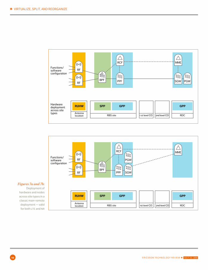
Figures 7a and 7b: Deployment of
hardware and nodes across site types in a classic main-remote deployment — valid for both lte and nr
RCF
RUHW SPP GPP GPP
Antennalocation RBS site
Functions/softwareconfiguration
1st level CO 2nd level CO RDC
RF
RFBPF
PPF
MME
SGW
PGW
VIRTUALIZE, SPLIT, AND REORGANIZE ✱
J U LY 2 2 , 2016 ✱ E R I C S S O N T E C H N O L O G Y R E V I E W 11
carries control and analytics data from the ppf to the rcf. Like bb-ci, this interface scales primarily according to the volume of analytics data transmitted, and has relaxed latency requirements of 10ms or more.
In a deployment, each function (rf, bpf, ppf, and rfc) is instantiated. An instance of the radio functions will be associated with a number of antenna elements at an antenna site, and a set of n rf instances are connected to one instance of the bpf.
Each antenna element (rf) is associated with one bpf. Hence, a bpf instance handles the cells corresponding to the rf antenna elements it is associated with. The set of cells under the control of a bpf instance is referred to as a system area. By definition, one bpf instance handles the radio transmission and reception of traffic in its system area. Within its system area, a bpf instance also controls beamforming, power, spectrum, scheduling, load sharing, and fast u/s-rrm.
Mobility within a system area is hidden under the bpf and not visible to the ppf or the epc. A multitude of bpf instances are connected to one instance of the ppf. One ppf instance is therefore associated with a large number of bpfs, as well as the traffic sent to and by users in a large set of system areas. As the s1-u terminates in the ppf, a user can move around within this set of system areas or cells without causing an s1 or x2 handover. Each instance of the rcf can handle a small or a large set of ppfs — and all the associated bpfs. In this way, the rcf can keep a holistic view of an area that is just a single cell, up to an area consisting of thousands of cells. With this architecture, rrm coordination and spectrum efficiency within a system area can be maximized, using the full suite of rrm features available, which lays the foundation for the application of future innovations and rrm technologies.
Deployment alternatives and examples Having defined the split ran architecture, it is possible to describe some of the deployment alternatives it supports and the associated dynamics of the software-defined radio network. Figures 7a and 7b show a distributed main-remote macro site. The hardware deployed at each site is shown in
the bottom half of each figure, while the top part shows the configuration of network functions across that hardware. The hardware deployment is semi-static, but the network functions are (re)configured using commands or machine instructions, and are therefore software defined.
The antenna location contains radio unit hardware that hosts the rfs. In the distributed main-remote deployment, a fiber link connects the antenna location to the rbs main site over a cpri (c1 interface). The rbs site is configured with an spp for the bpf, and a gpp for the ppf and rcf, and is connected over s1 mobile backhaul transport to epc gateways residing in a more centrally located regional data center (rdc). In addition to providing an execution environment for the ppf and rcf, the gpp hardware offers a virtualization environment for vnfs and applications.
This deployment enables computing at the mobile edge for selected applications, users, or data streams to be moved to the rbs site by means of a system reconfiguration — or even automatically based on policies and traffic triggers. In Figure 7b, a virtual packet gateway — deployed as a vnf — is located at the rbs site running in the virtualization environment of the gpp. While Figures 7a and 7b describe the same hardware installations, the configuration of 7b supports computing at the mobile edge in the rbs site — due to the ability to break out traffic in the local packet gateway function. In 7a, all the traffic is backhauled to the gateway in the rdc. As the hardware deployments in 7a and 7b are the same, the radio-network architecture difference is created through dynamic software commands. In this way, the network architecture can adapt according to policies and varying traffic conditions, either through software configuration or automatically (automation and son) — which is the basis for software-defined ran.
A second example, illustrated in Figure 8, shows a typical lte c-ran deployment extended with main-remote nr. As Figure 8a illustrates, the radio unit hardware is located at the antenna location, while the spp and gpp are deployed in the central office sites. The spp hardware runs one or several instances of the bpf, and the gpp provides the nfv

✱ VIRTUALIZE, SPLIT, AND REORGANIZE
12 E R I C S S O N T E C H N O L O G Y R E V I E W ✱ J U LY 2 2 , 2016
Figure 8a and 8b: c-ran deployment
with (instance a) a centralized
packet gateway and (instance b) a
second instance of the pgw distributed
to the co site for local breakout of
selected traffic
NR RUHW
LTE RUHWSPP SPP GPP GPP
Antenna location RBS site 1st level CO 2nd level CO RDC
NRRF
NRRF
LTERF
LTERF
NRBPF
LTEBPF
PPF
RCF
MME
SGW PGW
Functions/softwareconfiguration
Hardwaredeploymentacross sitetypes
NR RUHW
LTE RUHWSPP SPP GPP GPP
Antenna location RBS site
Functions/softwareconfiguration
1st level CO 2nd level CO RDC
NRRF
NRRF
LTERF
LTERF
NRBPF
LTEBPF
PPF
RCF
MME
SGW PGW1
PGW2
Hardwaredeploymentacross sitetypes

VIRTUALIZE, SPLIT, AND REORGANIZE ✱
J U LY 2 2 , 2016 ✱ E R I C S S O N T E C H N O L O G Y R E V I E W 13
environment for the ppf and the rcf. Compared with the distributed macro deployment shown in Figure 7a, the lte bpf in the c-ran deployment holds a more centralized position. Each instance of the bpf covers more antenna locations, which results in high spectrum efficiency, as the bpf can use the complete set of fast rrm features — including joint combining, multipoint transmission, and coordinated scheduling — across all the antenna points in the system area covered by the first-level central office site.
The c-ran deployment requires high-bandwidth fiber for the c1 interface between the bpf and the rf (cpri fronthaul). Like the distributed macro architecture of 7b, the c-ran deployment offers a gpp environment for vnfs and applications in the central office. The gpp may be part of a distributed data center, in which case, the ppf and rcf are deployed as vnfs, while the spp is deployed as standalone hardware. Alternatively, the spp can be part of the distributed data center, providing specialized hardware for the bpf — similar to the way other types of data-center specialized hardware can be used by applications with special needs,
such as packet processing or firewalling. In this way, next generation central offices can be turned into a combination of mobile-edge sites and baseband hotels.
The flexible c-ran architecture illustrated in Figure 9 supports more centralized deployments compared with the c-ran configuration shown in Figure 8. The gpp in the flexible c-ran architecture is provisioned at the next level in the hierarchy, moving the ppf and hence the dual-connectivity anchor point to a more central position, which enables smooth dual connectivity mobility. Spectrum efficiency is the same or slightly improved, the number of distributed data centers drops, and the mobile edge is slightly more centralized. The transport requirements of both c-ran configurations are similar.
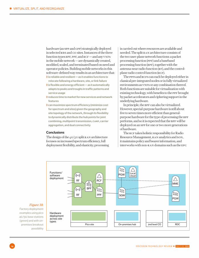
Figure 10 shows an on-premises architecture that is fully self-contained using pico base stations and an on-premises data center hub that stores content and carries out processing locally. In this case, all four ran nodes (rf, bpf, ppf, and rcf) are integrated onto the same chip.
The ideal split architecture contains pools of
NR RUHW
LTE RUHWSPP SPP GPP GPP
Antenna location RBS site
Functions/softwareconfiguration
1st level CO 2nd level CO RDC
NRRF
NRRF
LTERF
LTERF
NRBPF
LTEBPF
PPF
RCF
MME
SGW PGW1
PGW2
Hardwaredeploymentacross sitetypes
Figure 9: Flexible c-ran architecture second-level co for better dual connectivity performance
✱ VIRTUALIZE, SPLIT, AND REORGANIZE
14 E R I C S S O N T E C H N O L O G Y R E V I E W ✱ J U LY 2 2 , 2016
hardware (an spp and gpp) strategically deployed in selected rbs and co sites. Instances of the three function types bpf, ppf, and rcf — and any vnfs in the mobile network — are dynamically created, modified, scaled, and terminated based on need and operator policies. Building mobile networks in this software-defined way results in an architecture that:〉〉 is reliable and resilient — as it enables functions to
relocate following a hardware, site, or link failure〉〉 is flexible and energy efficient — as it automatically
adapts to peaks and troughs in traffic patterns and service usage
〉〉 reduces time to market for new services and network features
〉〉 can maximize spectrum efficiency (minimize cost for spectrum and sites) given the geography and site topology of the network, through its flexibility to dynamically distribute the hub points for joint combining, multipoint transmission, comp, carrier aggregation, and dual connectivity
Conclusions The design of the 4g/5g split ran architecture focuses on increased spectrum efficiency, full deployment flexibility, and elasticity; processing
is carried out where resources are available and needed. The split ran architecture consists of the two user-plane network functions: a packet processing function (ppf) and a baseband processing function (bpf), together with the antenna-near radio function (rf), and the control-plane radio control function (rcf).
The ppfs and rcfs can each be deployed either in classical pre-integrated nodes or in fully virtualized environments as vnfs or any combination thereof. Both functions are suitable for virtualization with existing technology, with benefits to the ppf brought by packet accelerators and ciphering support in the underlying hardware.
In principle, the bpf can also be virtualized. However, special-purpose hardware is still about five to seven times more efficient than general-purpose hardware for the type of processing the bpf performs, and so it is expected that the bpf will be deployed on an spp for one or two more generations of hardware.
The rcf takes holistic responsibility for Radio Resource Management, ran analytics and son, it maintains policy and bearer information, and interworks with non-ran domains such as the epc
Pico site
Functions/softwaredeployment
On-premises hub 2nd level CO RDC
RF
RF
BPF
SGW
PGW Localcloud
RCFMME
PPFPGW
Hardwaredeploymentacross sitetypes
Figure 10: Factory deployment examples using pico 4g/5g base stations (green) and with on-
premises breakout possibility

VIRTUALIZE, SPLIT, AND REORGANIZE ✱
J U LY 2 2 , 2016 ✱ E R I C S S O N T E C H N O L O G Y R E V I E W 15
Erik Westerberg ◆ joined Ericsson from mit, Massachusetts, the us, in 1996 and is a senior expert in system and network architecture. During his first 10 years at Ericsson, he worked with development of the mobile broadband systems before broadening his field to include the full network architecture. He presently holds the position of chief network architect in Ericsson's Business Unit Network Products. He holds a Ph.D. in quantum physics from Stockholm University, Sweden.
au
th
or and resource orchestration layers. The rcf can be
centralized or distributed in a closed on-premises factory network, for example. Deploying the user-plane bpf (processing synchronous to the tti) and ppf (asynchronous packet processing) can be achieved in a variety of ways, as long as the bpf is within one to two ttis from the antenna points. The ppf, on the other hand, can be more centralized, with a distance of up to 5-7ms from the radio functions. And so user-plane functions can be deployed to match service requirements, and maximize spectrum efficiency according to the spectrum, transport, and site availability, as well as the particular local geography.
The split architecture results in the necessary scaling dimensions to support 5g use cases and traffic structures in a cost-efficient way. Its flexibility and decoupling of hardware from software enables a software-defined elastic resilient ran. It also guarantees that ran architecture is future-proof. As an evolution of 4g ran, the split can be gradually introduced in line with business needs.

✱ VIRTUALIZE, SPLIT, AND REORGANIZE
16 E R I C S S O N T E C H N O L O G Y R E V I E W ✱ J U LY 2 2 , 2016
ISSN 0014-0171284 23-3283 | Uen
© Ericsson AB 2016EricssonSE-164 83 Stockholm, SwedenPhone: +46 10 719 0000